EP1416554A1 - SEALING MATERIAL COATING METHOD FOR FUEL CELL−USE SEPARATOR - Google Patents
SEALING MATERIAL COATING METHOD FOR FUEL CELL−USE SEPARATOR Download PDFInfo
- Publication number
- EP1416554A1 EP1416554A1 EP02743780A EP02743780A EP1416554A1 EP 1416554 A1 EP1416554 A1 EP 1416554A1 EP 02743780 A EP02743780 A EP 02743780A EP 02743780 A EP02743780 A EP 02743780A EP 1416554 A1 EP1416554 A1 EP 1416554A1
- Authority
- EP
- European Patent Office
- Prior art keywords
- sealant
- coating
- separator
- fuel cell
- coated
- Prior art date
- Legal status (The legal status is an assumption and is not a legal conclusion. Google has not performed a legal analysis and makes no representation as to the accuracy of the status listed.)
- Granted
Links
Images











Classifications
-
- H—ELECTRICITY
- H01—ELECTRIC ELEMENTS
- H01M—PROCESSES OR MEANS, e.g. BATTERIES, FOR THE DIRECT CONVERSION OF CHEMICAL ENERGY INTO ELECTRICAL ENERGY
- H01M8/00—Fuel cells; Manufacture thereof
- H01M8/02—Details
- H01M8/0271—Sealing or supporting means around electrodes, matrices or membranes
- H01M8/0286—Processes for forming seals
-
- H—ELECTRICITY
- H01—ELECTRIC ELEMENTS
- H01M—PROCESSES OR MEANS, e.g. BATTERIES, FOR THE DIRECT CONVERSION OF CHEMICAL ENERGY INTO ELECTRICAL ENERGY
- H01M8/00—Fuel cells; Manufacture thereof
- H01M8/02—Details
-
- H—ELECTRICITY
- H01—ELECTRIC ELEMENTS
- H01M—PROCESSES OR MEANS, e.g. BATTERIES, FOR THE DIRECT CONVERSION OF CHEMICAL ENERGY INTO ELECTRICAL ENERGY
- H01M8/00—Fuel cells; Manufacture thereof
- H01M8/02—Details
- H01M8/0271—Sealing or supporting means around electrodes, matrices or membranes
-
- Y—GENERAL TAGGING OF NEW TECHNOLOGICAL DEVELOPMENTS; GENERAL TAGGING OF CROSS-SECTIONAL TECHNOLOGIES SPANNING OVER SEVERAL SECTIONS OF THE IPC; TECHNICAL SUBJECTS COVERED BY FORMER USPC CROSS-REFERENCE ART COLLECTIONS [XRACs] AND DIGESTS
- Y02—TECHNOLOGIES OR APPLICATIONS FOR MITIGATION OR ADAPTATION AGAINST CLIMATE CHANGE
- Y02E—REDUCTION OF GREENHOUSE GAS [GHG] EMISSIONS, RELATED TO ENERGY GENERATION, TRANSMISSION OR DISTRIBUTION
- Y02E60/00—Enabling technologies; Technologies with a potential or indirect contribution to GHG emissions mitigation
- Y02E60/30—Hydrogen technology
- Y02E60/50—Fuel cells
Definitions
- the present invention relates to a method for coating a sealant material on a fuel cell separator in which a sealant material is coated in uniform thickness to improve sealant coating quality and hence sealability for thereby improving the performance of a fuel cell.
- a fuel cell is arranged to produce electricity through a process for obtaining water by causing hydrogen and oxygen to react utilizing a principle opposite the water electrolysis.
- fuel gas is replaced by hydrogen
- air or an oxidant gas is replaced by oxygen.
- Such fuel cell is known from, for example, Japanese Patent Laid-Open Publication No. 2000-123848 entitled "Fuel Cell”.
- the known fuel cell has a cell as shown in exploded perspective in Fig. 24 hereof.
- an anode side electrode 202 and a cathode side electrode 203 are mated with an electrolytic film 201.
- a unit fuel cell (cell module) 200 is provided by sandwiching the afore- mentioned by a first separator 206 and a second separator 207 via gaskets 204, 205.
- the first separator 206 has on a surface 206a thereof a first flow path 208 for allowing passage of a fuel gas while the second separator 207 has on a surface 207a thereof a second flow path 209 for allowing passage of an oxidant gas, so that the fuel gas and the oxidant gas are guided to the electrolytic film 201.
- the first and second separators 206, 207 are provided to prevent the fuel gas and the oxidant gas from leaking to adjacent cells. They are called “separators" in this sense.
- the first separator 206 has on its surface 206a the flow path 208 for fuel gas, while the second separator 207 has on its surface 207a the flow path 209 for oxidant gas.
- first and second separators 206, 207 respectively have a fuel gas supplying hole portion 210a and an oxidant gas supplying hole portion 211a at one end portions thereof, and respectively have a fuel gas discharging hole portion 210b and an oxidant gas discharging hole portion 211b at the other end portions thereof.
- first and second separators 206, 207 have a cooling water supplying hole portion 212a for making cooling water pass through at one end portions thereof, and have a cooling water discharging hole portion 212b at the other end portions thereof.
- the present inventors have variously tried to manufacture a cell module by sandwiching a membrane electrode assembly formed from electrolytic films and electrodes by two separators, by coating a liquid sealant in place of the gaskets 204, 205 on the separator.
- a liquid sealant in place of the gaskets 204, 205 on the separator.
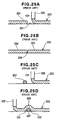
- Figs. 25A through 25D are operational views illustrating a method for coating a sealant on the separator for fuel cell. More concretely, Fig. 25A is an operational view showing a state before a coating-start and a coating-end of the sealant are connected; Fig. 25B is an operational view showing a state in which the coating-start and the coating-end of the sealant are connected; Fig. 25C is an operational view showing a state before the coating-start and the coating-end of the sealant are overlapped; and Fig. 25D is an operational view showing a state in which coating-start and coating-end of the sealant are overlapped.
- a space 226 comes into being between the coating-start portion 224 and the coating-end portion 225.
- Fig. 26 is an operational view illustrating the sealant coating procedure.
- the sealant 223 is coated on a separator 221 by a sealant coating gun 222, if the driving portion of the sealant coating gun 222 is stopped in order to end the coating at the coating-end portion 225 of the sealant 223, there are cases in which the sealant 223 which remains in a nozzle portion 234 of the sealant coating gun 222 drops down. This leads to deterioration of the sealant coating quality or deterioration of the sealability due to non-uniformity of the sealant thickness.
- Figs. 27A and 27B are operational views illustrating the procedure of coating the sealant onto a warped separator. More concretely, Fig. 27A is an operational view showing a state in the midst of coating the sealant, and Fig. 27B is an operational view showing a state after coating the sealant.
- Fig. 27A shows a state in which the sealant 223 is coated by the sealant coating gun 222 on the separator 221 placed on a placement platform 236.
- a sealant thickness th2 at the central portion of the separator 221 is smaller than a sealant thickness th 1 at the edge of the separator 221. Therefore, there is the concern that gas and water will leak from the portion at which the sealant 223 is thin.
- An object of the present invention is to coat a sealant to a uniform thickness on a separator for a fuel cell and to improve the sealant coating quality, and further, to improve the sealability and improve the performance of the fuel cell.
- the present invention provide a method for coating a sealant on a separator for a fuel cell which coats a liquid sealant at a periphery of a gas flow path and a water flow path of a separator by using means for coating a sealant which is formed from a motor, means for extruding a sealant driven by the motor, and a nozzle portion provided at a distal end of the means for extruding a sealant, wherein a sealing groove in which the sealant is coated is provided, and widths of the sealing groove at coating-start portion and coating-end portion of the sealant are made to be greater than widths of portions other than the coating-start portion and the coating-end portion, and the coating-start portion and the coating-end portion of the sealant are made to intersect at a place where the width of the sealing groove is made large.
- the coating-start portion and the coating-end portion of the sealant intersect, adhesion between the coating-start portion and the coating-end portion can be improved, and as compared with a case in which the distal end of the coating-start portion and the distal end of the coating-end portion are simply connected, it is possible to eliminate space between the coating-start portion and the coating-end portion, and the sealability can be improved.
- the coating-start portion and the coating-end portion are made to intersect at a place where the width of a sealing groove is made large, the degrees of freedom of the coated position of the sealant can be increased, and the coated position of the sealant can be set such that space between the coating-start portion and the coating-end portion can be eliminated, and an improvement in the sealability can be further aimed for.
- the horizontal moving velocity of the nozzle portion is made to be a low velocity and the sealant coated amount is reduced.
- the sealant can more easily adhere to the separator by taking time at the coating-end portion of the sealant, and when the coating-end portion is connected to the coating-start portion of the sealant, space between the coating-end portion and the coating-start portion can be eliminated, and the sealability can be improved.
- the means for coating a sealant is raising-lowering controlled so as to go along the outer periphery of the sealant at a point in time when the distal end of the means for coating a sealant has approached the coating-start portion of the sealant.
- the sealant coating gun is raising-lowering controlled so as to go along the outer periphery of the sealant at a point in time when the distal end of the means for coating a sealant has approached the coating-start portion of the sealant, the sealant can be coated so as to adhere to the outer periphery of the sealant of the coating-start portion, and space at the intersection portion between the coating-start portion and the coating-end portion of the sealant is eliminated, and it is possible to prevent gas and water from leaking from the intersection portion.
- a non-contact type sensor is additionally provided at the means for coating a sealant, and it is good to start raising-lowering control by detecting the coating-start portion of the sealant by the non-contact type sensor.
- the coating-start portion of the sealant can be precisely detected, and adhesion of the sealant which is coated on the coating-start portion can be improved, and the sealability can be further improved.
- the means for straightening straightens the warping of the separator and the sealant is coated on the separator while making the means for straightening work, the distance between the separator and the means for coating a sealant can be maintained constant, and the sealant can be coated to a uniform thickness.
- negative pressure generated at the means for straightening is controlled such that a clearance between the separator and the means for coating a sealant becomes a predetermined clearance.
- the separator and the means for coating a sealant can be maintained to have a predetermined clearance, and preparations at the time of coating the sealant can be easily carried out, and the operation time can be shortened.
- a seal coat laminating apparatus 10 has a sealant coating station 11 which coats a sealant material on a separator and a laminating station 12 which laminates membrane electrode assembly on the separator on which the sealant material was coated.
- sealant coating station 11 which coats a sealant material on a separator
- laminating station 12 which laminates membrane electrode assembly on the separator on which the sealant material was coated.
- reference numeral 13 denotes an introducing station introducing the separator into the sealant coating station 11
- reference numeral 14 is a trimming station trimming the membrane electrode assembly.
- the membrane electrode assembly (MEA: Membrane Electrode Assembly) is structured such that an anode side electrode and a cathode side electrode formed from carbon papers are respectively adhered to the both sides of a high polymer electrolytic film formed from a high molecular compound.
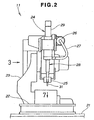
- the sealant coating station 11 is formed from a separator placement platform 22 attached to a base portion 21, an arm portion 23 attached the base portion 21, a sealant coating gun 24 attached the arm portion 23, and a non-contact type sensor 25 disposed so as to be near to the distal end of the sealant coating gun 24.
- the sealant coating gun 24 is formed from a sealant cartridge 26 which houses a sealant material and which is exchangeable, a sealant supplying hose 27 attached the sealant cartridge 26, a sealant extruding portion 28 to which the distal end of the sealant supplying hose 27 is connected, an electric motor 29 driving the sealant extruding portion 28, and a nozzle portion 31 attached to the distal end of the sealant extruding portion 28 for discharging sealant.
- the non-contact type sensor 25 is a sensor which senses, in a state of non-contact, the sealant, which was previously coated in the midst of coating the sealant on the separator by irradiating, for example, a laser onto a separator surface which is substantially below the nozzle portion 31.
- a control apparatus which is not illustrated drives the arm portion 23 and controls the horizontal movement and the raising-lowering of the sealant coating gun 24.
- the sealant extruding portion 28 of the sealant coating gun 24 is structured such that a screw at which a spiral groove is provided is inserted in a cylinder, and sucks the sealant in the sealant cartridge 26 via the sealant supplying hose 27 by rotating the screw by the electric motor 29, and extrudes the sealant between the inner wall of the cylinder and the groove of the screw, and discharges the sealant from the nozzle portion 31. Further, as will be described later, the sealant extruding portion 28 pushes the sealant up between the inner wall of the cylinder and the groove of the screw, and sucks the sealant from the nozzle portion 31, by rotating the screw in a direction opposite to the above direction.
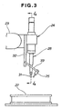
- a backing-plate 32 is attached to the rear portion of the sealant coating gun 24.
- Stays 33, 33 are extended in an oblique direction from the lower end of the backing-plate 32.
- the non-contact type sensor 25 is attached to the distal ends of these stays 33, 33.
- the distal end of the non-contact type sensor 25 is directed downward of the nozzle portion 31.
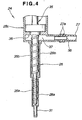
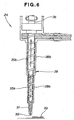
- a first cylinder portion 28a and a second cylinder portion 28b are provided at the sealant extruding portion 28 of the sealant coating gun 24.
- a sealant extruding shaft 35 in which a first screw 35a and a second screw 35b are respectively inserted in these first cylinder portion 28a and second cylinder portion 28b, is connected to an output shaft of the electric motor 29 (refer to Fig. 3).
- reference numerals 27a, 27a denote hose bands
- reference numeral 28c denotes a case portion which is integrally formed with the second cylinder portion 28b
- reference numeral 36 denotes a bearing portion provided for supporting the sealant extruding shaft 35 at the case portion 28c
- reference numeral 37 denotes a sealant introducing room formed at the case portion 28c for communicating with the sealant supplying hose 27, and reference numeral 38 denotes a joint.
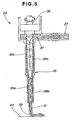
- the sealant extruding shaft 35 is rotated in the direction of the outlined arrow by operating the electric motor.
- the rotating direction of the electric motor and the sealant extruding shaft 35 here is the forward direction (is forward rotation).
- the sealant 39 sucked into the sealant introduction room 37 via the sealant supplying hose 27 from the sealant cartridge is, as shown by the arrows, extruded downward from between the first cylinder 28a and the groove of the first screw 35a, and between the second cylinder 28a and the groove of the second screw 35b, and is discharged from the nozzle portion 31 to the exterior, and is coated on the separator 40.
- the electric motor is rotated in a direction opposite to the rotating direction shown in Fig. 5, and the sealant extruding shaft 35 is rotated in the direction of the outlined arrow as shown in Fig. 6.
- the rotating directions of the electric motor and the sealant extruding shaft 35 are inverse directions (are inverse rotations).
- the sealant 39 between the first cylinder portion 28a and the groove of the first screw 35a and the sealant 39 between the second cylinder portion 28b and the groove of the second screw 35b are moved upward, and the sealant 39 in the nozzle portion 31 is sucked.
- the separator placement platform 22 of the sealant coating station 11 has pallet placement platforms 41, 42, 43, 44 on which pallets (to be described later) which convey the separator are placed, a first positioning member 45 and a second positioning member 46 which are for positioning the pallets on the separator placement platform 22, and straightening devices 47, 47 for straightening warping of the separator placed on the pallet.
- the pallet placement portion 41 has a placement surface 51 and an L-shaped convex portion 52 which is made to project from the placement surface 51, and the L-shaped convex portion 52 is a member at which positioning surfaces 52a, 52b are formed.
- the pallet placement portion 42 has a placement surface 53 and a rectangular convex portion 54 which is made to project from the placement surface 53, and the rectangular convex portion 54 is a member at which a positioning surface 54a is formed.
- the pallet placement portions 43, 44 have placement surfaces 55, 56.
- the first positioning member 45 is formed from a cylinder portion 61, rods 62, 62 inserted in unillustrated cylinders in the cylinder portion 61, and a pressing portion 63 attached to the distal ends of these rods 62, 62.
- the first positioning member 45 pushes the rods 62, 62 out by supplying oil or air from intake openings 64, 64 into the cylinders, and presses a portion of the above-described pallet by the pressing portion 63, and positions the pallet.
- reference numeral 63a is an inclined surface provided at the pressing portion 63.
- the second positioning member 46 is formed from a cylinder portion 66; rods 67, 67 inserted in unillustrated cylinders in the cylinder portion 61, and a pressing portion 68 attached to the distal ends of these rods 67, 67.
- the second positioning member 46 pushes the rods 67, 67 out by supplying oil or air from intake openings 69, 69 into the cylinders, and presses a portion of the above-described pallet by the pressing portion 68, and positions the pallet.
- reference numeral 68a is an inclined surface provided at the pressing portion 68.
- the straightening device 47 is formed from a cylinder portion 72, a joint pipe 75 connected to jet holes 74 ... (here and hereafter, ... denotes a plurality of) which are formed on the cylinder portion 72 and which open at the rim of the top surface 73, and an air hose 76 connected to the joint pipe 75.
- Fig. 8B if compressed air is supplied from the air hose 76 and is jetted to the exterior via the joint pipe 75 and the nozzles 74 ..., when the separator 40 is made to approach the straightening device 47, the air powerfully flows out from between the rim of the pillar portion 72 and the separator 40 as shown by arrows (1), (1). In accordance therewith, because negative pressure arises between the central portion of the top surface 73 of the pillar portion 72 and the separator 40, the separator 40 is sucked toward the cylindrical portion 72 side as per arrow (2). However, due to blowing out of the air from the nozzles 74 ..., the separator 40 does not stick to the top surface 73 of the cylindrical portion 72.
- the straightening apparatus 47 can suck the separator 40 in a state of being separated from the separator 40 without contacting the separator 40, and can straighten the warping of the separator 40.
- metal ions adhere to the separator 40, the metal ions adhere to the carbon electrode of the MEA laminated on the separator 40, and the metal ions and electrons bond, and metal precipitates on the carbon electrode. In accordance therewith, there are cases in which the precipitated metal prevents hydrogen and oxygen from reacting and reduces the performance of the fuel cell.
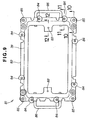
- a pallet 81 serving as a conveying member is structured such that positioning pins 83, 83 for positioning the separator 40, hooks 84 ... for fixing the separator 40, and positioning blocks 85 ... for positioning on the aforementioned separator placement platform 22 (refer to Fig. 7) are attached to a frame body 82.
- reference numerals 86, 86 are handholds.
- Fig. 10 shows attachment of the positioning block 85 to the bottom surface of the frame body 82 by a screw 91.
- the positioning block 85 is a substantially cylindrical member.
- the hook 84 is structured such that a separator fixing piece 94 and a collar 95 are attached on the top surface of the frame body 82 by a bolt 93.
- reference numeral 94 a is a notch provided at the bottom surface portion of the separator fixing piece 94 for catching on the rim of the separator 40.
- Fig. 12 shows a state in which the positioning pin 83 is driven into the top surface of the frame body 82 and the positioning hole 40a of the separator 40 is fitted into the positioning pin 83.
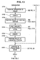
- Fig. 13 shows a flowchart of sealant coating and laminating of the separator for a fuel cell relating to the present invention. Note that STxx denotes the step number.
- the positioning holes 40a, 40a of the separator 40 are fitted into the positioning pins 83, 83 of the pallet 81, and the separator 40 is positioned at the pallet 81.
- the respective positioning blocks 85 are placed on the pallet placement portions 41, 42, 43, 44 of the separator placement platform 22.
- the positioning block 85 is in a state of being placed on the placement surface 51 so as to be separated from the positioning surfaces 52a, 52b of the L-shaped convex portion 52.
- the positioning block 85 is in a state of being placed on the placement surface 53 so as to be separated from the positioning surface 54a of the rectangular convex portion 54.
- the positioning block 85 moves toward the left side and the upper side as shown by the arrows, by receiving components of force in the left direction and the upward direction which are received from the inclined surface 63a in the drawing.
- the positioning block 85 moves toward the left side and the upper side as shown by the arrows by receiving components of force in the left direction and the upward direction in the drawing which are received from the inclined surface 63a.
- Fig. 16C and Fig. 16D if moving of the pressing portions 63, 68 is continued, the positioning block 85 of Fig. 16A contacts the positioning surfaces 52a, 52b by the inclined surfaces 63a, 68a, and the positioning block 85 of Fig. 16B contacts the positioning surface 54a.
- C exists as a clearance amount between a side surface 63b of the pressing portion 63 and the positioning block 85.
- the positioning block 85 is supported by three points of the positioning surfaces 52a, 52b and the inclined surface 63a.
- the positioning blocks 85, 85 which are respectively placed on the placement surface 55 of the pallet placement portion 43 and the placement surface 56 of the pallet placement portion 44, which are shown in Fig. 15, integrally move with the positioning blocks 85, 85 placed on the placement surfaces 51, 53 which were described above.
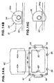
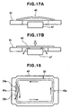
- Fig. 17A shows a state in which the straightening device 47 is arranged below the separator 40 placed on the pallet 81. (One straightening device 47 among the two straightening devices 47 is omitted for convenience.)
- Fig. 17B in order to straighten the warping of the separator 40, compressed air is supplied to the straightening device 47, and the air is jetted from between the straightening device 47 and the separator 40 to the exterior as shown by the arrows, and the straightening device 47 sucks the separator 40.
- the separator 40 is made to be flat as shown by the outlined arrow.
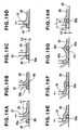
- the sealant 39 starts to coat the sealant 39 from a vicinity of the positioning hole 40a (reference numeral 39a is a coating-start portion), and coats the sealant 39 in a rectangular shape as shown by the arrows at the inner side along the rim of the separator 40 and so as to make a coating-end portion 39b intersect the coating-start portion 39a and overlap them.
- the nozzle portion 31 of the sealant coating gun moves while coating the sealant 39 on the separator 40, while maintaining a height h1 from the separator 40 (namely, it is a predetermined clearance between the separator 40 and the nozzle portion 31 of the sealant coating gun).
- nozzle portion 31 when the nozzle portion 31 approaches the coating-start portion 39a of the sealant 39 and a laser 99 emitted from the non-contact type sensor senses the coating-start portion 39a of the sealant 39, the nozzle portion 31 starts to descend as shown by the arrow.
- nozzle portion 31 descends up to a position of a height h2 from the separator 40, the nozzle portion 31 starts to ascends as shown by the arrow.
- the nozzle portion 31 continues to coat the sealant 39 while horizontally moving, and ends the coating of the sealant 39 in Fig. 19G.
- Aspace 101 exists at the left side (the side behind the intersection) of the coating-start portion 39a at an intersection portion 39c between the coating-start portion 39a and the coating-end portion 39b shown in Fig. 19G. However, there is no space at a portion at the right side (the side in front of the intersection) of the coating-start portion 39a, and the sealability can be improved.
- the laminating station has the separator placement platform which is the same as the separator placement platform 22 shown in Fig. 7, in the same way as described in Fig. 15 and Fig. 16A through Fig. 16D, the pallet 81 is positioned on the separator placement platform of the laminating station.
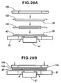
- Fig. 20A compressed air is supplied to the straightening device 47 provided at the laminating station, and the air is jetted from between the straightening device 47 and the separator 40 whose warping has returned as shown by the arrows, and the straightening device 47 sucks the separator 40. As a result, the separator 40 is made to be flat.
- an MEA 103 is placed on the surface of the separator 40 on which the sealant 39 is coated, and further, another separator 104 on which the sealant 39 was coated in advance is placed on the MEA 103, and a frame member 105 is further placed on the separator 104.
- a cell is completed by pressing the overlapped separator 40, the MEA 103, and the separator 104, as shown by the arrows, by a press device 107 shown in Fig. 1 via the frame member 105.
- Fig. 21 shows a state in which an unillustrated gas flow path and water flow path are formed at the separator 40, and a sealant coating groove 118 is provided at the periphery of these gas flow path and water flow path, and the sealant 39 is coated in the sealant coating groove 118.
- the sealant coating groove 118 is a circular groove in plan view which has an extension portion 122 whose width is greater than other portions. Given that the groove width of the extension portion 122 is w1 and the groove width of the portions other than the extension portion 122 is w2, w1 > w2.
- the sealant 39 is coated as the straight shaped coating-start portion 39a at the extension portion 122 of the seal groove 118, and is coated in order from the coating-start portion 39a, as a first curved portion 124, a first straight portion 125, a second curved portion 126, a second straight portion 127, and a third curved portion 128, and is coated as the straight shaped coating-end portion 39b following the third curved portion 128 at the extension portion 122.
- reference numeral 132 denotes a movement route along which the sealant coating gun 24 horizontally moves without coating the sealant 39
- reference numerals 140 through 148 denote imaginary points provided on the sealant coating groove 118 in Fig. 21 for being a starting point or an ending point of movement of the sealant coating gun 24 when the respective portions of the sealant 39 are coated.
- Reference numeral 151 denotes a point on the first curved portion 124
- reference numeral 152 denotes a point of the first straight portion 125
- reference numeral 153 denotes a point on the second curved portion 126
- reference numeral 154 denotes a point on the second straight portion 127
- reference numeral 155 denotes a point on the third curved portion 128.
- the points 151, 153, 155 which were described above are teaching points which teach the moving direction in advance.
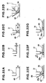
- the distal end of the nozzle portion 31 is disposed so as to be separated by a predetermined distance d1 from the separator 40.
- nozzle portion 31 is made to descend by a predetermined distance d2 from the position of Fig. 22A, and coating of the sealant is started.
- the nozzle portion 31 is made to ascend up to a position (a) at a predetermined velocity v1.
- Fig. 22D the sealant 39 is coated on the separator 40 while horizontally moving the nozzle portion 31 at a predetermined velocity v2. At this time, the laser 99 is irradiated onto the separator 40 from the non-contact type sensor.
- Fig. 23 explains the other example of operation of the sealant coating gun relating to the present invention.
- STxx denotes step numbers.
- a seal groove in which a sealant is coated is provided in a separator of a fuel cell, and widths of the seal groove at a coating-start portion and a coating-end portion of the sealant are made to be greater than portions other than these coating-start portion and coating-end portion, and the coating-start portion and coating-end portion of the sealant are made to intersect at a place at which the width of the seal groove is made large.
- adhesion between the coating-start portion and the coating-end portion can be improved, and because they are made to intersect at a place at which the seal groove is made large, the degrees of freedom of the coated position of the sealant can be increased and the sealability is improved. Accordingly, the present invention is useful for manufacturing a fuel cell.
Landscapes
- Life Sciences & Earth Sciences (AREA)
- Engineering & Computer Science (AREA)
- Manufacturing & Machinery (AREA)
- Sustainable Development (AREA)
- Sustainable Energy (AREA)
- Chemical & Material Sciences (AREA)
- Chemical Kinetics & Catalysis (AREA)
- Electrochemistry (AREA)
- General Chemical & Material Sciences (AREA)
- Fuel Cell (AREA)
Abstract
Description
Claims (6)
- A method for coating a sealant on a separator for a fuel cell, in which a liquid sealant is coated at a periphery of a gas flow path and a water flow path of the separator by using sealant coating means which comprises a motor, sealant extruding means driven by the motor, and a nozzle portion provided at a distal end of the sealant extruding means, the method comprising the steps of:forming on the separator a sealing groove with the sealant coated therein;widths of the sealing groove at coating-start portion and coating-end portion of the sealant are made to be greater than widths of portions other than the coating-start portion and the coating-end portion, and the coating-start portion and the coating-end portion of the sealant are made to intersect at a place where the width of the sealing groove is made large.
- A method for coating a sealant on a separator for a fuel cell according to claim 1, wherein, at the sealant coating-end portion, before an end of coating, a horizontal moving velocity of the nozzle portion is made to be a low velocity and a sealant coating amount is reduced.
- A method for coating a sealant on a separator for a fuel cell according to claim 1, wherein the means for coating a sealant is raising-lowering controlled so as to run along an outer periphery of the sealant at a point in time when the distal end of the means for coating a sealant has approached the coating-start portion of the sealant.
- A method for coating a sealant on a separator for a fuel cell according to claim 3, wherein a non-contact type sensor is additionally provided at the means for coating a sealant, and the raising-lowering control is started by detecting the coating-start portion of the sealant by the non-contact type sensor.
- A method for coating a sealant on a separator for a fuel cell according to claim 1, wherein means for straightening which straightens warping of the separator is additionally provided at a sealant coating station which coats the sealant on the separator, and the sealant is coated on the separator while straightening warping of the separator by the means for straightening.
- A method for coating a sealant on a separator for a fuel cell according to claim 5, wherein negative pressure generated at the means for straightening is controlled such that a clearance between the separator and the means for coating a sealant becomes a predetermined clearance.
Applications Claiming Priority (7)
| Application Number | Priority Date | Filing Date | Title |
|---|---|---|---|
| JP2001206742 | 2001-07-06 | ||
| JP2001206742A JP4402324B2 (en) | 2001-07-06 | 2001-07-06 | Method for correcting warpage of separator for fuel cell, device for correcting warpage, and method for applying sealing material |
| JP2001206639 | 2001-07-06 | ||
| JP2001206639A JP4402323B2 (en) | 2001-07-06 | 2001-07-06 | Method of applying sealing material for fuel cell separator |
| JP2001211333 | 2001-07-11 | ||
| JP2001211333A JP4922505B2 (en) | 2001-07-11 | 2001-07-11 | Method for applying sealing material for fuel cell separator |
| PCT/JP2002/006694 WO2003005469A1 (en) | 2001-07-06 | 2002-07-02 | Sealing material coating method for fuel cell-use separator |
Publications (3)
| Publication Number | Publication Date |
|---|---|
| EP1416554A1 true EP1416554A1 (en) | 2004-05-06 |
| EP1416554A4 EP1416554A4 (en) | 2007-12-05 |
| EP1416554B1 EP1416554B1 (en) | 2010-06-23 |
Family
ID=27347102
Family Applications (1)
| Application Number | Title | Priority Date | Filing Date |
|---|---|---|---|
| EP02743780A Expired - Lifetime EP1416554B1 (en) | 2001-07-06 | 2002-07-02 | Method for coating a sealant on a fuel cell separator |
Country Status (7)
| Country | Link |
|---|---|
| US (1) | US7226635B2 (en) |
| EP (1) | EP1416554B1 (en) |
| KR (1) | KR100836802B1 (en) |
| CN (1) | CN1282270C (en) |
| CA (1) | CA2451096C (en) |
| DE (1) | DE60236804D1 (en) |
| WO (1) | WO2003005469A1 (en) |
Cited By (1)
| Publication number | Priority date | Publication date | Assignee | Title |
|---|---|---|---|---|
| US8310157B2 (en) | 2008-09-10 | 2012-11-13 | General Electric Company | Lamp having metal conductor bonded to ceramic leg member |
Families Citing this family (11)
| Publication number | Priority date | Publication date | Assignee | Title |
|---|---|---|---|---|
| KR100537726B1 (en) * | 2003-06-02 | 2005-12-19 | (주)퓨얼셀 파워 | A sealing structure for polymer electrolyte fuel cell |
| KR100528339B1 (en) * | 2003-10-01 | 2005-11-15 | 삼성에스디아이 주식회사 | Direct liquid feed fuel cell stack |
| JP5038586B2 (en) * | 2004-04-30 | 2012-10-03 | トヨタ自動車株式会社 | Fuel cell separator, separator joining method, fuel cell |
| KR100760219B1 (en) * | 2005-08-01 | 2007-10-05 | 연세대학교 산학협력단 | Method for manufacturing electrochemical cell by robo dispensing, its urea material paste, and solid oxide fuel cell produced thereby |
| US20100233369A1 (en) * | 2009-02-16 | 2010-09-16 | Esec Ag | Method Of Forming A Paste Pattern |
| US8911918B2 (en) * | 2010-02-08 | 2014-12-16 | GM Global Technology Operations LLC | Hybrid seal application process |
| JP5166468B2 (en) * | 2010-03-23 | 2013-03-21 | 株式会社東芝 | Paste coating apparatus and paste coating method |
| DE102013206283A1 (en) * | 2013-04-10 | 2014-10-16 | Elringklinger Ag | Method of applying coating material and applicator |
| JP7120119B2 (en) * | 2019-03-29 | 2022-08-17 | 日本電産株式会社 | LIQUID APPLICATION METHOD, LIQUID APPLICATOR AND LIQUID GASKET |
| CN110010923B (en) * | 2019-04-01 | 2021-06-25 | 清华大学 | A kind of manufacturing method of integrated sealed stack |
| CN112593639A (en) * | 2020-12-17 | 2021-04-02 | 贵州电网有限责任公司 | Weather-proof high-pressure sealing structure for joint of steel tower |
Family Cites Families (13)
| Publication number | Priority date | Publication date | Assignee | Title |
|---|---|---|---|---|
| JPS61216250A (en) * | 1985-03-22 | 1986-09-25 | Hitachi Ltd | Fuel cell |
| JPS6343264A (en) * | 1986-08-07 | 1988-02-24 | Mitsubishi Electric Corp | Fuel cell |
| US5083161A (en) | 1989-08-25 | 1992-01-21 | Xerox Corporation | Densitometer for measuring developability |
| JPH05231546A (en) * | 1991-03-07 | 1993-09-07 | Fanuc Ltd | Method for controlling flow of sealant in sealing by industrial robot |
| JP2569361Y2 (en) * | 1991-12-18 | 1998-04-22 | 本田技研工業株式会社 | Fuel cell separator |
| JP3237544B2 (en) | 1996-10-11 | 2001-12-10 | 富士通株式会社 | Manufacturing method of flat display panel and flat display panel |
| JP2000123848A (en) | 1998-10-19 | 2000-04-28 | Honda Motor Co Ltd | Fuel cell |
| JP2000188118A (en) * | 1998-12-24 | 2000-07-04 | Mitsubishi Plastics Ind Ltd | Packing material for polymer electrolyte fuel cell separator |
| JP2000231927A (en) * | 1999-02-09 | 2000-08-22 | Mitsubishi Plastics Ind Ltd | Polymer electrolyte fuel cell separator |
| JP3456935B2 (en) * | 2000-01-12 | 2003-10-14 | タイガースポリマー株式会社 | Method of forming sealing material for fuel cell |
| CA2345852C (en) * | 2000-05-02 | 2008-11-18 | Honda Giken Kogyo Kabushiki Kaisha | Fuel cell having sealant for sealing a solid polymer electrolyte membrane |
| US20050095492A1 (en) * | 2001-05-15 | 2005-05-05 | Hydrogenics Corporation | Fuel cell stack |
| US6777127B2 (en) * | 2001-06-22 | 2004-08-17 | Ballard Power Systems Inc. | Systems, apparatus and methods for bonding and/or sealing electrochemical cell elements and assemblies |
-
2002
- 2002-07-02 EP EP02743780A patent/EP1416554B1/en not_active Expired - Lifetime
- 2002-07-02 WO PCT/JP2002/006694 patent/WO2003005469A1/en not_active Ceased
- 2002-07-02 US US10/482,467 patent/US7226635B2/en not_active Expired - Lifetime
- 2002-07-02 CN CNB028136195A patent/CN1282270C/en not_active Expired - Fee Related
- 2002-07-02 CA CA2451096A patent/CA2451096C/en not_active Expired - Fee Related
- 2002-07-02 KR KR1020047000084A patent/KR100836802B1/en not_active Expired - Fee Related
- 2002-07-02 DE DE60236804T patent/DE60236804D1/en not_active Expired - Lifetime
Cited By (1)
| Publication number | Priority date | Publication date | Assignee | Title |
|---|---|---|---|---|
| US8310157B2 (en) | 2008-09-10 | 2012-11-13 | General Electric Company | Lamp having metal conductor bonded to ceramic leg member |
Also Published As
| Publication number | Publication date |
|---|---|
| CA2451096C (en) | 2010-09-28 |
| US7226635B2 (en) | 2007-06-05 |
| CN1524306A (en) | 2004-08-25 |
| US20040191409A1 (en) | 2004-09-30 |
| CA2451096A1 (en) | 2003-01-16 |
| KR20040007767A (en) | 2004-01-24 |
| DE60236804D1 (en) | 2010-08-05 |
| EP1416554A4 (en) | 2007-12-05 |
| KR100836802B1 (en) | 2008-06-10 |
| EP1416554B1 (en) | 2010-06-23 |
| WO2003005469A1 (en) | 2003-01-16 |
| CN1282270C (en) | 2006-10-25 |
Similar Documents
| Publication | Publication Date | Title |
|---|---|---|
| CA2451096C (en) | Sealing material coating method for fuel cell-use separator | |
| KR101610457B1 (en) | Fuel cell stack manifold with ejector function | |
| EP1416555B1 (en) | Method of coating fuel cell separator with seal material | |
| JP4383008B2 (en) | Fuel cell separator, method of laminating membrane / electrode assembly, and laminating apparatus | |
| CN116921858B (en) | Laser welding and coding equipment for power battery cover plate | |
| CN102148383B (en) | Hybrid seal application process | |
| JP4402323B2 (en) | Method of applying sealing material for fuel cell separator | |
| JP4402324B2 (en) | Method for correcting warpage of separator for fuel cell, device for correcting warpage, and method for applying sealing material | |
| JP4922505B2 (en) | Method for applying sealing material for fuel cell separator | |
| CN100427220C (en) | Method for coating a sealant on a separator for a fuel cell | |
| CN115229387B (en) | Converging welding device of battery module | |
| JP4132735B2 (en) | Pallet positioning method and separator for fuel cell separator | |
| CN116037731A (en) | Lug turnover improving device and method and battery production equipment | |
| JP4934250B2 (en) | Method for applying sealing material for fuel cell separator | |
| JP2003031238A (en) | Method of applying sealant for fuel cell separator | |
| CN224240278U (en) | Forming device and fuel cell bipolar plate sealing structure forming system | |
| CN119408971B (en) | Transport and stacking system and method for flow channel electrode plates | |
| JP2003031233A (en) | Method of applying sealant for fuel cell separator |
Legal Events
| Date | Code | Title | Description |
|---|---|---|---|
| PUAI | Public reference made under article 153(3) epc to a published international application that has entered the european phase |
Free format text: ORIGINAL CODE: 0009012 |
|
| 17P | Request for examination filed |
Effective date: 20040123 |
|
| AK | Designated contracting states |
Kind code of ref document: A1 Designated state(s): AT BE BG CH CY CZ DE DK EE ES FI FR GB GR IE IT LI LU MC NL PT SE SK TR |
|
| AX | Request for extension of the european patent |
Extension state: AL LT LV MK RO SI |
|
| A4 | Supplementary search report drawn up and despatched |
Effective date: 20071107 |
|
| 17Q | First examination report despatched |
Effective date: 20081105 |
|
| GRAP | Despatch of communication of intention to grant a patent |
Free format text: ORIGINAL CODE: EPIDOSNIGR1 |
|
| RTI1 | Title (correction) |
Free format text: METHOD FOR COATING A SEALANT ON A FUEL CELL SEPARATOR |
|
| RAP1 | Party data changed (applicant data changed or rights of an application transferred) |
Owner name: HONDA GIKEN KOGYO KABUSHIKI KAISHA |
|
| GRAS | Grant fee paid |
Free format text: ORIGINAL CODE: EPIDOSNIGR3 |
|
| GRAA | (expected) grant |
Free format text: ORIGINAL CODE: 0009210 |
|
| AK | Designated contracting states |
Kind code of ref document: B1 Designated state(s): DE FR GB |
|
| REF | Corresponds to: |
Ref document number: 60236804 Country of ref document: DE Date of ref document: 20100805 Kind code of ref document: P |
|
| PGFP | Annual fee paid to national office [announced via postgrant information from national office to epo] |
Ref country code: FR Payment date: 20100805 Year of fee payment: 9 |
|
| PGFP | Annual fee paid to national office [announced via postgrant information from national office to epo] |
Ref country code: GB Payment date: 20100913 Year of fee payment: 9 |
|
| PLBE | No opposition filed within time limit |
Free format text: ORIGINAL CODE: 0009261 |
|
| STAA | Information on the status of an ep patent application or granted ep patent |
Free format text: STATUS: NO OPPOSITION FILED WITHIN TIME LIMIT |
|
| 26N | No opposition filed |
Effective date: 20110324 |
|
| REG | Reference to a national code |
Ref country code: DE Ref legal event code: R097 Ref document number: 60236804 Country of ref document: DE Effective date: 20110323 |
|
| PGFP | Annual fee paid to national office [announced via postgrant information from national office to epo] |
Ref country code: DE Payment date: 20110629 Year of fee payment: 10 |
|
| GBPC | Gb: european patent ceased through non-payment of renewal fee |
Effective date: 20110702 |
|
| REG | Reference to a national code |
Ref country code: FR Ref legal event code: ST Effective date: 20120330 |
|
| PG25 | Lapsed in a contracting state [announced via postgrant information from national office to epo] |
Ref country code: FR Free format text: LAPSE BECAUSE OF NON-PAYMENT OF DUE FEES Effective date: 20110801 |
|
| PG25 | Lapsed in a contracting state [announced via postgrant information from national office to epo] |
Ref country code: GB Free format text: LAPSE BECAUSE OF NON-PAYMENT OF DUE FEES Effective date: 20110702 |
|
| PG25 | Lapsed in a contracting state [announced via postgrant information from national office to epo] |
Ref country code: DE Free format text: LAPSE BECAUSE OF NON-PAYMENT OF DUE FEES Effective date: 20130201 |
|
| REG | Reference to a national code |
Ref country code: DE Ref legal event code: R119 Ref document number: 60236804 Country of ref document: DE Effective date: 20130201 |