EP1416381A1 - System and method for preserving state data of a personal computer in a standby state in the event of an ac power failure - Google Patents
System and method for preserving state data of a personal computer in a standby state in the event of an ac power failure Download PDFInfo
- Publication number
- EP1416381A1 EP1416381A1 EP20030023262 EP03023262A EP1416381A1 EP 1416381 A1 EP1416381 A1 EP 1416381A1 EP 20030023262 EP20030023262 EP 20030023262 EP 03023262 A EP03023262 A EP 03023262A EP 1416381 A1 EP1416381 A1 EP 1416381A1
- Authority
- EP
- European Patent Office
- Prior art keywords
- computer
- power
- state
- energy storage
- storage medium
- Prior art date
- Legal status (The legal status is an assumption and is not a legal conclusion. Google has not performed a legal analysis and makes no representation as to the accuracy of the status listed.)
- Granted
Links
Images


Classifications
-
- G—PHYSICS
- G06—COMPUTING; CALCULATING OR COUNTING
- G06F—ELECTRIC DIGITAL DATA PROCESSING
- G06F1/00—Details not covered by groups G06F3/00 - G06F13/00 and G06F21/00
- G06F1/26—Power supply means, e.g. regulation thereof
- G06F1/30—Means for acting in the event of power-supply failure or interruption, e.g. power-supply fluctuations
- G06F1/305—Means for acting in the event of power-supply failure or interruption, e.g. power-supply fluctuations in the event of power-supply fluctuations
-
- G—PHYSICS
- G06—COMPUTING; CALCULATING OR COUNTING
- G06F—ELECTRIC DIGITAL DATA PROCESSING
- G06F1/00—Details not covered by groups G06F3/00 - G06F13/00 and G06F21/00
- G06F1/26—Power supply means, e.g. regulation thereof
- G06F1/30—Means for acting in the event of power-supply failure or interruption, e.g. power-supply fluctuations
Definitions
- This invention relates generally to power management of a computer, and more particularly to a mechanism that enables a simple power on/off model for a personal computer that uses a volatile standby state as the default "off" state to provide an "instant-on" user experience while preserving user and system state in the event of an AC power failure.
- a computer typically has a power button on its housing (e.g., on its front panel) that a user can press to initiate a power-up or power-down operation of the computer.
- a power button on its housing (e.g., on its front panel) that a user can press to initiate a power-up or power-down operation of the computer.
- many modem personal computers implement power-saving states defined in the Advanced Configuration and Power Interface (ACPI) specification.
- ACPI Advanced Configuration and Power Interface
- the power button may be used to bring the computer from the normal working (i.e., "on") state to one of the power-saving states in which the computer is partially powered, such as the S1-S3 states of the ACPI, or to a power-down state, such as the S4 or S5 state of the ACPI.
- the computer can quickly return to the "on” state (under 2 seconds), while if it is in the "off” state a long time will be required for the computer to boot back up to the "on” state (15-45 seconds).
- the different ways the computer may respond to the pressing of the same power button can create an inconsistent and confusing user experience. This is in sharp contrast to normal home appliances, such as a stereo system or a television, that have simple on/off states.
- One possible way to implement a simple on/off model in a personal computer is to select an intermediate power-saving state, such as the S3 "standby" state of the ACPI specification, as the default “off” state.
- an intermediate power-saving state such as the S3 "standby" state of the ACPI specification
- the computer system goes into the standby state instead of completely powering down (the ACPI S5 state).
- the power button to turn the computer back on the computer wakes from the standby state and resumes the working state (the ACPI S0 state).
- an important advantage of this simple power on/off model is that the computer can quickly transition from the standby state to the working state, thus providing an "instant-on" experience.
- a standby state is typically a volatile state in the sense that the system and user state data are not persistently stored (e.g., on the hard drive) when the system transitions from the working state into the standby state. If the computer is in a standby state and the AC power fails or is interrupted, or the computer is accidentally unplugged, the computer will lose its user and system state data and other data held in the RAM (e.g., open and unsaved documents and files) if they were not saved prior to the AC power loss. When the AC power returns, the computer will have to boot up and cannot return to the previous user state it was in prior to the AC power failure. As a result, the user has to re-start all of the applications that were previously running prior to the AC power failure.
- the RAM e.g., open and unsaved documents and files
- the present invention provides a mechanism for preserving user and system state data of a personal computer in the event of an AC power loss when the computer is in a standby state.
- This mechanism uses an energy storage medium, such as a battery, for powering the operations or the computer when the AC power fails.
- a switchover circuit connects the DC output voltage of the energy storage medium to the computer power supply for powering the internal components of computer but not the external peripheral devices, and the computer is waken up and returned to the working state.
- a battery driver then issues a critical battery alarm, even though the battery is not at a low voltage level.
- the critical battery alarm triggers the operating system of the computer to perform a transition into a hibernation state, during which the state data of the computer are persistently stored (i.e., stored in a nonvolatile memory to prevent data loss).
- the energy storage medium is then disconnected from the power supply after the computer system has entered hibernation.
- the computer can reboot and restore the state data, and then return to the standby state it was in prior to the AC power loss.
- program modules include routines, programs, objects, components, data structures, etc. that perform particular tasks or implement particular abstract data types.
- program modules include routines, programs, objects, components, data structures, etc. that perform particular tasks or implement particular abstract data types.
- program modules may be practiced with other computer system configurations, including hand-held devices, multi-processor systems, microprocessor-based or programmable consumer electronics, network PCs, minicomputers, mainframe computers, and the like.
- the invention may be practiced in distributed computing environments where tasks are performed by remote processing devices that are linked through a communications network.
- program modules may be located in both local and remote memory storage devices.
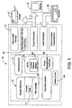
- FIG. 1 an example of a basic configuration for a computer on which all or parts of the invention described herein may be implemented is shown.
- the computer 10 typically includes at least one processing unit 14 and memory 16.
- the processing unit and system memory are typically mounted on a motherboard 18 of the computer 10.
- the processing unit 14 executes instructions to carry out tasks in accordance with various embodiments of the invention.
- the processing unit 14 may transmit electronic signals to other parts of the computer 10 and to devices outside of the computer 10 to cause some results. At least some of these instructions are generated by an operating system 22.
- the operating system 22 may include several user mode and kernel mode programs.
- the memory 16 may be volatile (such as a RAM 17), non-volatile (such as a ROM or flash memory) or some combination of the two.
- computer 10 may also have additional features/functionality.
- computer 10 may also include additional storage (such as a removable storage 21 and/or a non-removable storage, such as a hard drive 23) including, but not limited to, magnetic or optical disks or tape, removable flash memory devices, etc.
- Computer storage media includes volatile and non-volatile, removable and non-removable media implemented in any method or technology for storage of information, including computer-executable instructions, data structures, program modules, or other data.
- Computer storage media includes, but is not limited to, RAM, ROM, EEPROM, flash memory, CD-ROM, digital versatile disk (DVD) or other optical storage, magnetic cassettes, magnetic tape, magnetic disk storage or other magnetic storage devices, or any other medium which can be used to stored the desired information and which can be accessed by the computer 10. Any such computer storage media may be part of computer 10.
- the computer also includes a Basic Input/Output System (BIOS) 26, which is conventionally an essential set of routines in a personal computer.
- BIOS Basic Input/Output System
- the BIOS 26 is typically stored on a chip and provides an interface between the operating system and the hardware.
- the BIOS 26 supports the peripheral technologies and internal services such as the real-time clock (time and date).
- the BIOS 26 tests the system and prepares the computer for operation by querying its own small CMOS memory bank for drive and other configuration settings. It searches for other BIOS's on the plug-in boards and sets up pointers (interrupt vectors) in memory to access those routines. It then loads the operating system and passes control to it.
- the BIOS accepts requests from the drivers as well as the application programs.
- the BIOS 26 is programmed to be part of the mechanism for preserving the state data of the computer in the event of an AC power failure that occurs when the computer is in a standby state.
- the computer 10 further includes a power management controller 36 for supporting different power states, such as the ACPI S1-S5 states.
- the power management controller 36 is typically implemented as firmware in an integrated circuit (IC), which is typically mounted on the motherboard of the computer. As described in greater detail below, in a preferred embodiment, the power management controller 36 is also involved in the mechanism for preserving the state data in response to an AC power failure.
- IC integrated circuit
- the computer 10 may also contain communications connections that allow the device to communicate with other devices.
- a communication connection is an example of a communication medium.
- Communication media typically embodies computer readable instructions, data structures, program modules or other data in a modulated data signal such as a carrier wave or other transport mechanism and includes any information delivery media.
- communication media includes wired media such as a wired network or direct-wired connection, and wireless media such as acoustic, RF, infrared and other wireless media.
- the term "computer-readable medium" as used herein includes both computer storage media and communication media.
- the computer 10 may also have input devices such as a keyboard 25, mouse, pen, voice input device, touch input device, etc.
- Output devices such as a display 20, speakers, a printer 27, etc. may also be included. The general operations of all these devices are well known in the art and need not be discussed at length here.
- the present invention is directed to a mechanism for preserving the system and user state data of a desktop computer when an AC power failure occurs while the computer is in a standby state.
- This mechanism enables the computer to implement a simple on/off user model that uses a volatile standby state as its default "off” state so as to provide an "instant-on" experience.
- the term "standby state” means a power-saving state that provides at least the electrical power needed to preserve contents of the RAM of the computer and to watch for a wake-up event. This term is also intended to be interchangeable with the term “sleep state.”
- the standby state is the S3 state defined by the Advanced Configuration and Power Interface (ACPI) specification.
- ACPI Advanced Configuration and Power Interface
- the computer 10 when the computer 10 is in the working or "on” state (e.g., the S0 state of the ACPI specification) and the user presses the power button 50 to "turn off” the computer, the computer is not really turned off in the sense that it is completely powered off (e.g., the ACPI S5 state). Instead, the computer is put into the standby mode that preserves the system state in the RAM. When the user later presses the power button to turn the computer on, the computer wakes from the standby state and resumes the working state.
- the working or "on” state e.g., the S0 state of the ACPI specification
- the standby state corresponds to the S3 state of the ACPI specification.
- the S3 state which is also often called the “suspend to RAM” state, is a relatively deep power-saving mode. In this mode, most components of the computer, including the CPU and the cache, are shut down except for a small amount of power needed to keep the contents of the RAM of the computer from fading away, and to keep the power management controller 36 on to listen for a wake-up event.
- the power button event signal generated by the power button is routed to the power management controller 36, which then sends a wake signal to wake the system.
- pressing the power button is not the only event that may wake up the computer from the standby state.
- other events such as receiving a special kind of LAN packet or an inbound modem call, can also trigger a wake-up operation, depending on how the system is set up. Such wake events are conventional and need not be described further.
- the personal computer 10 is normally powered by the AC power.
- the computer 10 has a power supply that receives AC power (e.g., 115V at 50/60 Hz) via a power cord that has a plug for plugging into an AC outlet.
- the power supply 76 has an AC-to-DC section 78 that converts the AC voltage into a suitable DC voltage, such as +12V.
- the DC output of the AC-to-DC section 78 is then used as the input for a DC-to-DC section 80 that generates several different DC voltages, such as +12V, +5V, +3.3V, and +5VSB, for powering various components and of the computer system.
- the mechanism of the invention solves this problem by utilizing an energy storage medium to provide the DC power needed by the power supply 76 to generate the DC voltages for operating the computer after the AC power fails.
- the energy storage medium provides a DC output voltage, which is connected to the power supply 76 of the computer for conversion to the DC voltages required to operate the internal components of the computer.
- UPS Uninterruptible Power Supply
- the energy storage medium only powers the necessary components for the operation of preserving the state data, such as the motherboard and the hard drive (and/or the optical drive), and does not power the external peripheral devices (monitor, printer, etc.), which require AC power for operation and are typically plugged into the computer to receive the AC power.
- the energy storage medium may be mounted inside the computer housing, or alternatively may be external to the computer 10 and connected to the power supply 76 of the computer via suitable cabling and connectors.
- the energy storage medium is a battery 70.
- the battery 70 sustains the operation of the computer 10 long enough for the operating system to save the state data and to go to a persistable off state in which the state data are persistently stored (e.g., in a non-volatile memory such as the hard drive) before the battery power is disconnected.
- Such persistable off state may be, for instance, the S4 state of the ACPI specification.
- the computer enters the S4 state (often called the "hibernation" state), it first writes the contents of the RAM 17 and some CPU settings to a special file 64 on the hard drive 23 before shutting the power off. Later, when the computer 10 awakes from hibernation, it does not have to go through a full boot sequence. Instead, after BIOS post, it reads the contents of the data saved in the special file 64 back into the RAM 17, thus restoring itself to the same condition it was in when the hibernation starts.
- the backup battery 70 Since the backup battery 70 only has to sustain the operation of the computer long enough for the computer to enter the persistable off state, the requirement on its power capacity is not great. Also, because the battery may be used many times during the lifetime of the computer, it is preferably rechargeable and reliable. Furthermore, to keep the cost of the computer low, the battery is preferably relatively inexpensive. In one implementation, the backup battery 70 is a sealed lead-acid battery, which meets these requirements. The battery has a suitable voltage, such as 12 volts. It will be appreciated that other types of rechargeable energy storage medium, such as Ni-Cad, Ni-MH, and Li-on batteries, and high-capacity capacitors, may also be used.
- the power supply includes a battery charger circuit 72 and a switchover circuit 86.
- the battery 70 is connected to the switchover circuit 86, which connects the charger 72 to the battery when the power supply 76 receives adequate AC power input.
- the switch-over circuit 86 includes a voltage detection circuit 84 that detects the presence of the AC power as well the voltage of the battery so that it can determine whether there is an AC power failure and whether the DC voltage of the battery is adequately high. When an AC power failure is detected, the switchover circuit 86 connects the battery 70 to the input of the DC-to-DC section 80 of the power supply 76. The DC voltage of the battery 70 is then converted by the DC-to-DC section 80 into the different output DC voltages.
- the switchover circuit 86 is implemented to provide two signals, BATT_OK and ON_BATT.
- the BATT_OK signal indicates whether the battery has enough voltage to support the computer 10 to go through a hibernation sequence.
- the ON_BATT signal indicates whether the system is being powered by the battery 70. This signal is asserted by the power supply 76 when the AC power is not present and the battery 70 has sufficient stored energy as indicated by the BATT_OK signal being asserted high.
- the ON_BATT signal is routed to a general-purpose event (GPE) register 38 on the power management controller 36, which is capable of supplying a wake signal through a system control interrupt (SCI).
- GPE general-purpose event
- the system BIOS 26 implements a control method battery 66 in the ACPI namespace, defining the _BST and _PRW objects.
- the _BST and _PRW objects are actually implemented in a battery driver 68 that is part of the operating system.
- the ON_BATT signal is asserted high due to an AC power failure when the system is in the working state
- the SCI produced by the GPE register 38 is processed by the ACPI driver.
- the _Exx method of the ACPI driver issues a Notify 0x80 to the battery driver 68, which in response runs the _BST object and reports the battery critical flag to the operating system 22 to indicate that the system is in a critical energy state.
- the operating system 22 is configured to enter the hibernation state in response to receiving the critical battery alarm signal.
- the motherboard 18 releases the PS_ON# line of the power supply 76 so that the PS_ON# line goes high. This tells the power supply 76 that the system is in hibernation.
- the switchover circuit 86 returns the ON_BATT signal to "low,” and disconnects the battery 70 from the power supply to preserve the energy of the battery.
- the switch-over circuit 86 connects the DC voltage of the battery 70 to the DC-to-DC section 80 of the power supply so that the system is on battery power, and asserts the ON_BATT high.
- the ON_BATT signal is routed to the GPE 38 on the power management controller 36.
- the _PRW object of the battery driver 68 in the is run to supply the wake signal to the power management controller. As a result, the system wakes to the S0 state. This is indicated by the motherboard's asserting the PS_ON# low.
- the battery driver 68 issues a critical battery alarm, which is routed to the operating system. It should be noted that the critical battery alarm is sent for the purpose of triggering the operating system to enter hibernation and does not indicate the actual battery energy level. Thus, the alarm is sent even though the battery 70 is not at a low energy level.
- the operating system 22 starts the hibernation sequence. When the hibernation is complete, the motherboard 18 releases the PS_ON# line. In response, the power supply 76 disconnects the battery.
- An AC power outage is typically not a single episode of lost power followed by uninterrupted resumption of clean power. Rather, the AC power may flicker on and off for an extended period, such as during a thunderstorm. In that case, if the computer is rebooted every time the AC power returns and goes through the battery-powered shut down process when the AC power goes off again, the battery power may be drained quickly.
- this problem is solved by having the power management controller 36 wait until the AC power is steady for a programmable pre-selected time before waking the system. This prevents the battery power from being consumed by repeatedly putting the system in hibernation while the AC power is unstable. This determination of whether the AC power has been steady long enough may be made by, for example, checking the reading of a hardware timer that starts running when the AC power returns.
- the power supply 76 when the battery power is switched in, the power supply 76 makes power for some of the internal peripheral devices immediately available, but delays the power for other internal peripheral devices.
- the output of the power supply 76 includes "normal power" connectors 108 that provide power immediately after the ON_Batt signal is asserted, and "delayed power" connectors 110 for providing power that is available after a pre-selected time period after the assertion of the ON_BATT signal.
- the delayed power on the connectors 110 becomes valid seven (7) seconds after the power on the normal connectors 108 has become valid.
- this delayed power is to distribute peaks in the load presented to the power supply 76, especially in the case where a peripheral device presents an initial surge in its power demand. For instance, such a surge occurs when an optical disk drive has to spin up.
- the hard disk 23 are connected to the normal peripheral power connectors 108, and optical disks 28 are connected to the delayed peripheral power connectors 110.
- the possible transitions between the power states of the computer system in a preferred embodiment is summarizes in FIG. 4.
- the power management controller instructs the operating system to enter the standby state 92 (e.g., the ACPI S3 state).
- the standby state the computer is still on the AC power. If the user then presses the power button to turn the computer on, the power management controller sends a wake signal to wake the system, and the computer resumes the working state.
- these two transitions are conventional and are standard on personal computers that support the ACPI states.
- the battery power is switched in, and the computer, including the power management controller, is now powered by the battery (the "S3 on battery” state 96).
- the power supply asserts the ON_BATT signal, which causes the power management controller to wake up the computer system from the standby state.
- the computer system goes to the working state powered by the battery (the "S0 on battery” state 98).
- the battery driver 68 then sends a "critical battery alarm” event signal to the operating system.
- the operating system puts the system in the hibernation state (e.g., the ACPI S4 state), with the state data persisted on the hard drive.
- the power supply disconnects the battery to preserve the battery power.
- the entire computer system is in a completely powered-off state 102.
- the computer is set to boot up after a power failure.
- the power management controller now on the AC power, waits for the AC power to be steady for a pre-selected time period and then causes the computer system to return from the full "off" state to the hibernation state (the "S4 on AC power" state 106). Later, the computer system may be waken up from the hibernation state by the power management controller or by the user pressing the power button, and the computer system resumes the working state 90 using the state data stored on the hard drive before the computer entered the hibernation state. Thereafter, the power management controller instructs the operating system to go to the standby state 92.
- the computer immediately resumes the working state 90.
- the computer does not change the way it responses to the power button signal and is able to immediately respond to the pressing of the power button or other triggering events, as if the AC power failure never happened.
- the AC power failure may also occur when the computer is in the working state 90.
- the power of the backup battery immediately switches in, and the computer remains in the working state while being powered by the battery (the state 98).
- the battery driver then sends the "critical battery alarm” event to the operating system, causing the computer to be transitioned to the hibernation state 100, in the same way as described above.
Abstract
Description
- This application claims the priority of U.S. Provisional Application No. 60/422,428, entitled "Method and System for Powering of a Computer with System State Information Preserved in Case of Power Failures," filed October 30, 2002.
- This invention relates generally to power management of a computer, and more particularly to a mechanism that enables a simple power on/off model for a personal computer that uses a volatile standby state as the default "off" state to provide an "instant-on" user experience while preserving user and system state in the event of an AC power failure.
- Powering a computer up and powering it down are basic operations of the computer. To that end, a computer typically has a power button on its housing (e.g., on its front panel) that a user can press to initiate a power-up or power-down operation of the computer. Besides the working state and the power-off states, many modem personal computers implement power-saving states defined in the Advanced Configuration and Power Interface (ACPI) specification. Depending on the power-saving scheme implemented in the computer, the power button may be used to bring the computer from the normal working (i.e., "on") state to one of the power-saving states in which the computer is partially powered, such as the S1-S3 states of the ACPI, or to a power-down state, such as the S4 or S5 state of the ACPI.
- The implementation of a sophisticated power-saving scheme with various power states, however, can turn the task of shutting off a personal computer (PC) into a complicated matter for non-technical users. A user needs to know the differences between the "standby/sleep," "hibernate," and true "off" power states, and to understand the tradeoffs between those different power states. For instance, the user has to decide whether to put the computer into the "off" state that will save data fully but will require a full reboot later, or to put the machine into the standby state that allows the computer to return to the "on" state quickly but does not preserve the state data of the machine if the power fails. In addition, the way a computer is shut down affects the way it responds when the user presses its power button. For instance, if the computer is in the "standby" state, it can quickly return to the "on" state (under 2 seconds), while if it is in the "off" state a long time will be required for the computer to boot back up to the "on" state (15-45 seconds). The different ways the computer may respond to the pressing of the same power button can create an inconsistent and confusing user experience. This is in sharp contrast to normal home appliances, such as a stereo system or a television, that have simple on/off states.
- One possible way to implement a simple on/off model in a personal computer is to select an intermediate power-saving state, such as the S3 "standby" state of the ACPI specification, as the default "off" state. When the user presses the power button to turn the computer "off," the computer system goes into the standby state instead of completely powering down (the ACPI S5 state). When the user presses the power button to turn the computer back on, the computer wakes from the standby state and resumes the working state (the ACPI S0 state). In addition to the simplified and consistent user experience, an important advantage of this simple power on/off model is that the computer can quickly transition from the standby state to the working state, thus providing an "instant-on" experience.
- This simple on/off model, however, has a significant problem. A standby state is typically a volatile state in the sense that the system and user state data are not persistently stored (e.g., on the hard drive) when the system transitions from the working state into the standby state. If the computer is in a standby state and the AC power fails or is interrupted, or the computer is accidentally unplugged, the computer will lose its user and system state data and other data held in the RAM (e.g., open and unsaved documents and files) if they were not saved prior to the AC power loss. When the AC power returns, the computer will have to boot up and cannot return to the previous user state it was in prior to the AC power failure. As a result, the user has to re-start all of the applications that were previously running prior to the AC power failure.
- In view of the foregoing, the present invention provides a mechanism for preserving user and system state data of a personal computer in the event of an AC power loss when the computer is in a standby state. This mechanism uses an energy storage medium, such as a battery, for powering the operations or the computer when the AC power fails. When the computer is in the standby state and the AC power failure occurs, a switchover circuit connects the DC output voltage of the energy storage medium to the computer power supply for powering the internal components of computer but not the external peripheral devices, and the computer is waken up and returned to the working state. A battery driver then issues a critical battery alarm, even though the battery is not at a low voltage level. The critical battery alarm triggers the operating system of the computer to perform a transition into a hibernation state, during which the state data of the computer are persistently stored (i.e., stored in a nonvolatile memory to prevent data loss). The energy storage medium is then disconnected from the power supply after the computer system has entered hibernation. When the AC power returns, the computer can reboot and restore the state data, and then return to the standby state it was in prior to the AC power loss.
-
- FIGURE 1 is a block diagram generally illustrating an exemplary computer system in which the present invention may be implemented;
- FIG. 2 is a schematic diagram of a desktop personal computer having a power button for turning the computer on or off;
- FIG. 3 is a schematic diagram showing components involved in a mechanism in accordance with an embodiment of the invention for providing dependable power for preserving state data to allow system recovery in the event an AC power failure occurs when the computer is in a standby state; and
- FIG. 4 is a schematic diagram showing transitions between power states of the computer in accordance with an embodiment of the invention.
-
- Turning to the drawings, wherein like reference numerals refer to like elements, the invention is illustrated as being implemented in a suitable computing environment. Although not required, the invention will be described in the general context of computer-executable instructions, such as program modules, being executed by a personal computer. Generally, program modules include routines, programs, objects, components, data structures, etc. that perform particular tasks or implement particular abstract data types. Moreover, those skilled in the art will appreciate that the invention may be practiced with other computer system configurations, including hand-held devices, multi-processor systems, microprocessor-based or programmable consumer electronics, network PCs, minicomputers, mainframe computers, and the like. The invention may be practiced in distributed computing environments where tasks are performed by remote processing devices that are linked through a communications network. In a distributed computing environment, program modules may be located in both local and remote memory storage devices.
- The following description begins with a description of a general-purpose computing device that may be used to implement an embodiment of the invention, and the mechanism of the invention for preserving state data in the event of an AC power failure when the computer is in a standby state will be described in greater detail with reference to FIGS. 2-4. Turning now to FIG. 1, an example of a basic configuration for a computer on which all or parts of the invention described herein may be implemented is shown. In its most basic configuration, the
computer 10 typically includes at least oneprocessing unit 14 andmemory 16. The processing unit and system memory are typically mounted on amotherboard 18 of thecomputer 10. Theprocessing unit 14 executes instructions to carry out tasks in accordance with various embodiments of the invention. In carrying out such tasks, theprocessing unit 14 may transmit electronic signals to other parts of thecomputer 10 and to devices outside of thecomputer 10 to cause some results. At least some of these instructions are generated by anoperating system 22. Theoperating system 22 may include several user mode and kernel mode programs. Depending on the exact configuration and type of thecomputer 10, thememory 16 may be volatile (such as a RAM 17), non-volatile (such as a ROM or flash memory) or some combination of the two. - Additionally, the computer may also have additional features/functionality. For example,
computer 10 may also include additional storage (such as aremovable storage 21 and/or a non-removable storage, such as a hard drive 23) including, but not limited to, magnetic or optical disks or tape, removable flash memory devices, etc. Computer storage media includes volatile and non-volatile, removable and non-removable media implemented in any method or technology for storage of information, including computer-executable instructions, data structures, program modules, or other data. Computer storage media includes, but is not limited to, RAM, ROM, EEPROM, flash memory, CD-ROM, digital versatile disk (DVD) or other optical storage, magnetic cassettes, magnetic tape, magnetic disk storage or other magnetic storage devices, or any other medium which can be used to stored the desired information and which can be accessed by thecomputer 10. Any such computer storage media may be part ofcomputer 10. - The computer also includes a Basic Input/Output System (BIOS) 26, which is conventionally an essential set of routines in a personal computer. The
BIOS 26 is typically stored on a chip and provides an interface between the operating system and the hardware. TheBIOS 26 supports the peripheral technologies and internal services such as the real-time clock (time and date). On startup, theBIOS 26 tests the system and prepares the computer for operation by querying its own small CMOS memory bank for drive and other configuration settings. It searches for other BIOS's on the plug-in boards and sets up pointers (interrupt vectors) in memory to access those routines. It then loads the operating system and passes control to it. The BIOS accepts requests from the drivers as well as the application programs. As will be described in greater detail below, in a preferred embodiment of the invention, theBIOS 26 is programmed to be part of the mechanism for preserving the state data of the computer in the event of an AC power failure that occurs when the computer is in a standby state. - The
computer 10 further includes apower management controller 36 for supporting different power states, such as the ACPI S1-S5 states. Thepower management controller 36 is typically implemented as firmware in an integrated circuit (IC), which is typically mounted on the motherboard of the computer. As described in greater detail below, in a preferred embodiment, thepower management controller 36 is also involved in the mechanism for preserving the state data in response to an AC power failure. - The
computer 10 may also contain communications connections that allow the device to communicate with other devices. A communication connection is an example of a communication medium. Communication media typically embodies computer readable instructions, data structures, program modules or other data in a modulated data signal such as a carrier wave or other transport mechanism and includes any information delivery media. By way of example, and not limitation, communication media includes wired media such as a wired network or direct-wired connection, and wireless media such as acoustic, RF, infrared and other wireless media. The term "computer-readable medium" as used herein includes both computer storage media and communication media. - The
computer 10 may also have input devices such as akeyboard 25, mouse, pen, voice input device, touch input device, etc. Output devices such as adisplay 20, speakers, aprinter 27, etc. may also be included. The general operations of all these devices are well known in the art and need not be discussed at length here. - Referring to FIG. 2, the present invention is directed to a mechanism for preserving the system and user state data of a desktop computer when an AC power failure occurs while the computer is in a standby state. This mechanism enables the computer to implement a simple on/off user model that uses a volatile standby state as its default "off" state so as to provide an "instant-on" experience. As used herein for purposes of describing and claiming the invention, the term "standby state" means a power-saving state that provides at least the electrical power needed to preserve contents of the RAM of the computer and to watch for a wake-up event. This term is also intended to be interchangeable with the term "sleep state." In a preferred embodiment, the standby state is the S3 state defined by the Advanced Configuration and Power Interface (ACPI) specification.
- With the simple on/off model implemented in the computer, when the
computer 10 is in the working or "on" state (e.g., the S0 state of the ACPI specification) and the user presses thepower button 50 to "turn off" the computer, the computer is not really turned off in the sense that it is completely powered off (e.g., the ACPI S5 state). Instead, the computer is put into the standby mode that preserves the system state in the RAM. When the user later presses the power button to turn the computer on, the computer wakes from the standby state and resumes the working state. Since the state data are maintained in the RAM, the computer can quickly "wake up" and return to the "on" state, and the same files will be open and the same applications will be running as before the transition to the standby state took place. In a preferred embodiment, the standby state corresponds to the S3 state of the ACPI specification. The S3 state, which is also often called the "suspend to RAM" state, is a relatively deep power-saving mode. In this mode, most components of the computer, including the CPU and the cache, are shut down except for a small amount of power needed to keep the contents of the RAM of the computer from fading away, and to keep thepower management controller 36 on to listen for a wake-up event. - Referring to FIG. 3, when the computer is in the standby mode and the user presses the
power button 50, the power button event signal generated by the power button is routed to thepower management controller 36, which then sends a wake signal to wake the system. It will be appreciated that pressing the power button is not the only event that may wake up the computer from the standby state. For instance, other events, such as receiving a special kind of LAN packet or an inbound modem call, can also trigger a wake-up operation, depending on how the system is set up. Such wake events are conventional and need not be described further. - In accordance with an aspect of the invention, the
personal computer 10 is normally powered by the AC power. As illustrated in FIG. 3, thecomputer 10 has a power supply that receives AC power (e.g., 115V at 50/60 Hz) via a power cord that has a plug for plugging into an AC outlet. In the embodiment in FIG. 3, thepower supply 76 has an AC-to-DC section 78 that converts the AC voltage into a suitable DC voltage, such as +12V. The DC output of the AC-to-DC section 78 is then used as the input for a DC-to-DC section 80 that generates several different DC voltages, such as +12V, +5V, +3.3V, and +5VSB, for powering various components and of the computer system. Since thecomputer 10 is powered by the AC power, it operation is affected by the loss of the AC power. An AC power failure that occurs during the working state (S0) or standby state (S3) normally causes a conventional computer to lose its system state information, because the computer does not have the opportunity to save the state data before the power is gone. Also, when the AC power is restored, the conventional computer would require a full boot up sequence, and after the boot the computer cannot resume the system state it was in prior to the power failure since the state data were lost. - The mechanism of the invention solves this problem by utilizing an energy storage medium to provide the DC power needed by the
power supply 76 to generate the DC voltages for operating the computer after the AC power fails.. The energy storage medium provides a DC output voltage, which is connected to thepower supply 76 of the computer for conversion to the DC voltages required to operate the internal components of the computer. In contrast to the operation of an Uninterruptible Power Supply (UPS) commonly used to provide AC backup power for a computer, the energy storage medium only powers the necessary components for the operation of preserving the state data, such as the motherboard and the hard drive (and/or the optical drive), and does not power the external peripheral devices (monitor, printer, etc.), which require AC power for operation and are typically plugged into the computer to receive the AC power. The energy storage medium may be mounted inside the computer housing, or alternatively may be external to thecomputer 10 and connected to thepower supply 76 of the computer via suitable cabling and connectors. - In a preferred embodiment, the energy storage medium is a
battery 70. Thebattery 70 sustains the operation of thecomputer 10 long enough for the operating system to save the state data and to go to a persistable off state in which the state data are persistently stored (e.g., in a non-volatile memory such as the hard drive) before the battery power is disconnected. Such persistable off state may be, for instance, the S4 state of the ACPI specification. When the computer enters the S4 state (often called the "hibernation" state), it first writes the contents of theRAM 17 and some CPU settings to aspecial file 64 on thehard drive 23 before shutting the power off. Later, when thecomputer 10 awakes from hibernation, it does not have to go through a full boot sequence. Instead, after BIOS post, it reads the contents of the data saved in thespecial file 64 back into theRAM 17, thus restoring itself to the same condition it was in when the hibernation starts. - Since the
backup battery 70 only has to sustain the operation of the computer long enough for the computer to enter the persistable off state, the requirement on its power capacity is not great. Also, because the battery may be used many times during the lifetime of the computer, it is preferably rechargeable and reliable. Furthermore, to keep the cost of the computer low, the battery is preferably relatively inexpensive. In one implementation, thebackup battery 70 is a sealed lead-acid battery, which meets these requirements. The battery has a suitable voltage, such as 12 volts. It will be appreciated that other types of rechargeable energy storage medium, such as Ni-Cad, Ni-MH, and Li-on batteries, and high-capacity capacitors, may also be used. - As illustrated in FIG. 3, the power supply includes a
battery charger circuit 72 and aswitchover circuit 86. Thebattery 70 is connected to theswitchover circuit 86, which connects thecharger 72 to the battery when thepower supply 76 receives adequate AC power input. The switch-over circuit 86 includes avoltage detection circuit 84 that detects the presence of the AC power as well the voltage of the battery so that it can determine whether there is an AC power failure and whether the DC voltage of the battery is adequately high. When an AC power failure is detected, theswitchover circuit 86 connects thebattery 70 to the input of the DC-to-DC section 80 of thepower supply 76. The DC voltage of thebattery 70 is then converted by the DC-to-DC section 80 into the different output DC voltages. - To indicate the status of the battery power usage, the
switchover circuit 86 is implemented to provide two signals, BATT_OK and ON_BATT. The BATT_OK signal indicates whether the battery has enough voltage to support thecomputer 10 to go through a hibernation sequence. The ON_BATT signal indicates whether the system is being powered by thebattery 70. This signal is asserted by thepower supply 76 when the AC power is not present and thebattery 70 has sufficient stored energy as indicated by the BATT_OK signal being asserted high. The ON_BATT signal is routed to a general-purpose event (GPE) register 38 on thepower management controller 36, which is capable of supplying a wake signal through a system control interrupt (SCI). - The
system BIOS 26 implements acontrol method battery 66 in the ACPI namespace, defining the _BST and _PRW objects. The _BST and _PRW objects are actually implemented in abattery driver 68 that is part of the operating system. When the ON_BATT signal is asserted high due to an AC power failure when the system is in the working state, the SCI produced by theGPE register 38 is processed by the ACPI driver. The _Exx method of the ACPI driver issues a Notify 0x80 to thebattery driver 68, which in response runs the _BST object and reports the battery critical flag to theoperating system 22 to indicate that the system is in a critical energy state. Theoperating system 22 is configured to enter the hibernation state in response to receiving the critical battery alarm signal. When the transition to hibernation is complete, themotherboard 18 releases the PS_ON# line of thepower supply 76 so that the PS_ON# line goes high. This tells thepower supply 76 that the system is in hibernation. In response, theswitchover circuit 86 returns the ON_BATT signal to "low," and disconnects thebattery 70 from the power supply to preserve the energy of the battery. - If an AC power failure occurs when system is in the standby state and the PS_ON# line is de-asserted by the motherboard (such as when the
motherboard 18 is in the S3 state), the switch-over circuit 86 connects the DC voltage of thebattery 70 to the DC-to-DC section 80 of the power supply so that the system is on battery power, and asserts the ON_BATT high. The ON_BATT signal is routed to theGPE 38 on thepower management controller 36. The _PRW object of thebattery driver 68 in the is run to supply the wake signal to the power management controller. As a result, the system wakes to the S0 state. This is indicated by the motherboard's asserting the PS_ON# low. Once theoperating system 22 resumes the working state, thebattery driver 68 issues a critical battery alarm, which is routed to the operating system. It should be noted that the critical battery alarm is sent for the purpose of triggering the operating system to enter hibernation and does not indicate the actual battery energy level. Thus, the alarm is sent even though thebattery 70 is not at a low energy level. In response to the critical battery alarm, theoperating system 22 starts the hibernation sequence. When the hibernation is complete, themotherboard 18 releases the PS_ON# line. In response, thepower supply 76 disconnects the battery. - An AC power outage is typically not a single episode of lost power followed by uninterrupted resumption of clean power. Rather, the AC power may flicker on and off for an extended period, such as during a thunderstorm. In that case, if the computer is rebooted every time the AC power returns and goes through the battery-powered shut down process when the AC power goes off again, the battery power may be drained quickly. In accordance with a feature of a preferred embodiment, this problem is solved by having the
power management controller 36 wait until the AC power is steady for a programmable pre-selected time before waking the system. This prevents the battery power from being consumed by repeatedly putting the system in hibernation while the AC power is unstable. This determination of whether the AC power has been steady long enough may be made by, for example, checking the reading of a hardware timer that starts running when the AC power returns. - In accordance with a feature of a preferred embodiment, when the battery power is switched in, the
power supply 76 makes power for some of the internal peripheral devices immediately available, but delays the power for other internal peripheral devices. As illustrated in FIG. 3, the output of thepower supply 76 includes "normal power"connectors 108 that provide power immediately after the ON_Batt signal is asserted, and "delayed power"connectors 110 for providing power that is available after a pre-selected time period after the assertion of the ON_BATT signal. In one implementation, the delayed power on theconnectors 110 becomes valid seven (7) seconds after the power on thenormal connectors 108 has become valid. The purpose for this delayed power is to distribute peaks in the load presented to thepower supply 76, especially in the case where a peripheral device presents an initial surge in its power demand. For instance, such a surge occurs when an optical disk drive has to spin up. In one implementation as illustrated in FIG. 3, thehard disk 23 are connected to the normalperipheral power connectors 108, andoptical disks 28 are connected to the delayedperipheral power connectors 110. - The possible transitions between the power states of the computer system in a preferred embodiment is summarizes in FIG. 4. When the computer system is in the working state 90 (e.g., the ACPI S0 state) on AC power and the user presses the power button, the power management controller instructs the operating system to enter the standby state 92 (e.g., the ACPI S3 state). In the standby state, the computer is still on the AC power. If the user then presses the power button to turn the computer on, the power management controller sends a wake signal to wake the system, and the computer resumes the working state. It should be noted that these two transitions are conventional and are standard on personal computers that support the ACPI states.
- If the AC power fails when the computer is in the standby state, the battery power is switched in, and the computer, including the power management controller, is now powered by the battery (the "S3 on battery" state 96). In response to the detection of the AC power failure, the power supply asserts the ON_BATT signal, which causes the power management controller to wake up the computer system from the standby state. As a result, the computer system goes to the working state powered by the battery (the "S0 on battery" state 98). The
battery driver 68 then sends a "critical battery alarm" event signal to the operating system. In response, the operating system puts the system in the hibernation state (e.g., the ACPI S4 state), with the state data persisted on the hard drive. After the system is in the hibernation state (the "S4 on battery state" 100), the power supply disconnects the battery to preserve the battery power. At this time, the entire computer system is in a completely powered-offstate 102. - In one implementation, the computer is set to boot up after a power failure. When the AC power returns, the power management controller, now on the AC power, waits for the AC power to be steady for a pre-selected time period and then causes the computer system to return from the full "off" state to the hibernation state (the "S4 on AC power" state 106). Later, the computer system may be waken up from the hibernation state by the power management controller or by the user pressing the power button, and the computer system resumes the working
state 90 using the state data stored on the hard drive before the computer entered the hibernation state. Thereafter, the power management controller instructs the operating system to go to thestandby state 92. Thereafter, when the user presses the power button again, the computer immediately resumes the workingstate 90. Thus, even with the intervening AC power outage, the computer does not change the way it responses to the power button signal and is able to immediately respond to the pressing of the power button or other triggering events, as if the AC power failure never happened. - The AC power failure may also occur when the computer is in the working
state 90. In this case, the power of the backup battery immediately switches in, and the computer remains in the working state while being powered by the battery (the state 98). The battery driver then sends the "critical battery alarm" event to the operating system, causing the computer to be transitioned to thehibernation state 100, in the same way as described above. - In view of the many possible embodiments to which the principles of this invention may be applied, it should be recognized that the embodiments described herein with respect to the drawing figures are meant to be illustrative only and should not be taken as limiting the scope of the invention. Therefore, the invention as described herein contemplates all such embodiments as may come within the scope of the following claims and equivalents thereof.
Claims (25)
- A computer comprising:an operating system;an energy storage medium having a DC voltage;a power supply for converting AC power into DC power for powering components of the computer, the power supply having a switchover circuit configured to connect the DC voltage of the energy storage medium to the power supply for powering operations of the computer when a failure of the AC power occurs while the computer is in a standby state and to generate a backup-power-on signal indicating that the computer is being powered by the energy storage medium;a power management controller for controlling transitions of the computer between power states, the power management controller being programmed to wake the computer from the standby state to enter a working state in response to the backup-power-on signal; anda battery driver configured to generate a backup-power-critical signal after the computer is in the working state to trigger the operating system to store state data of the computer in a non-volatile memory and put the computer into a hibernation state, the battery driver generating the backup-power-critical signal when the energy storage medium is not at a critically low energy level, the switching circuit disconnecting the energy storage medium from the power supply after the computer is in the hibernation state.
- A computer as in claim 1, wherein the power management controller is further programmed to wake the computer when the AC power returns to restore the computer to a system state prior to the AC power failure using the stored state data.
- A computer as in claim 2, wherein the power management controller is further programmed to determine whether the AC power is steady for a pre-selected period of time after the AC power returns prior to waking the computer to restore the system state.
- A computer as in claim 2, wherein the power management controller returns the computer to the standby state after the system state is restored.
- A computer as in claim 1, wherein the power supply includes a DC-to-DC conversion section, and wherein the switchover circuit connects the DC voltage of the energy storage medium to an input of the DC-to-DC conversion section.
- A computer as in claim 1, wherein the energy storage medium includes a battery.
- A computer as in claim 6, wherein the battery is rechargeable.
- A computer as in claim 7, wherein the battery is selected from the group of sealed lead acid battery, Ni-MH battery, Ni-Cad battery, and Li-on battery.
- A computer as in claim 7, wherein the power supply further includes a charger circuit for charging the battery.
- A computer as in claim 1, wherein the energy storage device includes a capacitor.
- A computer as in claim 1, wherein the standby state is the S3 state of the Advanced Configuration and Power Interface (ACPI) specification.
- A computer as in claim 1, wherein the non-volatile memory is a hard drive.
- A computer as in claim 1, wherein the switchover circuit further includes a voltage detector for detecting the DC voltage of the energy storage medium for determining whether the energy storage medium contains sufficient energy for powering the computer to enter the hibernation state.
- A computer as in claim 13, wherein the switchover circuit generates a signal to indicate that the energy storage medium contains sufficient energy for powering the computer to enter the hibernation state.
- A computer as in claim 1, wherein the power supply includes a first peripheral power connector for providing power immediately after an onset of the backup-power-on signal and a second peripheral power connector for providing power after a pre-selected time after the onset of the backup-power-on signal.
- A method of preserving state data of a computer running on AC power when a failure of the AC power occurs while the computer is in a standby state, comprising:providing an energy storage medium having a DC voltage;upon the AC power failure, connecting the energy storage medium to a power supply of the computer for powering operations of the computer, the power supply having a DC-to-DC conversion section and the energy storage medium being connected to an input of the DC-to-DC conversion section;waking the computer from the standby state to enter a working state;sending a backup-power-critical signal to an operating system of the computer to trigger the operating system to store state data of the computer in a non-volatile memory and put the computer into a hibernation state, the backup-power-critical signal being sent when the energy storage medium is not at a critically low energy level; anddisconnecting the energy storage medium from the power supply after the computer is in the hibernation state.
- A method as in claim 16, further including the step of waking the computer from the hibernation state when the AC power returns and restoring the computer to a system state prior to the AC power failure using the stored state data.
- A method as in claim 17, further including the step of determining whether the AC power is steady for a pre-selected period of time after the AC power returns prior to waking the computer from the hibernation state.
- A method as in claim 17, further including the step of returning the computer to the standby state after the system state is restored.
- A method as in claim 16, wherein the energy storage medium includes a rechargeable battery.
- A method as in claim 20, wherein the power supply includes a charger circuit, and the method further including the step of connecting the battery to the charger circuit to charge the battery when the AC power is available.
- A method as in claim 16, wherein the standby state is the S3 state of the Advanced Configuration and Power Interface (ACPI) specification.
- A method as in claim 16, wherein the non-volatile memory is a hard drive.
- A method as in claim 16, further including the step of detecting the DC voltage of the energy storage medium for determining whether the energy storage medium contains sufficient energy for powering the computer to enter the hibernation state.
- A method as in claim 24, further including the step of generating a signal to indicate that the energy storage medium contains sufficient energy for powering the computer to enter the hibernation state.
Applications Claiming Priority (4)
| Application Number | Priority Date | Filing Date | Title |
|---|---|---|---|
| US42242802P | 2002-10-30 | 2002-10-30 | |
| US422428P | 2002-10-30 | ||
| US10/383,091 US7131011B2 (en) | 2002-10-30 | 2003-03-06 | System and method for preserving state data of a personal computer in a standby state in the event of an AC power failure |
| US383091 | 2003-03-06 |
Publications (2)
| Publication Number | Publication Date |
|---|---|
| EP1416381A1 true EP1416381A1 (en) | 2004-05-06 |
| EP1416381B1 EP1416381B1 (en) | 2007-08-01 |
Family
ID=32095860
Family Applications (1)
| Application Number | Title | Priority Date | Filing Date |
|---|---|---|---|
| EP20030023262 Expired - Lifetime EP1416381B1 (en) | 2002-10-30 | 2003-10-14 | System and method for preserving state data of a personal computer in a standby state in the event of an ac power failure |
Country Status (6)
| Country | Link |
|---|---|
| US (2) | US7131011B2 (en) |
| EP (1) | EP1416381B1 (en) |
| JP (1) | JP2004152304A (en) |
| AT (1) | ATE368889T1 (en) |
| DE (1) | DE60315236T2 (en) |
| TW (1) | TWI307009B (en) |
Cited By (3)
| Publication number | Priority date | Publication date | Assignee | Title |
|---|---|---|---|---|
| EP1674972A3 (en) * | 2004-12-22 | 2008-06-04 | Hewlett-Packard Development Company, L.P. | Power management system |
| CN102572110A (en) * | 2012-02-07 | 2012-07-11 | 深圳市金立通信设备有限公司 | Smart phone power-down protection system and method |
| KR20190080226A (en) * | 2017-12-28 | 2019-07-08 | 삼성전자주식회사 | Image display apparatus and operating method for the same |
Families Citing this family (65)
| Publication number | Priority date | Publication date | Assignee | Title |
|---|---|---|---|---|
| JP4230189B2 (en) * | 2002-10-03 | 2009-02-25 | 株式会社日立製作所 | Disk array device and power supply method thereof |
| US7131011B2 (en) * | 2002-10-30 | 2006-10-31 | Microsoft Corporation | System and method for preserving state data of a personal computer in a standby state in the event of an AC power failure |
| US20070052792A1 (en) * | 2002-11-29 | 2007-03-08 | Daniel Mulligan | Circuit for use in cellular telephone with video functionality |
| US20070078548A1 (en) * | 2002-11-29 | 2007-04-05 | May Daniel M | Circuit for use in multifunction handheld device having a radio receiver |
| US20040104707A1 (en) * | 2002-11-29 | 2004-06-03 | May Marcus W. | Method and apparatus for efficient battery use by a handheld multiple function device |
| US20070055462A1 (en) * | 2002-11-29 | 2007-03-08 | Daniel Mulligan | Circuit for use in a multifunction handheld device with wireless host interface |
| US20050044449A1 (en) * | 2003-08-19 | 2005-02-24 | Dunstan Robert A. | Power button and device wake event processing methods in the absence of AC power |
| US20050044437A1 (en) * | 2003-08-19 | 2005-02-24 | Dunstan Robert A. | Power conservation in the absence of AC power |
| US7411314B2 (en) * | 2003-08-19 | 2008-08-12 | Dunstan Robert A | Automatic shut off of backup power source in the extended absence of AC power |
| CN1327344C (en) * | 2003-08-19 | 2007-07-18 | 英特尔公司 | Bios for saving and restoring operational state in the absence of AC power |
| US8250406B2 (en) * | 2003-08-19 | 2012-08-21 | Intel Corporation | Operational state preservation in the absence of AC power |
| JP4319483B2 (en) * | 2003-08-27 | 2009-08-26 | パイオニア株式会社 | Power supply control device and power supply control method |
| US20050050368A1 (en) * | 2003-08-27 | 2005-03-03 | Enermax Technology Corporation | Multiple-purpose power supply after computer is switched off |
| JP2005115771A (en) * | 2003-10-09 | 2005-04-28 | Hitachi Ltd | Disk array system |
| JP4391192B2 (en) | 2003-10-09 | 2009-12-24 | 株式会社日立製作所 | Disk array device |
| JP4497918B2 (en) * | 2003-12-25 | 2010-07-07 | 株式会社日立製作所 | Storage system |
| US7424632B2 (en) | 2004-02-13 | 2008-09-09 | Microsoft Corporation | Systems and methods that facilitate state machine power and wake state management |
| US7475267B1 (en) * | 2004-03-31 | 2009-01-06 | Google, Inc. | Systems and methods for delay in startup of multiple components |
| JP4436219B2 (en) | 2004-09-10 | 2010-03-24 | 富士通株式会社 | Information processing apparatus and power supply control method |
| US7296171B2 (en) * | 2004-11-10 | 2007-11-13 | Microsoft Corporation | Selecting a power state based on predefined parameters |
| JP4118271B2 (en) * | 2004-12-03 | 2008-07-16 | 株式会社ソニー・コンピュータエンタテインメント | Multimedia playback device |
| JP2006204024A (en) * | 2005-01-21 | 2006-08-03 | Hitachi Ltd | Power supply control method, electronic device, and system using the same |
| JP5017785B2 (en) * | 2005-03-18 | 2012-09-05 | 富士通株式会社 | Information processing apparatus, high-speed startup method, and program |
| US7472291B2 (en) * | 2005-04-15 | 2008-12-30 | Shuttle Inc. | Method and apparatus for integrating ACPI functionality and power button functionality into a single power key |
| JP2007124777A (en) * | 2005-10-27 | 2007-05-17 | Orion Denki Kk | Electronic apparatus |
| JP2007148633A (en) * | 2005-11-25 | 2007-06-14 | Toshiba Corp | Information processor and system control method |
| US8402322B2 (en) * | 2005-12-08 | 2013-03-19 | Nvidia Corporation | Emergency data preservation services |
| US9122643B2 (en) * | 2005-12-08 | 2015-09-01 | Nvidia Corporation | Event trigger based data backup services |
| TW200725243A (en) * | 2005-12-29 | 2007-07-01 | Inventec Corp | System power status reset processing method and system after power recovery of computer platform |
| US7716461B2 (en) * | 2006-01-12 | 2010-05-11 | Microsoft Corporation | Capturing and restoring application state after unexpected application shutdown |
| JP4918350B2 (en) * | 2006-03-29 | 2012-04-18 | 富士通株式会社 | Information processing apparatus, power supply control method, and program |
| US20090007192A1 (en) * | 2007-06-28 | 2009-01-01 | Gajendra Prasad Singh | On board wireless digital entertainment, communication and information system for mass transportation medium |
| US8014329B2 (en) * | 2007-07-03 | 2011-09-06 | Cisco Technology, Inc. | Path selection and power management in mesh networks |
| US8018091B2 (en) * | 2008-03-19 | 2011-09-13 | Universal Scientific Industrial (Shanghai) Co., Ltd. | Power-mode selectable backup power supply |
| US8386672B2 (en) * | 2008-07-08 | 2013-02-26 | Dell Products L.P. | Systems, methods and media for disabling graphic processing units |
| TWI421673B (en) * | 2008-07-18 | 2014-01-01 | Hon Hai Prec Ind Co Ltd | Computer apparatus |
| US7719876B2 (en) * | 2008-07-31 | 2010-05-18 | Unity Semiconductor Corporation | Preservation circuit and methods to maintain values representing data in one or more layers of memory |
| JP5581577B2 (en) * | 2008-08-29 | 2014-09-03 | 富士通株式会社 | Data processing device |
| US8914653B2 (en) * | 2008-09-05 | 2014-12-16 | Hewlett-Packard Development Company, L.P. | Method and system for providing hybrid-shutdown and fast startup processes |
| US8335913B2 (en) | 2008-09-08 | 2012-12-18 | Dell Products, LLP | Method and system for restoring system configuration after disorderly shutdown |
| TWI375912B (en) * | 2008-10-17 | 2012-11-01 | Asrock Inc | Method for reducing time of booting and computer system |
| US9152199B2 (en) * | 2008-12-16 | 2015-10-06 | Microsoft Technology Licensing, Llc | Power state dependent wake-up alarm |
| US8769085B2 (en) * | 2009-11-16 | 2014-07-01 | Cox Communications, Inc. | Systems and methods for analyzing the health of networks and identifying points of interest in networks |
| TWM381101U (en) * | 2009-12-16 | 2010-05-21 | Micro Star Int Co Ltd | Power saving device and all-in-one pc having the same |
| US20110202728A1 (en) * | 2010-02-17 | 2011-08-18 | Lsi Corporation | Methods and apparatus for managing cache persistence in a storage system using multiple virtual machines |
| US9098305B2 (en) * | 2010-04-13 | 2015-08-04 | Compal Electronics, Inc. | Computer system and bootup and shutdown method thereof |
| US20120042175A1 (en) * | 2010-08-12 | 2012-02-16 | Hou-Yuan Lin | Motherboard with an energy saving function |
| US9032194B2 (en) * | 2010-12-06 | 2015-05-12 | Microsoft Technology Licensing, Llc | Fast computer startup |
| US8788798B2 (en) | 2010-12-06 | 2014-07-22 | Microsoft Corporation | Fast computer startup |
| US8543849B2 (en) | 2010-12-06 | 2013-09-24 | Microsoft Corporation | Fast computer startup |
| US8464257B2 (en) * | 2010-12-22 | 2013-06-11 | Lsi Corporation | Method and system for reducing power loss to backup IO start time of a storage device in a storage virtualization environment |
| GB2493554A (en) * | 2011-08-11 | 2013-02-13 | Jaybox Ltd | The safe shutdown of digitally controlled entertainment equipment using a secondary power source. |
| US9753519B2 (en) * | 2011-10-14 | 2017-09-05 | Intel Corporatoin | Speculative system start-up to improve initial end-user interaction responsiveness |
| US9360917B2 (en) | 2011-10-28 | 2016-06-07 | Hewlett-Packard Development Company, L.P. | Report updated threshold level based on parameter |
| JP5962101B2 (en) * | 2012-03-19 | 2016-08-03 | 富士通株式会社 | Backup power supply device, power supply system, computer system, power control method for computer system, and power control program |
| CN103390926B (en) * | 2012-05-07 | 2016-01-13 | 华硕电脑股份有限公司 | The power system of electronic installation |
| TWI455446B (en) * | 2012-05-07 | 2014-10-01 | Asustek Comp Inc | Power supply system and method thereof for electronic device |
| CN102915264A (en) * | 2012-10-25 | 2013-02-06 | 北京小米科技有限责任公司 | Data protection method and device |
| US9304560B2 (en) * | 2013-06-19 | 2016-04-05 | Western Digital Technologies, Inc. | Backup power for reducing host current transients |
| WO2015167459A1 (en) | 2014-04-29 | 2015-11-05 | Hewlett Packard Development Company, L.P. | Power controls |
| KR102165937B1 (en) * | 2014-05-30 | 2020-10-14 | 삼성전자주식회사 | Method and apparatus for managing battery |
| US11057833B2 (en) * | 2017-05-24 | 2021-07-06 | Tracie Wireless Llc | Cross-layer sleep control in a wireless device |
| US10649515B2 (en) | 2018-02-12 | 2020-05-12 | Saudi Arabian Oil Company | Power management of computing and communications systems during power fluctuation and sudden power failure events |
| US20230031518A1 (en) * | 2021-07-30 | 2023-02-02 | Hewlett-Packard Development Company, L.P. | Device operational mode blocking |
| CN114336932A (en) * | 2021-12-22 | 2022-04-12 | 歌尔光学科技有限公司 | Power supply control method and system, wearable device and computer readable storage medium |
Citations (4)
| Publication number | Priority date | Publication date | Assignee | Title |
|---|---|---|---|---|
| WO1994016377A1 (en) * | 1993-01-12 | 1994-07-21 | Miung Seock Heo | Automatic backup and restoring device and method of computer system |
| DE4309369A1 (en) * | 1993-03-23 | 1994-09-29 | Siemens Nixdorf Inf Syst | Power failure bridging |
| EP0805386A1 (en) * | 1996-04-29 | 1997-11-05 | International Business Machines Corporation | Suspend induced by AC power disturbance |
| US6243831B1 (en) * | 1998-10-31 | 2001-06-05 | Compaq Computer Corporation | Computer system with power loss protection mechanism |
Family Cites Families (15)
| Publication number | Priority date | Publication date | Assignee | Title |
|---|---|---|---|---|
| JPH1097353A (en) * | 1996-09-19 | 1998-04-14 | Toshiba Corp | Computer system and resume processing method applied to the same system |
| JPH11161385A (en) | 1997-11-28 | 1999-06-18 | Toshiba Corp | Computer system and its system state control method |
| US6266766B1 (en) | 1998-04-03 | 2001-07-24 | Intel Corporation | Method and apparatus for increasing throughput when accessing registers by using multi-bit scoreboarding with a bypass control unit |
| TW374870B (en) * | 1998-08-26 | 1999-11-21 | Asustek Comp Inc | UPS method of suspending, resuming and turning on computers |
| US6058034A (en) * | 1998-10-19 | 2000-05-02 | Dell Usa Lp | Current converter and source identification and detection |
| US6341354B1 (en) * | 1999-04-16 | 2002-01-22 | Smartpower Corporation | Energy-conserving computer accessible remotely and instantaneously by providing keep-alive power to memory |
| KR100603926B1 (en) * | 1999-10-25 | 2006-07-24 | 삼성전자주식회사 | Power supply control circuit for computer system having a plurality of power management states and control method of the same |
| US6275011B1 (en) * | 1999-12-08 | 2001-08-14 | Tai-Her Yang | Charging device having a broad voltage changing range, automatic charging cutoff based on temperature detection, and charging status maintenance. |
| US6578152B1 (en) * | 2000-02-04 | 2003-06-10 | Iomega Corporation | Dual power switching network system for isolating between different power supplies and applying appropriate power supply to a connected peripheral device |
| TW483215B (en) * | 2000-05-23 | 2002-04-11 | Zone Technology Inc | Uninterrupted power system for automatically storing computer system data in hard disk during standby mode |
| KR100471056B1 (en) * | 2000-11-18 | 2005-03-07 | 삼성전자주식회사 | Computer system and Control method of Waiting mode for Computer system |
| US6862651B2 (en) * | 2000-12-20 | 2005-03-01 | Microsoft Corporation | Automotive computing devices with emergency power shut down capabilities |
| US20020138772A1 (en) * | 2001-03-22 | 2002-09-26 | Crawford Timothy James | Battery management system employing software controls upon power failure to estimate battery duration based on battery/equipment profiles and real-time battery usage |
| KR100424484B1 (en) * | 2001-07-05 | 2004-03-24 | 엘지전자 주식회사 | A power supply for central processing unit |
| US7131011B2 (en) * | 2002-10-30 | 2006-10-31 | Microsoft Corporation | System and method for preserving state data of a personal computer in a standby state in the event of an AC power failure |
-
2003
- 2003-03-06 US US10/383,091 patent/US7131011B2/en not_active Expired - Fee Related
- 2003-10-14 AT AT03023262T patent/ATE368889T1/en not_active IP Right Cessation
- 2003-10-14 DE DE2003615236 patent/DE60315236T2/en not_active Expired - Lifetime
- 2003-10-14 EP EP20030023262 patent/EP1416381B1/en not_active Expired - Lifetime
- 2003-10-16 TW TW92128758A patent/TWI307009B/en not_active IP Right Cessation
- 2003-10-29 JP JP2003369544A patent/JP2004152304A/en active Pending
-
2006
- 2006-01-30 US US11/342,502 patent/US7228444B2/en not_active Expired - Fee Related
Patent Citations (4)
| Publication number | Priority date | Publication date | Assignee | Title |
|---|---|---|---|---|
| WO1994016377A1 (en) * | 1993-01-12 | 1994-07-21 | Miung Seock Heo | Automatic backup and restoring device and method of computer system |
| DE4309369A1 (en) * | 1993-03-23 | 1994-09-29 | Siemens Nixdorf Inf Syst | Power failure bridging |
| EP0805386A1 (en) * | 1996-04-29 | 1997-11-05 | International Business Machines Corporation | Suspend induced by AC power disturbance |
| US6243831B1 (en) * | 1998-10-31 | 2001-06-05 | Compaq Computer Corporation | Computer system with power loss protection mechanism |
Cited By (7)
| Publication number | Priority date | Publication date | Assignee | Title |
|---|---|---|---|---|
| EP1674972A3 (en) * | 2004-12-22 | 2008-06-04 | Hewlett-Packard Development Company, L.P. | Power management system |
| US7418604B2 (en) | 2004-12-22 | 2008-08-26 | Hewlett-Packard Development Company, L.P. | System and method for powering on after verifying proper operation of a charge pump and voltage regulator |
| CN102572110A (en) * | 2012-02-07 | 2012-07-11 | 深圳市金立通信设备有限公司 | Smart phone power-down protection system and method |
| KR20190080226A (en) * | 2017-12-28 | 2019-07-08 | 삼성전자주식회사 | Image display apparatus and operating method for the same |
| EP3720140A4 (en) * | 2017-12-28 | 2020-10-07 | Samsung Electronics Co., Ltd. | Display apparatus and operating method thereof |
| CN111819859A (en) * | 2017-12-28 | 2020-10-23 | 三星电子株式会社 | Display device and operation method thereof |
| US11385705B2 (en) | 2017-12-28 | 2022-07-12 | Samsung Electronics Co., Ltd. | Display apparatus and operating method thereof |
Also Published As
| Publication number | Publication date |
|---|---|
| US20040088589A1 (en) | 2004-05-06 |
| US7131011B2 (en) | 2006-10-31 |
| DE60315236T2 (en) | 2008-05-15 |
| ATE368889T1 (en) | 2007-08-15 |
| US7228444B2 (en) | 2007-06-05 |
| TW200419334A (en) | 2004-10-01 |
| US20060123258A1 (en) | 2006-06-08 |
| DE60315236D1 (en) | 2007-09-13 |
| EP1416381B1 (en) | 2007-08-01 |
| JP2004152304A (en) | 2004-05-27 |
| TWI307009B (en) | 2009-03-01 |
Similar Documents
| Publication | Publication Date | Title |
|---|---|---|
| US7131011B2 (en) | System and method for preserving state data of a personal computer in a standby state in the event of an AC power failure | |
| US20220006318A1 (en) | Device charging system | |
| KR101328393B1 (en) | A power supply apparatus to a computer | |
| AU685455B2 (en) | Desktop computer system having multi-level power management | |
| US20080010514A1 (en) | Backup power supply and desktop computer and method for protecting the data thereof | |
| US5714870A (en) | Method for measuring suspend-time power consumption in a battery-powered electronic device | |
| US20110131427A1 (en) | Power management states | |
| JP3974510B2 (en) | Computer apparatus, power management method, and program | |
| US9411402B2 (en) | Power control system and power control method | |
| EP2843502B1 (en) | Information processing device, information processing method, and program | |
| CN110806794A (en) | Power-down protection method, system, computer device and medium for storage system | |
| US9678554B2 (en) | Low power mode operation when charging a device | |
| KR101739501B1 (en) | A power saving method of a computer system | |
| JPH11288334A (en) | Method and device for power down for computer system | |
| US6408397B1 (en) | Using RTC wake-up to enable recovery from power failures | |
| US20040187039A1 (en) | Power management for a pda system | |
| US20110145610A1 (en) | Power saving device and all-in-one pc having the same | |
| US20230114256A1 (en) | Feature modification in standby mode based on power source capacity | |
| EP1229430A1 (en) | Power management system and method | |
| EP1656602A1 (en) | Power button and device wake event processing methods in the absence of ac power | |
| JP2013232083A (en) | Information processing device, information processing method, and program | |
| KR20050112171A (en) | Method for storing data using battery in computer and apparatus thereof | |
| CN116931704A (en) | Equipment standby management method and device, electronic equipment and medium | |
| EP1127723A2 (en) | Van-type vehicle with at least one openable side | |
| AU3020600A (en) | Desktop computer system having multi-level power management |
Legal Events
| Date | Code | Title | Description |
|---|---|---|---|
| PUAI | Public reference made under article 153(3) epc to a published international application that has entered the european phase |
Free format text: ORIGINAL CODE: 0009012 |
|
| AK | Designated contracting states |
Kind code of ref document: A1 Designated state(s): AT BE BG CH CY CZ DE DK EE ES FI FR GB GR HU IE IT LI LU MC NL PT RO SE SI SK TR |
|
| AX | Request for extension of the european patent |
Extension state: AL LT LV MK |
|
| 17P | Request for examination filed |
Effective date: 20041102 |
|
| AKX | Designation fees paid |
Designated state(s): AT BE BG CH CY CZ DE DK EE ES FI FR GB GR HU IE IT LI LU MC NL PT RO SE SI SK TR |
|
| 17Q | First examination report despatched |
Effective date: 20051209 |
|
| GRAP | Despatch of communication of intention to grant a patent |
Free format text: ORIGINAL CODE: EPIDOSNIGR1 |
|
| GRAS | Grant fee paid |
Free format text: ORIGINAL CODE: EPIDOSNIGR3 |
|
| GRAA | (expected) grant |
Free format text: ORIGINAL CODE: 0009210 |
|
| AK | Designated contracting states |
Kind code of ref document: B1 Designated state(s): AT BE BG CH CY CZ DE DK EE ES FI FR GB GR HU IE IT LI LU MC NL PT RO SE SI SK TR |
|
| REG | Reference to a national code |
Ref country code: GB Ref legal event code: FG4D |
|
| REG | Reference to a national code |
Ref country code: CH Ref legal event code: EP |
|
| REG | Reference to a national code |
Ref country code: IE Ref legal event code: FG4D |
|
| REF | Corresponds to: |
Ref document number: 60315236 Country of ref document: DE Date of ref document: 20070913 Kind code of ref document: P |
|
| PG25 | Lapsed in a contracting state [announced via postgrant information from national office to epo] |
Ref country code: ES Free format text: LAPSE BECAUSE OF FAILURE TO SUBMIT A TRANSLATION OF THE DESCRIPTION OR TO PAY THE FEE WITHIN THE PRESCRIBED TIME-LIMIT Effective date: 20071112 Ref country code: FI Free format text: LAPSE BECAUSE OF FAILURE TO SUBMIT A TRANSLATION OF THE DESCRIPTION OR TO PAY THE FEE WITHIN THE PRESCRIBED TIME-LIMIT Effective date: 20070801 Ref country code: BG Free format text: LAPSE BECAUSE OF FAILURE TO SUBMIT A TRANSLATION OF THE DESCRIPTION OR TO PAY THE FEE WITHIN THE PRESCRIBED TIME-LIMIT Effective date: 20071101 Ref country code: NL Free format text: LAPSE BECAUSE OF FAILURE TO SUBMIT A TRANSLATION OF THE DESCRIPTION OR TO PAY THE FEE WITHIN THE PRESCRIBED TIME-LIMIT Effective date: 20070801 |
|
| NLV1 | Nl: lapsed or annulled due to failure to fulfill the requirements of art. 29p and 29m of the patents act | ||
| REG | Reference to a national code |
Ref country code: CH Ref legal event code: PL |
|
| PG25 | Lapsed in a contracting state [announced via postgrant information from national office to epo] |
Ref country code: LI Free format text: LAPSE BECAUSE OF FAILURE TO SUBMIT A TRANSLATION OF THE DESCRIPTION OR TO PAY THE FEE WITHIN THE PRESCRIBED TIME-LIMIT Effective date: 20070801 Ref country code: AT Free format text: LAPSE BECAUSE OF FAILURE TO SUBMIT A TRANSLATION OF THE DESCRIPTION OR TO PAY THE FEE WITHIN THE PRESCRIBED TIME-LIMIT Effective date: 20070801 Ref country code: CH Free format text: LAPSE BECAUSE OF FAILURE TO SUBMIT A TRANSLATION OF THE DESCRIPTION OR TO PAY THE FEE WITHIN THE PRESCRIBED TIME-LIMIT Effective date: 20070801 |
|
| PG25 | Lapsed in a contracting state [announced via postgrant information from national office to epo] |
Ref country code: BE Free format text: LAPSE BECAUSE OF FAILURE TO SUBMIT A TRANSLATION OF THE DESCRIPTION OR TO PAY THE FEE WITHIN THE PRESCRIBED TIME-LIMIT Effective date: 20070801 |
|
| PG25 | Lapsed in a contracting state [announced via postgrant information from national office to epo] |
Ref country code: DK Free format text: LAPSE BECAUSE OF FAILURE TO SUBMIT A TRANSLATION OF THE DESCRIPTION OR TO PAY THE FEE WITHIN THE PRESCRIBED TIME-LIMIT Effective date: 20070801 Ref country code: GR Free format text: LAPSE BECAUSE OF FAILURE TO SUBMIT A TRANSLATION OF THE DESCRIPTION OR TO PAY THE FEE WITHIN THE PRESCRIBED TIME-LIMIT Effective date: 20071102 |
|
| PG25 | Lapsed in a contracting state [announced via postgrant information from national office to epo] |
Ref country code: MC Free format text: LAPSE BECAUSE OF NON-PAYMENT OF DUE FEES Effective date: 20071031 Ref country code: CZ Free format text: LAPSE BECAUSE OF FAILURE TO SUBMIT A TRANSLATION OF THE DESCRIPTION OR TO PAY THE FEE WITHIN THE PRESCRIBED TIME-LIMIT Effective date: 20070801 Ref country code: SK Free format text: LAPSE BECAUSE OF FAILURE TO SUBMIT A TRANSLATION OF THE DESCRIPTION OR TO PAY THE FEE WITHIN THE PRESCRIBED TIME-LIMIT Effective date: 20070801 Ref country code: PT Free format text: LAPSE BECAUSE OF FAILURE TO SUBMIT A TRANSLATION OF THE DESCRIPTION OR TO PAY THE FEE WITHIN THE PRESCRIBED TIME-LIMIT Effective date: 20080102 |
|
| PLBE | No opposition filed within time limit |
Free format text: ORIGINAL CODE: 0009261 |
|
| STAA | Information on the status of an ep patent application or granted ep patent |
Free format text: STATUS: NO OPPOSITION FILED WITHIN TIME LIMIT |
|
| PG25 | Lapsed in a contracting state [announced via postgrant information from national office to epo] |
Ref country code: SE Free format text: LAPSE BECAUSE OF FAILURE TO SUBMIT A TRANSLATION OF THE DESCRIPTION OR TO PAY THE FEE WITHIN THE PRESCRIBED TIME-LIMIT Effective date: 20071101 Ref country code: RO Free format text: LAPSE BECAUSE OF FAILURE TO SUBMIT A TRANSLATION OF THE DESCRIPTION OR TO PAY THE FEE WITHIN THE PRESCRIBED TIME-LIMIT Effective date: 20070801 |
|
| 26N | No opposition filed |
Effective date: 20080506 |
|
| PG25 | Lapsed in a contracting state [announced via postgrant information from national office to epo] |
Ref country code: IE Free format text: LAPSE BECAUSE OF NON-PAYMENT OF DUE FEES Effective date: 20071015 |
|
| PG25 | Lapsed in a contracting state [announced via postgrant information from national office to epo] |
Ref country code: EE Free format text: LAPSE BECAUSE OF FAILURE TO SUBMIT A TRANSLATION OF THE DESCRIPTION OR TO PAY THE FEE WITHIN THE PRESCRIBED TIME-LIMIT Effective date: 20070801 |
|
| PG25 | Lapsed in a contracting state [announced via postgrant information from national office to epo] |
Ref country code: SI Free format text: LAPSE BECAUSE OF FAILURE TO SUBMIT A TRANSLATION OF THE DESCRIPTION OR TO PAY THE FEE WITHIN THE PRESCRIBED TIME-LIMIT Effective date: 20070801 |
|
| PG25 | Lapsed in a contracting state [announced via postgrant information from national office to epo] |
Ref country code: CY Free format text: LAPSE BECAUSE OF FAILURE TO SUBMIT A TRANSLATION OF THE DESCRIPTION OR TO PAY THE FEE WITHIN THE PRESCRIBED TIME-LIMIT Effective date: 20070801 |
|
| PG25 | Lapsed in a contracting state [announced via postgrant information from national office to epo] |
Ref country code: LU Free format text: LAPSE BECAUSE OF NON-PAYMENT OF DUE FEES Effective date: 20071014 |
|
| PG25 | Lapsed in a contracting state [announced via postgrant information from national office to epo] |
Ref country code: HU Free format text: LAPSE BECAUSE OF FAILURE TO SUBMIT A TRANSLATION OF THE DESCRIPTION OR TO PAY THE FEE WITHIN THE PRESCRIBED TIME-LIMIT Effective date: 20080202 Ref country code: TR Free format text: LAPSE BECAUSE OF FAILURE TO SUBMIT A TRANSLATION OF THE DESCRIPTION OR TO PAY THE FEE WITHIN THE PRESCRIBED TIME-LIMIT Effective date: 20070801 |
|
| PGFP | Annual fee paid to national office [announced via postgrant information from national office to epo] |
Ref country code: DE Payment date: 20101006 Year of fee payment: 8 |
|
| PGFP | Annual fee paid to national office [announced via postgrant information from national office to epo] |
Ref country code: GB Payment date: 20101013 Year of fee payment: 8 Ref country code: IT Payment date: 20101018 Year of fee payment: 8 |
|
| PGFP | Annual fee paid to national office [announced via postgrant information from national office to epo] |
Ref country code: FR Payment date: 20111103 Year of fee payment: 9 |
|
| GBPC | Gb: european patent ceased through non-payment of renewal fee |
Effective date: 20121014 |
|
| REG | Reference to a national code |
Ref country code: FR Ref legal event code: ST Effective date: 20130628 |
|
| PG25 | Lapsed in a contracting state [announced via postgrant information from national office to epo] |
Ref country code: GB Free format text: LAPSE BECAUSE OF NON-PAYMENT OF DUE FEES Effective date: 20121014 Ref country code: DE Free format text: LAPSE BECAUSE OF NON-PAYMENT OF DUE FEES Effective date: 20130501 |
|
| REG | Reference to a national code |
Ref country code: DE Ref legal event code: R119 Ref document number: 60315236 Country of ref document: DE Effective date: 20130501 |
|
| PG25 | Lapsed in a contracting state [announced via postgrant information from national office to epo] |
Ref country code: FR Free format text: LAPSE BECAUSE OF NON-PAYMENT OF DUE FEES Effective date: 20121031 Ref country code: IT Free format text: LAPSE BECAUSE OF NON-PAYMENT OF DUE FEES Effective date: 20121014 |
|
| REG | Reference to a national code |
Ref country code: GB Ref legal event code: 732E Free format text: REGISTERED BETWEEN 20150312 AND 20150318 |