EP1416228A2 - Indoor unit of wall-mounted air conditioner - Google Patents

Indoor unit of wall-mounted air conditioner Download PDF

Info

Publication number
EP1416228A2
EP1416228A2 EP03024882A EP03024882A EP1416228A2 EP 1416228 A2 EP1416228 A2 EP 1416228A2 EP 03024882 A EP03024882 A EP 03024882A EP 03024882 A EP03024882 A EP 03024882A EP 1416228 A2 EP1416228 A2 EP 1416228A2
Authority
EP
European Patent Office
Prior art keywords
decorative panel
indoor unit
air conditioner
wall
mounted air
Prior art date
Legal status (The legal status is an assumption and is not a legal conclusion. Google has not performed a legal analysis and makes no representation as to the accuracy of the status listed.)
Withdrawn
Application number
EP03024882A
Other languages
German (de)
French (fr)
Other versions
EP1416228A3 (en
Inventor
Renzhen Chu
Dongzhao Gu
Shouxin Zhang
Yong Wang
Current Assignee (The listed assignees may be inaccurate. Google has not performed a legal analysis and makes no representation or warranty as to the accuracy of the list.)
Qingdao Haier Air Conditioner Gen Corp Ltd
Haier Group Corp
Original Assignee
Qingdao Haier Air Conditioner Gen Corp Ltd
Haier Group Corp
Priority date (The priority date is an assumption and is not a legal conclusion. Google has not performed a legal analysis and makes no representation as to the accuracy of the date listed.)
Filing date
Publication date
Application filed by Qingdao Haier Air Conditioner Gen Corp Ltd, Haier Group Corp filed Critical Qingdao Haier Air Conditioner Gen Corp Ltd
Publication of EP1416228A2 publication Critical patent/EP1416228A2/en
Publication of EP1416228A3 publication Critical patent/EP1416228A3/en
Withdrawn legal-status Critical Current

Links

Images

Classifications

    • FMECHANICAL ENGINEERING; LIGHTING; HEATING; WEAPONS; BLASTING
    • F24HEATING; RANGES; VENTILATING
    • F24FAIR-CONDITIONING; AIR-HUMIDIFICATION; VENTILATION; USE OF AIR CURRENTS FOR SCREENING
    • F24F13/00Details common to, or for air-conditioning, air-humidification, ventilation or use of air currents for screening
    • F24F13/20Casings or covers
    • FMECHANICAL ENGINEERING; LIGHTING; HEATING; WEAPONS; BLASTING
    • F24HEATING; RANGES; VENTILATING
    • F24FAIR-CONDITIONING; AIR-HUMIDIFICATION; VENTILATION; USE OF AIR CURRENTS FOR SCREENING
    • F24F1/00Room units for air-conditioning, e.g. separate or self-contained units or units receiving primary air from a central station
    • F24F1/0007Indoor units, e.g. fan coil units
    • F24F1/0043Indoor units, e.g. fan coil units characterised by mounting arrangements
    • F24F1/0057Indoor units, e.g. fan coil units characterised by mounting arrangements mounted in or on a wall
    • FMECHANICAL ENGINEERING; LIGHTING; HEATING; WEAPONS; BLASTING
    • F24HEATING; RANGES; VENTILATING
    • F24FAIR-CONDITIONING; AIR-HUMIDIFICATION; VENTILATION; USE OF AIR CURRENTS FOR SCREENING
    • F24F1/00Room units for air-conditioning, e.g. separate or self-contained units or units receiving primary air from a central station
    • F24F1/0007Indoor units, e.g. fan coil units
    • F24F1/0071Indoor units, e.g. fan coil units with means for purifying supplied air
    • F24F1/0073Indoor units, e.g. fan coil units with means for purifying supplied air characterised by the mounting or arrangement of filters
    • FMECHANICAL ENGINEERING; LIGHTING; HEATING; WEAPONS; BLASTING
    • F24HEATING; RANGES; VENTILATING
    • F24FAIR-CONDITIONING; AIR-HUMIDIFICATION; VENTILATION; USE OF AIR CURRENTS FOR SCREENING
    • F24F11/00Control or safety arrangements
    • F24F11/50Control or safety arrangements characterised by user interfaces or communication
    • F24F11/56Remote control

Definitions

  • the inlet ports are disposed at the upper and lower sides of the indoor unit, and air is sucked into the upper and lower inlet ports corresponding to each other, thus increasing quantity of the sucked air in a more uniform flow rate and achieving an improved heat exchanging efficiency.

Landscapes

  • Engineering & Computer Science (AREA)
  • Chemical & Material Sciences (AREA)
  • Combustion & Propulsion (AREA)
  • Mechanical Engineering (AREA)
  • General Engineering & Computer Science (AREA)
  • Air Filters, Heat-Exchange Apparatuses, And Housings Of Air-Conditioning Units (AREA)

Abstract

The present invention provides an indoor unit of a wall-mounted air conditioner comprising a housing including a front cover. A close decorative panel instead of a suction grill unit is fitted on a front side of the front cover, and air inlet ports are disposed at upper and lower sides of the close decorative panel. In this arrangement, a plurality of long narrow grills arrayed in the front suction grill unit of a conventional indoor unit are replaced by a smooth close decorative panel, and air is sucked into the indoor unit from inlet ports disposed at the upper and lower sides of the close decorative panel. With this construction, dust is not likely to be accumulated on the decorative panel and can be easily cleaned, thus preventing air laid with dust from entering into the indoor unit.

Description

CROSS-REFERENCE TO RELATED APPLICATION
This application claims the benefit of Chinese Patent Application No. 02135761.7 filed on November 2, 2002 in the State Intellectual Property Office of China, the disclosure of which is incorporated herein by reference.
BACKGROUND OF THE INVENTION 1. Field of the Invention
The present invention relates to an indoor unit of a wall-mounted air conditioner, more particularly, to an improvement of an indoor unit of a conventional wall-mounted air conditioner.
2. Description of the Related Art
Generally, a housing of an indoor unit of a conventional wall-mounted air conditioner includes a front cover and a suction grill unit. The suction grill unit is mounted on the top surface of the front cover, and an cross flow fan, an evaporator and a filter unit are installed inside of the housing. The indoor unit of the wall-mounted air conditioner with the above construction has been widely used for several decades, however, it has been proven to be problematic in the following aspects. Firstly, the suction grill unit on a front side of the indoor unit is made of a plurality of grills, and the thin and narrow strips are arranged in an array close to each other. During operation of the air conditioner in a long time, contaminant such as dust will be accumulated on the suction grill unit. As the grills have a certain depth in a direction towards the inside of housing, the dust can be accumulated inside a deep gap among the grills. Accordingly, it is very difficult for the user to clean and remove the dust from the suction grill unit, and the accumulated dust will degrade the quality of the air sucked through the suction grill unit. With time going on, the air conditioner with above construction may eventually come into a failure in operation. Further, the conventional wall-mounted air conditioner is designed such that the suction grill unit is disposed on the front side of the indoor unit, thus spoiling the appearance of the air conditioner. Moreover, variations and changes of decorative designs are greatly limited, therefore, the manufacturers of conventional air conditioners can not provide indoor units of air conditioners with a good variety of aesthetic and pleasing decorative appearance.
SUMMARY OF THE INVENTION
The present invention has been made to solve at least one of the above mentioned problems. Accordingly, it is one object of the present invention to solve the problem that grills are closely arranged in the front side of the suction grill unit and the dust accumulated on it is not easy to be cleaned and removed.
Additional aspects and advantages of the invention will be set forth in part in the description that follows, and in part, will be obvious from the description, or may be learned by the practice of the invention.
The forgoing and other aspects of the present invention are achieved by providing an indoor unit of a wall mounted air conditioner, comprising a housing including a front cover, characterized in that a close decorative panel instead of a suction grill unit is fitted on a front side of the front cover, and air inlet ports are disposed at upper and lower sides of the close decorative panel.
Preferably, the upper and lower inlet ports are defined by the front cover and the close decorative panel.
Preferably, the upper and lower inlet ports are opened at a portion in the upper and lower sides of the close decorative panel.
Further, the upper and lower inlet ports are defined by at least one of the arrangement that the upper and lower inlet ports are opened at a portion of the close decorative panel or the upper and lower inlet ports are defined by the front cover and the close decorative panel.
Preferably, the front cover is provided at two sides of its upper and lower portions with end portion panels projecting outwardly, and the close decorative panel is fitted between the upper and lower end portion panels. The upper and lower inlet ports defined by upper and lower edges of the close decorative panel and the end portion panels at the two sides and upper and lower bottom surfaces of the front cover are in shape of long-strip opening.
Preferably, the close decorative panel is an arc panel projecting outwardly. The arc panel projecting outwardly is advantageous for forming a wider air suction duct and achieving a more aesthetic and pleasing appearance.
Preferably, the close decorative panel is in shape of a cabinet and the upper inlet port is disposed at a top surface of the cabinet. A stepped portion is disposed at a lower part of the cabinet and the lower inlet port is opened at a portion of a platform of the stepped portion. In the arrangement with the above construction of cabinet, a complete close panel is formed on the front side of the indoor unit, and the upper and lower inlet port are disposed at the top surface and a portion of a platform of the stepped portion. An interior suction duct is formed inside the projected stepped portion. Further, the upper and lower inlet port substantially correspond directly to each other so that air flows smoothly through them, thus reducing resistance force against it and increasing the quantity of the flow air.
Preferably, the upper inlet port is one of the group consisting of an open inlet port, a frame grill inlet port and a suction grill inlet port.
Preferably, a frame suction grill is disposed at a backside of the upper inlet port.
In this arrangement, a plurality of long narrow grills arrayed in the front suction grill unit of a conventional indoor unit are replaced by a smooth close decorative panel, and air is sucked into the indoor unit from inlet ports disposed at the upper and lower sides of the close decorative panel. With this construction, dust is not likely to be accumulated on the decorative panel and can be easily cleaned, thus preventing air laid with dust from entering into the indoor unit.
Further, the outer surface of the indoor unit of the air conditioner is configured to be close smooth decorative panel, as a result, aesthetic and pleasing decorative design can be applied to the whole close decorative panel by manufacturers of the air conditioners, thus indoor units with a good variety of aesthetic and particular appearance can be achieved.
Moreover, the inlet ports are disposed at the upper and lower sides of the indoor unit, and air is sucked into the upper and lower inlet ports corresponding to each other, thus increasing quantity of the sucked air in a more uniform flow rate and achieving an improved heat exchanging efficiency.
BRIEF DESCRIPTION OF THE DRAWINGS
The above and other objects and advantages of the invention will become apparent and readily appreciated from the following description of the preferred embodiments, taken in conjunction with the accompanying drawings, in which:
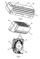
  • FIG 1 is a perspective view of an indoor unit of wall-mounted air conditioner according to an embodiment of the present invention;
  • FIG 2 is a side sectional view of an indoor unit of wall-mounted air conditioner according to an embodiment of the present invention;
  • FIG 3 is an exploded perspective view of an indoor unit of wall-mounted air conditioner according to an embodiment of the present invention;
  • FIG 4 is one perspective view of an indoor unit of wall-mounted air conditioner according to a second embodiment of the present invention;
  • FIG 5 is another perspective view of an indoor unit of wall-mounted air conditioner according to a second embodiment of the present invention;
  • FIG 6 is a side sectional view of an indoor unit of wall-mounted air conditioner according to a second embodiment of the present invention;
  • In the drawings, the reference numeral 1 denotes a housing; 2 denotes a front cover; 3 denotes a close decorative panel; 4 denotes an upper inlet port; 5 denotes a lower inlet port; 6 denotes an end portion panel; 7 denotes an arc decorative panel; 8 denotes an upper bottom surface ; 9 denotes an lower bottom surface; 10 denotes a cabinet; 11 denotes a stepped portion; 12 denotes a frame suction grill unit; 13 denotes a cross flow fan; 14 denotes an evaporator; 15 denotes an air suction duct and 16 denotes an indoor unit.
    DETAILED DESCRIPTION OF THE PREFERRED EMBODIMENTS
    A preferred embodiment of the present invention will be described hereinafter in detail with reference to the attached drawings, wherein the like reference numerals refer to the like elements throughout. The present invention may, however, be embodied in many different forms and should not be construed as being limited to the embodiment set forth herein; rather, this embodiment is provided so that the present disclosure will be thorough and complete, and will fully convey the concept of the invention to those skilled in the art.
    Embodiment 1
    Referring to FIGs 1,2 and 3, a close arc decorative panel 7 projecting outwards is fitted on the front cover 2 of an indoor unit 16 of a wall-mounted air conditioner of the present invention. The front cover 2 is provided at two sides of its upper and lower portions with end portion panels 6 projecting outwardly. A space in shape of a groove is formed by the end portion panels at the two sides and the bottom surfaces. As a result, the upper and lower air inlet port 4 and 5 are formed into openings in shape of long-strip and defined by the upper and lower edges of the close decorative panels 7, two end portion panels 6 of the front cover 2 and the upper and lower bottom surfaces 8,9. Further, a frame suction grill unit 12 is disposed at the backside of the upper inlet port 4.
    During suction operation, air can be simultaneously sucked into the indoor unit 16 through the upper and lower inlet ports 4, 5 and the frame suction grill unit 12. The air sucked through the upper and lower inlet ports 4, 5 is firstly directed into an air suction duct 15, then, guided into an evaporator 14, and discharged by an cross flow fan 13.
    Embodiment 2
    Referring to FIGs 4,5 and 6, the close decorative panel 3 of the first embodiment is replaced by a cabinet 10 in the second embodiment. The upper air inlet port 4 is opened at a top surface of the cabinet 10 and has the same construction as that of the frame suction grill unit 12. A stepped portion 11 is formed at the lower part of the cabinet 10, and a lower inlet port 5 is opened at a platform of the stepped portion 11. In this case, the lower inlet port 5 is hidden inside of the cabinet 10 without any exposure, thus a complete close panel is formed on the front side of the decorative panel 7. The upper and lower inlet ports 4,5 are disposed at the top surface and a portion of a platform of the stepped portion and an interior air suction duct 15 is formed inside the projected stepped portion 11. Further, the upper and lower inlet ports 4,5 substantially correspond to each other directly so that air flows smoothly through them, thus reducing resistance force against it and increasing the quantity of the flow air.
    During suction operation, air from the upper side is sucked in though the upper inlet port 4 and the frame suction grill unit 12, and air from the lower side is sucked in through the lower inlet port 5, then the sucked air is discharged through a evaporator 14 and an cross flow fan 13.
    In addition to the above two embodiments, the upper and lower inlet port 4,5 can also take other forms of an alternative combination. For example, the upper inlet port 4 can be disposed at a portion of the close decorative panel 3, and the lower inlet port 5 can be formed by the close decorative panel 3 and the front cover 2. It can be easily appreciated by those skilled in the art the upper inlet port 4 can be formed by the close decorative panel 3 and the front cover 2 and the lower inlet port 5 can be disposed at a portion of the close decorative panel 3.
    Although a few preferred embodiments have been shown and described, it would be appreciated by those skilled in the art that changes may be made in these embodiments without departing from the principles and spirit of the invention, the scope of the which is defined in the claims and their equivalents.
    The features disclosed in the foregoing description, in the claims and/or in the accompanying drawings may, both separately and in any combination thereof, be material for realising the invention in diverse forms thereof.

    Claims (9)

    1. An indoor unit of a wall-mounted air conditioner, comprising a housing including a front cover, characterized in that a close decorative panel instead of a suction grill unit is fitted on a front side of the front cover, and air inlet ports are disposed at upper and lower sides of the close decorative panel.
    2. An indoor unit of a wall-mounted air conditioner according to claim 1, wherein:
      the upper and lower inlet ports are defined by the front cover and the close decorative panel.
    3. An indoor unit of a wall-mounted air conditioner according to claim 1, wherein:
      the upper and lower inlet ports are opened at a portion in the upper and lower sides of the close decorative panel.
    4. An indoor unit of a wall-mounted air conditioner according to claim 1, wherein:
      the upper and lower inlet ports are defined by at least one of the arrangement that the upper and lower inlet ports are opened at a portion of the close decorative panel or the upper and lower inlet port are defined by the front cover and the close decorative panel.
    5. An indoor unit of a wall-mounted air conditioner according to claim 2, wherein:
      the front cover is provided at two sides of its upper and lower portions with end portion panels projecting outwardly;
      the close decorative panel is fitted between upper and lower end portion panels; and
      the upper and lower inlet ports defined by upper and lower edges of the close decorative panel and the end portion panels at the two sides and the upper and lower bottom surfaces of the front cover are in shape of long-strip opening.
    6. An indoor unit of a wall-mounted air conditioner according to claim 5, wherein:
      the close decorative panel is an arc panel projecting outwardly.
    7. An indoor unit of a wall-mounted air conditioner according to claim 3, wherein:
      the close decorative panel is in shape of a cabinet;
      the upper inlet port is disposed at a top surface of the cabinet; and
      a stepped portion is disposed at a lower part of the cabinet and the lower inlet port is opened at a portion of a platform of the stepped portion.
    8. An indoor unit of a wall-mounted air conditioner according to claim 7, wherein:
      the upper inlet port is one of the group consisting of an open inlet port, a frame grill inlet port and a suction grill inlet port.
    9. An indoor unit of a wall-mounted air conditioner according to claim 6 or 7, wherein:
      a frame suction grill is disposed at a backside of the upper inlet port.
    EP03024882A 2002-11-02 2003-10-31 Indoor unit of wall-mounted air conditioner Withdrawn EP1416228A3 (en)

    Applications Claiming Priority (2)

    Application Number Priority Date Filing Date Title
    CNB021357617A CN1203281C (en) 2002-11-02 2002-11-02 Indoor unit of wall hanging type air conditioner
    CN02135761 2002-11-02

    Publications (2)

    Publication Number Publication Date
    EP1416228A2 true EP1416228A2 (en) 2004-05-06
    EP1416228A3 EP1416228A3 (en) 2006-06-07

    Family

    ID=4748341

    Family Applications (1)

    Application Number Title Priority Date Filing Date
    EP03024882A Withdrawn EP1416228A3 (en) 2002-11-02 2003-10-31 Indoor unit of wall-mounted air conditioner

    Country Status (2)

    Country Link
    EP (1) EP1416228A3 (en)
    CN (1) CN1203281C (en)

    Cited By (2)

    * Cited by examiner, † Cited by third party
    Publication number Priority date Publication date Assignee Title
    US8306309B2 (en) 2007-02-09 2012-11-06 Astrium Gmbh Method and apparatus for detecting mechanical defects in a semiconductor device, particularly in a solar cell arrangement
    CN103090511A (en) * 2011-10-31 2013-05-08 珠海格力电器股份有限公司 Air port component of air pipe air conditioning unit and air pipe air conditioning unit

    Families Citing this family (3)

    * Cited by examiner, † Cited by third party
    Publication number Priority date Publication date Assignee Title
    KR101054623B1 (en) * 2005-03-09 2011-08-04 엘지전자 주식회사 Air conditioner
    CN104807079B (en) * 2014-08-29 2018-04-27 青岛海尔空调器有限总公司 A kind of wall-hanging air conditioner
    CN104214838A (en) * 2014-09-14 2014-12-17 深圳市沃森空调技术有限公司 Split wall-mounted type indoor unit

    Family Cites Families (4)

    * Cited by examiner, † Cited by third party
    Publication number Priority date Publication date Assignee Title
    JPH04143528A (en) * 1990-10-02 1992-05-18 Sanyo Electric Co Ltd Air conditioner
    JP3368717B2 (en) * 1995-04-27 2003-01-20 株式会社日立製作所 Air conditioner
    JP3168266B1 (en) * 1999-12-27 2001-05-21 株式会社日立製作所 Air conditioner
    JP2002061877A (en) * 2000-08-10 2002-02-28 Hitachi Ltd Air conditioner

    Cited By (3)

    * Cited by examiner, † Cited by third party
    Publication number Priority date Publication date Assignee Title
    US8306309B2 (en) 2007-02-09 2012-11-06 Astrium Gmbh Method and apparatus for detecting mechanical defects in a semiconductor device, particularly in a solar cell arrangement
    CN103090511A (en) * 2011-10-31 2013-05-08 珠海格力电器股份有限公司 Air port component of air pipe air conditioning unit and air pipe air conditioning unit
    CN103090511B (en) * 2011-10-31 2015-12-16 珠海格力电器股份有限公司 Air port component of air pipe air conditioning unit and air pipe air conditioning unit

    Also Published As

    Publication number Publication date
    CN1203281C (en) 2005-05-25
    CN1414306A (en) 2003-04-30
    EP1416228A3 (en) 2006-06-07

    Similar Documents

    Publication Publication Date Title
    US6557364B2 (en) Air conditioner
    JP5823881B2 (en) Air conditioner
    CN1196891C (en) Wall-mounted type microwave oven
    EP1416228A2 (en) Indoor unit of wall-mounted air conditioner
    CN103946639B (en) Flow direction changer and possess the conditioner of this flow direction changer
    JPH0599454A (en) Air conditioner
    JP7237160B2 (en) heat exchange ventilation system
    KR100814026B1 (en) Air conditioner
    CN101382317B (en) Air conditioner
    KR20230004388A (en) Indoor unit installed on the ceiling
    KR100652800B1 (en) air cleaner
    KR101105776B1 (en) Indoor unit of air conditioner
    KR101315542B1 (en) Indoor unit for air conditioner
    KR20030045442A (en) Open and close apparatus for inlet grill of air conditioner
    KR100479077B1 (en) display panel opening and closing structure of framed air conditioner
    KR100688939B1 (en) Indoor unit of ventilation
    KR101280374B1 (en) Air conditioner
    JP4049183B2 (en) Air conditioner handle structure
    KR20020086015A (en) Indoor unit of room air-conditioner
    KR100436143B1 (en) Indoor unit of air conditioner
    KR101031332B1 (en) Air conditioner
    KR20070077411A (en) Indoor unit of air conditioner
    KR100715336B1 (en) Opening and closing door structure of packaged air conditioner
    KR101090478B1 (en) Indoor unit of picture frame type air-conditioner
    KR101112993B1 (en) Panel assembly for air conditioner housing

    Legal Events

    Date Code Title Description
    PUAI Public reference made under article 153(3) epc to a published international application that has entered the european phase

    Free format text: ORIGINAL CODE: 0009012

    AK Designated contracting states

    Kind code of ref document: A2

    Designated state(s): AT BE BG CH CY CZ DE DK EE ES FI FR GB GR HU IE IT LI LU MC NL PT RO SE SI SK TR

    AX Request for extension of the european patent

    Extension state: AL LT LV MK

    PUAL Search report despatched

    Free format text: ORIGINAL CODE: 0009013

    AK Designated contracting states

    Kind code of ref document: A3

    Designated state(s): AT BE BG CH CY CZ DE DK EE ES FI FR GB GR HU IE IT LI LU MC NL PT RO SE SI SK TR

    AX Request for extension of the european patent

    Extension state: AL LT LV MK

    RIC1 Information provided on ipc code assigned before grant

    Ipc: F24F 13/20 20060101ALI20060420BHEP

    Ipc: F24F 1/00 20060101AFI20040115BHEP

    17P Request for examination filed

    Effective date: 20061113

    AKX Designation fees paid

    Designated state(s): AT BE BG CH CY CZ DE DK EE ES FI FR GB GR HU IE IT LI LU MC NL PT RO SE SI SK TR

    17Q First examination report despatched

    Effective date: 20080422

    GRAC Information related to communication of intention to grant a patent modified

    Free format text: ORIGINAL CODE: EPIDOSCIGR1

    GRAP Despatch of communication of intention to grant a patent

    Free format text: ORIGINAL CODE: EPIDOSNIGR1

    STAA Information on the status of an ep patent application or granted ep patent

    Free format text: STATUS: THE APPLICATION IS DEEMED TO BE WITHDRAWN

    18D Application deemed to be withdrawn

    Effective date: 20121122