EP1415751A2 - Dispositif d'assemblage des parties de boítier d'un appareil de soudage - Google Patents
Dispositif d'assemblage des parties de boítier d'un appareil de soudage Download PDFInfo
- Publication number
- EP1415751A2 EP1415751A2 EP03020197A EP03020197A EP1415751A2 EP 1415751 A2 EP1415751 A2 EP 1415751A2 EP 03020197 A EP03020197 A EP 03020197A EP 03020197 A EP03020197 A EP 03020197A EP 1415751 A2 EP1415751 A2 EP 1415751A2
- Authority
- EP
- European Patent Office
- Prior art keywords
- base
- snap
- ramp
- panel
- end panel
- Prior art date
- Legal status (The legal status is an assumption and is not a legal conclusion. Google has not performed a legal analysis and makes no representation as to the accuracy of the status listed.)
- Granted
Links
Images


Classifications
-
- B—PERFORMING OPERATIONS; TRANSPORTING
- B23—MACHINE TOOLS; METAL-WORKING NOT OTHERWISE PROVIDED FOR
- B23K—SOLDERING OR UNSOLDERING; WELDING; CLADDING OR PLATING BY SOLDERING OR WELDING; CUTTING BY APPLYING HEAT LOCALLY, e.g. FLAME CUTTING; WORKING BY LASER BEAM
- B23K9/00—Arc welding or cutting
- B23K9/32—Accessories
Definitions
- the present invention relates generally to a welding apparatus and, more particularly, to a system to facilitate the assembly of a welding apparatus.
- an enclosure that is generally constructed of a metal material such as aluminum and which contains and houses the various components necessary for the overall operation of the welding apparatus.
- Other structural components include a pair of end panels that are affixed to the ends of the enclosure in order to enclose the interior of the enclosure to contain those components and, therefore, there is a front panel and a rear panel, both of which are generally constructed of a molded plastic material.
- a base again generally comprised of a molded plastic material.
- the present invention is directed to an improved mounting means to facilitate the assembly of a certain structural components in the construction of a welding apparatus.
- the welding apparatus itself is comprised of a metal enclosure that houses the various components that are utilized in providing a variable power supply to carry out the welding process.
- the enclosure has a pair of end panels, that is, there is a front panel and a rear panel which are affixed to the enclosure as well as a base to contain those components therein.
- the front and rear plastic panels and base are all preferable constructed of a molded plastic material.
- a mounting system is incorporated into the front and rear panels as well as the base of the welding apparatus to facility the affixing together of the front and rear panels to the base that enables the quick and easy assembly of those components during the assembly line production of the apparatus.
- the front and rear panels are molded so as have a receptacle area located at the lower area of panels that is configured to receive an end of the base where the base is interfitted into that receptacle area and which has certain features to assure the good interfitting as well as to strengthen that affixation.
- the lateral interior surfaces of the receptacle area of the panel are contoured to closely fit around a complementary configured lateral exterior sides of the end of the base that interfits into the receptacle area.
- the fitting of the end of the base into the receptacle area therefore results in a snug fit with adjacent lateral external sides of the end of the base and the lateral internal surfaces of the receptacle area being aligned in close proximity to each other so as to add stability to the affixation of the base to a panel.
- the receptacle area of the end panel can have one or more ribs molded therein that are generally vertically oriented and which fit against and abut the upper surface of the end of the base when interfitted into the receptacle area of a panel so that the vertical movement of the base is constrained and the end of the base is automatically aligned as it is inserted into the receptacle area of a panel.
- Each end of the base has plurality of snaps, preferably U-shaped, that are molded into the plastic material of the base and which have the closed ends of the U-shaped snaps extending outwardly from each of the ends of the base to which the front and rear panels are to be affixed in assembling the welding apparatus.
- each panel there are a plurality of ramps, preferable a pair of ramps, that are in alignment with the snaps formed in the end of a base when the base and panel are being assembled together.
- Each ramp has a upwardly angled upper surface that ascends in the direction away from the base to be assembled and there is a recess that follows the uppermost end of that inclined ramp surface thereby forming a generally rear vertical wall of the ramp.
- the snaps rides upwardly along the ramps and those snaps further ride over the upper ends of the ramps such that the distal ends of the snaps lock against the vertical rear walls of the ramps, thereby locking the base and the panel together in a tool-free, easy procedure that can be readily carried out in the assembly of a welding apparatus.
- an access opening is provided in the end panel that allows access to the distal end of each of the snaps when they are in their locked position to enable a tool to be inserted into the opening to make contact with the distal ends of the snaps such that the distal ends can be raised vertically to clear the ramps and thus unlock the snaps from their locked position to an unlocked position where the base and the panel can be detached from each other.
- the locking of the base and end panel can readily be unlocked as desired to separate those components.
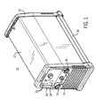
- the welding apparatus 10 comprises an enclosure 12 that is a sheet metal construction, preferable of aluminum and having a front panel 14 and a rear panel 16. Both the front and rear panels 14, 16 are preferably constructed of a molded plastic material.
- the front panel 14 has a central control section and which includes the various controls for the welding functions and can include female connectors 15 that are used to connect the welding cables.
- a control knob 18 is provided in order to control the current to the welding electrodes and a selector button 20 is provided to enable the welding apparatus to be switched between TIG and stick operation. There may also be a series of LED's 22 to provide an indication of status of the welding apparatus and to provide information as to its operation.
- a remote connector plug 24 is also used for the operation of remote controls such as a foot operated switch for the welding apparatus 10.
- a base 26 is located underneath the enclosure 12 and can also be a molded plastic construction and, a s can be seen, the base 26 can be actually e levated with respect to the floor such that the welding apparatus 10 contacts the floor through the front and rear panels 14, 16.
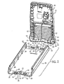
- FIG. 2 taken along with Fig. 1, there is shown an exploded view of the base 26 that is in position to be affixed by means of the present invention to the rear panel 16 for illustrative purposes, it being seen that to the front panel 14 and the rear panel 16 are both preferable affixed to the base 26 by means of the same inventive system.
- the front panel 14 and the rear panel 16 are sometimes hereinafter generically referred to as end panels.
- the base 26 has opposite ends 28, 30 that are recessed slightly downwardly and the end 28 is therefore interfitted into the rear panel 16 as will be explained.
- the base 26 also has external lateral sides 32 that are formed in the configuration of a shallow triangular shape, that is, the external lateral sides 32 are slightly angled or bowed outwardly.
- both ends 28, 30 are the same, like numbers will be used to describe the ends 28, 30.
- the ends 28, 30 have an upper surface 34 and a center portion 36 that b ows s lightly upwardly and has a boss 38 with a threaded hole 4 0 formed therein.
- a pair of snaps 42 extend outwardly from each of the ends 28, 30 and the snaps 42 are preferable molded into the molded plastic material of the base 26.
- the snaps 42 each have a distal end 44 and an elongated hole 46 formed therein.
- the snaps 42 are U-shaped in configuration and therefore the distal ends 44 are the closed ends of that U-shape configuration.
- rear panel 16 is also preferably of a molded plastic construction and includes an inner surface 48 that faces the base 16 and which encloses the components of the welding apparatus when the rear panel 16 is affixed to the enclosure 12.
- a receptacle area 50 that is formed therein and which is basically bounded by oppositely disposed internal lateral surfaces 52, 54 and a lower surface 56.
- the lower surface 56 generally follows the contour of the end 28 of the base 26 such that, when the base 26 is affixed to the rear panel 16, the end 28 of the base 26 sits atop the lower surface 56 in close proximity therewith.
- a rea 50 is also formed in the lower surface 56 of the receptacle a rea 50 through which a screw can be inserted and threaded into the threaded hole 40 to finalize the affixing of the rear panel 16 to the base 26.
- ribs 64 and 66 extending outwardly from the inner surface 48 of the rear panel 16 and having lower edges 68, 70 respectively, that are spaced a predetermined distance above the lower surface 56 of the receptacle area 50 thereby leaving an opening between the lower edges 68, 70 and the lower surface 56. Therefore, that predetermined distance is dimensioned such that the lower edges 68, 70 of the ribs 64, 66 abut against the upper surface 34 of the end 28 when the end 28 is interfitted into the receptacle area 50 in joining the base 26 to the rear panel 16. That abutting relationship stabilizes the base 26 to the rear panel 16 by constraining the vertical movement between the base 26 and the rear panel 16 as well as aligns the base 26 with respect to the rear panel 16 in order to also align the snaps 42 with the ramps 60.
- Fig 3 there is shown a perspective view wherein the base 26 has been affixed to the rear panel 16, thereby forming a subassembly for the later further assembly of the welding apparatus 10 (Fig. 1).
- Fig 3 it can be seen that that the lateral internal surfaces 52, 54 within the receptacle area 50 closely surround the lateral external sides 32 of the base 26 in close proximity thereto such that the end 28 of the base 26 is nested within the receptacle area 50 and that the base 26 is supported against side to side motion while, at the same time, rib 66 rests against the upper surface 34 of the end 28 to resist vertical movement between the base 26 and the rear panel 16 and further to guide the snaps 42 into their position atop of the ramps 60.
- the ramps 60 extend upwardly through elongated holes 46 in the snaps 42 to hold the base 26 in its position firmly to the rear panel 16.
- the snaps 42 basically encircle the ramps 60 and the distal end 44 of the snaps 42 are positioned in a locked position behind the snaps 42 to prevent the base 26 from becoming detached from the rear panel 16.
- the ramps 60 have an upwardly inclined top surface 68 and a vertical rear wall 70 and the distal end 44 of the snaps 42 b ecomes locked in position b ehind the vertical rear w all 70 to retain the base 26 in the locked position to the rear panel 16.
- the end 28 is inserted into the receptacle area 50 such that the snaps 42 slide up along the inclined top surface 68 of the ramps 60 and eventually pass beyond the inclined top surface 68 and drop down into the recesses 62 to become locked in position against the vertical rear wall 70 of the ramps 60.
- Fig. 5 taken along with Fig 4, there is shown a cross sectional view of a ramp 60 taken along the line 5-5 of Fig. 4.
- the inclined top surface 68 slopes upwardly in the direction away from the base 26 and terminates at the vertical rear wall 70 where the distal end 44 of the snap 42 becomes held in the locked position within the recess 62.
- the access opening 72 By means of the access opening 72, a tool can be inserted through the access opening 72 to contact and push the distal end 44 of the snap 42 upwardly to the point it can clear the vertical rear wall 70 of the ramp so that the snap 42 can be unlocked and the base 26 detached from the rear panel 16.
- the locking system of the invention can be unlocked through the access opening 72 to disassemble the base 26 from the rear panel 16.
Landscapes
- Engineering & Computer Science (AREA)
- Physics & Mathematics (AREA)
- Plasma & Fusion (AREA)
- Mechanical Engineering (AREA)
- Lining Or Joining Of Plastics Or The Like (AREA)
Applications Claiming Priority (2)
| Application Number | Priority Date | Filing Date | Title |
|---|---|---|---|
| US65571 | 2002-10-31 | ||
| US10/065,571 US7375305B2 (en) | 2002-10-31 | 2002-10-31 | System for assembling welding apparatus |
Publications (3)
| Publication Number | Publication Date |
|---|---|
| EP1415751A2 true EP1415751A2 (fr) | 2004-05-06 |
| EP1415751A3 EP1415751A3 (fr) | 2005-01-19 |
| EP1415751B1 EP1415751B1 (fr) | 2010-03-31 |
Family
ID=32092206
Family Applications (1)
| Application Number | Title | Priority Date | Filing Date |
|---|---|---|---|
| EP03020197A Expired - Lifetime EP1415751B1 (fr) | 2002-10-31 | 2003-09-05 | Appareil de soudage avec des joints encliquants pour des parties de boîtier |
Country Status (3)
| Country | Link |
|---|---|
| US (2) | US7375305B2 (fr) |
| EP (1) | EP1415751B1 (fr) |
| DE (1) | DE60331885D1 (fr) |
Cited By (1)
| Publication number | Priority date | Publication date | Assignee | Title |
|---|---|---|---|---|
| EP2253409A1 (fr) * | 2009-05-19 | 2010-11-24 | Luigi Marin Celestino | Kit d'accessoires pour moteurs d'entraînement du fil de contrôle et potentiomètres de chalumeaux de soudage au plasma, par protection gazeuse inerte, protection gazeuse active et TIG |
Families Citing this family (4)
| Publication number | Priority date | Publication date | Assignee | Title |
|---|---|---|---|---|
| US9700965B2 (en) * | 2013-03-15 | 2017-07-11 | Illinois Tool Works Inc. | Base for welding type power supply |
| EP3017902B1 (fr) * | 2014-11-07 | 2017-03-29 | The Esab Group, Inc. | Carter renforcé pour un système de soudage portable |
| USD812119S1 (en) * | 2016-07-14 | 2018-03-06 | Esab Ab | Portable welding power source with cooling module |
| USD811456S1 (en) * | 2016-07-14 | 2018-02-27 | Esab Ab | Portable welding power source |
Family Cites Families (8)
| Publication number | Priority date | Publication date | Assignee | Title |
|---|---|---|---|---|
| US4166195A (en) * | 1977-07-22 | 1979-08-28 | Isotrol Systems | Duct apparatus for distribution of isolated power and equipotential ground |
| US4368563A (en) * | 1981-07-13 | 1983-01-18 | Allied Corporation | Seat belt buckle with plastic cover |
| US4451693A (en) * | 1982-03-22 | 1984-05-29 | Vest Gary W | Combined ballast container and wall plug for portable electrical equipment |
| US4903377A (en) * | 1988-05-31 | 1990-02-27 | Gateway Industries, Inc. | Free-falling, self-locking adjustable tip assembly |
| TW283274B (fr) * | 1994-11-08 | 1996-08-11 | Sansha Denki Seisakusho Co Ltd | |
| US5700165A (en) * | 1995-12-11 | 1997-12-23 | General Motors Corporation | Fused high ampacity electrical quick disconnect |
| US5795193A (en) * | 1996-10-23 | 1998-08-18 | Yazaki Corporation | Power distribution box with busbar having bolt retaining means |
| US6489591B1 (en) * | 2000-04-10 | 2002-12-03 | Illinois Tool Works Inc. | Cooling air circuits for welding machine |
-
2002
- 2002-10-31 US US10/065,571 patent/US7375305B2/en not_active Expired - Fee Related
-
2003
- 2003-09-05 DE DE60331885T patent/DE60331885D1/de not_active Expired - Lifetime
- 2003-09-05 EP EP03020197A patent/EP1415751B1/fr not_active Expired - Lifetime
-
2008
- 2008-03-14 US US12/048,903 patent/US8558138B2/en not_active Expired - Lifetime
Cited By (1)
| Publication number | Priority date | Publication date | Assignee | Title |
|---|---|---|---|---|
| EP2253409A1 (fr) * | 2009-05-19 | 2010-11-24 | Luigi Marin Celestino | Kit d'accessoires pour moteurs d'entraînement du fil de contrôle et potentiomètres de chalumeaux de soudage au plasma, par protection gazeuse inerte, protection gazeuse active et TIG |
Also Published As
| Publication number | Publication date |
|---|---|
| US20040084428A1 (en) | 2004-05-06 |
| US8558138B2 (en) | 2013-10-15 |
| EP1415751B1 (fr) | 2010-03-31 |
| US20080156787A1 (en) | 2008-07-03 |
| DE60331885D1 (de) | 2010-05-12 |
| EP1415751A3 (fr) | 2005-01-19 |
| US7375305B2 (en) | 2008-05-20 |
Similar Documents
| Publication | Publication Date | Title |
|---|---|---|
| US8558138B2 (en) | System for assembling welding apparatus | |
| US6940015B2 (en) | Power outlet strip having changeable cover | |
| US5429235A (en) | Tool box assembly | |
| US5493475A (en) | Cooling device for an integrated circuit | |
| US5691878A (en) | Snap-lockable housing for fluorescent lamp ballasts | |
| US20040237426A1 (en) | Mat ramp securement and method | |
| JP3181020B2 (ja) | 低挿入力コネクタ | |
| EP0765971A1 (fr) | Robinet | |
| EP0843384A3 (fr) | Un connecteur modulaire | |
| US5702021A (en) | Locking construction of electric connection box | |
| US5971507A (en) | Relay rack enclosure | |
| JP3002098B2 (ja) | コネクタの組立方法およびコネクタハウジング | |
| US6706987B1 (en) | Rotary push switch | |
| GB2381582A (en) | Level having a detachable securing structure | |
| US4823971A (en) | Housing assembly for a smoke exhaust electrical fan | |
| US6203351B1 (en) | Connector locking structure | |
| JP2509754Y2 (ja) | コネクタ | |
| JPH06275336A (ja) | コネクタ | |
| CN222955109U (zh) | 用于家用电器的固定件、定位件和家用电器 | |
| JPH11307164A (ja) | リテーナ付きコネクタ | |
| JPH09190808A (ja) | 電池ケース | |
| EP4554344A1 (fr) | Dispositif de montage de module d'interface humaine | |
| US20060099844A1 (en) | Plate locking systems for mated electrical connectors and methods thereof | |
| JPH0521783Y2 (fr) | ||
| JPH0648702Y2 (ja) | 押ボタンスイッチ |
Legal Events
| Date | Code | Title | Description |
|---|---|---|---|
| PUAI | Public reference made under article 153(3) epc to a published international application that has entered the european phase |
Free format text: ORIGINAL CODE: 0009012 |
|
| AK | Designated contracting states |
Kind code of ref document: A2 Designated state(s): AT BE BG CH CY CZ DE DK EE ES FI FR GB GR HU IE IT LI LU MC NL PT RO SE SI SK TR |
|
| AX | Request for extension of the european patent |
Extension state: AL LT LV MK |
|
| PUAL | Search report despatched |
Free format text: ORIGINAL CODE: 0009013 |
|
| AK | Designated contracting states |
Kind code of ref document: A3 Designated state(s): AT BE BG CH CY CZ DE DK EE ES FI FR GB GR HU IE IT LI LU MC NL PT RO SE SI SK TR |
|
| AX | Request for extension of the european patent |
Extension state: AL LT LV MK |
|
| RIC1 | Information provided on ipc code assigned before grant |
Ipc: 7H 01F 27/02 B Ipc: 7B 23K 9/10 B Ipc: 7B 23K 9/32 A |
|
| 17P | Request for examination filed |
Effective date: 20050520 |
|
| AKX | Designation fees paid |
Designated state(s): DE FR IT |
|
| APBN | Date of receipt of notice of appeal recorded |
Free format text: ORIGINAL CODE: EPIDOSNNOA2E |
|
| APBR | Date of receipt of statement of grounds of appeal recorded |
Free format text: ORIGINAL CODE: EPIDOSNNOA3E |
|
| APAF | Appeal reference modified |
Free format text: ORIGINAL CODE: EPIDOSCREFNE |
|
| APBT | Appeal procedure closed |
Free format text: ORIGINAL CODE: EPIDOSNNOA9E |
|
| RTI1 | Title (correction) |
Free format text: WELDING APPARATUS WITH SNAP LOCK MECHANISM FOR HOUSING PARTS. |
|
| GRAP | Despatch of communication of intention to grant a patent |
Free format text: ORIGINAL CODE: EPIDOSNIGR1 |
|
| GRAS | Grant fee paid |
Free format text: ORIGINAL CODE: EPIDOSNIGR3 |
|
| GRAA | (expected) grant |
Free format text: ORIGINAL CODE: 0009210 |
|
| AK | Designated contracting states |
Kind code of ref document: B1 Designated state(s): DE FR IT |
|
| REF | Corresponds to: |
Ref document number: 60331885 Country of ref document: DE Date of ref document: 20100512 Kind code of ref document: P |
|
| PLBE | No opposition filed within time limit |
Free format text: ORIGINAL CODE: 0009261 |
|
| STAA | Information on the status of an ep patent application or granted ep patent |
Free format text: STATUS: NO OPPOSITION FILED WITHIN TIME LIMIT |
|
| 26N | No opposition filed |
Effective date: 20110104 |
|
| PGFP | Annual fee paid to national office [announced via postgrant information from national office to epo] |
Ref country code: IT Payment date: 20120924 Year of fee payment: 10 Ref country code: FR Payment date: 20121001 Year of fee payment: 10 |
|
| PGFP | Annual fee paid to national office [announced via postgrant information from national office to epo] |
Ref country code: DE Payment date: 20120927 Year of fee payment: 10 |
|
| REG | Reference to a national code |
Ref country code: DE Ref legal event code: R119 Ref document number: 60331885 Country of ref document: DE Effective date: 20140401 |
|
| REG | Reference to a national code |
Ref country code: FR Ref legal event code: ST Effective date: 20140530 |
|
| PG25 | Lapsed in a contracting state [announced via postgrant information from national office to epo] |
Ref country code: DE Free format text: LAPSE BECAUSE OF NON-PAYMENT OF DUE FEES Effective date: 20140401 Ref country code: IT Free format text: LAPSE BECAUSE OF NON-PAYMENT OF DUE FEES Effective date: 20130905 Ref country code: FR Free format text: LAPSE BECAUSE OF NON-PAYMENT OF DUE FEES Effective date: 20130930 |
|
| P01 | Opt-out of the competence of the unified patent court (upc) registered |
Effective date: 20230523 |