EP1415747A2 - Multi-station electrical discharge machining with manufacturing interrupt reduction - Google Patents
Multi-station electrical discharge machining with manufacturing interrupt reduction Download PDFInfo
- Publication number
- EP1415747A2 EP1415747A2 EP03256864A EP03256864A EP1415747A2 EP 1415747 A2 EP1415747 A2 EP 1415747A2 EP 03256864 A EP03256864 A EP 03256864A EP 03256864 A EP03256864 A EP 03256864A EP 1415747 A2 EP1415747 A2 EP 1415747A2
- Authority
- EP
- European Patent Office
- Prior art keywords
- servomotor
- work station
- electrical discharge
- discharge machining
- workpiece
- Prior art date
- Legal status (The legal status is an assumption and is not a legal conclusion. Google has not performed a legal analysis and makes no representation as to the accuracy of the status listed.)
- Granted
Links
Images

Classifications
-
- B—PERFORMING OPERATIONS; TRANSPORTING
- B23—MACHINE TOOLS; METAL-WORKING NOT OTHERWISE PROVIDED FOR
- B23H—WORKING OF METAL BY THE ACTION OF A HIGH CONCENTRATION OF ELECTRIC CURRENT ON A WORKPIECE USING AN ELECTRODE WHICH TAKES THE PLACE OF A TOOL; SUCH WORKING COMBINED WITH OTHER FORMS OF WORKING OF METAL
- B23H9/00—Machining specially adapted for treating particular metal objects or for obtaining special effects or results on metal objects
- B23H9/14—Making holes
-
- B—PERFORMING OPERATIONS; TRANSPORTING
- B23—MACHINE TOOLS; METAL-WORKING NOT OTHERWISE PROVIDED FOR
- B23H—WORKING OF METAL BY THE ACTION OF A HIGH CONCENTRATION OF ELECTRIC CURRENT ON A WORKPIECE USING AN ELECTRODE WHICH TAKES THE PLACE OF A TOOL; SUCH WORKING COMBINED WITH OTHER FORMS OF WORKING OF METAL
- B23H1/00—Electrical discharge machining, i.e. removing metal with a series of rapidly recurring electrical discharges between an electrode and a workpiece in the presence of a fluid dielectric
-
- B—PERFORMING OPERATIONS; TRANSPORTING
- B23—MACHINE TOOLS; METAL-WORKING NOT OTHERWISE PROVIDED FOR
- B23H—WORKING OF METAL BY THE ACTION OF A HIGH CONCENTRATION OF ELECTRIC CURRENT ON A WORKPIECE USING AN ELECTRODE WHICH TAKES THE PLACE OF A TOOL; SUCH WORKING COMBINED WITH OTHER FORMS OF WORKING OF METAL
- B23H1/00—Electrical discharge machining, i.e. removing metal with a series of rapidly recurring electrical discharges between an electrode and a workpiece in the presence of a fluid dielectric
- B23H1/02—Electric circuits specially adapted therefor, e.g. power supply, control, preventing short circuits or other abnormal discharges
- B23H1/028—Electric circuits specially adapted therefor, e.g. power supply, control, preventing short circuits or other abnormal discharges for multiple gap machining
-
- B—PERFORMING OPERATIONS; TRANSPORTING
- B23—MACHINE TOOLS; METAL-WORKING NOT OTHERWISE PROVIDED FOR
- B23H—WORKING OF METAL BY THE ACTION OF A HIGH CONCENTRATION OF ELECTRIC CURRENT ON A WORKPIECE USING AN ELECTRODE WHICH TAKES THE PLACE OF A TOOL; SUCH WORKING COMBINED WITH OTHER FORMS OF WORKING OF METAL
- B23H9/00—Machining specially adapted for treating particular metal objects or for obtaining special effects or results on metal objects
- B23H9/10—Working turbine blades or nozzles
-
- Y—GENERAL TAGGING OF NEW TECHNOLOGICAL DEVELOPMENTS; GENERAL TAGGING OF CROSS-SECTIONAL TECHNOLOGIES SPANNING OVER SEVERAL SECTIONS OF THE IPC; TECHNICAL SUBJECTS COVERED BY FORMER USPC CROSS-REFERENCE ART COLLECTIONS [XRACs] AND DIGESTS
- Y10—TECHNICAL SUBJECTS COVERED BY FORMER USPC
- Y10T—TECHNICAL SUBJECTS COVERED BY FORMER US CLASSIFICATION
- Y10T408/00—Cutting by use of rotating axially moving tool
- Y10T408/36—Machine including plural tools
- Y10T408/38—Plural, simultaneously operational tools
- Y10T408/3806—Plural, simultaneously operational tools with plural simultaneously operational work stations
Definitions
- This invention relates generally to electrical discharge machining and more particularly to electrical discharge machining workpieces, such as aircraft engine parts, which have several features machined therein.
- EDM Electrical discharge machining
- Conventional EDM apparatuses typically employ an electrode having the desired shape that is advanced toward the workpiece.
- a suitable power supply is applied to create an electrical potential between the workpiece and electrode for forming a controlled spark which melts and vaporizes the workpiece material to form the desired feature.
- the cutting pattern of the electrode is usually computer numerically controlled whereby servomotors control the relative positions of the electrode and workpiece.
- the electrode and workpiece are immersed in a dielectric fluid, which provides insulation against premature spark discharge, cools the machined area, and flushes away the removed material.
- One drawback to electrical discharge machining is that it is a relatively slow process, especially when several distinct features need to be machined into a workpiece. This is particularly so in the aircraft engine industry where electrical discharge machining is widely used for machining various features into aircraft engine parts.
- an EDM apparatus that machines a number of parts at one time.
- Such an apparatus has a plurality of work stations, each of which has a workpiece fixture located in a single dielectric tank. The work stations are all typically connected to a common power supply.
- machining takes place in series one part at a time. That is, a spark will be created in the first work station and then the next work station and so on until each station has a spark supplied. This sequence is repeated until the machining operation is completed for each workpiece.
- throughput can be improved with this type of apparatus, machining multiple features into a single workpiece is still a relatively slow process.
- an EDM apparatus that employs multiple electrodes in each work station.
- Such an EDM apparatus is capable of performing multiple machining operations on a workpiece simultaneously.
- a separate servomotor, power supply and computer numerical control (CNC) is provided for each electrode.
- the large number of servomotors, power supplies and CNCs increases the complexity and cost of the manufacturing system and requires a lot of floor space in the machining shop.
- the total number of power supplies and CNCs can be reduced by using a power transfer switch that selectively delivers power to one work station at a time. While reducing the number of power supplies and CNCs, this configuration still utilizes a large number of servomotors.
- Such EDM apparatuses can be susceptible to manufacturing interrupts.
- the above-mentioned need is met by the present invention which provides an electrical discharge machining apparatus including at least two work stations.
- a first servomotor is mounted above the first and second work stations, and a second servomotor mounted to the first servomotor so as to be selectively positioned over either of the first or second work stations by the first servomotor.
- the second servomotor is capable of causing relative motion between an electrode and a workpiece fixture in the first work station when positioned over the first work station and causing relative motion between an electrode and a workpiece fixture in the second work station when positioned over the second work station.
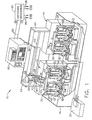
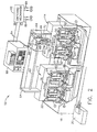
- FIGS. 1 and 2 show an electrical discharge machining (EDM) apparatus 10.
- the EDM apparatus 10 includes first and second work stations 12 and 14 disposed side-by-side in a tank 16, which is shown in partial cut-away to reveal the work stations 12, 14 therein. Although two work stations are shown for purposes of illustration, it should be noted that virtually any number of such stations could be employed in the EDM apparatus 10 of the present invention.
- the tank 16 is filled with a suitable dielectric fluid, such as a dielectric oil, so that the workpieces are immersed in the fluid.
- the dielectric fluid insulates against premature spark discharge, cools the machined area, and flushes away machining debris.
- a float switch (not shown) is provided in the tank 16 for detecting when the dielectric fluid reaches a sufficient depth.
- the float switch is located such that the level of dielectric fluid is just high enough to immerse workpieces installed in the work stations 12, 14.
- a conventional filtering system 20 is connected to the tank 16 for filtering the dielectric fluid, preferably down to one micron absolute.
- Each work station 12, 14 operates independently to machine separate sets of workpieces. More specifically, the first work station 12 includes first and second machining heads 22 and 24, and the second work station 14 includes third and fourth machining heads 26 and 28. As described in more detail below, each machining head machines two workpieces at a time such that each work station can machine four workpieces at a time. It should be noted that two workpieces per machining head and two machining heads per work station are shown for purposes of illustration only. The present invention is not limited to this particular arrangement. Virtually any combination of workpieces per machining head and machining heads per work station is possible, although it is desirable that the number of workpieces machined by a work station during a single operation be divisible the number of parts in a complete set so that extra parts are not produced.
- the first machining head 22 includes a base 30, a lower support block 32 and an upper support block 34.
- the lower and upper support blocks 32, 34 are supported on the base 30 by a pair of insulated mounting posts 36, with the upper support block 34 being positioned directly above the lower support block 32.
- First and second workpiece fixtures 38 and 40 are mounted side-by-side on the front surface of the lower support block 32.
- the first workpiece fixture 38 includes a part holder 42 fixedly attached to the lower support block 32.
- the part holder 42 is configured to receive a workpiece 44 therein.
- a spring-biased loading clamp 46 is pivotally connected to the part holder 42 for retaining the workpiece 44 in the part holder 42.
- the loading clamp 46 is pivotable between a closed position engaging the workpiece 44 and an open position not engaging the workpiece 44. When the loading clamp 46 is in its closed position, the workpiece 44 is pressed against the part holder 42 by the spring force and thus held in position. The workpiece 44 can be removed from the part holder 42 when the loading clamp 46 is in its open position.
- the part holder 42 is limited to one specific workpiece configuration (thereby preventing loading of a wrong workpiece), but the removable mounting of the part holder 42 to the lower support block 32 means it can be readily exchanged with another part holder that accepts a different workpiece configuration.
- the second workpiece fixture 40 is substantially similar to the first workpiece fixture 38; consequently, a detailed description of the second workpiece fixture 40 will not be repeated here.
- the part holders of the first and second workpiece fixtures 38, 40 do not necessarily have to have the exact same configuration. That is, the two workpiece fixtures can be designed to retain workpieces of different sizes and/or shapes.
- the first machining head 22 further includes a slider 47 moveably mounted to the front surface of the upper support block 34. Specifically, the slider 47 is arranged to slide relative to the upper support block 34 in a vertical direction.
- a carriage 48 is fixedly mounted to the slider 47 for movement therewith.
- the carriage 48 is a substantially rectangular plate made of an electrically conductive material.
- An arch 49 having an upwardly extending tab 50 is formed on the upper end of the slider 47.
- An exchangeable electrode holder 52 is removably mounted to the lower end of the carriage 48.
- the electrode holder 52 has a pair of electrode receiving slots formed therein. The slots are positioned side-by-side so as to be located directly above a corresponding one of the first and second workpiece fixtures 38 and 40.
- An electrode 54 is disposed in each slot and secured by respective lock screws 56.
- the electrodes 54 can be any type of electrode used in electrical discharge machining.
- the electrode holder 52 can be removed and exchanged with another electrode holder. This provides a simple means of changing electrodes so that the work station can be used for a different machining operation that calls for different electrodes.
- Back-and-forth vertical motion of the slider 47 causes the carriage 48, the electrode holder 52 and the electrodes 54 to move in and out of machining engagement with the respective workpieces 44.
- the workpiece fixtures could be mounted on the carriages and the electrode holders mounted on the fixed base.
- the three other machining heads are substantially similar to the above-described first machining head 22. Thus, a detailed description of the other machining heads will not be repeated here. However, it should be noted that while they function in the same manner, all of the machining heads are not necessarily identical. That is, the electrodes of the first and second machining heads 22, 24 could differ in shape, size, material and/or polarity from the electrodes of the third and fourth machining heads 26, 28. Thus, the first and second work stations 12, 14 can machine different features. The first and second work stations 12, 14 can also operate with different EDM parameters (e.g., power and time).
- EDM parameters e.g., power and time
- the EDM apparatus 10 includes a horizontally-oriented linear servomotor 58 and a vertically-oriented linear servomotor 60.
- linear servomotors are shown to facilitate disclosure of the present invention, rotary servomotors could alternatively be used. However, linear servomotors are generally preferred because of their better speed, faster frequency response and positional accuracy.
- the horizontal servomotor 58 includes a linear motor stator rod 62 supported above the first and second work stations 12, 14 by a frame 64.
- the stator rod 62 is oriented horizontally and spans both work stations 12, 14.
- a linear motor slider 66 is slidingly mounted on the stator rod 62.
- the vertical servomotor 60 includes a linear motor stator rod 68 mounted in a yoke 70 that is attached to the horizontal slider 66 for movement therewith.
- the yoke 70 is oriented so that the stator rod 68 extends vertically, perpendicular to the horizontal stator rod 62.
- a linear motor slider 72 is slidingly mounted on the vertical stator rod 68.
- An actuator bar 74 is attached to the front surface of the vertical slider 72 and extends downward therefrom.
- the horizontal servomotor 58 When the horizontal servomotor 58 is energized, the horizontal slider 66 is caused to move linearly with respect to the horizontal stator rod 62.
- the vertical servomotor 60 moves laterally with the horizontal slider 66.
- the vertical servomotor 60 can be positioned directly over the first work station 12 as shown in Figure 1 or directly over the second work station 14 as shown in Figure 2.
- the first work station 12 has a first contact block 76 that extends between and is attached to the slider tabs 50 of the first and second machining heads 22 and 24.
- the second work station 14 has a second contact block 78 that extends between and is attached to the slider tabs 50 of the third and fourth machining heads 26 and 28.
- the vertical slider 72 When the vertical servomotor 60 is energized while positioned directly over the first work station 12 as shown in Figure 1, the vertical slider 72 is caused to move linearly with respect to the vertical stator rod 68. Downward movement of the vertical slider 72 causes the actuator bar 74 to move into engagement with the first contact block 76. Further downward movement of the vertical slider 72 is transmitted by the actuator bar 74, the first contact block 76 and the respective sliders 47 so as to cause the carriages 48 of both the first and second machining heads 22, 24 move downward. This in turn causes the electrodes 54 to move into machining engagement with the corresponding workpiece 44.
- the sliders 47 are normally biased upward by a compression spring (not shown) disposed in each arch 49.
- the compression springs When the vertical servomotor 60 is energized to move the vertical slider 72 (and actuator bar 74) upward, the compression springs cause the sliders 47 and the first contact bar 76 to move upward, thereby retracting the carriage 48, electrode holder 52 and electrodes 54.
- the compression spring forces are balanced to the weight of the entire slider mechanism so that the vertical servomotor 60 is very lightly loaded.
- the vertical slider 72 When the vertical servomotor 60 is energized while positioned directly over the second work station 14 as shown in Figure 2, the vertical slider 72 is caused to move linearly with respect to the vertical stator rod 68. Downward movement of the vertical slider 72 causes the actuator bar 74 to move into engagement with the second contact block 78. Further downward movement of the vertical slider 72 is transmitted by the actuator bar 74, the second contact block 78 and the respective sliders 47 so as to cause the carriages 48 of both the third and fourth machining heads 26, 28 move downward. This in turn causes the electrodes 54 to move into machining engagement with the corresponding workpiece 44. Upward movement of the vertical slider 72 permits compression springs in the arches 49 to force the sliders 47 upward, thereby retracting the electrodes 54.
- the EDM apparatus 10 also includes a standard EDM control system 80.
- the EDM control system 80 includes a power supply or spark generator and a controller, such as a computer numerical control (CNC).
- the power supply selectively provides energy to one of the first and second work stations 12, 14 via a switching mechanism 82 that is connected to the EDM control system 80 by a set of input power cables 84.
- the switching mechanism 82 (shown schematically in Figures 1 and 2) is a simple electro-mechanical mechanism that is capable of switching power between the first and second work stations 12, 14.
- the switching mechanism 82 When the switching mechanism 82 is in a first state, power from the EDM control system 80 is delivered to the first work station 12 via a first set of output power cables 86, and when the switching mechanism 82 is in a second state, power from the EDM control system 80 is delivered to the second work station 14 via a second set of output power cables 88.
- the first and second sets of output power cables 86, 88 are connected to the part holders 42 and the carriages 48 of the first and second work stations 12, 14, respectively.
- electrical energy is delivered to the workpieces 44 of the selected work station through the electrically conductive part holders 42 and to the electrodes 54 of the selected work station through the electrically conductive carriages 48 and electrode holders 52.
- the controller of the EDM control system 80 is connected to the vertical servomotor 60 via servo cables 90, which travel with the vertical servomotor 60.
- the first work station 12 alternates with the second work station 14 depending on the state of the switching mechanism 82. While one of the work stations is operating, the other work station is being prepared for the next operation. For example, with new workpieces 44 loaded in the workpiece fixtures 38, 40 of the first and second machining heads 22, 24, the horizontal servomotor 58 is operated to position the vertical servomotor 60 over the first work station 12, as shown in Figure 1. The switching mechanism 82 is placed in its first state so that EDM power is supplied to the first work station 12.
- the vertical servomotor 60 is energized so that the electrodes 54 are advanced under the control of the EDM control system 80 toward the corresponding workpieces 44 via coordinated downward motion of the vertical slider 72, the actuator bar 74, the first contact block 76, the respective sliders 47 and the respective carriages 48.
- the electrodes 54 and workpieces 44 are energized by the power supply in the EDM control system 80 for providing electrical energy to produce electrical discharges or sparks between the electrodes 54 and the workpieces 44 when the electrodes 54 are positioned adjacent to the corresponding workpiece 44.
- the vertical servomotor 60 continues to advance the electrodes 54 as dictated by the EDM control system 80 until machining of the desired features is finished.
- the vertical servomotor 60 retracts the actuator bar 74, allowing the electrodes 54 to retract.
- the horizontal servomotor 58 is operated to position the vertical servomotor 60 over the second work station 14, as shown in Figure 2.
- the switching mechanism 82 is switched to its second state so that EDM power is supplied to the second work station 14.
- the vertical servomotor 60 is energized so that the electrodes 54 are advanced under the control of the EDM control system 80 toward the corresponding workpieces 44 via coordinated downward motion of the vertical slider 72, the actuator bar 74, the second contact block 78, the respective sliders 47 and the respective carriages 48.
- the electrodes 54 and workpieces 44 are energized by the power supply in the EDM control system 80 for providing electrical energy to produce electrical discharges or sparks between the electrodes 54 and the workpieces 44 when the electrodes 54 are positioned adjacent to the corresponding workpiece 44.
- the vertical servomotor 60 continues to advance the electrodes 54 as dictated by the EDM control system 80 until machining of the desired features is finished. While the second work station 14 is operating, the first work station 12 is being prepared for the next operation. This alternating work cycle repeats continuously.
- the work stations 12, 14 operate independently because only one of the work stations is connected to the EDM control system 80 at a time.
- the work stations 12, 14 can perform different operations; that is, each station can work on a different type of part and/or machine a different feature.
- the work stations can have different types of electrodes (e.g., one station can have a graphite electrode, while other station may use brass, copper or copper tungsten electrodes) and use different electrode polarities.
- the first work station 12 has graphite electrodes with negative polarity that are sized to machine wide slots in the workpieces.
- the second work station has copper tungsten electrodes with positive polarity.
- the electrodes in the third machining head 26 are sized to machine notches, and the electrodes in the fourth machining head 28 are sized to machine holes.
Landscapes
- Engineering & Computer Science (AREA)
- Mechanical Engineering (AREA)
- Physics & Mathematics (AREA)
- Thermal Sciences (AREA)
- Electrical Discharge Machining, Electrochemical Machining, And Combined Machining (AREA)
Abstract
Description
- 2. The electrical discharge machining apparatus (10) of clause 1 wherein said first servomotor (58) is a linear servomotor having a first stator bar (62) supported above said first and second work stations (12,14) and a first slider (66) mounted on said first stator bar (62).
- 3. The electrical discharge machining apparatus (10) of clause 2 wherein said second servomotor (60) is a linear servomotor having a second stator bar (68) mounted to said first slider (66) and a second slider (72) mounted on said second stator bar (68).
- 4. The electrical discharge machining apparatus (10) of clause 3 wherein said first and second stator bars (62,68) are disposed perpendicularly to one another.
- 5. The electrical discharge machining apparatus (10) of clause 1 wherein said first and second work stations (12,14) each comprise a plurality of machining heads (22,24,26,28), each machining head (22,24,26,28) including a base (30), an electrode holder (52) mounted to said base (30), and a workpiece fixture (38) mounted to said base (30), at least one of said electrode holder (52) and said workpiece fixture (38) being movable relative to said base (30) so as to permit relative motion therebetween.
- 6. The electrical discharge machining apparatus (10) of clause 5 wherein said second servomotor (60) causes relative motion between corresponding electrode holders (52) and workpiece fixtures (38) in said first work station (12) when positioned over said first work station (12) and said second servomotor (60) causes relative motion between corresponding electrode holders (52) and workpiece fixtures (38) in said second work station (14) when positioned over said second work station (14).
- 7. The electrical discharge machining apparatus (10) of clause 1 further comprising a power supply and a switching mechanism (82) having a first state in which said power supply is connected to said first work station (12) and a second state in which said power supply is connected to said second work station (14).
- 8. An electrical discharge machining apparatus (10) comprising:
- a first work station (12) having a first electrode (54) and a first workpiece fixture (38);
- a second work station (14) having a second electrode (54) and a second workpiece fixture (40);
- a first servomotor (58) mounted above said first and second work stations (12,14); and
- a second servomotor (60) mounted to said first servomotor (58) so as to be selectively positioned over either of said first and second work stations (12,14) by said first servomotor (58), said second servomotor (60) being capable of causing relative motion between said first electrode (54) and said first workpiece fixture (38) when positioned over said first work station (12) and causing relative motion between said second electrode (54) and said second workpiece fixture (40) when positioned over said second work station (14).
Claims (10)
- An electrical discharge machining apparatus (10) comprising:first and second work stations (12,14);a first servomotor (58) mounted above said first and second work stations (12,14); anda second servomotor (60) mounted to said first servomotor (58) so as to be selectively positioned over either of said first and second work stations (12,14) by said first servomotor (58).
- The electrical discharge machining apparatus (10) of claim 1 wherein said first servomotor (58) is a linear servomotor having a first stator bar (62) supported above said first and second work stations (12,14) and a first slider (66) mounted on said first stator bar (62).
- The electrical discharge machining apparatus (10) of claim 2 wherein said second servomotor (60) is a linear servomotor having a second stator bar (68) mounted to said first slider (66) and a second slider (72) mounted on said second stator bar (68).
- The electrical discharge machining apparatus (10) of claim 1 wherein said first and second work stations (12,14) each comprise a plurality of machining heads (22,24,26,28), each machining head (22,24,26,28) including a base (30), an electrode holder (52) mounted to said base (30), and a workpiece fixture (38) mounted to said base (30), at least one of said electrode holder (52) and said workpiece fixture (38) being movable relative to said base (30) so as to permit relative motion therebetween.
- The electrical discharge machining apparatus (10) of claim 4 wherein said second servomotor (60) causes relative motion between corresponding electrode holders (52) and workpiece fixtures (38) in said first work station (12) when positioned over said first work station (12) and said second servomotor (60) causes relative motion between corresponding electrode holders (52) and workpiece fixtures (38) in said second work station (14) when positioned over said second work station (14).
- The electrical discharge machining apparatus (10) of claim 1 further comprising a power supply and a switching mechanism (82) having a first state in which said power supply is connected to said first work station (12) and a second state in which said power supply is connected to said second work station (14).
- An electrical discharge machining apparatus (10) comprising:a first work station (12) having a first electrode (54) and a first workpiece fixture (38);a second work station (14) having a second electrode (54) and a second workpiece fixture (40);a first servomotor (58) mounted above said first and second work stations (12,14); anda second servomotor (60) mounted to said first servomotor (58) so as to be selectively positioned over either of said first and second work stations (12,14) by said first servomotor (58), said second servomotor (60) being capable of causing relative motion between said first electrode (54) and said first workpiece fixture (38) when positioned over said first work station (12) and causing relative motion between said second electrode (54) and said second workpiece fixture (40) when positioned over said second work station (14).
- The electrical discharge machining apparatus (10) of claim 7 wherein said first servomotor (58) is a linear servomotor having a first stator bar (62) supported above said first and second work stations (12,14) and a first slider (66) mounted on said first stator bar (62).
- The electrical discharge machining apparatus (10) of claim 8 wherein said second servomotor (60) is a linear servomotor having a second stator bar (68) mounted to said first slider (66) and a second slider (72) mounted on said second stator bar (68).
- The electrical discharge machining apparatus (10) of claim 7 wherein said first and second work stations (12,14) each comprise a plurality of machining heads (22,24,26,28), each one of said machining heads (22,24,26,28) comprising:a base (30);a carriage (48) slidingly mounted to said base (30); anda workpiece fixture (38) and an electrode holder (52), one of said workpiece fixture (38) and an electrode holder (52) being mounted to said carriage (48) so as to permit relative motion therebetween.
Applications Claiming Priority (2)
| Application Number | Priority Date | Filing Date | Title |
|---|---|---|---|
| US286184 | 2002-11-01 | ||
| US10/286,184 US6833524B2 (en) | 2002-11-01 | 2002-11-01 | Multi-station electrical discharge machining with manufacturing interrupt reduction |
Publications (3)
| Publication Number | Publication Date |
|---|---|
| EP1415747A2 true EP1415747A2 (en) | 2004-05-06 |
| EP1415747A3 EP1415747A3 (en) | 2005-11-16 |
| EP1415747B1 EP1415747B1 (en) | 2007-11-28 |
Family
ID=32093575
Family Applications (1)
| Application Number | Title | Priority Date | Filing Date |
|---|---|---|---|
| EP03256864A Expired - Lifetime EP1415747B1 (en) | 2002-11-01 | 2003-10-30 | Multi-station electrical discharge machining with manufacturing interrupt reduction |
Country Status (4)
| Country | Link |
|---|---|
| US (1) | US6833524B2 (en) |
| EP (1) | EP1415747B1 (en) |
| JP (1) | JP4537688B2 (en) |
| DE (1) | DE60317755T2 (en) |
Cited By (2)
| Publication number | Priority date | Publication date | Assignee | Title |
|---|---|---|---|---|
| WO2010057704A1 (en) * | 2008-11-20 | 2010-05-27 | Robert Bosch Gmbh | Device for electrochemically treating work pieces |
| EP2397250A1 (en) * | 2010-06-16 | 2011-12-21 | Agie Charmilles SA | Method and device for electrical discharge processing of a work piece |
Families Citing this family (7)
| Publication number | Priority date | Publication date | Assignee | Title |
|---|---|---|---|---|
| CN102179578B (en) * | 2011-05-25 | 2012-09-05 | 烟台大学 | Multifunctionalelectricity fusion explosion combined machine tool |
| US10556282B2 (en) * | 2012-11-08 | 2020-02-11 | Smaltec International, Llc | Portable micro-deburring component using micro-electrical discharge machining process |
| CN104625260B (en) * | 2013-11-06 | 2017-03-29 | 富泰华精密电子(郑州)有限公司 | Electrolytic machining device |
| CN109332827B (en) * | 2018-10-26 | 2020-04-17 | 广东工业大学 | Mutual inductance decoupling control method for multi-bit line cutting electrode wire |
| CN112008169B (en) * | 2020-08-25 | 2024-11-26 | 北京东兴润滑剂有限公司 | Double-headed wire-cut electric discharge machine and cutting method |
| CN111889828B (en) * | 2020-08-25 | 2024-08-30 | 合肥工业大学 | Multi-station multi-angle electric spark machining device and machining method thereof |
| CN116786919A (en) * | 2023-08-10 | 2023-09-22 | 东莞市创辉精密机械有限公司 | Electric spark machine tool |
Family Cites Families (16)
| Publication number | Priority date | Publication date | Assignee | Title |
|---|---|---|---|---|
| JPS5372292A (en) * | 1976-12-10 | 1978-06-27 | Mitsubishi Electric Corp | Method of and apparatus for electrical discharge machining of roll-shapedworkpieces |
| JPS5918174B2 (en) * | 1977-07-29 | 1984-04-25 | 三菱電機株式会社 | Electrode positioning device for electrical discharge machining of roll-shaped workpieces |
| JPS5695537A (en) * | 1979-12-27 | 1981-08-03 | Nippon Kokan Kk <Nkk> | Electrospark machining device of roll type work to be worked |
| US4670635A (en) * | 1984-08-10 | 1987-06-02 | Ex-Cell-O Corporation | Multi-electrode electrical discharge machining apparatus |
| DE3533002A1 (en) * | 1985-09-16 | 1987-03-26 | Agie Ag Ind Elektronik | ELECTROEROSION METHOD AND ELECTROEROSION MACHINE FOR CARRYING OUT THE METHOD |
| JPH03234413A (en) * | 1990-02-06 | 1991-10-18 | Shizuoka Seiki Co Ltd | Electrolytic finishing device |
| US5075530A (en) * | 1990-07-23 | 1991-12-24 | Lee Shih Lu | Multi-head type of electro-discharging machine |
| ES1019199Y (en) * | 1991-11-04 | 1992-10-16 | Ona Electro-Erosion, S.A. | STRUCTURE FOR MACHINE-TOOL, IN PARTICULAR MACHINE-TOOL FOR ELECTRO-EROSION. |
| GB2262461B (en) * | 1991-12-16 | 1994-07-27 | Honda Motor Co Ltd | Multi-spindle machine tool and tool changer suitable for use therein |
| JPH08309620A (en) * | 1995-05-16 | 1996-11-26 | Fanuc Ltd | Diesinking electric discharge machine |
| US5920973A (en) * | 1997-03-09 | 1999-07-13 | Electro Scientific Industries, Inc. | Hole forming system with multiple spindles per station |
| JPH11291127A (en) * | 1998-04-08 | 1999-10-26 | Okuma Corp | Electric discharge machine for engraving |
| ITTO980464A1 (en) * | 1998-05-29 | 1999-11-29 | Pluritec Italia | DRILLING MACHINE FOR PRINTED CIRCUIT PLATES WITH AT LEAST OPERATING HEADS |
| US6326576B1 (en) * | 1999-09-22 | 2001-12-04 | General Electric Company | Method and apparatus for electrical discharge machining |
| US6369343B1 (en) | 2000-09-20 | 2002-04-09 | General Electric Company | Method and apparatus for electrical discharge machining |
| US6563071B2 (en) * | 2001-05-15 | 2003-05-13 | General Electric Company | Method and apparatus for electrical discharge machining with multiple workstations |
-
2002
- 2002-11-01 US US10/286,184 patent/US6833524B2/en not_active Expired - Fee Related
-
2003
- 2003-10-30 DE DE60317755T patent/DE60317755T2/en not_active Expired - Lifetime
- 2003-10-30 EP EP03256864A patent/EP1415747B1/en not_active Expired - Lifetime
- 2003-10-31 JP JP2003371454A patent/JP4537688B2/en not_active Expired - Fee Related
Cited By (3)
| Publication number | Priority date | Publication date | Assignee | Title |
|---|---|---|---|---|
| WO2010057704A1 (en) * | 2008-11-20 | 2010-05-27 | Robert Bosch Gmbh | Device for electrochemically treating work pieces |
| CN102216014B (en) * | 2008-11-20 | 2014-01-29 | 罗伯特·博世有限公司 | Device for electrochemically treating work pieces |
| EP2397250A1 (en) * | 2010-06-16 | 2011-12-21 | Agie Charmilles SA | Method and device for electrical discharge processing of a work piece |
Also Published As
| Publication number | Publication date |
|---|---|
| JP2004345077A (en) | 2004-12-09 |
| DE60317755D1 (en) | 2008-01-10 |
| EP1415747B1 (en) | 2007-11-28 |
| DE60317755T2 (en) | 2008-10-30 |
| EP1415747A3 (en) | 2005-11-16 |
| US6833524B2 (en) | 2004-12-21 |
| US20040084418A1 (en) | 2004-05-06 |
| JP4537688B2 (en) | 2010-09-01 |
Similar Documents
| Publication | Publication Date | Title |
|---|---|---|
| US6833524B2 (en) | Multi-station electrical discharge machining with manufacturing interrupt reduction | |
| KR101026360B1 (en) | Work piece fixing jig of wire electric discharge machine | |
| GB2080176A (en) | Electrical discharge machining methods and apparatus | |
| US4430544A (en) | EDM Machine tool with compounded electrode-reciprocation and servo-feed drivers | |
| US6326576B1 (en) | Method and apparatus for electrical discharge machining | |
| CN105922130A (en) | Gantry grinding machine with movable grinding device | |
| CN111230505A (en) | Copper bar punching and shearing machine | |
| GB2093389A (en) | Electroerosive machining of a contour | |
| CN210677900U (en) | Multi-angle hole milling device for refrigerator handle | |
| US6563071B2 (en) | Method and apparatus for electrical discharge machining with multiple workstations | |
| GB2163380A (en) | Electric discharge machine | |
| EP1470885B1 (en) | Multi-station electrical discharge machining with single velocity command | |
| GB2115335A (en) | Electrical discharge machining liquid contamination maintenance | |
| JPS60255316A (en) | Electric discharge machining apparatus for cutting wire | |
| JP3575993B2 (en) | Electric discharge machine | |
| CN211331448U (en) | Deep hole processing machinery device | |
| CN213053139U (en) | A precision punching machine for electric spark large stroke double drive | |
| CN212555051U (en) | Automatic assembling machine for protecting sleeve of electronic ignition head | |
| CN222269490U (en) | A dual-spindle CNC machine tool automatic loading and unloading device | |
| JP4895517B2 (en) | Electric discharge machining apparatus and method | |
| CN215510235U (en) | Chamfering processing device | |
| CN208729345U (en) | A kind of array multi-station high efficient numerically-controlled machine tool | |
| CN214978290U (en) | Graphite inclined plane hole machining device | |
| JPH10146659A (en) | Horizontal type rough trimming device for die casting machine | |
| CN221676538U (en) | Tool changing mechanism of CNC machine tools |
Legal Events
| Date | Code | Title | Description |
|---|---|---|---|
| PUAI | Public reference made under article 153(3) epc to a published international application that has entered the european phase |
Free format text: ORIGINAL CODE: 0009012 |
|
| AK | Designated contracting states |
Kind code of ref document: A2 Designated state(s): AT BE BG CH CY CZ DE DK EE ES FI FR GB GR HU IE IT LI LU MC NL PT RO SE SI SK TR |
|
| AX | Request for extension of the european patent |
Extension state: AL LT LV MK |
|
| PUAL | Search report despatched |
Free format text: ORIGINAL CODE: 0009013 |
|
| AK | Designated contracting states |
Kind code of ref document: A3 Designated state(s): AT BE BG CH CY CZ DE DK EE ES FI FR GB GR HU IE IT LI LU MC NL PT RO SE SI SK TR |
|
| AX | Request for extension of the european patent |
Extension state: AL LT LV MK |
|
| RIC1 | Information provided on ipc code assigned before grant |
Ipc: 7B 23H 7/18 B Ipc: 7B 23H 7/26 A Ipc: 7B 23H 1/00 B Ipc: 7B 23H 1/02 B |
|
| 17P | Request for examination filed |
Effective date: 20060516 |
|
| AKX | Designation fees paid |
Designated state(s): DE FR GB IT |
|
| 17Q | First examination report despatched |
Effective date: 20060921 |
|
| GRAP | Despatch of communication of intention to grant a patent |
Free format text: ORIGINAL CODE: EPIDOSNIGR1 |
|
| GRAS | Grant fee paid |
Free format text: ORIGINAL CODE: EPIDOSNIGR3 |
|
| GRAA | (expected) grant |
Free format text: ORIGINAL CODE: 0009210 |
|
| AK | Designated contracting states |
Kind code of ref document: B1 Designated state(s): DE FR GB IT |
|
| REG | Reference to a national code |
Ref country code: GB Ref legal event code: FG4D |
|
| REF | Corresponds to: |
Ref document number: 60317755 Country of ref document: DE Date of ref document: 20080110 Kind code of ref document: P |
|
| ET | Fr: translation filed | ||
| PLBE | No opposition filed within time limit |
Free format text: ORIGINAL CODE: 0009261 |
|
| STAA | Information on the status of an ep patent application or granted ep patent |
Free format text: STATUS: NO OPPOSITION FILED WITHIN TIME LIMIT |
|
| 26N | No opposition filed |
Effective date: 20080829 |
|
| PGFP | Annual fee paid to national office [announced via postgrant information from national office to epo] |
Ref country code: FR Payment date: 20141017 Year of fee payment: 12 Ref country code: DE Payment date: 20141029 Year of fee payment: 12 Ref country code: GB Payment date: 20141027 Year of fee payment: 12 |
|
| PGFP | Annual fee paid to national office [announced via postgrant information from national office to epo] |
Ref country code: IT Payment date: 20141028 Year of fee payment: 12 |
|
| REG | Reference to a national code |
Ref country code: DE Ref legal event code: R119 Ref document number: 60317755 Country of ref document: DE |
|
| GBPC | Gb: european patent ceased through non-payment of renewal fee |
Effective date: 20151030 |
|
| PG25 | Lapsed in a contracting state [announced via postgrant information from national office to epo] |
Ref country code: DE Free format text: LAPSE BECAUSE OF NON-PAYMENT OF DUE FEES Effective date: 20160503 Ref country code: IT Free format text: LAPSE BECAUSE OF NON-PAYMENT OF DUE FEES Effective date: 20151030 Ref country code: GB Free format text: LAPSE BECAUSE OF NON-PAYMENT OF DUE FEES Effective date: 20151030 |
|
| REG | Reference to a national code |
Ref country code: FR Ref legal event code: ST Effective date: 20160630 |
|
| PG25 | Lapsed in a contracting state [announced via postgrant information from national office to epo] |
Ref country code: FR Free format text: LAPSE BECAUSE OF NON-PAYMENT OF DUE FEES Effective date: 20151102 |