EP1415603A2 - Multidirectional adaptable vertebral osteosynthesis device with reduced space requirement - Google Patents
Multidirectional adaptable vertebral osteosynthesis device with reduced space requirement Download PDFInfo
- Publication number
- EP1415603A2 EP1415603A2 EP03025177A EP03025177A EP1415603A2 EP 1415603 A2 EP1415603 A2 EP 1415603A2 EP 03025177 A EP03025177 A EP 03025177A EP 03025177 A EP03025177 A EP 03025177A EP 1415603 A2 EP1415603 A2 EP 1415603A2
- Authority
- EP
- European Patent Office
- Prior art keywords
- threaded
- axis
- bone anchoring
- ball joint
- connection
- Prior art date
- Legal status (The legal status is an assumption and is not a legal conclusion. Google has not performed a legal analysis and makes no representation as to the accuracy of the status listed.)
- Granted
Links
- 210000000988 bone and bone Anatomy 0.000 claims abstract description 70
- 238000004873 anchoring Methods 0.000 claims description 53
- 241001272720 Medialuna californiensis Species 0.000 claims description 3
- 230000000295 complement effect Effects 0.000 claims description 2
- 210000001503 joint Anatomy 0.000 abstract 1
- 238000005452 bending Methods 0.000 description 9
- 239000007943 implant Substances 0.000 description 8
- 108010036050 human cationic antimicrobial protein 57 Proteins 0.000 description 6
- 208000007623 Lordosis Diseases 0.000 description 5
- 230000000903 blocking effect Effects 0.000 description 4
- 230000006870 function Effects 0.000 description 3
- 230000000977 initiatory effect Effects 0.000 description 3
- WFWLQNSHRPWKFK-UHFFFAOYSA-N Tegafur Chemical compound O=C1NC(=O)C(F)=CN1C1OCCC1 WFWLQNSHRPWKFK-UHFFFAOYSA-N 0.000 description 2
- 240000008042 Zea mays Species 0.000 description 2
- 230000000694 effects Effects 0.000 description 2
- 238000012423 maintenance Methods 0.000 description 2
- 241001661918 Bartonia Species 0.000 description 1
- 241000722921 Tulipa gesneriana Species 0.000 description 1
- 238000002788 crimping Methods 0.000 description 1
- 238000002513 implantation Methods 0.000 description 1
- 238000003780 insertion Methods 0.000 description 1
- 230000037431 insertion Effects 0.000 description 1
- 238000009434 installation Methods 0.000 description 1
- 210000004705 lumbosacral region Anatomy 0.000 description 1
- 238000006386 neutralization reaction Methods 0.000 description 1
- 210000004417 patella Anatomy 0.000 description 1
- 230000001575 pathological effect Effects 0.000 description 1
- 230000007170 pathology Effects 0.000 description 1
- 230000002980 postoperative effect Effects 0.000 description 1
- 238000011084 recovery Methods 0.000 description 1
- 230000000284 resting effect Effects 0.000 description 1
- 206010039722 scoliosis Diseases 0.000 description 1
- 125000006850 spacer group Chemical group 0.000 description 1
- 230000003068 static effect Effects 0.000 description 1
- 238000001356 surgical procedure Methods 0.000 description 1
- 210000001519 tissue Anatomy 0.000 description 1
- 238000012876 topography Methods 0.000 description 1
- 230000000007 visual effect Effects 0.000 description 1
- 238000003466 welding Methods 0.000 description 1
Images


Classifications
-
- A—HUMAN NECESSITIES
- A61—MEDICAL OR VETERINARY SCIENCE; HYGIENE
- A61B—DIAGNOSIS; SURGERY; IDENTIFICATION
- A61B17/00—Surgical instruments, devices or methods, e.g. tourniquets
- A61B17/56—Surgical instruments or methods for treatment of bones or joints; Devices specially adapted therefor
- A61B17/58—Surgical instruments or methods for treatment of bones or joints; Devices specially adapted therefor for osteosynthesis, e.g. bone plates, screws, setting implements or the like
- A61B17/68—Internal fixation devices, including fasteners and spinal fixators, even if a part thereof projects from the skin
- A61B17/70—Spinal positioners or stabilisers ; Bone stabilisers comprising fluid filler in an implant
- A61B17/7049—Connectors, not bearing on the vertebrae, for linking longitudinal elements together
- A61B17/7052—Connectors, not bearing on the vertebrae, for linking longitudinal elements together of variable angle or length
-
- A—HUMAN NECESSITIES
- A61—MEDICAL OR VETERINARY SCIENCE; HYGIENE
- A61B—DIAGNOSIS; SURGERY; IDENTIFICATION
- A61B17/00—Surgical instruments, devices or methods, e.g. tourniquets
- A61B17/56—Surgical instruments or methods for treatment of bones or joints; Devices specially adapted therefor
- A61B17/58—Surgical instruments or methods for treatment of bones or joints; Devices specially adapted therefor for osteosynthesis, e.g. bone plates, screws, setting implements or the like
- A61B17/68—Internal fixation devices, including fasteners and spinal fixators, even if a part thereof projects from the skin
- A61B17/70—Spinal positioners or stabilisers ; Bone stabilisers comprising fluid filler in an implant
- A61B17/7001—Screws or hooks combined with longitudinal elements which do not contact vertebrae
- A61B17/7002—Longitudinal elements, e.g. rods
- A61B17/7004—Longitudinal elements, e.g. rods with a cross-section which varies along its length
- A61B17/7007—Parts of the longitudinal elements, e.g. their ends, being specially adapted to fit around the screw or hook heads
-
- A—HUMAN NECESSITIES
- A61—MEDICAL OR VETERINARY SCIENCE; HYGIENE
- A61B—DIAGNOSIS; SURGERY; IDENTIFICATION
- A61B17/00—Surgical instruments, devices or methods, e.g. tourniquets
- A61B17/56—Surgical instruments or methods for treatment of bones or joints; Devices specially adapted therefor
- A61B17/58—Surgical instruments or methods for treatment of bones or joints; Devices specially adapted therefor for osteosynthesis, e.g. bone plates, screws, setting implements or the like
- A61B17/68—Internal fixation devices, including fasteners and spinal fixators, even if a part thereof projects from the skin
- A61B17/70—Spinal positioners or stabilisers ; Bone stabilisers comprising fluid filler in an implant
- A61B17/7001—Screws or hooks combined with longitudinal elements which do not contact vertebrae
- A61B17/7002—Longitudinal elements, e.g. rods
- A61B17/701—Longitudinal elements with a non-circular, e.g. rectangular, cross-section
-
- A—HUMAN NECESSITIES
- A61—MEDICAL OR VETERINARY SCIENCE; HYGIENE
- A61B—DIAGNOSIS; SURGERY; IDENTIFICATION
- A61B17/00—Surgical instruments, devices or methods, e.g. tourniquets
- A61B17/56—Surgical instruments or methods for treatment of bones or joints; Devices specially adapted therefor
- A61B17/58—Surgical instruments or methods for treatment of bones or joints; Devices specially adapted therefor for osteosynthesis, e.g. bone plates, screws, setting implements or the like
- A61B17/68—Internal fixation devices, including fasteners and spinal fixators, even if a part thereof projects from the skin
- A61B17/70—Spinal positioners or stabilisers ; Bone stabilisers comprising fluid filler in an implant
- A61B17/7001—Screws or hooks combined with longitudinal elements which do not contact vertebrae
- A61B17/7002—Longitudinal elements, e.g. rods
- A61B17/7014—Longitudinal elements, e.g. rods with means for adjusting the distance between two screws or hooks
-
- A—HUMAN NECESSITIES
- A61—MEDICAL OR VETERINARY SCIENCE; HYGIENE
- A61B—DIAGNOSIS; SURGERY; IDENTIFICATION
- A61B17/00—Surgical instruments, devices or methods, e.g. tourniquets
- A61B17/56—Surgical instruments or methods for treatment of bones or joints; Devices specially adapted therefor
- A61B17/58—Surgical instruments or methods for treatment of bones or joints; Devices specially adapted therefor for osteosynthesis, e.g. bone plates, screws, setting implements or the like
- A61B17/68—Internal fixation devices, including fasteners and spinal fixators, even if a part thereof projects from the skin
- A61B17/70—Spinal positioners or stabilisers ; Bone stabilisers comprising fluid filler in an implant
- A61B17/7001—Screws or hooks combined with longitudinal elements which do not contact vertebrae
- A61B17/7035—Screws or hooks, wherein a rod-clamping part and a bone-anchoring part can pivot relative to each other
- A61B17/7037—Screws or hooks, wherein a rod-clamping part and a bone-anchoring part can pivot relative to each other wherein pivoting is blocked when the rod is clamped
-
- A—HUMAN NECESSITIES
- A61—MEDICAL OR VETERINARY SCIENCE; HYGIENE
- A61B—DIAGNOSIS; SURGERY; IDENTIFICATION
- A61B17/00—Surgical instruments, devices or methods, e.g. tourniquets
- A61B17/56—Surgical instruments or methods for treatment of bones or joints; Devices specially adapted therefor
- A61B17/58—Surgical instruments or methods for treatment of bones or joints; Devices specially adapted therefor for osteosynthesis, e.g. bone plates, screws, setting implements or the like
- A61B17/68—Internal fixation devices, including fasteners and spinal fixators, even if a part thereof projects from the skin
- A61B17/70—Spinal positioners or stabilisers ; Bone stabilisers comprising fluid filler in an implant
- A61B17/7001—Screws or hooks combined with longitudinal elements which do not contact vertebrae
- A61B17/7041—Screws or hooks combined with longitudinal elements which do not contact vertebrae with single longitudinal rod offset laterally from single row of screws or hooks
-
- A—HUMAN NECESSITIES
- A61—MEDICAL OR VETERINARY SCIENCE; HYGIENE
- A61B—DIAGNOSIS; SURGERY; IDENTIFICATION
- A61B17/00—Surgical instruments, devices or methods, e.g. tourniquets
- A61B17/56—Surgical instruments or methods for treatment of bones or joints; Devices specially adapted therefor
- A61B17/58—Surgical instruments or methods for treatment of bones or joints; Devices specially adapted therefor for osteosynthesis, e.g. bone plates, screws, setting implements or the like
- A61B17/68—Internal fixation devices, including fasteners and spinal fixators, even if a part thereof projects from the skin
- A61B17/70—Spinal positioners or stabilisers ; Bone stabilisers comprising fluid filler in an implant
- A61B17/7047—Clamps comprising opposed elements which grasp one vertebra between them
-
- A—HUMAN NECESSITIES
- A61—MEDICAL OR VETERINARY SCIENCE; HYGIENE
- A61B—DIAGNOSIS; SURGERY; IDENTIFICATION
- A61B17/00—Surgical instruments, devices or methods, e.g. tourniquets
- A61B17/56—Surgical instruments or methods for treatment of bones or joints; Devices specially adapted therefor
- A61B17/58—Surgical instruments or methods for treatment of bones or joints; Devices specially adapted therefor for osteosynthesis, e.g. bone plates, screws, setting implements or the like
- A61B17/68—Internal fixation devices, including fasteners and spinal fixators, even if a part thereof projects from the skin
- A61B17/80—Cortical plates, i.e. bone plates; Instruments for holding or positioning cortical plates, or for compressing bones attached to cortical plates
- A61B17/8061—Cortical plates, i.e. bone plates; Instruments for holding or positioning cortical plates, or for compressing bones attached to cortical plates specially adapted for particular bones
Definitions
- the present invention relates to an osteosynthesis device spinal, especially dorso-lumbar.
- the invention relates to a device of the type comprising at least at least two bone anchors in bone structures of the spine, a longitudinal connecting member between the anchoring elements bone, and connecting stirrups between the bone anchoring elements and the connecting members between the screws; each bone anchor includes a bone anchor, a gripping head with a screwing, a threaded axis extending the gripping head and a clamp that can be mounted on this axis to lock the connector together, the longitudinal connecting member and the corresponding bone anchoring element.
- Multi-vertebral osteosynthesis particularly dorso-lumbar, combines the use of screws or hooks, interconnected by plates or rods.
- longitudinal connecting members such as for example rods also makes it possible to slide the bone anchoring elements, by example of the screws, along the main axis of the longitudinal connecting member, to bring back in the same anteroposterior axis, divergent screws in the horizontal plane, thanks to derotation effects printed on the rods around an apicocaudal axis, that is to say in the horizontal plane.
- pedicle screws whose threaded axis is extended behind, in order to guide the descent segment by segment from the rod to the base of the vertebral implantation of the screw.
- the other advantage of this type of extended pedicle implant is to allow either the use of a plate or a rod.
- a vertebra isolated in offset in the planes, frontal, sagittal and horizontal, must be prepared to undergo reduction in a single plan if necessary, or even in order to be united as it to the adjacent segment, with no other constraint than that induced by the neutralization.
- the head of a screw can be capped with a "U” shaped element, thus called “tulip", which acquires mobility around the main axis of the screw.
- the clearance obtained allows, within certain limits, to evade the consequences of an angular shift in the horizontal plane and / or frontal of pedicle alignment.
- the regional sagittal vertebral statics are respected thanks to a monoplanar bending, aimed at restoring the sagittal balance.
- different mechanical solutions are proposed, by, in particular, sockets successive elements leading to the joining of the trinomial, screw, ball joint, rod.
- the threaded axis is provided with a terminal ball joint of articulation in a housing of a spherical cap of the head of gripping, allowing a multidirectional orientation of the threaded axis and a positioning of the longitudinal link member adapted to the configuration of the vertebral segment receiving the bone anchoring elements, and the threaded axis, the longitudinal connection member and / or each connection bracket are provided blocking means for blocking in rotation the axis and its ball joint after introduction of the threaded pin into a corresponding hole for passage through the longitudinal connecting member or through the connection bracket.
- said means comprise at least one geometry rotational stop formed between the ball joint and the contiguous end of the threaded axis, and a second rotational stop geometry formed on the inner edge of the hole of a connector bracket, this second geometry being adapted to come apply to the first geometry after sliding of the stirrup connector on the threaded shaft.
- the device further comprises at least one bone anchoring element, comprising an anchoring form, a head with a transverse flange and a grip shape, for screwing, as well as a threaded axis extending the head, the assembly being in one piece.
- at least one bone anchoring element comprising an anchoring form, a head with a transverse flange and a grip shape, for screwing, as well as a threaded axis extending the head, the assembly being in one piece.
- Figure 1 is a partial perspective view before assembly, with enlarged scale, of a first embodiment of the device of spinal osteosynthesis according to the invention.
- FIG 2 is a partial perspective view of the device of the Figure 1, showing on an enlarged scale, a double bone anchoring element thread and a corresponding clamp for connection with a non-spinal rod shown, this bone anchoring element can in particular be a screw or a hook.
- Figure 3 is an enlarged perspective view of the device Figures 1 and 2 assembled and placed on a vertebral segment.
- Figure 4 is an anterolateral elevation view of a dorsolumbar segment with an osteosynthesis device according to the invention during mounting, some of the connector stirrups equipping a vertebral rod being threaded on the threaded axes of the corresponding bone anchoring elements previously anchored in the vertebral bone structures.
- Figure 5 is a posterior view of the dorso-lumbar segment of the Figure 4 and the corresponding device installed.
- FIG. 6 is an anterolateral view of the device of FIG. 5, showing the lumbar lordosis ensured by the bending of the vertebral rod.
- Figure 7 is a plan view of a bone anchor monobloc, without ball joint, able to equip the osteosynthesis device according to the invention.
- Figure 8 is a rear elevational view of a plate device of connection between the bone anchoring elements mounted on a segment thoracolumbar.
- Figure 9 is an elevational view in a sagittal plane of the device to plate of FIG. 8, comprising a bone anchoring element such as that in Figure 6.
- Figure 10 is a partial sectional elevation and sectional view enlarged assembly of a bone anchor, a stirrup connector and a clamping element according to the embodiment of FIGS. 1 to 4, ensuring a return of the bone anchoring element in the axis of the element of Tightening.
- Figure 11 is a schematic elevational view, on a reduced scale by compared to FIG. 10, of the whole of the corresponding device, illustrating the angular recall of the bone anchoring element in the axis of the tightening and threaded rod when tightening.
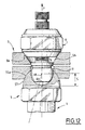
- Figure 12 is a partial view similar to Figure 10 of a variant of the device, modified so as to practically not ensure significant angular recall of the bone anchoring element during Tightening.
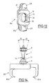
- Figure 13 is an enlarged perspective view of a second embodiment of the connector bracket of FIG. 2.
- Figure 14 is an elevational view on an enlarged scale of a second embodiment of a bone anchoring element of the device.
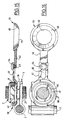
- Figure 15 is a partial sectional view and elevation of a mode of creation of a transverse connection system between two elements bone anchor, which can equip the device of FIGS. 1 to 14.
- Figure 16 is a top view of the cross link system in Figure 15.
- the spinal osteosynthesis device illustrated in Figures 1 to 6 includes several bone anchoring elements, constituted in the example described by bone anchoring elements 1 in respective vertebrae, a longitudinal connecting member between the bone anchoring elements 1 constituted by a vertebral rod 2, and stirrups 3 for connection between the bone anchors 1 and vertebral rods 2, at the rate of a stirrup 3 by bone anchor 1.
- Each element 1 comprises a conical threaded rod 4 for bone anchoring, a head 5 for gripping by a screwing tool 6, a mechanical threaded axis 7 extending the head 5.
- the device is completed by a nut 8 which can be screwed onto the threaded pin 7 to lock the connector bracket 3, the rod together vertebral 2 and the corresponding bone anchoring element 1.
- the gripping head 5 has a shape capable of cooperating with the screwing tool 6, for example a hexagonal contour as shown, adapted to cooperate with a female hexagonal imprint 9 of the tool 6.
- the axis 7 is provided with a terminal ball 11 for articulation in a hemispherical housing 12 of the head 5, in which this ball 11 can be maintained by various assembly and in particular crimping, welding, etc.
- the housing 12 substantially hemispherical allows the ball 11 to rotate and to be mobilized in all plans, thus authorizing an orientation multidirectional of the threaded axis 7.
- connection stirrup 3 are provided with means for blocking in rotation the axis 7 and its ball 11, during tightening or loosening of the nut 8, after introduction of the pin 7 into a corresponding hole 10 of passage through the connection bracket 3.
- these means comprise at least one male rotational stop geometry 13 formed on a flange 14 arranged between the ball joint 11 and the adjoining end of axis 7 and at least one second female rotational geometry illustrated by a flat 15 formed on the inside edge of the hole 10 of the stirrup 3.
- This second flat 15 is adapted so that it can be applied to the first flat 13 after sliding of the stirrup 3 on the threaded axis 7.
- the flange 14 thus has two stop geometries diametrically opposed 13, only one of these geometries 13 being visible in the drawings.
- the collar 14 thus provided with the two geometries 13 can be adjusted in the corresponding connector stirrup 3 if the assembly is used with a vertebral rod 2, or in a plate 16 having rotational stop geometries (edges of holes 38, 41, 43 in Figs. 8 and 9) similar 13 ( Figures 8 and 9) if a plate 16 is used in place of the rod 2 as a longitudinal connecting member between the screws 1.
- the axis 7 has a first threaded portion cylindrical 17, a narrowing 18 constituting an initiation zone of rupture, a second cylindrical threaded portion 19 extended by a part terminal 21 smooth and constituting a male form of suitable profile, by example in a half moon with a rotational stop geometry, hereinafter the flat 22 ( Figure 2).
- This male form 21 is adapted to be able to cooperate with a female shape 20 complementary to the tool 6, formed in the end of a sleeve 24 mounted to slide axially inside a socket 25, at the end of which the female imprint is arranged hexagonal 9 (figure 1).
- the rupture initiation zone 18 preferably has a stop geometry identical to flat 22. This arrangement makes it possible to lock in rotation of the ball joint 11, during an implant recovery operation, using tool 6.
- the socket of the male form 21 with its rotational stop geometry can be a flat 22 in the female form conjugated 20 with application of the flats 22 and 23 against each other, makes it possible to block the axis threaded 7 in rotation during the screwing of nut 8 on threaded portions 19 and 17 from axis 7.
- the axis 7 breaks into two parts. in order to remove the threaded portion 19.
- the second portion 19 having the function only guide the descent of the nut 8 to the stirrup 3 ( Figure 3).
- the nesting of the male 22 and female flats 23 of the sleeve 24 ensures the rotation of the ball joint 11 in its housing 12,
- the connector stirrup 3 is made up of two branches 26, 27 folded one on the other and separated by a longitudinal slot 28. the hole 10 of passage of the axis 7 being thus formed in the branches 26, 27 on either side of the slot 28.
- the two branches 26, 27 are connected by one or two connectors rounded 29 which delimits one or two cylindrical housings 31 in which can be introduced one or two cylindrical rods 2 ( Figure 13).
- FIGS. 10 and 11 illustrate in more detail the embodiment of the device which has just been described with reference to FIGS. 1 to 3.
- the sphere or ball 11 of the anchoring element bone 1 and the spherical cap 57 have centers of rotation respective R1 and R2, distinct and separated by a spacing S.
- the surface of the cap 57 of head 5 is hemispherical and interrupted in its polar region to receive the ball 11, and the spherical surface 55 associated with the stirrup 3, same radius of curvature as the surface of the hemispherical cap 57, completely covers the latter.
- the support taken on the upper part of the gripping head 5 ensures that connector stirrup system 3 and bone anchoring element 1 a function of recall of the latter in the axis XX of the clamping nut 8 and of the threaded rod 7 during the tightening operation by the element 8.
- the element 8 nut for example
- the element 8 whose skirt 8a comes apply to the conical wall 56 of the recess of the nut 8
- produces a tensile force F (figure 10)
- a torque C (figure 11) of return from the bone anchor 4 towards the longitudinal axis XX of the tightening 8 and of the threaded axis 7 by a force orthogonal to this axis.
- the spherical surface 55a only partially covers the spherical surface of the cap 57 because the spherical bearing 55a is interrupted clearly before the equator of the cap 57.
- the tensile force F produced by the tightening of the nut 8 immobilizes the connector stirrup 3 by surface contact, while retaining the orientation of the bone anchoring element 1.
- FIG. 13 illustrates an embodiment of the clip connector 3a wherein it comprises, on either side of the hole 10, two rounded fittings 29, 29 has delimiting two respective housings 31, 31 is adapted to receive longitudinal connecting members such as vertebral rods.
- Figure 14 illustrates a second embodiment of the element bone anchor, here constituted by a lamar hook 60 replacing the rod threaded 4 of the previous embodiment, the rest of the device also being similar to that of FIGS. 1 and 2, in particular the head 5 for gripping by a screwing tool 6 and the threaded axis 7.
- the lamar hook 6 consists of manner known per se by two clamps 60a, 60b with curved end and adjustable relative spacing.
- FIGS 15 and 16 illustrate a possible embodiment of a transverse connection system between bone anchoring elements (1 or 31 or 60).
- This connection system is formed by a pair of flared cups 58, 59, the bottom of which is pierced with an opening 66 for passage of the threaded axis 7.
- Each cup 58, 59 is made in one piece with a respective transverse tab 61, 62, the relative position, and therefore the spacing between the bowls, being adjustable. This adjustment can be obtained for example by means of a screw-nut assembly 63, 64 passing through an elongated lumen 65 of a tab 61 and a tapped hole of the second tab 62.
- Each cup 58, 59 is interposed between a connector bracket 3 (or 3 a ) and a corresponding clamping element 8, which is screwed into the bowl by resting on its conical wall 67, 68 by its conical skirt 8a.
- the orientability of the bone anchoring element 1 relative to the axis XX, with reminder (figures 10, 11) or without angular reminder (figure 12), can also be obtained with a similar geometrically complex recess made in a plate such as 16 ( Figures 8 and 9, orifice 41, 43).
- the axis 7 is oriented towards the connector 3 corresponding, previously mounted on a vertebral rod 2.
- the tool 6 makes it possible to block the axis 7 in rotation thanks to the sleeve 24 while the outer sleeve 25 makes it possible to screw the element of tightening 8 to its blocking position of the assembly, the geometry or geometries rotational stop 13 of the flange 14 being applied to the one or more corresponding rotational stop geometries 15 of stirrup 3.
- Figure 4 illustrates a reduction maneuver.
- the vertebral rod 2 was curved in the sagittal plane to reproduce the curvature of the lordosis that one wish to restore.
- the connector stirrups 3 are threaded on the rod 2 which, by through the stirrups 3, is guided step by step, but without effort, because the ball joint 11 of each bone anchoring element 1 makes it possible to direct the threaded axis extra pedicle 7 towards stirrup 3, before undertaking to bring rod 2 to spinal contact - namely in the example shown a dorso-lumbar segment: sacrum S and lumbar vertebrae L5, L4, L3, L2.
- the lowering of the stirrup 3 along the threaded axis 7 constituting the movable portion of the implant is made using the clamping element 8 (nut), using the key constituted by the tool 6, preventing the ball 11 from turning on itself as previously explained.
- Caliper 3 comes from its underside join the flange 14 suitably oriented, the two stop geometries rotational 22 (flats) 23 meet, thus ensuring the locking of the ball joint 11. Indeed, once facing the flat 15 of the stirrup 3, the flange 14 does not can no longer rotate around its axis.
- the two stop geometries rotational male 22 and female 15 are opposite one another, the ball 11 is blocks by itself. The implant became mono-axial.
- Postoperative X-rays of patients with scoliosis lumbar allow to verify that thanks to the osteosynthesis device according to the invention, the pedicle implants 1, seen from the front, are not in the same plan, and that the lumbar lordosis, (in profile) has been restored in a very satisfactory, with in particular the reappearance of a disc asymmetry physiological, essential to create anatomically conditions correct.
- FIG. 7 illustrates a second bone anchoring element 31 (a screw in this example) can be implemented in the device according to the invention, when the latter comprises a plate 16 ( Figures 8 and 9) or stirrups connectors 3.
- the bone anchoring element 31 comprises a threaded anchoring rod 32, a head 33 devoid of ball joint and thus making the piece screw.
- the head 33 consists of a transverse flange 34 and a shape 35 of grip for screwing with a suitable tool, e.g. a form hexagonal.
- a threaded axis 7 similar to that of the bone anchoring element 1 extends the head 33, the assembly being one piece.
- the plate 16 presents in gaze of the sacrum S a terminal part to a circular hole for passage of a single bone anchor 31, then at L5 for a second elongated portion 39 in which an oblong hole 41 is formed allowing to correlatively adjust the position of a bone anchoring element 31 between two positions; finally the plate 16 has a third part 42 of shape elongated in which is formed an oblong passage 43 delimiting three possible positions for the bone anchor element 1 depending on the fit necessary, thanks to three notches formed on the edges of passage 43.
- Plate 16 intended for three segments or spinal stages S, L5, L4, for example, can be replaced by a plate suitable for a number different floors.
- only one bone anchoring element is polyaxial, therefore with ball 11, the other bone anchoring elements 31 being monoaxial.
- Each hole (41 ...) of plate 16 can have the same profile as hole 10 of the bracket connector 3 for the passage of the bone anchoring element (Fig. 10). This profile ensures a recall function of the bone element towards the axis longitudinal of the clamping element and of the threaded axis 7 by a force orthogonal to this axis.
- the collar 34 located in the extension of the intrapedicular portion of the bone anchoring element 1, is fixed (FIGS. 8 and 9). It can usefully provide good support against the vertebra by a so-called effect "console", while a bone anchoring element 1 can usefully serve to segmentally reduce an angle between two bony structures of the spine contiguous.
- the polyaxial screw 1 is left movable at the start of the installation of the clamping element 8 along the threaded axis 7. Then the sleeve 24 with its half-moon shape 23 blocks the ball joint 11. By an adjusted movement, the bone anchor element 1 is thus positioned in one of the three holes of the oblong hole 43.
- the pre-bending of the plate 16 allows the vertebra L4 to reposition itself in lordosis relative to the underlying vertebra, without compromise the locking of the plate 16 - anchor element couple bone 1, thanks to the tolerance of the patella 11.
Abstract
Description
La présente invention a pour objet un dispositif d'ostéosynthèse rachidienne, en particulier dorso-lombaire.The present invention relates to an osteosynthesis device spinal, especially dorso-lumbar.
Plus précisément, l'invention vise un dispositif du type comprenant au moins deux éléments d'ancrage osseux dans des structures osseuses du rachis, un organe de liaison longitudinale entre les éléments d'ancrage osseux, et des étriers de connexion entre les éléments d'ancrage osseux et les organes de liaison entre les vis ; chaque élément d'ancrage osseux comporte une prise d'ancrage osseux, une tête de préhension par un outil de vissage, un axe fileté prolongeant la tête de préhension et un élément de serrage pouvant être monté sur cet axe pour bloquer ensemble le connecteur, l'organe de liaison longitudinale et l'élément d'ancrage osseux correspondant.More specifically, the invention relates to a device of the type comprising at least at least two bone anchors in bone structures of the spine, a longitudinal connecting member between the anchoring elements bone, and connecting stirrups between the bone anchoring elements and the connecting members between the screws; each bone anchor includes a bone anchor, a gripping head with a screwing, a threaded axis extending the gripping head and a clamp that can be mounted on this axis to lock the connector together, the longitudinal connecting member and the corresponding bone anchoring element.
L'ostéosynthèse plurivertébrale, notamment dorso-lombaire, combine le recours à des vis ou des crochets, reliés entre eux par des plaques ou des tiges.Multi-vertebral osteosynthesis, particularly dorso-lumbar, combines the use of screws or hooks, interconnected by plates or rods.
L'utilisation de plaques comportant des évidements adaptés, autorise un certain débattement des vis et le glissement de ces dernières le long d'un axe. Ceci est utile lors d'implantation de vis ayant une divergence dans le plan sagittal.The use of plates with suitable recesses allows a some movement of the screws and their sliding along an axis. This is useful when installing screws with a divergence in the plane sagittal.
L'utilisation d'organes de liaison longitudinale tels que par exemple des tiges permet, en outre, de faire coulisser les éléments d'ancrage osseux, par exemple des vis, le long de l'axe principal de l'organe de liaison longitudinale, de ramener dans le même axe antéro-postérieur, des vis divergentes dans le plan horizontal, et ce, grâce à des effets de dérotation imprimés aux tiges autour d'un axe apicocaudal, c'est-à-dire dans le plan horizontal.The use of longitudinal connecting members such as for example rods also makes it possible to slide the bone anchoring elements, by example of the screws, along the main axis of the longitudinal connecting member, to bring back in the same anteroposterior axis, divergent screws in the horizontal plane, thanks to derotation effects printed on the rods around an apicocaudal axis, that is to say in the horizontal plane.
Cependant, le cintrage de la tige qu'impose cette manoeuvre, doit être effectué entre deux segments vertébraux suffisamment distants. D'autre part, un ou plusieurs cintrages successifs ne s'effectuent que dans le même plan frontal. On aboutit ainsi à transposer une déformation dans un autre plan, orthogonal au premier. However, the bending of the rod imposed by this maneuver must be performed between two sufficiently distant vertebral segments. On the other hand, one or more successive bends are made only in the same plane front. We thus end up transposing a deformation into another plane, orthogonal to the first.
L'ajustement du couple vis pédiculaires-tige, peut conduire à des sollicitations très importantes du système avant son verrouillage définitif. A cet effet, des instruments spécifiques ont été imaginés.Adjusting the pedicle screw-stem couple can lead to very high stresses on the system before it is permanently locked. In this indeed, specific instruments have been devised.
On a également mis au point des vis pédiculaires dont l'axe fileté est prolongé en arrière, afin de pouvoir guider segment par segment la descente de la tige jusqu'à la base d'implantation vertébrale de la vis.We have also developed pedicle screws whose threaded axis is extended behind, in order to guide the descent segment by segment from the rod to the base of the vertebral implantation of the screw.
L'autre intérêt de ce type d'implant pédiculaire rallongé, est d'autoriser indifféremment le recours à une plaque ou à une tige.The other advantage of this type of extended pedicle implant is to allow either the use of a plate or a rod.
Il est des déformations dont le rayon de courbure peut être très court, uni ou bisegmentaire, mais cependant combiné dans les trois plans, sagittal, horizontal et frontal. Le simple cintrage monoplanaire d'une tige, amenée progressivement à quai, ou en effectuant un mouvement global de dérotation, n'est alors plus adapté.There are deformations whose radius of curvature can be very short, united or bisegmental, but however combined in the three planes, sagittal, horizontal and frontal. The simple monoplane bending of a rod, brought gradually at the quay, or by carrying out a global derotation movement, is no longer suitable.
En effet, la réduction par rotation de la tige en cas de cintrage dans deux plans est prohibée par les lois mécaniques.Indeed, the reduction by rotation of the rod in the event of bending in two plans is prohibited by mechanical laws.
La réduction d'une déformation à grand rayon, dans ces conditions, est tri-planaire, mais en aucun cas séquentielle, et encore moins sélective.The reduction of a large radius deformation under these conditions is tri-planar, but in no way sequential, and even less selective.
Ces déformations courtes, partiellement réductibles, doivent être considérées segment par segment, et surtout plan par plan, avant d'envisager toute manoeuvre de réduction, notamment partielle.These short, partially reducible deformations must be considered segment by segment, and especially plan by plan, before considering any reduction maneuver, in particular partial.
Une vertèbre isolément décalée dans les plans, frontal, sagittal et horizontal, doit être mise en condition de subir une réduction dans un seul plan si cela est nécessaire, voire même en vue d'être solidarisée telle qu'elle au segment adjacent, sans autre contrainte que celle induite par la neutralisation.A vertebra isolated in offset in the planes, frontal, sagittal and horizontal, must be prepared to undergo reduction in a single plan if necessary, or even in order to be united as it to the adjacent segment, with no other constraint than that induced by the neutralization.
Pour résoudre cette équation, des vis pédiculaires munies d'un système à "rotule", ont été imaginées et mises au point.To solve this equation, pedicle screws fitted with a system with "ball joint", have been imagined and developed.
Ainsi, la tête d'une vis peut être coiffée d'un élément en forme de "U", ainsi dénommé "tulipe", qui acquiert une mobilité autour de l'axe principal de la vis.Thus, the head of a screw can be capped with a "U" shaped element, thus called "tulip", which acquires mobility around the main axis of the screw.
Le débattement obtenu autorise, dans certaines limites, de se soustraire aux conséquences d'un décalage angulaire dans le plan horizontal et/ou frontal de l'alignement pédiculaire. The clearance obtained allows, within certain limits, to evade the consequences of an angular shift in the horizontal plane and / or frontal of pedicle alignment.
Dans ces conditions, le cintrage de la tige n'est plus un artifice servant à aligner tant bien que mal un montage mal axé frontalement.Under these conditions, the bending of the rod is no longer a device used to somehow align a poorly oriented front assembly.
Le chirurgien se trouvé libéré de cette énorme contrainte et peut implanter les vis pédiculaires dans l'axe qu'impose la topographie de la vertèbre pathologique.The surgeon finds himself freed from this enormous constraint and can implant the pedicle screws in the axis imposed by the topography of the pathological vertebra.
La statique vertébrale sagittale régionale est respectée grâce à un cintrage monoplanaire, visant à la restitution de l'équilibre sagittal. Différentes solutions mécaniques sont proposées, par, notamment, emboítements successifs d'éléments aboutissant à la solidarisation du trinôme, vis, rotule, tige.The regional sagittal vertebral statics are respected thanks to a monoplanar bending, aimed at restoring the sagittal balance. different mechanical solutions are proposed, by, in particular, sockets successive elements leading to the joining of the trinomial, screw, ball joint, rod.
Des évidements géométriquement complexes, et l'emboítement d'une série d'éléments, permettent de reproduire les avantages de l'élément vis-tulipe à rotule, précédemment décrit.Geometrically complex recesses, and the nesting of a series of elements, allow to reproduce the advantages of the vis-tulip element with ball joint, previously described.
Malgré le progrès considérable que représente cette alternative, il
convient d'en faire une analyse critique, qui se résumera en trois points.
Conformément à l'invention, l'axe fileté est pourvu d'une rotule terminale d'articulation dans un logement d'une calotte sphérique de la tête de préhension, permettant une orientation pluridirectionnelle de l'axe fileté et un positionnement de l'organe de liaison longitudinale adaptés à la configuration du segment vertébral recevant les éléments d'ancrage osseux, et l'axe fileté, l'organe de liaison longitudinale et/ou chaque étrier de connexion sont munis de moyens de blocage pour bloquer en rotation l'axe et sa rotule après introduction de l'axe fileté dans un trou correspondant de passage à travers l'organe de liaison longitudinale ou à travers l'étrier de connexion.According to the invention, the threaded axis is provided with a terminal ball joint of articulation in a housing of a spherical cap of the head of gripping, allowing a multidirectional orientation of the threaded axis and a positioning of the longitudinal link member adapted to the configuration of the vertebral segment receiving the bone anchoring elements, and the threaded axis, the longitudinal connection member and / or each connection bracket are provided blocking means for blocking in rotation the axis and its ball joint after introduction of the threaded pin into a corresponding hole for passage through the longitudinal connecting member or through the connection bracket.
Avantageusement, lesdits moyens comprennent au moins une géométrie d'arrêt rotationnel formée entre la rotule et l'extrémité contiguë de l'axe fileté, et une seconde géométrie d'arrêt rotationnel ménagée sur le bord intérieur du trou d'un étrier connecteur, cette seconde géométrie étant adaptée pour venir s'appliquer sur la première géométrie après coulissement de l'étrier connecteur sur l'axe fileté.Advantageously, said means comprise at least one geometry rotational stop formed between the ball joint and the contiguous end of the threaded axis, and a second rotational stop geometry formed on the inner edge of the hole of a connector bracket, this second geometry being adapted to come apply to the first geometry after sliding of the stirrup connector on the threaded shaft.
Selon une autre réalisation de l'invention, le dispositif comprend en outre au moins un élément d'ancrage osseux, comportant une forme d'ancrage, une tête présentant une collerette transversale et une forme de préhension, pour le vissage, ainsi qu'un axe fileté prolongeant la tête, l'ensemble étant monobloc.According to another embodiment of the invention, the device further comprises at least one bone anchoring element, comprising an anchoring form, a head with a transverse flange and a grip shape, for screwing, as well as a threaded axis extending the head, the assembly being in one piece.
D'autres particularités et avantages de l'invention apparaítront au cours de la description qui va suivre, faite en référence aux dessins annexés qui en illustrent deux formes de réalisation à titre d'exemples non limitatifs.Other features and advantages of the invention will become apparent during of the description which follows, made with reference to the accompanying drawings which illustrate two embodiments by way of nonlimiting examples.
La figure 1 est une vue en perspective partielle avant assemblage, à échelle agrandie, d'une première forme de réalisation du dispositif d'ostéosynthèse rachidienne selon l'invention.Figure 1 is a partial perspective view before assembly, with enlarged scale, of a first embodiment of the device of spinal osteosynthesis according to the invention.
La figure 2 est une vue en perspective partielle du dispositif de la figure 1, montrant à échelle agrandie, un élément d'ancrage osseux à double filetage et un étrier correspondant de connexion avec une tige vertébrale non représentée, cet élément d'ancrage osseux pouvant être notamment une vis ou un crochet. Figure 2 is a partial perspective view of the device of the Figure 1, showing on an enlarged scale, a double bone anchoring element thread and a corresponding clamp for connection with a non-spinal rod shown, this bone anchoring element can in particular be a screw or a hook.
La figure 3 est une vue en perspective à échelle agrandie du dispositif des figures 1 et 2 assemblées et mises en place sur un segment vertébral.Figure 3 is an enlarged perspective view of the device Figures 1 and 2 assembled and placed on a vertebral segment.
La figure 4 est une vue en élévation antérolatérale d'un segment dorsolombaire avec un dispositif d'ostéosynthèse selon l'invention en cours de montage, certains des étriers connecteurs équipant une tige vertébrale étant enfilés sur les axes filetés des éléments d'ancrage osseux correspondants préalablement ancrés dans les structures osseuses vertébrales.Figure 4 is an anterolateral elevation view of a dorsolumbar segment with an osteosynthesis device according to the invention during mounting, some of the connector stirrups equipping a vertebral rod being threaded on the threaded axes of the corresponding bone anchoring elements previously anchored in the vertebral bone structures.
La figure 5 est une vue postérieure du segment dorso-lombaire de la figure 4 et du dispositif correspondant installé.Figure 5 is a posterior view of the dorso-lumbar segment of the Figure 4 and the corresponding device installed.
La figure 6 est une vue antérolatérale du dispositif de la figure 5, montrant la lordose lombaire assurée par le cintrage de la tige vertébrale.FIG. 6 is an anterolateral view of the device of FIG. 5, showing the lumbar lordosis ensured by the bending of the vertebral rod.
La figure 7 est une vue en plan d'un élément d'ancrage osseux monobloc, sans rotule, pouvant équiper le dispositif d'ostéosynthèse selon l'invention.Figure 7 is a plan view of a bone anchor monobloc, without ball joint, able to equip the osteosynthesis device according to the invention.
La figure 8 est une vue en élévation postérieure d'un dispositif à plaque de liaison entre les éléments d'ancrage osseux monté sur un segment dorsolombaire.Figure 8 is a rear elevational view of a plate device of connection between the bone anchoring elements mounted on a segment thoracolumbar.
La figure 9 est une vue en élévation dans un plan sagittal du dispositif à plaque de la figure 8, comportant un élément d'ancrage osseux tel que celui de la figure 6.Figure 9 is an elevational view in a sagittal plane of the device to plate of FIG. 8, comprising a bone anchoring element such as that in Figure 6.
La figure 10 est une vue en élévation et coupe partielles à échelle agrandie de l'assemblage d'un élément d'ancrage osseux, d'un étrier connecteur et d'un élément de serrage selon la réalisation des figures 1 à 4, assurant un rappel de l'élément d'ancrage osseux dans l'axe de l'élément de serrage.Figure 10 is a partial sectional elevation and sectional view enlarged assembly of a bone anchor, a stirrup connector and a clamping element according to the embodiment of FIGS. 1 to 4, ensuring a return of the bone anchoring element in the axis of the element of Tightening.
La figure 11 est une vue schématique en élévation, à échelle réduite par rapport à la figure 10, de l'ensemble du dispositif correspondant, illustrant le rappel angulaire de l'élément d'ancrage osseux dans l'axe de l'élément de serrage et de la tige filetée lors du serrage.Figure 11 is a schematic elevational view, on a reduced scale by compared to FIG. 10, of the whole of the corresponding device, illustrating the angular recall of the bone anchoring element in the axis of the tightening and threaded rod when tightening.
La figure 12 est une vue partielle analogue à la figure 10 d'une variante de réalisation du dispositif, modifiée de manière à ne pratiquement pas assurer de rappel angulaire appréciable de l'élément d'ancrage osseux lors du serrage. Figure 12 is a partial view similar to Figure 10 of a variant of the device, modified so as to practically not ensure significant angular recall of the bone anchoring element during Tightening.
La figure 13 est une vue en perspective à échelle agrandie, d'un second mode de réalisation de l'étrier connecteur de la figure 2.Figure 13 is an enlarged perspective view of a second embodiment of the connector bracket of FIG. 2.
La figure 14 est une vue en élévation à échelle agrandie d'un second mode de réalisation d'un élément d'ancrage osseux du dispositif.Figure 14 is an elevational view on an enlarged scale of a second embodiment of a bone anchoring element of the device.
La figure 15 est une vue en coupe partielle et élévation d'un mode de réalisation d'un système de liaison transversale entre deux éléments d'ancrage osseux, pouvant équiper le dispositif des figures 1 à 14.Figure 15 is a partial sectional view and elevation of a mode of creation of a transverse connection system between two elements bone anchor, which can equip the device of FIGS. 1 to 14.
La figure 16 est une vue de dessus du système de liaison transversale de la figure 15.Figure 16 is a top view of the cross link system in Figure 15.
Le dispositif d'ostéosynthèse rachidienne illustré aux figures 1 à 6
comprend plusieurs éléments d'ancrage osseux, constitués dans l'exemple
décrit par des éléments d'ancrage osseux 1 dans des vertèbres respectives,
un organe de liaison longitudinale entre les éléments d'ancrage osseux 1
constitué par une tige vertébrale 2, et des étriers 3 de connexion entre les
éléments d'ancrage osseux 1 et les tiges vertébrales 2, à raison d'un étrier 3
par élément d'ancrage osseux 1.The spinal osteosynthesis device illustrated in Figures 1 to 6
includes several bone anchoring elements, constituted in the example
described by
Chaque élément 1 comporte une tige filetée conique 4 d'ancrage osseux,
une tête 5 de préhension par un outil de vissage 6, un axe fileté mécanique 7
prolongeant la tête 5. Le dispositif est complété par un écrou 8 pouvant être
vissé sur l'axe fileté 7 pour bloquer ensemble l'étrier connecteur 3, la tige
vertébrale 2 et l'élément d'ancrage osseux correspondant 1.Each
La tête de préhension 5 comporte une forme pouvant coopérer avec
l'outil de vissage 6, par exemple un contour hexagonal comme représenté,
adapté pour coopérer avec une empreinte hexagonale femelle 9 de l'outil 6.The
L'axe 7 est pourvu d'une rotule terminale 11 d'articulation dans un
logement hémisphérique 12 de la tête 5, dans lequel cette rotule 11 peut être
maintenue par assemblage divers et notamment sertissage, soudure, etc. Le
logement 12 sensiblement hémisphérique permet à la rotule 11 de tourner et
d'être mobilisée dans tous les plans, autorisant ainsi une orientation
pluridirectionnelle de l'axe fileté 7.The
Ce dernier et l'étrier 3 de connexion sont munis de moyens pour bloquer
en rotation l'axe 7 et sa rotule 11, pendant le serrage ou le desserrage de
l'écrou 8, après introduction de l'axe 7 dans un trou correspondant 10 de
passage à travers l'étrier de connexion 3. Dans la réalisation représentée, ces
moyens comprennent au moins une géométrie d'arrêt rotationnel mâle 13
formée sur une collerette 14 agencée entre la rotule 11 et l'extrémité contiguë
de l'axe 7 et au moins une seconde géométrie rotationnelle femelle illustrée
par un méplat 15 ménagé sur le bord intérieur du trou 10 de l'étrier 3. Ce
second méplat 15 est adapté pour pouvoir venir s'appliquer sur le premier
méplat 13 après coulissement de l'étrier 3 sur l'axe fileté 7.The latter and the
De préférence la collerette 14 présente ainsi deux géométries d'arrêt
rotationnel 13 diamétralement opposées, l'une seulement de ces géométries
13 étant visibles aux dessins. La collerette 14 ainsi munie des deux
géométries 13 peut venir s'ajuster dans l'étrier connecteur correspondant 3 si
le montage est utilisé avec une tige vertébrale 2, ou dans une plaque 16 ayant
des géométries d'arrêt rotationnel (bords des trous 38, 41, 43 aux Fig. 8 et 9)
similaires 13 (figures 8 et 9) si l'on utilise une plaque 16 à la place de la tige 2
comme organe de liaison longitudinale entre les vis 1.Preferably the
Au-delà de la collerette 14, l'axe 7 comporte une première portion filetée
cylindrique 17, un rétrécissement 18 constituant une zone d'amorce de
rupture, une seconde portion filetée cylindrique 19 prolongée par une partie
terminale 21 lisse et constituant une forme mâle de profil approprié, par
exemple en demi-lune avec une géométrie d'arrêt rotationnel, ci-après le
méplat 22 (figure 2). Cette forme mâle 21 est adaptée pour pouvoir coopérer
avec une forme femelle 20 complémentaire de l'outil 6, ménagée dans
l'extrémité d'un manchon 24 monté coulissant axialement à l'intérieur d'une
douille 25, à l'extrémité de laquelle est agencée l'empreinte femelle
hexagonale 9 (figure 1).Beyond the
La zone d'amorce de rupture 18 a de préférence une géométrie d'arrêt
rotationnel identique au méplat 22. Ce agencement permet de bloquer en
rotation la rotule 11, lors d'une opération de reprise de l'implant, à l'aide de
l'outil 6.The
L'emboítement de la forme mâle 21 avec sa géométrie d'arrêt rotationnel
pouvant être un méplat 22 dans la forme femelle conjuguée 20 avec
application des méplats 22 et 23 l'un contre l'autre, permet de bloquer l'axe
fileté 7 en rotation pendant le vissage de l'écrou 8 sur les portions filetées 19
et 17 de l'axe 7.The socket of the
Par ailleurs une fois le montage terminé, c'est au niveau du
rétrécissement 18 que s'opère la cassure de l'axe 7 en deux parties. afin de
retirer la portion filetée 19. Ainsi, seule la portion filetée 17 fait partie
intégrante du montage définitif, la seconde portion 19 ayant pour fonction
uniquement de guider la descente de l'écrou 8 jusqu'à l'étrier 3 (figure 3).
Durant la descente de l'écrou 8, l'emboítement des méplats mâle 22 et femelle
23 du manchon 24 assure le blocage en rotation de la rotule 11 dans son
logement 12,Furthermore, once the assembly is completed, it is at the level of
narrowing 18 that the
L'étrier connecteur 3 est constitué de deux branches 26, 27 repliées l'une
sur l'autre et séparées par une fente longitudinale 28 . le trou 10 de passage
de l'axe 7 étant ainsi formé dans les branches 26, 27 de part et d'autre de la
fente 28. Les deux branches 26, 27 sont reliées par un ou deux raccords
arrondis 29 qui délimite un ou deux logements cylindriques 31 dans lequel
peuvent être introduites une ou deux tiges cylindriques 2 (figure 13).The
Les figures 10 et 11 illustrent plus en détail la réalisation du dispositif qui vient d'être décrit en référence aux figures 1 à 3.Figures 10 and 11 illustrate in more detail the embodiment of the device which has just been described with reference to FIGS. 1 to 3.
En effet, elles montrent que la sphère ou rotule 11 de l'élément d'ancrage
osseux 1 et la calotte sphérique 57 présentent des centres de rotation
respectifs R1 et R2, distincts et séparés par un écartement S. La surface de la
calotte 57 de la tête 5 est hémisphérique et interrompue dans sa zone polaire
pour recevoir la rotule 11, et la surface sphérique 55 associée de l'étrier 3, de
même rayon de courbure que la surface de la calotte hémisphérique 57,
recouvre complètement cette dernière.Indeed, they show that the sphere or
L'appui pris sur la partie supérieure de la tête de préhension 5 assure au
système étrier connecteur 3 et élément d'ancrage osseux 1 une fonction de
rappel de ce dernier dans l'axe XX de l'écrou de serrage 8 et de la tige filetée
7 lors de la manoeuvre de serrage par l'élément 8. En effet. au moment de
cette manoeuvre, l'élément 8 (écrou par exemple) dont la jupe 8a vient
s'appliquer sur la paroi conique 56 de l'évidement de l'écrou 8, produit une
force de traction F (figure 10), qui détermine un couple C (figure 11) de rappel
de l'élément d'ancrage osseux 4 vers l'axe longitudinal XX de l'élément de
serrage 8 et de l'axe fileté 7 par une force orthogonale à cet axe.The support taken on the upper part of the
Dans la forme de réalisation illustrée à la figure 12, la surface sphérique
55a ne recouvre que partiellement la surface sphérique de la calotte 57 car la
portée sphérique 55a est interrompue nettement avant l'équateur de la calotte
57. De ce fait, la force de traction F produite par le serrage de l'écrou 8,
immobilise l'étrier connecteur 3 par contact surfacique, tout en conservant
l'orientation de l'élément d'ancrage osseux 1.In the embodiment illustrated in Figure 12, the
Cette possibilité d'agir avec des connecteurs différents pouvant faire varier le réalignement, autorise une planification des corrections, sans recours à des outils complémentaires.This possibility of acting with different connectors which can make vary the realignment, authorizes a correction planning, without recourse additional tools.
La figure 13 illustre une forme de réalisation de l'étrier connecteur 3a
dans laquelle celui-ci comporte, de part et d'autre du trou 10, deux raccords
arrondis 29, 29a délimitant deux logements respectifs 31, 31a adaptés pour
recevoir des organes de liaison longitudinale tels que des tiges vertébrales.13 illustrates an embodiment of the clip connector 3a wherein it comprises, on either side of the
La figure 14 illustre un second mode de réalisation de l'élément
d'ancrage osseux, ici constitué par un crochet lamaire 60 remplaçant la tige
filetée 4 de la réalisation précédente, le reste du dispositif étant par ailleurs
similaire à celui des figures 1 et 2, notamment la tête 5 de préhension par un
outil de vissage 6 et l'axe fileté 7. Le crochet lamaire 6 est constitué de
manière connue en soi par deux pinces 60a, 60b à extrémité recourbée et
d'écartement relatif réglable.Figure 14 illustrates a second embodiment of the element
bone anchor, here constituted by a
Les figures 15 et 16 illustrent un mode de réalisation possible d'un
système de liaison transversale entre des éléments d'ancrage osseux (1 ou 31
ou 60). Ce système de liaison est formé par une paire de cuvettes 58, 59
évasées, dont le fond est percé d'une ouverture 66 de passage de l'axe
fileté 7. Chaque cuvette 58, 59 est réalisée monobloc avec une patte
transversale respective 61, 62, la position relative, et donc l'écartement entre
les cuvettes, étant réglable. Ce réglage peut être obtenu par exemple au
moyen d'un ensemble vis-écrou 63, 64 traversant une lumière allongée 65
d'une patte 61 et un trou taraudé de la deuxième patte 62. Chaque cuvette 58,
59 est interposée entre un étrier connecteur 3 (ou 3a) et un élément de
serrage correspondant 8, qui vient se visser dans la cuvette en prenant appui
sur sa paroi conique 67, 68 par sa jupe conique 8a.Figures 15 and 16 illustrate a possible embodiment of a transverse connection system between bone anchoring elements (1 or 31 or 60). This connection system is formed by a pair of flared
L'orientabilité de l'élément d'ancrage osseux 1 par rapport à l'axe XX,
avec rappel (figures 10, 11) ou sans rappel angulaire (figure 12), peut aussi
être obtenue avec un évidement géométriquement complexe similaire réalisé
dans une plaque telle que 16 (figures 8 et 9, orifice 41, 43).The orientability of the
Une fois l'élément d'ancrage 4 préalablement appliqué à la structure
d'une vertèbre, par exemple lombaire, on oriente l'axe 7 vers le connecteur 3
correspondant, préalablement monté sur une tige vertébrale 2. Une fois cette
introduction effectuée, l'outil 6 permet de bloquer l'axe 7 en rotation grâce au
manchon 24 tandis que la douille extérieure 25 permet de visser l'élément de
serrage 8 jusqu'à sa position de blocage de l'ensemble, la ou les géométries
d'arrêt rotationnel 13 de la collerette 14 étant appliquées sur la ou les
géométries d'arrêt rotationnel correspondantes 15 de l'étrier 3.Once the anchor element 4 has previously been applied to the structure
a vertebra, for example lumbar, the
La figure 4 illustre une manoeuvre de réduction. La tige vertébrale 2 a été
cintrée dans le plan sagittal pour reproduire la courbure de la lordose que l'on
souhaite rétablir. Les étriers connecteurs 3 sont enfilés sur la tige 2 qui, par
l'intermédiaire des étriers 3, est guidée pas à pas, mais sans effort, car la
rotule 11 de chaque élément d'ancrage osseux 1 permet de diriger l'axe fileté
extra pédiculaire 7 vers l'étrier 3, avant d'entreprendre d'amener la tige 2 au
contact de la colonne vertébrale- à savoir dans l'exemple représenté un
segment dorso-lombaire : sacrum S et vertèbres lombaires L5, L4, L3, L2. La
descente de l'étrier 3 le long de l'axe fileté 7 constituant la portion mobile de
l'implant s'effectue grâce à l'élément de serrage 8 (écrou), à l'aide de la clé
constituée par l'outil 6, empêchant la rotule 11 de tourner sur elle-même
comme expliqué précédemment. L'étrier 3 vient par sa face inférieure
rejoindre la collerette 14 convenablement orientée, les deux géométries d'arrêt
rotationnel 22 (méplats) 23 se rejoignent, assurant ainsi le blocage de la rotule
11. En effet, une fois en regard du méplat 15 de l'étrier 3, la collerette 14 ne
peut plus tourner autour de son axe. Lorsque les deux géométries d'arrêt
rotationnel mâle 22 et femelle 15 sont en face l'un de l'autre, la rotule 11 se
bloque d'elle-même. L'implant est devenu mono-axial. Figure 4 illustrates a reduction maneuver. The
Dans le montage lombosacré illustré à la figure 6, intéressant le sacrum
S et les quatre premières vertèbres lombaires, on voit que la lordose
physiologique a été rétablie grâce à la courbure de la tige 2 dans le plan
sagittal, les portions extra-pédiculaires constituées par les axes 7 étant
corrélativement orientées pour s'adapter à ce cintrage. Une fois le montage
verrouillé, la portion postérieure 19 de chaque axe fileté 7 est sectionnée
aisément, grâce à la réduction de section formée par la zone d'amorce de
rupture 18. Les radios postopératoires de patients présentant une scoliose
lombaire permettent de vérifier que grâce au dispositif d'ostéosynthèse selon
l'invention, les implants pédiculaires 1, vus de face, ne sont pas dans le même
plan, et que la lordose lombaire, (de profil) a été rétablie de manière très
satisfaisante, avec notamment réapparition d'une asymétrie discale
physiologique, indispensable pour créer des conditions anatomiquement
correctes.In the lumbosacral arrangement illustrated in Figure 6, concerning the sacrum
S and the first four lumbar vertebrae, we see that the lordosis
physiological has been restored thanks to the curvature of the
La figure 7 illustre un second élément d'ancrage osseux 31 (une vis dans
cet exemple) pouvant être mis en oeuvre dans le dispositif selon l'invention,
lorsque celui-ci comprend une plaque 16 (figures 8 et 9) ou des étriers
connecteurs 3.FIG. 7 illustrates a second bone anchoring element 31 (a screw in
this example) can be implemented in the device according to the invention,
when the latter comprises a plate 16 (Figures 8 and 9) or
L'élément d'ancrage osseux 31 comporte une tige filetée d'ancrage 32,
une tête 33 dépourvue de rotule et rendant ainsi la vis monobloc. La tête 33
est constituée d'une collerette transversale 34 et d'une forme 35 de
préhension pour le vissage par un outil approprié, par exemple une forme
hexagonale. Un axe fileté 7 similaire à celui de l'élément d'ancrage osseux 1
prolonge la tête 33, l'ensemble étant mono-pièce. La plaque 16 présente en
regard du sacrum S une partie terminale à un trou circulaire de passage d'un
élément d'ancrage osseux unique 31, puis au niveau de L5 une seconde
portion 39 allongée dans laquelle est formé un trou oblong 41 permettant
d'ajuster corrélativement la position d'un élément d'ancrage osseux 31 entre
deux positions ; enfin la plaque 16 comporte une troisième partie 42 de forme
allongée dans laquelle est ménagé un passage oblong 43 délimitant trois
positions possibles pour l'élément d'ancrage osseux 1 selon l'ajustement
nécessaire, grâce à trois échancrures ménagées sur les bords du passage 43. The
La plaque 16, destinée à trois segments ou étages rachidiens S, L5, L4,
par exemple, peut être remplacée par une plaque adaptée à un nombre
différent d'étages. Par exemple dans le montage à trois étages des figures 8
et 9, seul un élément d'ancrage osseux est polyaxial, donc à rotule 11, les
autres éléments d'ancrage osseux 31 étant monoaxiaux. Chaque trou (41 ...)
de la plaque 16 peut avoir le même profil que le trou 10 de l'étrier
connecteur 3 pour le passage de l'élément d'ancrage osseux (Fig. 10). Ce
profil permet d'assurer une fonction de rappel de l'élément osseux vers l'axe
longitudinal de l'élément de serrage et de l'axe fileté 7 par une force
orthogonale à cet axe. La collerette 34 située dans le prolongement de la
portion intrapédiculaire de l'élément d'ancrage osseux 1, est fixe (figures 8 et
9). Elle peut utilement assurer un bon appui contre la vertèbre par un effet dit
"console", alors qu'un élément d'ancrage osseux 1 peut utilement servir à
réduire segmentairement un angle entre deux structures osseuses du rachis
contiguës.
La vis polyaxiale 1 est laissée mobile au début de la mise en place de
l'élément de serrage 8 le long de l'axe fileté 7. Ensuite le manchon 24 avec sa
forme en demi-lune 23 vient bloquer la rotule 11. Par un mouvement ajusté,
on vient ainsi positionner l'élément d'ancrage osseux 1 dans l'un des trois
orifices du trou oblong 43. Le précintrage de la plaque 16 permet à la vertèbre
L4 de se repositionner en lordose par rapport à la vertèbre sous-jacente, sans
compromettre le verrouillage du couple plaque 16 - élément d'ancrage
osseux 1, grâce à la tolérance de la rotule 11.The
Il est possible d'utiliser une plaque pour deux structures osseuses du rachis lombaires seulement. Le précintrage de cette plaque permet de ramener la vertèbre en bascule postérieure et donc de recréer une asymétrie discale physiologique, dans le cadre notamment du traitement chirurgical d'une pathologie dite de "dos plat".It is possible to use a plate for two bone structures of the lumbar spine only. Pre-bending this plate allows bring the vertebra backwards and thus recreate an asymmetry physiological disc, in particular in the context of surgical treatment a pathology called "flat back".
Outre les avantages techniques précédemment mentionnés, le dispositif d'ostéosynthèse rachidienne selon l'invention présente les avantages suivants :
- guidage de l'élément d'ancrage osseux 1, 31
par un instrument 6 normo-axant instantanément la partie pédiculaire 4, 32 de l'élément d'ancrage osseux 1 et son prolongement multiaxial 7. - Possibilité de réduction monoplanaire ou combinée dans les trois plans.
- Affranchissement de certaines séquences opératoires.
- Réduction vertébrale par traction antéro-postérieure à l'aide de l'élément d'ancrage osseux, directement sans instrument complémentaire.
- Maítrise de l'orientabilité du système susceptible d'être conservée ou
neutralisée indifféremment en fonction des exigences per-opératoires, grâce
aux caractéristiques dimensionnelles et fonctionnelles des étriers
connecteurs 3 (combinaison de la portée sphérique 55
ou 55a avec la calotte sphérique 57).
- guiding the
bone anchoring element instrument 6 normo-instantaneously instantiating thepedicle part 4, 32 of thebone anchoring element 1 and itsmultiaxial extension 7. - Possibility of monoplanar or combined reduction in the three planes.
- Postage of certain operating sequences.
- Vertebral reduction by anteroposterior traction using the bone anchoring element, directly without additional instrument.
- Control of the orientability of the system capable of being preserved or neutralized indifferently depending on the peroperative requirements, thanks to the dimensional and functional characteristics of the connector stirrups 3 (combination of the
spherical bearing
Claims (8)
Applications Claiming Priority (3)
| Application Number | Priority Date | Filing Date | Title |
|---|---|---|---|
| IE970411 | 1997-06-03 | ||
| IE970411A IES970411A2 (en) | 1997-06-03 | 1997-06-03 | Pluridirectional and modulable vertebral osteosynthesis device of small overall size |
| EP98929473A EP0986339B1 (en) | 1997-06-03 | 1998-06-03 | Multidirectional adaptable vertebral osteosynthesis device with reduced space requirement |
Related Parent Applications (1)
| Application Number | Title | Priority Date | Filing Date |
|---|---|---|---|
| EP98929473A Division EP0986339B1 (en) | 1997-06-03 | 1998-06-03 | Multidirectional adaptable vertebral osteosynthesis device with reduced space requirement |
Publications (3)
| Publication Number | Publication Date |
|---|---|
| EP1415603A2 true EP1415603A2 (en) | 2004-05-06 |
| EP1415603A3 EP1415603A3 (en) | 2005-07-06 |
| EP1415603B1 EP1415603B1 (en) | 2008-04-23 |
Family
ID=11041500
Family Applications (3)
| Application Number | Title | Priority Date | Filing Date |
|---|---|---|---|
| EP98929473A Expired - Lifetime EP0986339B1 (en) | 1997-06-03 | 1998-06-03 | Multidirectional adaptable vertebral osteosynthesis device with reduced space requirement |
| EP03025177A Expired - Lifetime EP1415603B1 (en) | 1997-06-03 | 1998-06-03 | Multidirectional adaptable vertebral osteosynthesis device with reduced space requirement |
| EP03025168A Expired - Lifetime EP1415602B1 (en) | 1997-06-03 | 1998-06-03 | Multidirectional adaptable vertebral osteosynthesis device with reduced space requirement |
Family Applications Before (1)
| Application Number | Title | Priority Date | Filing Date |
|---|---|---|---|
| EP98929473A Expired - Lifetime EP0986339B1 (en) | 1997-06-03 | 1998-06-03 | Multidirectional adaptable vertebral osteosynthesis device with reduced space requirement |
Family Applications After (1)
| Application Number | Title | Priority Date | Filing Date |
|---|---|---|---|
| EP03025168A Expired - Lifetime EP1415602B1 (en) | 1997-06-03 | 1998-06-03 | Multidirectional adaptable vertebral osteosynthesis device with reduced space requirement |
Country Status (9)
| Country | Link |
|---|---|
| US (2) | US6267765B1 (en) |
| EP (3) | EP0986339B1 (en) |
| JP (1) | JP4399554B2 (en) |
| CA (1) | CA2292748C (en) |
| DE (3) | DE69839406T2 (en) |
| ES (3) | ES2295496T3 (en) |
| IE (1) | IES970411A2 (en) |
| PT (3) | PT986339E (en) |
| WO (1) | WO1998055038A1 (en) |
Cited By (1)
| Publication number | Priority date | Publication date | Assignee | Title |
|---|---|---|---|---|
| WO2012029025A1 (en) * | 2010-09-01 | 2012-03-08 | Medicrea International | Vertebral osteosynthesis assembly formed by a vertebral osteosynthesis material and instruments for placing said material |
Families Citing this family (277)
| Publication number | Priority date | Publication date | Assignee | Title |
|---|---|---|---|---|
| US6652527B2 (en) * | 1998-10-20 | 2003-11-25 | St. Francis Medical Technologies, Inc. | Supplemental spine fixation device and method |
| US6283967B1 (en) | 1999-12-17 | 2001-09-04 | Synthes (U.S.A.) | Transconnector for coupling spinal rods |
| FR2796546B1 (en) * | 1999-07-23 | 2001-11-30 | Eurosurgical | POLYAXIAL CONNECTOR FOR SPINAL IMPLANT |
| DE19944120B4 (en) * | 1999-09-15 | 2008-08-28 | Ulrich Gmbh & Co. Kg | Bone screw for variable angle connection with a side member |
| JP2004516040A (en) * | 2000-06-30 | 2004-06-03 | リトラン、スティーブン | Multi-shaft coupling device and method |
| AU2006200772B2 (en) * | 2000-06-30 | 2009-04-02 | Stephen Ritland | Polyaxial connection device and method |
| US7056321B2 (en) | 2000-08-01 | 2006-06-06 | Endius, Incorporated | Method of securing vertebrae |
| US7985247B2 (en) * | 2000-08-01 | 2011-07-26 | Zimmer Spine, Inc. | Methods and apparatuses for treating the spine through an access device |
| US7833250B2 (en) | 2004-11-10 | 2010-11-16 | Jackson Roger P | Polyaxial bone screw with helically wound capture connection |
| US6554831B1 (en) * | 2000-09-01 | 2003-04-29 | Hopital Sainte-Justine | Mobile dynamic system for treating spinal disorder |
| US7166073B2 (en) | 2000-09-29 | 2007-01-23 | Stephen Ritland | Method and device for microsurgical intermuscular spinal surgery |
| FR2816196B1 (en) * | 2000-11-07 | 2003-01-03 | Medicrea | VERTEBRAL ARTHRODESIS MATERIAL |
| FR2816195B1 (en) * | 2000-11-07 | 2003-01-03 | Medicrea | VERTEBRAL ARTHRODESIS MATERIAL |
| US6802844B2 (en) * | 2001-03-26 | 2004-10-12 | Nuvasive, Inc | Spinal alignment apparatus and methods |
| US6511481B2 (en) | 2001-03-30 | 2003-01-28 | Triage Medical, Inc. | Method and apparatus for fixation of proximal femoral fractures |
| US6887243B2 (en) | 2001-03-30 | 2005-05-03 | Triage Medical, Inc. | Method and apparatus for bone fixation with secondary compression |
| FR2823095B1 (en) * | 2001-04-06 | 2004-02-06 | Ldr Medical | RACHIS OSTEOSYNTHESIS DEVICE AND PLACEMENT METHOD |
| US8292926B2 (en) | 2005-09-30 | 2012-10-23 | Jackson Roger P | Dynamic stabilization connecting member with elastic core and outer sleeve |
| US10258382B2 (en) | 2007-01-18 | 2019-04-16 | Roger P. Jackson | Rod-cord dynamic connection assemblies with slidable bone anchor attachment members along the cord |
| US8353932B2 (en) | 2005-09-30 | 2013-01-15 | Jackson Roger P | Polyaxial bone anchor assembly with one-piece closure, pressure insert and plastic elongate member |
| US7862587B2 (en) | 2004-02-27 | 2011-01-04 | Jackson Roger P | Dynamic stabilization assemblies, tool set and method |
| US10729469B2 (en) | 2006-01-09 | 2020-08-04 | Roger P. Jackson | Flexible spinal stabilization assembly with spacer having off-axis core member |
| ATE495709T1 (en) * | 2001-09-28 | 2011-02-15 | Stephen Ritland | CONNECTING ROD FOR A POLYAXIAL SYSTEM WITH SCREW OR HOOK |
| US7261713B2 (en) | 2001-10-09 | 2007-08-28 | Synthes (Usa) | Adjustable fixator |
| FR2831048B1 (en) * | 2001-10-18 | 2004-09-17 | Ldr Medical | PROGRESSIVE APPROACH OSTEOSYNTHESIS DEVICE AND PRE-ASSEMBLY PROCESS |
| FR2833151B1 (en) | 2001-12-12 | 2004-09-17 | Ldr Medical | BONE ANCHORING IMPLANT WITH POLYAXIAL HEAD |
| US20040006342A1 (en) * | 2002-02-13 | 2004-01-08 | Moti Altarac | Posterior polyaxial plate system for the spine |
| US7163538B2 (en) * | 2002-02-13 | 2007-01-16 | Cross Medical Products, Inc. | Posterior rod system |
| WO2003073908A2 (en) | 2002-02-20 | 2003-09-12 | Stephen Ritland | Pedicle screw connector apparatus and method |
| FR2838041B1 (en) * | 2002-04-04 | 2004-07-02 | Kiscomedica | SPINAL OSTEOSYNTHESIS SYSTEM |
| US6966910B2 (en) | 2002-04-05 | 2005-11-22 | Stephen Ritland | Dynamic fixation device and method of use |
| WO2003094699A2 (en) | 2002-05-08 | 2003-11-20 | Stephen Ritland | Dynamic fixation device and method of use |
| US6733502B2 (en) * | 2002-05-15 | 2004-05-11 | Cross Medical Products, Inc. | Variable locking spinal screw having a knurled collar |
| US6793678B2 (en) | 2002-06-27 | 2004-09-21 | Depuy Acromed, Inc. | Prosthetic intervertebral motion disc having dampening |
| FR2842093B1 (en) * | 2002-07-12 | 2005-04-15 | Scient X | BONE ANCHORING DEVICE WITH SPHERICAL JOINT |
| US7955388B2 (en) * | 2006-11-01 | 2011-06-07 | Acumed Llc | Orthopedic connector system |
| US8876868B2 (en) | 2002-09-06 | 2014-11-04 | Roger P. Jackson | Helical guide and advancement flange with radially loaded lip |
| WO2004025466A2 (en) * | 2002-09-16 | 2004-03-25 | Clearcube Technology, Inc. | Distributed computing infrastructure |
| US20080234756A1 (en) * | 2002-11-19 | 2008-09-25 | John Sutcliffe | Pedicle Screw |
| EP1596738A4 (en) | 2003-02-25 | 2010-01-20 | Stephen Ritland | Adjustable rod and connector device and method of use |
| US7695472B2 (en) * | 2003-03-26 | 2010-04-13 | Swiss Orthopedic Solutions Sa | Locking bone plate |
| US8540753B2 (en) | 2003-04-09 | 2013-09-24 | Roger P. Jackson | Polyaxial bone screw with uploaded threaded shank and method of assembly and use |
| US7621918B2 (en) | 2004-11-23 | 2009-11-24 | Jackson Roger P | Spinal fixation tool set and method |
| US6964666B2 (en) * | 2003-04-09 | 2005-11-15 | Jackson Roger P | Polyaxial bone screw locking mechanism |
| WO2004110247A2 (en) | 2003-05-22 | 2004-12-23 | Stephen Ritland | Intermuscular guide for retractor insertion and method of use |
| US7377923B2 (en) | 2003-05-22 | 2008-05-27 | Alphatec Spine, Inc. | Variable angle spinal screw assembly |
| US7776067B2 (en) | 2005-05-27 | 2010-08-17 | Jackson Roger P | Polyaxial bone screw with shank articulation pressure insert and method |
| US7967850B2 (en) | 2003-06-18 | 2011-06-28 | Jackson Roger P | Polyaxial bone anchor with helical capture connection, insert and dual locking assembly |
| US8926670B2 (en) | 2003-06-18 | 2015-01-06 | Roger P. Jackson | Polyaxial bone screw assembly |
| US8092500B2 (en) | 2007-05-01 | 2012-01-10 | Jackson Roger P | Dynamic stabilization connecting member with floating core, compression spacer and over-mold |
| US7766915B2 (en) | 2004-02-27 | 2010-08-03 | Jackson Roger P | Dynamic fixation assemblies with inner core and outer coil-like member |
| US8366753B2 (en) | 2003-06-18 | 2013-02-05 | Jackson Roger P | Polyaxial bone screw assembly with fixed retaining structure |
| FR2856579B1 (en) * | 2003-06-27 | 2006-03-17 | Medicrea | VERTEBRAL OSTEOSYNTHESIS EQUIPMENT AND METHOD FOR MANUFACTURING BONE ANCHORING MEMBER INCLUDING THESE MATERIALS |
| US8308772B2 (en) * | 2003-06-27 | 2012-11-13 | Medicrea Technologies | Vertebral osteosynthesis equipment |
| FR2856581B1 (en) * | 2003-06-27 | 2005-08-19 | Medicrea | MATERIAL OF VERTEBRAL OSTEOSYNTHESIS |
| WO2005000137A1 (en) * | 2003-06-27 | 2005-01-06 | Medicrea Technologies | Vertebral osteosynthesis equipment |
| FR2857850B1 (en) * | 2003-06-27 | 2005-08-19 | Medicrea International | MATERIAL OF VERTEBRAL OSTEOSYNTHESIS |
| FR2856580B1 (en) * | 2003-06-27 | 2006-03-17 | Medicrea | MATERIAL OF VERTEBRAL OSTEOSYNTHESIS |
| US7875060B2 (en) * | 2003-09-24 | 2011-01-25 | Spinefrontier, LLS | Multi-axial screw with a spherical landing |
| US7905907B2 (en) | 2003-10-21 | 2011-03-15 | Theken Spine, Llc | Internal structure stabilization system for spanning three or more structures |
| US7967826B2 (en) | 2003-10-21 | 2011-06-28 | Theken Spine, Llc | Connector transfer tool for internal structure stabilization systems |
| US7179261B2 (en) | 2003-12-16 | 2007-02-20 | Depuy Spine, Inc. | Percutaneous access devices and bone anchor assemblies |
| US7527638B2 (en) | 2003-12-16 | 2009-05-05 | Depuy Spine, Inc. | Methods and devices for minimally invasive spinal fixation element placement |
| US11419642B2 (en) | 2003-12-16 | 2022-08-23 | Medos International Sarl | Percutaneous access devices and bone anchor assemblies |
| US20060161260A1 (en) * | 2003-12-23 | 2006-07-20 | Gareth Thomas | Total wrist prosthesis |
| US7833251B1 (en) * | 2004-01-06 | 2010-11-16 | Nuvasive, Inc. | System and method for performing spinal fixation |
| FR2865373B1 (en) * | 2004-01-27 | 2006-03-03 | Medicrea International | MATERIAL OF VERTEBRAL OSTEOSYNTHESIS |
| JP2007525274A (en) | 2004-02-27 | 2007-09-06 | ロジャー・ピー・ジャクソン | Orthopedic implant rod reduction instrument set and method |
| US8152810B2 (en) | 2004-11-23 | 2012-04-10 | Jackson Roger P | Spinal fixation tool set and method |
| US7160300B2 (en) | 2004-02-27 | 2007-01-09 | Jackson Roger P | Orthopedic implant rod reduction tool set and method |
| US7547318B2 (en) * | 2004-03-19 | 2009-06-16 | Depuy Spine, Inc. | Spinal fixation element and methods |
| US20070282342A1 (en) * | 2004-03-26 | 2007-12-06 | Alfred Niederberger | Articulated Bone Screw |
| US7854752B2 (en) | 2004-08-09 | 2010-12-21 | Theken Spine, Llc | System and method for dynamic skeletal stabilization |
| US20060052783A1 (en) * | 2004-08-17 | 2006-03-09 | Dant Jack A | Polyaxial device for spine stabilization during osteosynthesis |
| US20060052784A1 (en) * | 2004-08-17 | 2006-03-09 | Zimmer Spine, Inc. | Polyaxial device for spine stabilization during osteosynthesis |
| US20060052786A1 (en) * | 2004-08-17 | 2006-03-09 | Zimmer Spine, Inc. | Polyaxial device for spine stabilization during osteosynthesis |
| EP1627608B1 (en) * | 2004-08-20 | 2009-05-06 | Stryker Trauma SA | Clamp element and joint element |
| US7651502B2 (en) | 2004-09-24 | 2010-01-26 | Jackson Roger P | Spinal fixation tool set and method for rod reduction and fastener insertion |
| US7572280B2 (en) * | 2004-10-05 | 2009-08-11 | Warsaw Orthopedic, Inc. | Multi-axial anchor assemblies for spinal implants and methods |
| US7794477B2 (en) * | 2004-10-05 | 2010-09-14 | Warsaw Orthopedic, Inc. | Spinal implants and methods with extended multi-axial anchor assemblies |
| US7722654B2 (en) * | 2004-10-05 | 2010-05-25 | Warsaw Orthopedic, Inc. | Spinal implants with multi-axial anchor assembly and methods |
| US8317864B2 (en) | 2004-10-20 | 2012-11-27 | The Board Of Trustees Of The Leland Stanford Junior University | Systems and methods for posterior dynamic stabilization of the spine |
| US8613747B2 (en) | 2004-10-20 | 2013-12-24 | Vertiflex, Inc. | Spacer insertion instrument |
| US20090228045A1 (en) * | 2004-10-20 | 2009-09-10 | Stanley Kyle Hayes | Dynamic rod |
| US8128662B2 (en) | 2004-10-20 | 2012-03-06 | Vertiflex, Inc. | Minimally invasive tooling for delivery of interspinous spacer |
| US20090030465A1 (en) * | 2004-10-20 | 2009-01-29 | Moti Altarac | Dynamic rod |
| US9119680B2 (en) | 2004-10-20 | 2015-09-01 | Vertiflex, Inc. | Interspinous spacer |
| US8409282B2 (en) | 2004-10-20 | 2013-04-02 | Vertiflex, Inc. | Systems and methods for posterior dynamic stabilization of the spine |
| US9161783B2 (en) | 2004-10-20 | 2015-10-20 | Vertiflex, Inc. | Interspinous spacer |
| US8123807B2 (en) | 2004-10-20 | 2012-02-28 | Vertiflex, Inc. | Systems and methods for posterior dynamic stabilization of the spine |
| US8425559B2 (en) | 2004-10-20 | 2013-04-23 | Vertiflex, Inc. | Systems and methods for posterior dynamic stabilization of the spine |
| WO2009009049A2 (en) | 2004-10-20 | 2009-01-15 | Vertiflex, Inc. | Interspinous spacer |
| US8945183B2 (en) | 2004-10-20 | 2015-02-03 | Vertiflex, Inc. | Interspinous process spacer instrument system with deployment indicator |
| US8267969B2 (en) | 2004-10-20 | 2012-09-18 | Exactech, Inc. | Screw systems and methods for use in stabilization of bone structures |
| US8277488B2 (en) | 2004-10-20 | 2012-10-02 | Vertiflex, Inc. | Interspinous spacer |
| US7935134B2 (en) | 2004-10-20 | 2011-05-03 | Exactech, Inc. | Systems and methods for stabilization of bone structures |
| US9023084B2 (en) | 2004-10-20 | 2015-05-05 | The Board Of Trustees Of The Leland Stanford Junior University | Systems and methods for stabilizing the motion or adjusting the position of the spine |
| US8162985B2 (en) | 2004-10-20 | 2012-04-24 | The Board Of Trustees Of The Leland Stanford Junior University | Systems and methods for posterior dynamic stabilization of the spine |
| US8012207B2 (en) * | 2004-10-20 | 2011-09-06 | Vertiflex, Inc. | Systems and methods for posterior dynamic stabilization of the spine |
| US8152837B2 (en) | 2004-10-20 | 2012-04-10 | The Board Of Trustees Of The Leland Stanford Junior University | Systems and methods for posterior dynamic stabilization of the spine |
| US7763074B2 (en) | 2004-10-20 | 2010-07-27 | The Board Of Trustees Of The Leland Stanford Junior University | Systems and methods for posterior dynamic stabilization of the spine |
| US8123782B2 (en) | 2004-10-20 | 2012-02-28 | Vertiflex, Inc. | Interspinous spacer |
| US8226690B2 (en) | 2005-07-22 | 2012-07-24 | The Board Of Trustees Of The Leland Stanford Junior University | Systems and methods for stabilization of bone structures |
| US8167944B2 (en) | 2004-10-20 | 2012-05-01 | The Board Of Trustees Of The Leland Stanford Junior University | Systems and methods for posterior dynamic stabilization of the spine |
| US8025680B2 (en) | 2004-10-20 | 2011-09-27 | Exactech, Inc. | Systems and methods for posterior dynamic stabilization of the spine |
| US8926672B2 (en) | 2004-11-10 | 2015-01-06 | Roger P. Jackson | Splay control closure for open bone anchor |
| JP2008519656A (en) | 2004-11-10 | 2008-06-12 | ロジャー・ピー・ジャクソン | Helical guide and forward flange with break extension |
| US9980753B2 (en) | 2009-06-15 | 2018-05-29 | Roger P Jackson | pivotal anchor with snap-in-place insert having rotation blocking extensions |
| US9168069B2 (en) | 2009-06-15 | 2015-10-27 | Roger P. Jackson | Polyaxial bone anchor with pop-on shank and winged insert with lower skirt for engaging a friction fit retainer |
| US9216041B2 (en) | 2009-06-15 | 2015-12-22 | Roger P. Jackson | Spinal connecting members with tensioned cords and rigid sleeves for engaging compression inserts |
| WO2006057837A1 (en) | 2004-11-23 | 2006-06-01 | Jackson Roger P | Spinal fixation tool attachment structure |
| US8444681B2 (en) | 2009-06-15 | 2013-05-21 | Roger P. Jackson | Polyaxial bone anchor with pop-on shank, friction fit retainer and winged insert |
| WO2006058221A2 (en) | 2004-11-24 | 2006-06-01 | Abdou Samy M | Devices and methods for inter-vertebral orthopedic device placement |
| EP2219538B1 (en) | 2004-12-06 | 2022-07-06 | Vertiflex, Inc. | Spacer insertion instrument |
| US7578833B2 (en) * | 2004-12-13 | 2009-08-25 | Dr. Robert S. Bray, Jr. | Bone fastener assembly for bone retention apparatus |
| US7736380B2 (en) | 2004-12-21 | 2010-06-15 | Rhausler, Inc. | Cervical plate system |
| US7670358B2 (en) * | 2004-12-30 | 2010-03-02 | Barry Mark A | System and method for aligning vertebrae in the amelioration of aberrant spinal column deviation conditions |
| FR2880255B1 (en) * | 2004-12-30 | 2013-07-05 | Neuro France Implants | IMPLANT DEVICE FOR POSTERIOR VERTEBRAL OSTEOSYNTHESIS SYSTEM |
| US9339301B2 (en) | 2004-12-30 | 2016-05-17 | Mark A. Barry | System and method for aligning vertebrae in the amelioration of aberrant spinal column deviation conditions |
| US7776072B2 (en) * | 2004-12-30 | 2010-08-17 | Barry Mark A | System and method for aligning vertebrae in the amelioration of aberrant spinal column deviation conditions |
| US7901437B2 (en) | 2007-01-26 | 2011-03-08 | Jackson Roger P | Dynamic stabilization member with molded connection |
| US10076361B2 (en) | 2005-02-22 | 2018-09-18 | Roger P. Jackson | Polyaxial bone screw with spherical capture, compression and alignment and retention structures |
| US7828828B2 (en) * | 2005-04-14 | 2010-11-09 | Warsaw Orthopedic, Inc | Intervertebral joint |
| US7794481B2 (en) | 2005-04-22 | 2010-09-14 | Warsaw Orthopedic, Inc. | Force limiting coupling assemblies for spinal implants |
| US7695499B2 (en) * | 2005-04-29 | 2010-04-13 | Warsaw Orthopedic, Inc. | System, devices and method for augmenting existing fusion constructs |
| US7951198B2 (en) * | 2005-05-10 | 2011-05-31 | Acumed Llc | Bone connector with pivotable joint |
| US7862589B2 (en) * | 2005-05-24 | 2011-01-04 | Lanx, Inc. | Facet replacement |
| EP1906885B2 (en) | 2005-07-19 | 2019-01-16 | Warsaw Orthopedic, Inc. | Rod extension for extending fusion construct |
| US8523865B2 (en) | 2005-07-22 | 2013-09-03 | Exactech, Inc. | Tissue splitter |
| US7625394B2 (en) * | 2005-08-05 | 2009-12-01 | Warsaw Orthopedic, Inc. | Coupling assemblies for spinal implants |
| EP1767161A1 (en) * | 2005-09-22 | 2007-03-28 | Zimmer Spine, Inc. | Spinal fixation rod contouring system |
| US8105368B2 (en) | 2005-09-30 | 2012-01-31 | Jackson Roger P | Dynamic stabilization connecting member with slitted core and outer sleeve |
| US7803174B2 (en) * | 2005-11-04 | 2010-09-28 | Warsaw Orthopedic, Inc. | Dorsal adjusting multi-rod connector |
| US7704271B2 (en) | 2005-12-19 | 2010-04-27 | Abdou M Samy | Devices and methods for inter-vertebral orthopedic device placement |
| US8029545B2 (en) * | 2006-02-07 | 2011-10-04 | Warsaw Orthopedic Inc. | Articulating connecting member and anchor systems for spinal stabilization |
| EP1820461B1 (en) * | 2006-02-21 | 2009-08-05 | Stryker Trauma SA | Clamping and articulation element |
| US8025681B2 (en) | 2006-03-29 | 2011-09-27 | Theken Spine, Llc | Dynamic motion spinal stabilization system |
| US20070288012A1 (en) * | 2006-04-21 | 2007-12-13 | Dennis Colleran | Dynamic motion spinal stabilization system and device |
| US7799055B2 (en) * | 2006-07-07 | 2010-09-21 | Warsaw Orthopedic, Inc. | Minimal spacing spinal stabilization device and method |
| US7959564B2 (en) | 2006-07-08 | 2011-06-14 | Stephen Ritland | Pedicle seeker and retractor, and methods of use |
| US8845726B2 (en) | 2006-10-18 | 2014-09-30 | Vertiflex, Inc. | Dilator |
| US20090082775A1 (en) * | 2006-10-25 | 2009-03-26 | Moti Altarac | Spondylolisthesis reduction system and method |
| US8096996B2 (en) * | 2007-03-20 | 2012-01-17 | Exactech, Inc. | Rod reducer |
| US8162990B2 (en) | 2006-11-16 | 2012-04-24 | Spine Wave, Inc. | Multi-axial spinal fixation system |
| US8105382B2 (en) | 2006-12-07 | 2012-01-31 | Interventional Spine, Inc. | Intervertebral implant |
| WO2008073323A2 (en) | 2006-12-08 | 2008-06-19 | Jackson Roger P | Tool system for dynamic spinal implants |
| US20080147128A1 (en) * | 2006-12-15 | 2008-06-19 | Zimmer Technology, Inc. | Cannulated bone screw and cannulated driver for the implantation thereof |
| US7744632B2 (en) | 2006-12-20 | 2010-06-29 | Aesculap Implant Systems, Inc. | Rod to rod connector |
| US7789895B2 (en) * | 2006-12-26 | 2010-09-07 | Warsaw Orthopedic, Inc. | Sacral reconstruction fixation device |
| US8366745B2 (en) | 2007-05-01 | 2013-02-05 | Jackson Roger P | Dynamic stabilization assembly having pre-compressed spacers with differential displacements |
| US8475498B2 (en) | 2007-01-18 | 2013-07-02 | Roger P. Jackson | Dynamic stabilization connecting member with cord connection |
| US8012177B2 (en) | 2007-02-12 | 2011-09-06 | Jackson Roger P | Dynamic stabilization assembly with frusto-conical connection |
| CA2684461C (en) | 2007-04-16 | 2015-06-30 | Vertiflex Inc. | Interspinous spacer |
| US10383660B2 (en) | 2007-05-01 | 2019-08-20 | Roger P. Jackson | Soft stabilization assemblies with pretensioned cords |
| WO2008153747A2 (en) * | 2007-05-25 | 2008-12-18 | Vertiflex, Inc. | Dynamic rod |
| AU2008263148C1 (en) | 2007-05-31 | 2012-05-24 | Roger P. Jackson | Dynamic stabilization connecting member with pre-tensioned solid core |
| US8083772B2 (en) | 2007-06-05 | 2011-12-27 | Spartek Medical, Inc. | Dynamic spinal rod assembly and method for dynamic stabilization of the spine |
| US8092501B2 (en) | 2007-06-05 | 2012-01-10 | Spartek Medical, Inc. | Dynamic spinal rod and method for dynamic stabilization of the spine |
| US8048121B2 (en) | 2007-06-05 | 2011-11-01 | Spartek Medical, Inc. | Spine implant with a defelction rod system anchored to a bone anchor and method |
| US7635380B2 (en) | 2007-06-05 | 2009-12-22 | Spartek Medical, Inc. | Bone anchor with a compressor element for receiving a rod for a dynamic stabilization and motion preservation spinal implantation system and method |
| US8021396B2 (en) | 2007-06-05 | 2011-09-20 | Spartek Medical, Inc. | Configurable dynamic spinal rod and method for dynamic stabilization of the spine |
| US8048115B2 (en) | 2007-06-05 | 2011-11-01 | Spartek Medical, Inc. | Surgical tool and method for implantation of a dynamic bone anchor |
| US8114134B2 (en) | 2007-06-05 | 2012-02-14 | Spartek Medical, Inc. | Spinal prosthesis having a three bar linkage for motion preservation and dynamic stabilization of the spine |
| FR2916956B1 (en) | 2007-06-08 | 2012-12-14 | Ldr Medical | INTERSOMATIC CAGE, INTERVERTEBRAL PROSTHESIS, ANCHORING DEVICE AND IMPLANTATION INSTRUMENTATION |
| US8313515B2 (en) | 2007-06-15 | 2012-11-20 | Rachiotek, Llc | Multi-level spinal stabilization system |
| US8900307B2 (en) | 2007-06-26 | 2014-12-02 | DePuy Synthes Products, LLC | Highly lordosed fusion cage |
| US8911477B2 (en) | 2007-10-23 | 2014-12-16 | Roger P. Jackson | Dynamic stabilization member with end plate support and cable core extension |
| US20090125032A1 (en) * | 2007-11-14 | 2009-05-14 | Gutierrez Robert C | Rod removal instrument |
| FR2924326B1 (en) * | 2007-11-30 | 2010-12-10 | Medicrea International | SURGICAL EQUIPMENT, ESPECIALLY BRAIN OSTEOSYNTHESIS EQUIPMENT |
| AU2009206098B2 (en) | 2008-01-15 | 2014-10-30 | Vertiflex, Inc. | Interspinous spacer |
| CA2710142A1 (en) | 2008-01-17 | 2009-07-23 | Beat Lechmann | An expandable intervertebral implant and associated method of manufacturing the same |
| US8016861B2 (en) | 2008-02-26 | 2011-09-13 | Spartek Medical, Inc. | Versatile polyaxial connector assembly and method for dynamic stabilization of the spine |
| US8097024B2 (en) | 2008-02-26 | 2012-01-17 | Spartek Medical, Inc. | Load-sharing bone anchor having a deflectable post and method for stabilization of the spine |
| US8337536B2 (en) | 2008-02-26 | 2012-12-25 | Spartek Medical, Inc. | Load-sharing bone anchor having a deflectable post with a compliant ring and method for stabilization of the spine |
| US8333792B2 (en) | 2008-02-26 | 2012-12-18 | Spartek Medical, Inc. | Load-sharing bone anchor having a deflectable post and method for dynamic stabilization of the spine |
| US8267979B2 (en) | 2008-02-26 | 2012-09-18 | Spartek Medical, Inc. | Load-sharing bone anchor having a deflectable post and axial spring and method for dynamic stabilization of the spine |
| US8211155B2 (en) | 2008-02-26 | 2012-07-03 | Spartek Medical, Inc. | Load-sharing bone anchor having a durable compliant member and method for dynamic stabilization of the spine |
| US8057515B2 (en) | 2008-02-26 | 2011-11-15 | Spartek Medical, Inc. | Load-sharing anchor having a deflectable post and centering spring and method for dynamic stabilization of the spine |
| US8007518B2 (en) | 2008-02-26 | 2011-08-30 | Spartek Medical, Inc. | Load-sharing component having a deflectable post and method for dynamic stabilization of the spine |
| US8083775B2 (en) | 2008-02-26 | 2011-12-27 | Spartek Medical, Inc. | Load-sharing bone anchor having a natural center of rotation and method for dynamic stabilization of the spine |
| US9060813B1 (en) | 2008-02-29 | 2015-06-23 | Nuvasive, Inc. | Surgical fixation system and related methods |
| FR2929100B1 (en) * | 2008-03-25 | 2011-04-15 | Medicrea International | VERTEBRAL ARTHRODESIS EQUIPMENT |
| WO2009124269A1 (en) | 2008-04-05 | 2009-10-08 | Synthes Usa, Llc | Expandable intervertebral implant |
| FR2930720B1 (en) * | 2008-05-02 | 2011-10-21 | Warsaw Orthopedic Inc | CONNECTION MEMBER BETWEEN A LONGITUDINAL ELEMENT OF A VERTEBRAL OSTEOSYNTHESIS DEVICE AND A VERTEBRA, A VERTEBRAL OSTEOSYNTHESIS DEVICE COMPRISING SAME AND TOOL FOR ITS POSE |
| FR2930718B1 (en) * | 2008-05-02 | 2010-05-14 | Warsaw Orthopedic Inc | BONDING ELEMENT OF A VERTEBRAL OSTEOSYNTHESIS DEVICE, AND A VERTEBRAL OSTEOSYNTHESIS DEVICE COMPRISING SAME |
| JP2012529969A (en) | 2008-08-01 | 2012-11-29 | ロジャー・ピー・ジャクソン | Longitudinal connecting member with tensioning cord with sleeve |
| EP2320815A2 (en) * | 2008-08-14 | 2011-05-18 | Exactech Inc. | Dynamic rod |
| US8308775B2 (en) * | 2008-10-14 | 2012-11-13 | Medicrea International | Method for rotating a vertebra or vertebrae |
| US9526620B2 (en) | 2009-03-30 | 2016-12-27 | DePuy Synthes Products, Inc. | Zero profile spinal fusion cage |
| CN103826560A (en) | 2009-06-15 | 2014-05-28 | 罗杰.P.杰克逊 | Polyaxial bone anchor with pop-on shank and winged insert with friction fit compressive collet |
| EP2753252A1 (en) | 2009-06-15 | 2014-07-16 | Jackson, Roger P. | Polyaxial bone anchor with pop-on shank and friction fit retainer with low profile edge lock |
| US11229457B2 (en) | 2009-06-15 | 2022-01-25 | Roger P. Jackson | Pivotal bone anchor assembly with insert tool deployment |
| US8998959B2 (en) | 2009-06-15 | 2015-04-07 | Roger P Jackson | Polyaxial bone anchors with pop-on shank, fully constrained friction fit retainer and lock and release insert |
| US9668771B2 (en) | 2009-06-15 | 2017-06-06 | Roger P Jackson | Soft stabilization assemblies with off-set connector |
| FR2946859B1 (en) | 2009-06-22 | 2012-11-09 | Medicrea International | MATERIAL OF VERTEBRAL OSTEOSYNTHESIS. |
| WO2011017712A2 (en) * | 2009-08-07 | 2011-02-10 | Exatech, Inc. | Systems and methods for stabilization of bone structures, including thorocolumbar stabilization systems and methods |
| CA2774471A1 (en) | 2009-10-05 | 2011-04-14 | James L. Surber | Polyaxial bone anchor with non-pivotable retainer and pop-on shank, some with friction fit |
| US20110093014A1 (en) * | 2009-10-19 | 2011-04-21 | Zimmer Spine, Inc. | Rod with Removable End and Inserter Therefor |
| CN102695465A (en) * | 2009-12-02 | 2012-09-26 | 斯帕泰克医疗股份有限公司 | Low profile spinal prosthesis incorporating a bone anchor having a deflectable post and a compound spinal rod |
| US8764806B2 (en) | 2009-12-07 | 2014-07-01 | Samy Abdou | Devices and methods for minimally invasive spinal stabilization and instrumentation |
| US9393129B2 (en) | 2009-12-10 | 2016-07-19 | DePuy Synthes Products, Inc. | Bellows-like expandable interbody fusion cage |
| US8740948B2 (en) | 2009-12-15 | 2014-06-03 | Vertiflex, Inc. | Spinal spacer for cervical and other vertebra, and associated systems and methods |
| FR2956803B1 (en) * | 2010-03-01 | 2013-06-07 | Medicrea International | MATERIAL OF VERTEBRAL OSTEOSYNTHESIS |
| US8617216B2 (en) * | 2010-04-05 | 2013-12-31 | David L. Brumfield | Fully-adjustable bone fixation device |
| US9198696B1 (en) | 2010-05-27 | 2015-12-01 | Nuvasive, Inc. | Cross-connector and related methods |
| US20110307018A1 (en) | 2010-06-10 | 2011-12-15 | Spartek Medical, Inc. | Adaptive spinal rod and methods for stabilization of the spine |
| US8979860B2 (en) | 2010-06-24 | 2015-03-17 | DePuy Synthes Products. LLC | Enhanced cage insertion device |
| US9592063B2 (en) | 2010-06-24 | 2017-03-14 | DePuy Synthes Products, Inc. | Universal trial for lateral cages |
| WO2012003175A1 (en) | 2010-06-29 | 2012-01-05 | Synthes Usa, Llc | Distractible intervertebral implant |
| AU2011299558A1 (en) | 2010-09-08 | 2013-05-02 | Roger P. Jackson | Dynamic stabilization members with elastic and inelastic sections |
| US9402732B2 (en) | 2010-10-11 | 2016-08-02 | DePuy Synthes Products, Inc. | Expandable interspinous process spacer implant |
| DE112011103644T5 (en) | 2010-11-02 | 2013-12-24 | Roger P. Jackson | Polyaxial bone anchor with quick-release shaft and rotatable holder |
| US9186184B2 (en) * | 2011-02-14 | 2015-11-17 | Pioneer Surgical Technology, Inc. | Spinal fixation system and method |
| US9387013B1 (en) | 2011-03-01 | 2016-07-12 | Nuvasive, Inc. | Posterior cervical fixation system |
| US9247964B1 (en) | 2011-03-01 | 2016-02-02 | Nuasive, Inc. | Spinal Cross-connector |
| WO2012128825A1 (en) | 2011-03-24 | 2012-09-27 | Jackson Roger P | Polyaxial bone anchor with compound articulation and pop-on shank |
| FR2978343B1 (en) | 2011-07-25 | 2013-08-23 | Medicrea International | ANCHORING BODY FOR VERTEBRAL OSTEOSYNTHESIS EQUIPMENT |
| US8845728B1 (en) | 2011-09-23 | 2014-09-30 | Samy Abdou | Spinal fixation devices and methods of use |
| US8911479B2 (en) | 2012-01-10 | 2014-12-16 | Roger P. Jackson | Multi-start closures for open implants |
| US8430916B1 (en) | 2012-02-07 | 2013-04-30 | Spartek Medical, Inc. | Spinal rod connectors, methods of use, and spinal prosthesis incorporating spinal rod connectors |
| US20130226240A1 (en) | 2012-02-22 | 2013-08-29 | Samy Abdou | Spinous process fixation devices and methods of use |
| FR2988992B1 (en) | 2012-04-04 | 2015-03-20 | Medicrea International | MATERIAL OF VERTEBRAL OSTEOSYNTHESIS |
| FR2989264B1 (en) | 2012-04-11 | 2014-05-09 | Medicrea International | MATERIAL OF VERTEBRAL OSTEOSYNTHESIS |
| US8771319B2 (en) | 2012-04-16 | 2014-07-08 | Aesculap Implant Systems, Llc | Rod to rod cross connector |
| US8828056B2 (en) | 2012-04-16 | 2014-09-09 | Aesculap Implant Systems, Llc | Rod to rod cross connector |
| US8940052B2 (en) | 2012-07-26 | 2015-01-27 | DePuy Synthes Products, LLC | Expandable implant |
| US9198767B2 (en) | 2012-08-28 | 2015-12-01 | Samy Abdou | Devices and methods for spinal stabilization and instrumentation |
| US20140067069A1 (en) | 2012-08-30 | 2014-03-06 | Interventional Spine, Inc. | Artificial disc |
| US9320617B2 (en) | 2012-10-22 | 2016-04-26 | Cogent Spine, LLC | Devices and methods for spinal stabilization and instrumentation |
| US8911478B2 (en) | 2012-11-21 | 2014-12-16 | Roger P. Jackson | Splay control closure for open bone anchor |
| US10058354B2 (en) | 2013-01-28 | 2018-08-28 | Roger P. Jackson | Pivotal bone anchor assembly with frictional shank head seating surfaces |
| US8852239B2 (en) | 2013-02-15 | 2014-10-07 | Roger P Jackson | Sagittal angle screw with integral shank and receiver |
| US9522070B2 (en) | 2013-03-07 | 2016-12-20 | Interventional Spine, Inc. | Intervertebral implant |
| US9743959B2 (en) | 2013-03-14 | 2017-08-29 | Atlas Spine, Inc. | Low profile spinal fixation system |
| US9668789B2 (en) | 2013-03-15 | 2017-06-06 | Ebi, Llc | Reduction instrument, surgical assembly including a reduction instrument and related method |
| US9675303B2 (en) | 2013-03-15 | 2017-06-13 | Vertiflex, Inc. | Visualization systems, instruments and methods of using the same in spinal decompression procedures |
| FR3004636A1 (en) | 2013-04-19 | 2014-10-24 | Medicrea International | RECOVERY ASSEMBLY FOR VERTEBRAL OSTEOSYNTHESIS EQUIPMENT |
| FR3010628B1 (en) | 2013-09-18 | 2015-10-16 | Medicrea International | METHOD FOR REALIZING THE IDEAL CURVATURE OF A ROD OF A VERTEBRAL OSTEOSYNTHESIS EQUIPMENT FOR STRENGTHENING THE VERTEBRAL COLUMN OF A PATIENT |
| FR3012030B1 (en) | 2013-10-18 | 2015-12-25 | Medicrea International | METHOD FOR REALIZING THE IDEAL CURVATURE OF A ROD OF A VERTEBRAL OSTEOSYNTHESIS EQUIPMENT FOR STRENGTHENING THE VERTEBRAL COLUMN OF A PATIENT |
| US9566092B2 (en) | 2013-10-29 | 2017-02-14 | Roger P. Jackson | Cervical bone anchor with collet retainer and outer locking sleeve |
| US9717533B2 (en) | 2013-12-12 | 2017-08-01 | Roger P. Jackson | Bone anchor closure pivot-splay control flange form guide and advancement structure |
| US9451993B2 (en) | 2014-01-09 | 2016-09-27 | Roger P. Jackson | Bi-radial pop-on cervical bone anchor |
| FR3019981B1 (en) | 2014-04-17 | 2020-12-11 | Medicrea Int | VERTEBRAL OSTEOSYNTHESIS MATERIAL |
| FR3019982A1 (en) | 2014-04-17 | 2015-10-23 | Medicrea International | VERTEBRAL OSTEOSYNTHESIS EQUIPMENT FOR REALIZING THE ILIAC ANCHORAGE OF A VERTEBRAL BAR |
| EP3139848A4 (en) | 2014-05-07 | 2018-06-13 | Vertiflex, Inc. | Spinal nerve decompression systems, dilation systems, and methods of using the same |
| US9597119B2 (en) | 2014-06-04 | 2017-03-21 | Roger P. Jackson | Polyaxial bone anchor with polymer sleeve |
| US10064658B2 (en) | 2014-06-04 | 2018-09-04 | Roger P. Jackson | Polyaxial bone anchor with insert guides |
| FR3027208B1 (en) | 2014-10-15 | 2016-12-23 | Medicrea Int | MATERIAL OF VERTEBRAL OSTEOSYNTHESIS |
| US11426290B2 (en) | 2015-03-06 | 2022-08-30 | DePuy Synthes Products, Inc. | Expandable intervertebral implant, system, kit and method |
| FR3035318B1 (en) | 2015-04-24 | 2017-05-19 | Medicrea Int | MATERIAL OF VERTEBRAL OSTEOSYNTHESIS |
| US9913727B2 (en) | 2015-07-02 | 2018-03-13 | Medos International Sarl | Expandable implant |
| US10857003B1 (en) | 2015-10-14 | 2020-12-08 | Samy Abdou | Devices and methods for vertebral stabilization |
| WO2017079655A2 (en) | 2015-11-04 | 2017-05-11 | Mcafee Paul C | Methods and apparatus for spinal reconstructive surgery and measuring spinal length and intervertebral spacing, tension and rotation |
| FR3049453B1 (en) | 2016-03-30 | 2018-04-27 | Medicrea International | METHOD FOR MANUFACTURING AN IMPLANT, IN PARTICULAR VERTEBRAL OR INTERVERTEBRAL, AND IMPLANT OBTAINED BY THIS METHOD |
| CN109688981A (en) | 2016-06-28 | 2019-04-26 | Eit 新兴移植技术股份有限公司 | Distensible, adjustable angle intervertebral cage |
| CN109688980B (en) | 2016-06-28 | 2022-06-10 | Eit 新兴移植技术股份有限公司 | Expandable and angularly adjustable intervertebral cage with articulation joint |
| US10744000B1 (en) | 2016-10-25 | 2020-08-18 | Samy Abdou | Devices and methods for vertebral bone realignment |
| US10973648B1 (en) | 2016-10-25 | 2021-04-13 | Samy Abdou | Devices and methods for vertebral bone realignment |
| US10537436B2 (en) | 2016-11-01 | 2020-01-21 | DePuy Synthes Products, Inc. | Curved expandable cage |
| WO2018109556A1 (en) | 2016-12-12 | 2018-06-21 | Medicrea International | Systems and methods for patient-specific spinal implants |
| US10888433B2 (en) | 2016-12-14 | 2021-01-12 | DePuy Synthes Products, Inc. | Intervertebral implant inserter and related methods |
| EP4108201B1 (en) | 2017-04-21 | 2024-03-27 | Medicrea International | A system for developing one or more patient-specific spinal implants |
| US10398563B2 (en) | 2017-05-08 | 2019-09-03 | Medos International Sarl | Expandable cage |
| US11344424B2 (en) | 2017-06-14 | 2022-05-31 | Medos International Sarl | Expandable intervertebral implant and related methods |
| US10940016B2 (en) | 2017-07-05 | 2021-03-09 | Medos International Sarl | Expandable intervertebral fusion cage |
| US10918422B2 (en) | 2017-12-01 | 2021-02-16 | Medicrea International | Method and apparatus for inhibiting proximal junctional failure |
| US11179248B2 (en) | 2018-10-02 | 2021-11-23 | Samy Abdou | Devices and methods for spinal implantation |
| US11446156B2 (en) | 2018-10-25 | 2022-09-20 | Medos International Sarl | Expandable intervertebral implant, inserter instrument, and related methods |
| US11925417B2 (en) | 2019-04-02 | 2024-03-12 | Medicrea International | Systems, methods, and devices for developing patient-specific spinal implants, treatments, operations, and/or procedures |
| US11877801B2 (en) | 2019-04-02 | 2024-01-23 | Medicrea International | Systems, methods, and devices for developing patient-specific spinal implants, treatments, operations, and/or procedures |
| US11769251B2 (en) | 2019-12-26 | 2023-09-26 | Medicrea International | Systems and methods for medical image analysis |
| US11426286B2 (en) | 2020-03-06 | 2022-08-30 | Eit Emerging Implant Technologies Gmbh | Expandable intervertebral implant |
| US11850160B2 (en) | 2021-03-26 | 2023-12-26 | Medos International Sarl | Expandable lordotic intervertebral fusion cage |
| US11752009B2 (en) | 2021-04-06 | 2023-09-12 | Medos International Sarl | Expandable intervertebral fusion cage |
| US11712270B2 (en) * | 2021-05-17 | 2023-08-01 | Warsaw Orthopedic, Inc. | Quick lock clamp constructs and associated methods |
| US11331125B1 (en) * | 2021-10-07 | 2022-05-17 | Ortho Inventions, Llc | Low profile rod-to-rod coupler |
| FR3136149A1 (en) * | 2022-06-01 | 2023-12-08 | Paul Fayada | Spinal stabilization device |
Citations (1)
| Publication number | Priority date | Publication date | Assignee | Title |
|---|---|---|---|---|
| US5628740A (en) * | 1993-12-23 | 1997-05-13 | Mullane; Thomas S. | Articulating toggle bolt bone screw |
Family Cites Families (15)
| Publication number | Priority date | Publication date | Assignee | Title |
|---|---|---|---|---|
| US2190585A (en) * | 1936-08-22 | 1940-02-13 | Armstrong Bros Tool Co | C clamp |
| DE3614101C1 (en) * | 1986-04-25 | 1987-10-22 | Juergen Prof Dr Med Harms | Pedicle screw |
| US5304179A (en) * | 1993-06-17 | 1994-04-19 | Amei Technologies Inc. | System and method for installing a spinal fixation system at variable angles |
| US5474551A (en) * | 1994-11-18 | 1995-12-12 | Smith & Nephew Richards, Inc. | Universal coupler for spinal fixation |
| FR2731344B1 (en) * | 1995-03-06 | 1997-08-22 | Dimso Sa | SPINAL INSTRUMENTATION ESPECIALLY FOR A ROD |
| US5591166A (en) * | 1995-03-27 | 1997-01-07 | Smith & Nephew Richards, Inc. | Multi angle bone bolt |
| DE19512709A1 (en) * | 1995-04-08 | 1996-10-10 | Rehder Guenther | Holding device for prosthesis |
| DE29509566U1 (en) * | 1995-06-10 | 1995-08-24 | Lemfoerder Metallwaren Ag | Axial joint for a linkage in motor vehicles |
| FR2748387B1 (en) * | 1996-05-13 | 1998-10-30 | Stryker France Sa | BONE FIXATION DEVICE, IN PARTICULAR TO THE SACRUM, IN OSTEOSYNTHESIS OF THE SPINE |
| US5735851A (en) * | 1996-10-09 | 1998-04-07 | Third Millennium Engineering, Llc | Modular polyaxial locking pedicle screw |
| US5800435A (en) * | 1996-10-09 | 1998-09-01 | Techsys, Llc | Modular spinal plate for use with modular polyaxial locking pedicle screws |
| US5891145A (en) * | 1997-07-14 | 1999-04-06 | Sdgi Holdings, Inc. | Multi-axial screw |
| EP0923908B1 (en) * | 1997-12-17 | 2003-04-23 | Robert Lange | Apparatus for stabilizing certain vertebrae of the spine |
| US5984924A (en) * | 1998-10-07 | 1999-11-16 | Isola Implants, Inc. | Bone alignment system having variable orientation bone anchors |
| US7163538B2 (en) * | 2002-02-13 | 2007-01-16 | Cross Medical Products, Inc. | Posterior rod system |
-
1997
- 1997-06-03 IE IE970411A patent/IES970411A2/en not_active IP Right Cessation
-
1998
- 1998-06-03 WO PCT/FR1998/001119 patent/WO1998055038A1/en active IP Right Grant
- 1998-06-03 DE DE69839406T patent/DE69839406T2/en not_active Expired - Lifetime
- 1998-06-03 JP JP50172899A patent/JP4399554B2/en not_active Expired - Fee Related
- 1998-06-03 US US09/445,176 patent/US6267765B1/en not_active Ceased
- 1998-06-03 DE DE69838626T patent/DE69838626T2/en not_active Expired - Lifetime
- 1998-06-03 ES ES03025168T patent/ES2295496T3/en not_active Expired - Lifetime
- 1998-06-03 DE DE69826999T patent/DE69826999T2/en not_active Expired - Lifetime
- 1998-06-03 EP EP98929473A patent/EP0986339B1/en not_active Expired - Lifetime
- 1998-06-03 CA CA002292748A patent/CA2292748C/en not_active Expired - Fee Related
- 1998-06-03 US US10/629,788 patent/USRE42626E1/en not_active Expired - Lifetime
- 1998-06-03 EP EP03025177A patent/EP1415603B1/en not_active Expired - Lifetime
- 1998-06-03 ES ES98929473T patent/ES2229509T3/en not_active Expired - Lifetime
- 1998-06-03 PT PT98929473T patent/PT986339E/en unknown
- 1998-06-03 PT PT03025177T patent/PT1415603E/en unknown
- 1998-06-03 ES ES03025177T patent/ES2304482T3/en not_active Expired - Lifetime
- 1998-06-03 EP EP03025168A patent/EP1415602B1/en not_active Expired - Lifetime
- 1998-06-03 PT PT03025168T patent/PT1415602E/en unknown
Patent Citations (1)
| Publication number | Priority date | Publication date | Assignee | Title |
|---|---|---|---|---|
| US5628740A (en) * | 1993-12-23 | 1997-05-13 | Mullane; Thomas S. | Articulating toggle bolt bone screw |
Cited By (2)
| Publication number | Priority date | Publication date | Assignee | Title |
|---|---|---|---|---|
| WO2012029025A1 (en) * | 2010-09-01 | 2012-03-08 | Medicrea International | Vertebral osteosynthesis assembly formed by a vertebral osteosynthesis material and instruments for placing said material |
| US9408642B2 (en) | 2010-09-01 | 2016-08-09 | Medicrea International | Vertebral osteosynthesis assembly formed by a vertebral osteosynthesis material and instruments for placing said material |
Also Published As
| Publication number | Publication date |
|---|---|
| IES77331B2 (en) | 1997-12-03 |
| DE69838626T2 (en) | 2008-08-28 |
| DE69826999D1 (en) | 2004-11-18 |
| DE69839406D1 (en) | 2008-06-05 |
| USRE42626E1 (en) | 2011-08-16 |
| US6267765B1 (en) | 2001-07-31 |
| DE69839406T2 (en) | 2009-05-20 |
| ES2229509T3 (en) | 2005-04-16 |
| PT986339E (en) | 2005-01-31 |
| EP1415602A2 (en) | 2004-05-06 |
| PT1415603E (en) | 2008-06-09 |
| CA2292748C (en) | 2008-01-29 |
| EP1415602B1 (en) | 2007-10-24 |
| JP2002510998A (en) | 2002-04-09 |
| EP0986339A1 (en) | 2000-03-22 |
| PT1415602E (en) | 2008-01-30 |
| EP1415603B1 (en) | 2008-04-23 |
| ES2295496T3 (en) | 2008-04-16 |
| CA2292748A1 (en) | 1998-12-10 |
| EP1415603A3 (en) | 2005-07-06 |
| EP0986339B1 (en) | 2004-10-13 |
| EP1415602A3 (en) | 2005-07-06 |
| ES2304482T3 (en) | 2008-10-16 |
| DE69838626D1 (en) | 2007-12-06 |
| DE69826999T2 (en) | 2005-10-13 |
| WO1998055038A1 (en) | 1998-12-10 |
| JP4399554B2 (en) | 2010-01-20 |
| IES970411A2 (en) | 1997-12-03 |
Similar Documents
| Publication | Publication Date | Title |
|---|---|---|
| EP0986339B1 (en) | Multidirectional adaptable vertebral osteosynthesis device with reduced space requirement | |
| CA2215485C (en) | Spinal instruments, particularly for a rod | |
| EP1185209B1 (en) | Implant for osteosynthesis device in particular of the backbone | |
| EP0971639B1 (en) | Device for backbone osteosynthesis with offset intervertebral fixing rod | |
| EP1199993B1 (en) | Fixing element and ancillary for stabilising vertebrae | |
| EP0645986B1 (en) | Spinal therapy apparatus | |
| CA2330705A1 (en) | Backbone osteosynthesis system for anterior fixing | |
| FR2796545A1 (en) | Polyaxial connector for spinal support frame has head, coupling and connector with deformable seating | |
| FR2931054A1 (en) | SPINAL CONNECTOR SYSTEM AND SPINAL SURGICAL SYSTEM USING THE SAME | |
| FR2831420A1 (en) | APPARATUS FOR HOLDING THE SPIN WITH A PINCH ASSEMBLY | |
| FR2784282A1 (en) | Anterior spinal osteosynthesis fixing | |
| FR2781359A1 (en) | Osteosynthesis frame for spinal surgery has rod with clamps to hold cross bars with anchor screws | |
| FR2857850A1 (en) | Vertebral osteosynthesis material for immobilizing vertebras, has flange located such that coupling unit coupling connection rod and pedicle screw, allows articulated movement of proximal slug with respect to base part | |
| FR2836368A1 (en) | Device for connection between rod and spherical screw head comprises longitudinal pieces which cooperate together, first end having upper piece and bent away lower piece having support points for screw head | |
| FR2831048A1 (en) | Osteosynthesis device for spinal support or correction comprising implant screwed into vertebrae and plate joined to implant without preventing implant screwing rotation | |
| FR2887756A1 (en) | INSTRUMENT FOR MOVING A VERTEBRA | |
| FR2790941A1 (en) | INSTRUMENTATION OF RACHIDIAN OSTEOSYNTHESIS WITH PLATE AND PEDICULAR SCREW OR TRANSVERSE CONNECTOR BETWEEN A VERTEBRAL ROD AND A PEDICULAR SCREW | |
| WO1995032676A1 (en) | Implant for an osteosynthesis device | |
| EP3116426A1 (en) | Osteosynthesis system comprising means for straightening a bone anchoring element relative to a screw head and anchoring screw implemented in such a system | |
| EP2858584B1 (en) | Iliosacral implant for connection to a spinal osteosynthesis system | |
| FR3080018A1 (en) | TRIANGULATION ASSEMBLY FOR VERTEBRATES RECOVERY, AND SPINAL OSTEOSYNTHESIS SYSTEM COMPRISING SUCH ASSEMBLIES | |
| FR2870713A1 (en) | Sacral plate for osteosynthesis device, has protrusion having lower part with spherical surface maintained inside conical inner surface of dome, where spherical surface is traversed by slot delimited by V shaped upper surface | |
| WO1999030627A1 (en) | Osteosynthesis system | |
| FR2779936A1 (en) | Vertebrae clamp stabilizing collar for use during clamp adjustment |
Legal Events
| Date | Code | Title | Description |
|---|---|---|---|
| PUAI | Public reference made under article 153(3) epc to a published international application that has entered the european phase |
Free format text: ORIGINAL CODE: 0009012 |
|
| 17P | Request for examination filed |
Effective date: 20031104 |
|
| AC | Divisional application: reference to earlier application |
Ref document number: 0986339 Country of ref document: EP Kind code of ref document: P |
|
| AK | Designated contracting states |
Kind code of ref document: A2 Designated state(s): CH DE ES FR GB IT LI LU NL PT |
|
| PUAL | Search report despatched |
Free format text: ORIGINAL CODE: 0009013 |
|
| AK | Designated contracting states |
Kind code of ref document: A3 Designated state(s): CH DE ES FR GB IT LI LU NL PT |
|
| AKX | Designation fees paid |
Designated state(s): CH DE ES FR GB IT LI LU NL PT |
|
| RAP1 | Party data changed (applicant data changed or rights of an application transferred) |
Owner name: TAYLOR, JEAN Owner name: MEDICREA TECHNOLOGIES |
|
| RIN1 | Information on inventor provided before grant (corrected) |
Inventor name: BERNARD VILLARET Inventor name: JEAN TAYLOR |
|
| RAP1 | Party data changed (applicant data changed or rights of an application transferred) |
Owner name: MEDICREA TECHNOLOGIES |
|
| 17Q | First examination report despatched |
Effective date: 20060317 |
|
| GRAP | Despatch of communication of intention to grant a patent |
Free format text: ORIGINAL CODE: EPIDOSNIGR1 |
|
| GRAS | Grant fee paid |
Free format text: ORIGINAL CODE: EPIDOSNIGR3 |
|
| GRAA | (expected) grant |
Free format text: ORIGINAL CODE: 0009210 |
|
| AC | Divisional application: reference to earlier application |
Ref document number: 0986339 Country of ref document: EP Kind code of ref document: P |
|
| AK | Designated contracting states |
Kind code of ref document: B1 Designated state(s): CH DE ES FR GB IT LI LU NL PT |
|
| REG | Reference to a national code |
Ref country code: GB Ref legal event code: FG4D Free format text: NOT ENGLISH |
|
| REG | Reference to a national code |
Ref country code: CH Ref legal event code: NV Representative=s name: ABREMA AGENCE BREVET ET MARQUES, GANGUILLET Ref country code: CH Ref legal event code: EP |
|
| REF | Corresponds to: |
Ref document number: 69839406 Country of ref document: DE Date of ref document: 20080605 Kind code of ref document: P |
|
| REG | Reference to a national code |
Ref country code: PT Ref legal event code: SC4A Free format text: AVAILABILITY OF NATIONAL TRANSLATION Effective date: 20080528 |
|
| REG | Reference to a national code |
Ref country code: ES Ref legal event code: FG2A Ref document number: 2304482 Country of ref document: ES Kind code of ref document: T3 |
|
| PLBE | No opposition filed within time limit |
Free format text: ORIGINAL CODE: 0009261 |
|
| STAA | Information on the status of an ep patent application or granted ep patent |
Free format text: STATUS: NO OPPOSITION FILED WITHIN TIME LIMIT |
|
| 26N | No opposition filed |
Effective date: 20090126 |
|
| PGFP | Annual fee paid to national office [announced via postgrant information from national office to epo] |
Ref country code: NL Payment date: 20090623 Year of fee payment: 12 |
|
| PGFP | Annual fee paid to national office [announced via postgrant information from national office to epo] |
Ref country code: LU Payment date: 20090616 Year of fee payment: 12 |
|
| REG | Reference to a national code |
Ref country code: NL Ref legal event code: V1 Effective date: 20110101 |
|
| PG25 | Lapsed in a contracting state [announced via postgrant information from national office to epo] |
Ref country code: NL Free format text: LAPSE BECAUSE OF NON-PAYMENT OF DUE FEES Effective date: 20110101 |
|
| PG25 | Lapsed in a contracting state [announced via postgrant information from national office to epo] |
Ref country code: LU Free format text: LAPSE BECAUSE OF NON-PAYMENT OF DUE FEES Effective date: 20100603 |
|
| PGFP | Annual fee paid to national office [announced via postgrant information from national office to epo] |
Ref country code: GB Payment date: 20140617 Year of fee payment: 17 |
|
| PGFP | Annual fee paid to national office [announced via postgrant information from national office to epo] |
Ref country code: IT Payment date: 20140618 Year of fee payment: 17 Ref country code: DE Payment date: 20140610 Year of fee payment: 17 Ref country code: PT Payment date: 20140520 Year of fee payment: 17 Ref country code: ES Payment date: 20140613 Year of fee payment: 17 Ref country code: CH Payment date: 20140612 Year of fee payment: 17 |
|
| PGFP | Annual fee paid to national office [announced via postgrant information from national office to epo] |
Ref country code: FR Payment date: 20140516 Year of fee payment: 17 |
|
| REG | Reference to a national code |
Ref country code: PT Ref legal event code: MM4A Free format text: LAPSE DUE TO NON-PAYMENT OF FEES Effective date: 20151203 |
|
| REG | Reference to a national code |
Ref country code: DE Ref legal event code: R119 Ref document number: 69839406 Country of ref document: DE |
|
| PG25 | Lapsed in a contracting state [announced via postgrant information from national office to epo] |
Ref country code: IT Free format text: LAPSE BECAUSE OF NON-PAYMENT OF DUE FEES Effective date: 20150603 |
|
| REG | Reference to a national code |
Ref country code: CH Ref legal event code: PL |
|
| GBPC | Gb: european patent ceased through non-payment of renewal fee |
Effective date: 20150603 |
|
| PG25 | Lapsed in a contracting state [announced via postgrant information from national office to epo] |
Ref country code: PT Free format text: LAPSE BECAUSE OF NON-PAYMENT OF DUE FEES Effective date: 20151203 |
|
| REG | Reference to a national code |
Ref country code: FR Ref legal event code: ST Effective date: 20160229 |
|
| PG25 | Lapsed in a contracting state [announced via postgrant information from national office to epo] |
Ref country code: LI Free format text: LAPSE BECAUSE OF NON-PAYMENT OF DUE FEES Effective date: 20150630 Ref country code: CH Free format text: LAPSE BECAUSE OF NON-PAYMENT OF DUE FEES Effective date: 20150630 Ref country code: GB Free format text: LAPSE BECAUSE OF NON-PAYMENT OF DUE FEES Effective date: 20150603 Ref country code: DE Free format text: LAPSE BECAUSE OF NON-PAYMENT OF DUE FEES Effective date: 20160101 |
|
| PG25 | Lapsed in a contracting state [announced via postgrant information from national office to epo] |
Ref country code: FR Free format text: LAPSE BECAUSE OF NON-PAYMENT OF DUE FEES Effective date: 20150630 |
|
| REG | Reference to a national code |
Ref country code: ES Ref legal event code: FD2A Effective date: 20160729 |
|
| PG25 | Lapsed in a contracting state [announced via postgrant information from national office to epo] |
Ref country code: ES Free format text: LAPSE BECAUSE OF NON-PAYMENT OF DUE FEES Effective date: 20150604 |