EP0923908B1 - Apparatus for stabilizing certain vertebrae of the spine - Google Patents
Apparatus for stabilizing certain vertebrae of the spine Download PDFInfo
- Publication number
- EP0923908B1 EP0923908B1 EP97810998A EP97810998A EP0923908B1 EP 0923908 B1 EP0923908 B1 EP 0923908B1 EP 97810998 A EP97810998 A EP 97810998A EP 97810998 A EP97810998 A EP 97810998A EP 0923908 B1 EP0923908 B1 EP 0923908B1
- Authority
- EP
- European Patent Office
- Prior art keywords
- rod
- connector
- arms
- nut
- jaws
- Prior art date
- Legal status (The legal status is an assumption and is not a legal conclusion. Google has not performed a legal analysis and makes no representation as to the accuracy of the status listed.)
- Expired - Lifetime
Links
Images


Classifications
-
- A—HUMAN NECESSITIES
- A61—MEDICAL OR VETERINARY SCIENCE; HYGIENE
- A61B—DIAGNOSIS; SURGERY; IDENTIFICATION
- A61B17/00—Surgical instruments, devices or methods, e.g. tourniquets
- A61B17/56—Surgical instruments or methods for treatment of bones or joints; Devices specially adapted therefor
- A61B17/58—Surgical instruments or methods for treatment of bones or joints; Devices specially adapted therefor for osteosynthesis, e.g. bone plates, screws, setting implements or the like
- A61B17/68—Internal fixation devices, including fasteners and spinal fixators, even if a part thereof projects from the skin
- A61B17/70—Spinal positioners or stabilisers ; Bone stabilisers comprising fluid filler in an implant
- A61B17/7001—Screws or hooks combined with longitudinal elements which do not contact vertebrae
- A61B17/7035—Screws or hooks, wherein a rod-clamping part and a bone-anchoring part can pivot relative to each other
- A61B17/7037—Screws or hooks, wherein a rod-clamping part and a bone-anchoring part can pivot relative to each other wherein pivoting is blocked when the rod is clamped
-
- A—HUMAN NECESSITIES
- A61—MEDICAL OR VETERINARY SCIENCE; HYGIENE
- A61B—DIAGNOSIS; SURGERY; IDENTIFICATION
- A61B17/00—Surgical instruments, devices or methods, e.g. tourniquets
- A61B17/56—Surgical instruments or methods for treatment of bones or joints; Devices specially adapted therefor
- A61B17/58—Surgical instruments or methods for treatment of bones or joints; Devices specially adapted therefor for osteosynthesis, e.g. bone plates, screws, setting implements or the like
- A61B17/68—Internal fixation devices, including fasteners and spinal fixators, even if a part thereof projects from the skin
- A61B17/70—Spinal positioners or stabilisers ; Bone stabilisers comprising fluid filler in an implant
- A61B17/7001—Screws or hooks combined with longitudinal elements which do not contact vertebrae
- A61B17/7041—Screws or hooks combined with longitudinal elements which do not contact vertebrae with single longitudinal rod offset laterally from single row of screws or hooks
-
- A—HUMAN NECESSITIES
- A61—MEDICAL OR VETERINARY SCIENCE; HYGIENE
- A61B—DIAGNOSIS; SURGERY; IDENTIFICATION
- A61B17/00—Surgical instruments, devices or methods, e.g. tourniquets
- A61B17/56—Surgical instruments or methods for treatment of bones or joints; Devices specially adapted therefor
- A61B17/58—Surgical instruments or methods for treatment of bones or joints; Devices specially adapted therefor for osteosynthesis, e.g. bone plates, screws, setting implements or the like
- A61B17/60—Surgical instruments or methods for treatment of bones or joints; Devices specially adapted therefor for osteosynthesis, e.g. bone plates, screws, setting implements or the like for external osteosynthesis, e.g. distractors, contractors
- A61B2017/603—Surgical instruments or methods for treatment of bones or joints; Devices specially adapted therefor for osteosynthesis, e.g. bone plates, screws, setting implements or the like for external osteosynthesis, e.g. distractors, contractors with three points of contact, e.g. tripod
Definitions
- This invention relates to an apparatus according to the preamble of claim 1.
- Mechanisms are known whose aim is to stabilize the spine after surgical treatment of spinal problems. Many of these mechanisms included rods positioned parallel to the spine that carry pedicle screws via a connector. For instance, U.S. Patents 4,433,676 and 4,369,769 are illustrative. Also, the Howland patents 4,653,481 (issued 3/31/87) and 5,030,220 (issued 7/1591) are directed to fixation methods. Howland recognized the advantages of using a rod or shaft about which a pedicle screw carrying member can slide near the area of a selected vertebrae. An elongated slot in the connector permits a further adjustment.
- EP 0 408 489 A discloses an apparatus for fixedly secure two vertebrae together corresponding to the preamble of claim 1.
- the apparatus comprises connector means, a spinal stabilizing rod and pedicle screw.
- the connector is comprised of two arms to grasp the smooth round rod.
- the pedicle screw is affixed in an opening of the connector and is pivotable about a pivot point having a fixed distance to the axis of the rod.
- the mechanism of this invention will fixedly secure two vertebrae together that are on either side of the injured portion of the spine.
- the vertebrae must be restrained from rotation or left to right, back to front, or up and down motions with respect to one another.
- the spine components are fixed in space with respect to one another until fusion occurs.
- the invention is defined in claim 1.
- a principle prefered objective of this invention is to provide a means by which pedicle screws can be readily adjusted and fixed along the length of a rod. It is essential that such longitudinal movement of the rod can be quickly accomplished with a mechanism that has few parts and which can be readily locked into position.
- This objective of this invention is met by providing a one-piece connector that has a jaw at one end thereof which can be quickly and efficiently tightened about a smooth rod.
- a still further prefered objective of this invention is to provide a connector or clamp to carry a pedicle screw along the rod for coarse positioning and having a means to permit a pivoting movement between the pedicle screw and the connector for fine adjustment while maintaining a fixed reference distance between the rod and the pedicle screw pivot point at all times.
- Another prefered objective of the invention is to provide a connector having two opposed arms having a bore therethrough that permits relative pivoting movement between the connector and the pedicle screw for a fine adjustment while maintaining a fixed distance between the pivot point of the pedicle screw and the spinal rod.
- a still further prefered objective of the invention is to provide a pedicle screw clamping member which can be snapped or placed on a smooth rod and is locked or clamped into position via a three area contact by the same members that secure the pedicle screw to the clamping member.
- Another principle prefered objective is to provide a clamping assembly that permits the location of the clamping jaws in various locations in the connector and still preserve the same pivoting ability.
- Another important prefered objective of the invention is to provide a unique washer assembly that permits the connector to pivot with respect to the pedicle screw after the latter is screwed to a vertebrae.
- This invention relates to an improved support system for stabilizing the spine during and after surgical treatment of spinal problems which necessitates a fixation of the spinal components with respect to one another.
- the invention further relates to a system with an apparatus according to claim 1.
- a pedicle screw assembly 12 is carried by a clamp or connector 14 which permits pivoting about point 15.
- the invention is actually in use by the surgeon it is the connector that pivots.
- Figure 2 the movement of the clamp with respect to the pedicle screw is shown.
- the pedicle screw assembly 12 from top to bottom (as viewed in Figs. 1 and 2), consists of a threaded portion 16; a curvilinear shoulder 17, a hexagonal nut 18, and a cancellous thread pedicle portion 20 for engagement with the vertebrae.
- the pedicle screw assembly 12 is received by openings 19 and 21 formed in the C-shaped connector 14. These openings are normally coaxial and will sometimes be referred to collectively just as openings 19.
- the connector 14 is comprised of an upper arm 22 and a lower arm 23.
- the arms 22 and 23 are joined by an arcuate hinge section 24 which is integral with the arms 22 and 23.
- the arms 22 and 23 are formed with opposing jaws 27 and 29 to grasp a smooth round spinal stabilizing rod 30.
- the jaws are formed near the hinged end 24.
- a lateral groove 25 is sometimes found in hinge section 24 to make the hinged end 24 more flexible.
- the connector 14 has its co-axial openings 19 and 21 formed in arms 22 and 23 to receive the pedicle screw assembly 12.
- the center axis 32 of the openings 19 and 21 is generally perpendicular to the arms 22 and 23.
- pedicle screw members 12 are screwed into the pedicle bone section of vertebrae above and below the damaged area.
- the stabilizing rod 30 extends there between. The components associated with a single pedicle screw are described herein.
- a washer 34 is slipped over the pedicle screw. Washer 34 has lower peripheral convex surface 36 matching the concave surface 17.
- the spinal stabilizing rod 30 has an axis 30a perpendicular to the center axis 32 of openings 19 and 21. A space 25 is defined between arms 22 and 23.
- pedicle screw holders or clamps are adapted to receive such spinal stabilization rods. The rod 30 is permitted to slide longitudinally with respect to the pedicle screw assembly prior to tightening.
- the pedicle screw portion 20 is threaded into the pedicle bone of a selected vertebrae.
- the nuts and washers that secure the pedicle screw assembly 12 within the openings 19 and 21 and to the connector 14 also move the arms 22 and 23 toward one another for clamping the connector to the rod 30. After the rod 30 is located and secured to the screw assembly, the arms are drawn together.
- Arm 22 is formed with a jaw member 27 and the arm 23 is formed with a jaw member 29.
- jaws are located near the hinged end of the connector 14 as seen in Fig. 1 and 2.
- the connector 14 is located correctly with respect to the rod 30, the connector is permitted to pivot to permit the surgeon to position the rod 30 correctly with respect to the pedicle screw. This relative adjustment can be seen best in Fig. 2.
- the lower washer 34 is slipped over the upper end of the assembly 12 and is moved to a position where its curved surface 36 rests against the upper curved surface 17 adjacent the hexagonal nut 18.
- the washer 34 has a peripheral upper concave surface 40.
- the washer 34 remains longitudinally stationary with respect to the pedicle screw.
- a second washer 42 is then slipped over the pedicle screw 12 until it engages washer 34.
- Washer 42 has a bottom convex surface 45 for engagement with the concave surface 40.
- the washer 42 can thus tilt and slide form side to side with respect to the lower washer 34.
- the washer 42 has a center opening 48 that is an extension of the openings 19 and 21 of arms 22 and 23.
- Opening 19 in upper arm 22 of the connector 14 is formed with an exterior concave counter bore 50.
- This annular depression or counter-bore 50 is formed at the upper end of opening 19.
- the counter-bore 50 is adapted to receive a star-nut 52 having a lower matching convex surface 54 in sliding engagement with the concave counter bore 50. These surfaces slide along an arc of radius R-5.
- the perimeter of snap-nut washer 52 is formed with notches 54, 56 and 58. These notches receive a three-pronged tightening tool whose hollow handle can slide over the threaded screw section 16 of the pedicle screw 12 with its tines or prongs entering the notches 54, 56 and 58. The three pronged tool is not shown but such tools are known to the art.
- the snap-nut washer 52 is formed with a threaded opening 53 adapted to engage the threads of pedicle screw section 16.
- openings 19 and 21 are flared outwardly from counter bore 50 so as to permit the connector or assembly to pivot about point 15 in all directions.
- the surfaces of openings 19 and 22 form a continuous frustro-conical shape that theoretically extends across opening 25 between arms 22 and 23.
- the center openings 47 of the washers are also a continuation of that frustro-conical shape.
- the surgeon first threads the pedicle screws into the pedicle section of selected vertebrae.
- the hexagon 18 is used for that purpose.
- the surgeon will then slip rod 30 through the jaws and locate them so that the connector and washers are located as seen in Figure 2.
- the jaws are tightened.
- the pivotal pedical crew 12 has a fixed distance between center axis 30a of the rod 30 and the pivot point 15. However, relative pivoting movement between the elements is permitted so that the rod can be located in the desired position.
- the star nut 52 is then tightened along threads 12 until the rod 30 is securely grasped.
- the clamping jaws are formed near the hinged end 24 of the clamp rather than at the distal ends of the arms.
- a distal end clamp is shown in Figs. 7, 8 and 9.
- the connector is indicated by the numeral 14a.
- the connector is formed by two arms 22a and 23a having jaw members 34a and 36a formed at the distal ends thereof.
- the openings 19a and 21a are formed respectively in the upper and lower arms 22a and 23a between the jaw members and the hinged area 24a.
- the connector 14a is formed with a convex counter-bore 50 to receive the lower concave surface of a star-nut washer 52a, in the same manner as that shown in the previously described embodiment.
- the jaws 34a and 36a receive the spinal rod 30 in the same manner as the ring type connector previously described.
- lower jaw 36a is formed with an opening 80 forming bifurcated support extensions 81 and 83.
- Upper jaw member 34a of arm 22a has an interior arcuate ridge 82 intermediate its length. This ridge 82 and the surfaces 84 and 86 of the bifurcated extensions 81 and 83 provide a three-point suspension for rod 30.
- FIGs. 10, 11 and 12 Another ring type connector is seen in Figs. 10, 11 and 12.
- the upper jaw 29b is equipped with an arcuate ridge 92b and an opening 80 provides surfaces 84 and 86. This arrangement also provides the three-point suspension when the connector is drawn together about spinal rod 32.
- one of the goals of this invention is to establish with certainty a fixed distance between the axis of the spinal rod 30 and the pivot point 15.
- the systems herein described permit a pivoting movement of the connector about screw assembly so that the surgeon can maneuver the rod to its most desirable location with respect to the spine and with respect to the previously secured pedicle screws.
- Figures 13 and 14 illustrate the relationship of the two rods 30 with respect to a spine A.
- the rods 30 fixedly secure two vertebrae B and C together and restrain them from rotation and other motions with respect to one another.
- FIGs. 15 and 16 Another embodiment of the apparatus is seen in Figs. 15 and 16.
- the connector 100 has a lower arm 106 which does not have a recess underneath but a lower and planar surface 101 engaging a slip washer 102 with a concave surface 105 facing away from the connector 100.
- the surfaces 103 and 105 permit a pivoting movement between the pedical screw 12 and the connector 100 for fine adjustment while maintaining a fixed distance between the rod 30 and the pedicle screw. Biomechanical tests have proved that this embodiment was stronger in some applications and had more range of motion.
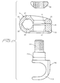
- the connector 14 and the nut 52 permit the surgeon to connect instead of the screw 12 a modular element 110 having at one end a hook part 113, as shown in Fig. 17.
- This modular element 110 is preferably an integral part of the system.
- the element 110 has at one end a thread portion 111 receiving the nut 52.
- a conical surface 112 touches the corresponding conical surface of opening 21.
Abstract
Description
- This invention relates to an apparatus according to the preamble of claim 1.
- Mechanisms are known whose aim is to stabilize the spine after surgical treatment of spinal problems. Many of these mechanisms included rods positioned parallel to the spine that carry pedicle screws via a connector. For instance, U.S. Patents 4,433,676 and 4,369,769 are illustrative. Also, the Howland patents 4,653,481 (issued 3/31/87) and 5,030,220 (issued 7/09/91) are directed to fixation methods. Howland recognized the advantages of using a rod or shaft about which a pedicle screw carrying member can slide near the area of a selected vertebrae. An elongated slot in the connector permits a further adjustment. EP 0 408 489 A discloses an apparatus for fixedly secure two vertebrae together corresponding to the preamble of claim 1. The apparatus comprises connector means, a spinal stabilizing rod and pedicle screw. The connector is comprised of two arms to grasp the smooth round rod. The pedicle screw is affixed in an opening of the connector and is pivotable about a pivot point having a fixed distance to the axis of the rod.
- In all spinal operations the skill of the surgeon is constantly challenged. The repair and reconstruction work that must be done is located close to vital nerve centers and each patient's spine is different in some respects.
- In order for the healing to take place, it is oftentimes required to fix one vertebrae with respect to an adjacent or remote vertebrae.
- The mechanism of this invention will fixedly secure two vertebrae together that are on either side of the injured portion of the spine. The vertebrae must be restrained from rotation or left to right, back to front, or up and down motions with respect to one another.
- The spine components are fixed in space with respect to one another until fusion occurs.
- The invention is defined in claim 1.
- A principle prefered objective of this invention is to provide a means by which pedicle screws can be readily adjusted and fixed along the length of a rod. It is essential that such longitudinal movement of the rod can be quickly accomplished with a mechanism that has few parts and which can be readily locked into position. This objective of this invention is met by providing a one-piece connector that has a jaw at one end thereof which can be quickly and efficiently tightened about a smooth rod.
- A still further prefered objective of this invention is to provide a connector or clamp to carry a pedicle screw along the rod for coarse positioning and having a means to permit a pivoting movement between the pedicle screw and the connector for fine adjustment while maintaining a fixed reference distance between the rod and the pedicle screw pivot point at all times.
- Another prefered objective of the invention is to provide a connector having two opposed arms having a bore therethrough that permits relative pivoting movement between the connector and the pedicle screw for a fine adjustment while maintaining a fixed distance between the pivot point of the pedicle screw and the spinal rod.
- A still further prefered objective of the invention is to provide a pedicle screw clamping member which can be snapped or placed on a smooth rod and is locked or clamped into position via a three area contact by the same members that secure the pedicle screw to the clamping member.
- Another principle prefered objective is to provide a clamping assembly that permits the location of the clamping jaws in various locations in the connector and still preserve the same pivoting ability.
- Another important prefered objective of the invention is to provide a unique washer assembly that permits the connector to pivot with respect to the pedicle screw after the latter is screwed to a vertebrae.
- The organization and operation of the invention described together with the objects and advantages thereof will be better understood from the following description considered in connection with the accompanying drawings in which the preferred embodiment of the invention is illustrated by way of example. It is to be expressly understood, however, that the drawings are for purposes of illustration and description only and not intended as the definition or limit of the invention.
- This invention relates to an improved support system for stabilizing the spine during and after surgical treatment of spinal problems which necessitates a fixation of the spinal components with respect to one another. The invention further relates to a system with an apparatus according to claim 1.
-
- Figure 1 is an exploded side elevation of several components of this invention;
- Figure 2 is a side view partially in section, of the components shown in Figure 1 in their assembled relationship;
- Figure 3 is a top plan view of a clamping snap-nut washer;
- Figure 4 is a cross-section view of a washer along the line 4-4 of Fig. 2;
- Figure 5 is a cross-section along the line 6-6 of Fig 1;
- Figure 6 is a top view of the member of Figure 5;
- Figure 7 is a top plan of second embodiment of a connector;
- Figure 8 is a side view of the member of Figure 7;
- Figure 9 is a cross-section along the lines 9-9 of Figure 8;
- Figure 10 is a top plan of a third clamping member;
- Figure 11 is a side view of the member of Figure 10;
- Figure 12 is a cross-section along the line 12-12 of Figure 11;
- Figure 13 and 14 are overall views showing the relationship of the apparatus with respect to the spinal cord;
- Figure 15 is a side view partially in section of a further embodiment of the apparatus according to the invention;
- Figure 16 illustrates the pivoting movement between the clamp and the screw; and
- Figure 17 is an exploded side elevation of a modular element and components of this invention.
-
- Referring now to the drawings wherein like numerals indicate like parts, the apparatus of this invention is generally indicated by the
numeral 10. Apedicle screw assembly 12 is carried by a clamp orconnector 14 which permits pivoting aboutpoint 15. When the invention is actually in use by the surgeon it is the connector that pivots. In Figure 2, the movement of the clamp with respect to the pedicle screw is shown. - The
pedicle screw assembly 12, from top to bottom (as viewed in Figs. 1 and 2), consists of a threadedportion 16; acurvilinear shoulder 17, ahexagonal nut 18, and a cancellousthread pedicle portion 20 for engagement with the vertebrae. Thepedicle screw assembly 12 is received byopenings shaped connector 14. These openings are normally coaxial and will sometimes be referred to collectively just asopenings 19. - The
connector 14 is comprised of anupper arm 22 and alower arm 23. Thearms arcuate hinge section 24 which is integral with thearms arms jaws rod 30. In the embodiment of Figs. 1 and 2, the jaws are formed near thehinged end 24. Alateral groove 25 is sometimes found inhinge section 24 to make thehinged end 24 more flexible. Theconnector 14 has itsco-axial openings arms pedicle screw assembly 12. Thecenter axis 32 of theopenings arms pedicle screw members 12 are screwed into the pedicle bone section of vertebrae above and below the damaged area. The stabilizingrod 30 extends there between. The components associated with a single pedicle screw are described herein. - A
washer 34 is slipped over the pedicle screw.Washer 34 has lower peripheralconvex surface 36 matching theconcave surface 17. The spinal stabilizingrod 30 has anaxis 30a perpendicular to thecenter axis 32 ofopenings space 25 is defined betweenarms rod 30 is permitted to slide longitudinally with respect to the pedicle screw assembly prior to tightening. Thepedicle screw portion 20 is threaded into the pedicle bone of a selected vertebrae. As will be seen hereinafter, the nuts and washers that secure thepedicle screw assembly 12 within theopenings connector 14 also move thearms rod 30. After therod 30 is located and secured to the screw assembly, the arms are drawn together. -
Arm 22 is formed with ajaw member 27 and thearm 23 is formed with ajaw member 29. When these jaws are located near the hinged end of theconnector 14 as seen in Fig. 1 and 2. - Once the
connector 14 is located correctly with respect to therod 30, the connector is permitted to pivot to permit the surgeon to position therod 30 correctly with respect to the pedicle screw. This relative adjustment can be seen best in Fig. 2. - As seen in Fig. 2, the
lower washer 34 is slipped over the upper end of theassembly 12 and is moved to a position where itscurved surface 36 rests against the uppercurved surface 17 adjacent thehexagonal nut 18. Thewasher 34 has a peripheral upperconcave surface 40. Thewasher 34 remains longitudinally stationary with respect to the pedicle screw. Asecond washer 42 is then slipped over thepedicle screw 12 until it engageswasher 34.Washer 42 has a bottomconvex surface 45 for engagement with theconcave surface 40. These surfaces can slide with respect to one another about a center point with the interengaging surfaces forming an arcuate segment of a circumference defined by R-25. - The
washer 42 can thus tilt and slide form side to side with respect to thelower washer 34. Thewasher 42 has acenter opening 48 that is an extension of theopenings arms -
Opening 19 inupper arm 22 of theconnector 14 is formed with an exterior concave counter bore 50. This annular depression or counter-bore 50 is formed at the upper end ofopening 19. The counter-bore 50 is adapted to receive a star-nut 52 having a lower matchingconvex surface 54 in sliding engagement with the concave counter bore 50. These surfaces slide along an arc of radius R-5. The perimeter of snap-nut washer 52 is formed withnotches screw section 16 of thepedicle screw 12 with its tines or prongs entering thenotches nut washer 52 is formed with a threaded opening 53 adapted to engage the threads ofpedicle screw section 16. - It should be noted that the
interior openings point 15 in all directions. The surfaces ofopenings arms - Operationally, the surgeon first threads the pedicle screws into the pedicle section of selected vertebrae. The
hexagon 18 is used for that purpose. There will be at least two pedicle screws secured to the pedicle bones of vertebrae above and below the damaged bone o disc. The surgeon will then sliprod 30 through the jaws and locate them so that the connector and washers are located as seen in Figure 2. When therod 30 is so positioned, the jaws are tightened. - The
pivotal pedical crew 12 has a fixed distance betweencenter axis 30a of therod 30 and thepivot point 15. However, relative pivoting movement between the elements is permitted so that the rod can be located in the desired position. Thestar nut 52 is then tightened alongthreads 12 until therod 30 is securely grasped. - In the clamp shown in Figs. 1 and 2, the clamping jaws are formed near the hinged
end 24 of the clamp rather than at the distal ends of the arms. - One example of a distal end clamp is shown in Figs. 7, 8 and 9. Here, the connector is indicated by the numeral 14a. The connector is formed by two
arms 22a and 23a having jaw members 34a and 36a formed at the distal ends thereof. The openings 19a and 21a are formed respectively in the upper andlower arms 22a and 23a between the jaw members and the hinged area 24a. The connector 14a is formed with a convex counter-bore 50 to receive the lower concave surface of a star-nut washer 52a, in the same manner as that shown in the previously described embodiment. The jaws 34a and 36a, of course, receive thespinal rod 30 in the same manner as the ring type connector previously described. Note that the lower jaw 36a is formed with anopening 80 formingbifurcated support extensions arcuate ridge 82 intermediate its length. Thisridge 82 and thesurfaces bifurcated extensions rod 30. - Another ring type connector is seen in Figs. 10, 11 and 12. The upper jaw 29b is equipped with an arcuate ridge 92b and an
opening 80 providessurfaces spinal rod 32. - As mentioned previously, one of the goals of this invention is to establish with certainty a fixed distance between the axis of the
spinal rod 30 and thepivot point 15. The systems herein described, however, permit a pivoting movement of the connector about screw assembly so that the surgeon can maneuver the rod to its most desirable location with respect to the spine and with respect to the previously secured pedicle screws. - The relative pivoting motion of the
connector 14 with respect to pedicle screw assembly is seen by the dotted lines of Figure 2. After the rod is properly located and the surgeon is satisfied with its location, the afore mentioned three-pronged tool is utilized to tighten thenut 52. This causes thearms connector 14 while maintaining the fixed distance between the pivotingpoint 15 and the center longitudinal axis of therod 32. - Figures 13 and 14 illustrate the relationship of the two
rods 30 with respect to a spine A. Therods 30 fixedly secure two vertebrae B and C together and restrain them from rotation and other motions with respect to one another. - Another embodiment of the apparatus is seen in Figs. 15 and 16. The
connector 100 has alower arm 106 which does not have a recess underneath but a lower andplanar surface 101 engaging aslip washer 102 with aconcave surface 105 facing away from theconnector 100. There is asecond slip washer 104 having a corresponding convex surface 103 touching theconcave surface 105 of theother washer 102. As Fig. 16 illustrates, thesurfaces 103 and 105 permit a pivoting movement between thepedical screw 12 and theconnector 100 for fine adjustment while maintaining a fixed distance between therod 30 and the pedicle screw. Biomechanical tests have proved that this embodiment was stronger in some applications and had more range of motion. - The
connector 14 and thenut 52 permit the surgeon to connect instead of the screw 12 amodular element 110 having at one end ahook part 113, as shown in Fig. 17. Thismodular element 110 is preferably an integral part of the system. Theelement 110 has at one end athread portion 111 receiving thenut 52. When tightening thenut 52, aconical surface 112 touches the corresponding conical surface ofopening 21. - Although the embodiments have been described with a certain degree of particularity, it is understood that the present disclosure has been made only by way of example and that changes in the details of construction and the combination and other arrangement of parts may be resorted to without departing from the scope of the claims. Thus, the scope of the invention should not be limited by the foregoing specification, but rather, by the scope of the claims appended hereto.
Claims (8)
- Apparatus for stabilizing certain vertebrae (B, C) of the spine (A) with respect to one another comprising:a spinal stabilizing rod (30) that is adapted to be placed in a generally parallel relationship with that portion of the spine (A) to be treated;a pedicle screw (12) having a bone cancellous type thread section (20) at one end and a machine thread section (16) at the other end thereof;a nut (18) between said sections;a first arm (22) having an opening (19) therethrough, a second arm (23) generally parallel to said first arm (22) and having a second opening (21) co-axial with said first opening, and a hinge coupling said arms (22, 23), said arms (22, 23) defining a space (25) there between;a connector (14) being formed by two arms hinged at one end of the arms; said openings (19, 21) having dimensions greater than the cross-section dimension of said pedicle screw (12) ;connector means (40, 42, 52) to affix said pedicle screw (12) in said opening about a pivot point (15) having a fixed distance to the axis of the spinal rod and permits said connector (14) to pivot with respect to said screw (12); characterised in that each of said connectors (14) include upper and lower arms (22, 23) having opposing jaws (34a, 36a) at one end and a hinge (24, 24a) at the other end and said connector (14) is formed of one piece of material and one of said jaws (36a) is formed with a pair of ridges (84, 86) and the other of said jaws (34a) is formed with a single ridge (82, 92b) so that said rod (30) has a three point suspension.
- The apparatus of claim 1 wherein first and second arms (22, 23) respectively carry first and second jaws (34a, 36a) to receive said rod.
- The apparatus of claim 2 wherein said upper arm (22) is counter-bored about said opening (19) and the surface of said connector bore having an arcuate surface,
a nut (52) threadedly received by said threaded section (16) and having a lower surface being a matching arcuate surface engaging said counter bore. - The apparatus of claim 3 where said nut (52) and said hexagonal nut (18) of said screw (12) can tighten said jaws (22a, 23a) about said rod (30) when said nut (52) is threaded toward said hexagonal nut (18).
- The apparatus of claim 1 wherein said rod (30) is adapted to receive two or more of said connectors (14).
- The apparatus of claim 1 wherein said single ridge (82, 92b) is located in a plane intermediate the planes of said pair of ridges (84, 86).
- The apparatus of claim 1 wherein said lower arm (106) has a lower surface (101) being a planar surface engaging a slip washer (102) with a concave surface (105) facing away from the connector (100).
- The apparatus of claim 7 wherein said slip washer (102) engages a second slip washer (104) having a convex surface (103) touching the concave surface (105) of the other washer (102).
Priority Applications (5)
| Application Number | Priority Date | Filing Date | Title |
|---|---|---|---|
| DE69721278T DE69721278T2 (en) | 1997-12-17 | 1997-12-17 | Apparatus for stabilizing certain vertebrae of the spine |
| AT97810998T ATE238003T1 (en) | 1997-12-17 | 1997-12-17 | APPARATUS FOR STABILIZING CERTAIN VERTEBRATES OF THE SPINE |
| ES97810998T ES2196290T3 (en) | 1997-12-17 | 1997-12-17 | APPARATUS TO STABILIZE CERTAIN VERTEBRAS OF THE DORSAL SPINE. |
| EP97810998A EP0923908B1 (en) | 1997-12-17 | 1997-12-17 | Apparatus for stabilizing certain vertebrae of the spine |
| US09/213,150 US6123706A (en) | 1997-12-17 | 1998-12-17 | Apparatus for stabilizing certain vertebrae of the spine |
Applications Claiming Priority (1)
| Application Number | Priority Date | Filing Date | Title |
|---|---|---|---|
| EP97810998A EP0923908B1 (en) | 1997-12-17 | 1997-12-17 | Apparatus for stabilizing certain vertebrae of the spine |
Publications (2)
| Publication Number | Publication Date |
|---|---|
| EP0923908A1 EP0923908A1 (en) | 1999-06-23 |
| EP0923908B1 true EP0923908B1 (en) | 2003-04-23 |
Family
ID=8230530
Family Applications (1)
| Application Number | Title | Priority Date | Filing Date |
|---|---|---|---|
| EP97810998A Expired - Lifetime EP0923908B1 (en) | 1997-12-17 | 1997-12-17 | Apparatus for stabilizing certain vertebrae of the spine |
Country Status (5)
| Country | Link |
|---|---|
| US (1) | US6123706A (en) |
| EP (1) | EP0923908B1 (en) |
| AT (1) | ATE238003T1 (en) |
| DE (1) | DE69721278T2 (en) |
| ES (1) | ES2196290T3 (en) |
Families Citing this family (128)
| Publication number | Priority date | Publication date | Assignee | Title |
|---|---|---|---|---|
| IES970411A2 (en) * | 1997-06-03 | 1997-12-03 | Tecos Holdings Inc | Pluridirectional and modulable vertebral osteosynthesis device of small overall size |
| WO1999055246A1 (en) | 1998-04-29 | 1999-11-04 | Dimso (Distribution Medicale Du Sud-Ouest) | Backbone osteosynthesis system for anterior fixing |
| FR2784282B1 (en) | 1998-10-09 | 2001-03-23 | Dimso Sa | SPINAL OSTEOSYNTHESIS SYSTEM WITH IMPROVED RIGIDITY |
| US6352537B1 (en) * | 1998-09-17 | 2002-03-05 | Electro-Biology, Inc. | Method and apparatus for spinal fixation |
| ES2156527B1 (en) * | 1999-01-20 | 2002-01-16 | Alacreu Jose Barbera | VERTEBRAL FIXING SYSTEM DORSO-LUMBAR AND LUMBO-SACRO. |
| DE19914232B4 (en) * | 1999-03-29 | 2012-08-30 | Signus Medizintechnik Gmbh | Device for stabilizing vertebral bodies of a spinal column |
| US6210413B1 (en) * | 1999-04-23 | 2001-04-03 | Sdgi Holdings, Inc. | Connecting apparatus using shape-memory technology |
| US6610062B2 (en) * | 2000-02-16 | 2003-08-26 | Ebi, L.P. | Method and system for spinal fixation |
| US6572618B1 (en) * | 2000-03-15 | 2003-06-03 | Sdgi Holdings, Inc. | Spinal implant connection assembly |
| US6562038B1 (en) * | 2000-03-15 | 2003-05-13 | Sdgi Holdings, Inc. | Spinal implant connection assembly |
| US6872209B2 (en) * | 2000-03-15 | 2005-03-29 | Sdgi Holdings, Inc. | Spinal implant connection assembly |
| WO2002002022A1 (en) | 2000-06-30 | 2002-01-10 | Stephen Ritland | Polyaxial connection device and method |
| ES2328108T3 (en) * | 2000-07-28 | 2009-11-10 | Synthes Gmbh | VERTEBRAL FIXING SYSTEM. |
| US7166073B2 (en) | 2000-09-29 | 2007-01-23 | Stephen Ritland | Method and device for microsurgical intermuscular spinal surgery |
| US6685705B1 (en) | 2000-10-23 | 2004-02-03 | Sdgi Holdings, Inc. | Six-axis and seven-axis adjustable connector |
| US6626906B1 (en) * | 2000-10-23 | 2003-09-30 | Sdgi Holdings, Inc. | Multi-planar adjustable connector |
| US7651516B2 (en) * | 2000-12-01 | 2010-01-26 | Spinevision S.A. | Connection assembly for the field of spinal osteosynthesis and method for using at least one such assembly |
| US6736852B2 (en) * | 2001-02-27 | 2004-05-18 | Incumed, Inc. | Adjustable bone prostheses and related methods |
| US6688798B2 (en) * | 2001-02-27 | 2004-02-10 | Incumed, Inc. | Adjustable locking mount and methods of use |
| US20070162140A1 (en) * | 2001-02-27 | 2007-07-12 | Mcdevitt Dennis M | Method and apparatus for reconstructing a joint |
| FR2823095B1 (en) | 2001-04-06 | 2004-02-06 | Ldr Medical | RACHIS OSTEOSYNTHESIS DEVICE AND PLACEMENT METHOD |
| EP1591072B1 (en) | 2001-04-24 | 2008-01-02 | coLigne AG | Instrumentation for stabilizing certain vertebrae of the spine |
| US6673074B2 (en) * | 2001-08-02 | 2004-01-06 | Endius Incorporated | Apparatus for retaining bone portions in a desired spatial relationship |
| US8021399B2 (en) | 2005-07-19 | 2011-09-20 | Stephen Ritland | Rod extension for extending fusion construct |
| US7722645B2 (en) * | 2001-09-24 | 2010-05-25 | Bryan Donald W | Pedicle screw spinal fixation device |
| US6574981B2 (en) * | 2001-09-24 | 2003-06-10 | Lancer Partnership, Ltd. | Beverage dispensing with cold carbonation |
| CA2460183C (en) | 2001-09-28 | 2011-04-12 | Stephen Ritland | Connection rod for screw or hook polyaxial system and method of use |
| FR2831049B1 (en) | 2001-10-18 | 2004-08-13 | Ldr Medical | PLATE FOR OSTEOSYNTHESIS DEVICE AND PRE-ASSEMBLY METHOD |
| FR2831048B1 (en) | 2001-10-18 | 2004-09-17 | Ldr Medical | PROGRESSIVE APPROACH OSTEOSYNTHESIS DEVICE AND PRE-ASSEMBLY PROCESS |
| FR2833151B1 (en) * | 2001-12-12 | 2004-09-17 | Ldr Medical | BONE ANCHORING IMPLANT WITH POLYAXIAL HEAD |
| WO2004065808A2 (en) * | 2002-01-08 | 2004-08-05 | Incumed Inc. | Adjustable locking mount and methods of use |
| AU2003239118B2 (en) | 2002-02-20 | 2007-09-20 | Stephen Ritland | Pedicle screw connector apparatus and method |
| US6966910B2 (en) | 2002-04-05 | 2005-11-22 | Stephen Ritland | Dynamic fixation device and method of use |
| WO2003094699A2 (en) | 2002-05-08 | 2003-11-20 | Stephen Ritland | Dynamic fixation device and method of use |
| US7306602B2 (en) * | 2002-10-31 | 2007-12-11 | Depuy Actomed, Inc. | Snap-in washers and assemblies thereof |
| US20040087952A1 (en) * | 2002-10-31 | 2004-05-06 | Amie Borgstrom | Universal polyaxial washer assemblies |
| GB0228575D0 (en) * | 2002-12-07 | 2003-01-15 | Depuy Int Ltd | A bone cement plug |
| US7104992B2 (en) * | 2003-01-14 | 2006-09-12 | Ebi, L.P. | Spinal fixation system |
| WO2004082522A2 (en) * | 2003-01-31 | 2004-09-30 | Murray Ian P | Multi-axial positioning system for a surgically-implanted spinal support |
| CA2516791C (en) * | 2003-02-25 | 2011-12-13 | Stephen Ritland | Adjustable rod and connector device and method of use |
| US20060293660A1 (en) * | 2005-06-03 | 2006-12-28 | Lewis Edward L | Connector for attaching an alignment rod to a bone structure |
| WO2004110247A2 (en) | 2003-05-22 | 2004-12-23 | Stephen Ritland | Intermuscular guide for retractor insertion and method of use |
| FR2856580B1 (en) * | 2003-06-27 | 2006-03-17 | Medicrea | MATERIAL OF VERTEBRAL OSTEOSYNTHESIS |
| FR2856581B1 (en) * | 2003-06-27 | 2005-08-19 | Medicrea | MATERIAL OF VERTEBRAL OSTEOSYNTHESIS |
| US8308772B2 (en) | 2003-06-27 | 2012-11-13 | Medicrea Technologies | Vertebral osteosynthesis equipment |
| FR2856579B1 (en) * | 2003-06-27 | 2006-03-17 | Medicrea | VERTEBRAL OSTEOSYNTHESIS EQUIPMENT AND METHOD FOR MANUFACTURING BONE ANCHORING MEMBER INCLUDING THESE MATERIALS |
| US7731734B2 (en) * | 2003-06-27 | 2010-06-08 | Medicrea Technologies | Vertebral osteosynthesis equipment |
| FR2859095B1 (en) | 2003-09-01 | 2006-05-12 | Ldr Medical | BONE ANCHORING IMPLANT WITH A POLYAXIAL HEAD AND METHOD OF PLACING THE IMPLANT |
| US7524191B2 (en) * | 2003-09-02 | 2009-04-28 | Rosetta Stone Ltd. | System and method for language instruction |
| FR2860138A1 (en) * | 2003-09-26 | 2005-04-01 | Stryker Spine | ASSEMBLY AND METHOD OF FIXING BONES |
| US7591837B2 (en) * | 2003-10-28 | 2009-09-22 | Pyramid Spine, Llc | Facet triangle spinal fixation device and method of use |
| US7261715B2 (en) * | 2003-11-24 | 2007-08-28 | Sdgi Holdings, Inc. | Grommet assembly |
| US7806914B2 (en) * | 2003-12-31 | 2010-10-05 | Spine Wave, Inc. | Dynamic spinal stabilization system |
| US20050143737A1 (en) * | 2003-12-31 | 2005-06-30 | John Pafford | Dynamic spinal stabilization system |
| US7678137B2 (en) | 2004-01-13 | 2010-03-16 | Life Spine, Inc. | Pedicle screw constructs for spine fixation systems |
| FR2865373B1 (en) * | 2004-01-27 | 2006-03-03 | Medicrea International | MATERIAL OF VERTEBRAL OSTEOSYNTHESIS |
| US7993373B2 (en) * | 2005-02-22 | 2011-08-09 | Hoy Robert W | Polyaxial orthopedic fastening apparatus |
| US8900270B2 (en) * | 2004-02-17 | 2014-12-02 | Gmedelaware 2 Llc | Facet joint replacement instruments and methods |
| DE102004010380A1 (en) * | 2004-03-03 | 2005-09-22 | Biedermann Motech Gmbh | Anchoring element and stabilizing device for the dynamic stabilization of vertebrae or bones with such an anchoring element |
| US7938848B2 (en) | 2004-06-09 | 2011-05-10 | Life Spine, Inc. | Spinal fixation system |
| US7744635B2 (en) * | 2004-06-09 | 2010-06-29 | Spinal Generations, Llc | Spinal fixation system |
| US8021398B2 (en) * | 2004-06-09 | 2011-09-20 | Life Spine, Inc. | Spinal fixation system |
| US8114158B2 (en) | 2004-08-03 | 2012-02-14 | Kspine, Inc. | Facet device and method |
| US20060058787A1 (en) * | 2004-08-24 | 2006-03-16 | Stryker Spine | Spinal implant assembly |
| WO2006058221A2 (en) | 2004-11-24 | 2006-06-01 | Abdou Samy M | Devices and methods for inter-vertebral orthopedic device placement |
| US7578833B2 (en) * | 2004-12-13 | 2009-08-25 | Dr. Robert S. Bray, Jr. | Bone fastener assembly for bone retention apparatus |
| US7736380B2 (en) | 2004-12-21 | 2010-06-15 | Rhausler, Inc. | Cervical plate system |
| ES2275382B1 (en) * | 2005-01-03 | 2008-06-01 | Socinser 21, S.A. | TRANSPEDICULAR VERTEBRAL FIXING SYSTEM. |
| US7678112B2 (en) * | 2005-04-26 | 2010-03-16 | Warsaw Orthopedic, Inc. | Open dorsal adjusting connector |
| US7780706B2 (en) | 2005-04-27 | 2010-08-24 | Trinity Orthopedics, Llc | Mono-planar pedicle screw method, system and kit |
| US20070161990A1 (en) * | 2005-12-21 | 2007-07-12 | Zimmer Spine, Inc. | Spinal implant hooks and systems |
| EP1971282A2 (en) * | 2006-01-10 | 2008-09-24 | Life Spine, Inc. | Pedicle screw constructs and spinal rod attachment assemblies |
| US7959564B2 (en) | 2006-07-08 | 2011-06-14 | Stephen Ritland | Pedicle seeker and retractor, and methods of use |
| US8388660B1 (en) | 2006-08-01 | 2013-03-05 | Samy Abdou | Devices and methods for superior fixation of orthopedic devices onto the vertebral column |
| JP4221032B2 (en) * | 2007-02-14 | 2009-02-12 | 昭和医科工業株式会社 | connector |
| JP4221033B2 (en) * | 2007-02-14 | 2009-02-12 | 昭和医科工業株式会社 | Vertebral connecting member and nut driver |
| WO2008140756A2 (en) * | 2007-05-09 | 2008-11-20 | Vertiflex, Inc. | Systems and methods for posterior dynamic stabilization of the spine |
| US8162987B2 (en) | 2007-06-05 | 2012-04-24 | Spartek Medical, Inc. | Modular spine treatment kit for dynamic stabilization and motion preservation of the spine |
| US8298267B2 (en) | 2007-06-05 | 2012-10-30 | Spartek Medical, Inc. | Spine implant with a deflection rod system including a deflection limiting shield associated with a bone screw and method |
| US8048115B2 (en) | 2007-06-05 | 2011-11-01 | Spartek Medical, Inc. | Surgical tool and method for implantation of a dynamic bone anchor |
| WO2008154313A1 (en) | 2007-06-06 | 2008-12-18 | Vertech, Inc. | Medical device and method to correct deformity |
| US8056874B2 (en) * | 2007-06-08 | 2011-11-15 | Blue Sky Designs, Inc. | Mounting and positioning apparatus for increased user independence |
| FR2916956B1 (en) | 2007-06-08 | 2012-12-14 | Ldr Medical | INTERSOMATIC CAGE, INTERVERTEBRAL PROSTHESIS, ANCHORING DEVICE AND IMPLANTATION INSTRUMENTATION |
| US20090062822A1 (en) * | 2007-08-31 | 2009-03-05 | Frasier William J | Adaptable clamping mechanism for coupling a spinal fixation element to a bone anchor |
| US8057517B2 (en) | 2008-02-26 | 2011-11-15 | Spartek Medical, Inc. | Load-sharing component having a deflectable post and centering spring and method for dynamic stabilization of the spine |
| US8267979B2 (en) | 2008-02-26 | 2012-09-18 | Spartek Medical, Inc. | Load-sharing bone anchor having a deflectable post and axial spring and method for dynamic stabilization of the spine |
| US8083775B2 (en) | 2008-02-26 | 2011-12-27 | Spartek Medical, Inc. | Load-sharing bone anchor having a natural center of rotation and method for dynamic stabilization of the spine |
| US20100030224A1 (en) | 2008-02-26 | 2010-02-04 | Spartek Medical, Inc. | Surgical tool and method for connecting a dynamic bone anchor and dynamic vertical rod |
| US8016861B2 (en) * | 2008-02-26 | 2011-09-13 | Spartek Medical, Inc. | Versatile polyaxial connector assembly and method for dynamic stabilization of the spine |
| US9060813B1 (en) | 2008-02-29 | 2015-06-23 | Nuvasive, Inc. | Surgical fixation system and related methods |
| US8221473B2 (en) * | 2008-03-13 | 2012-07-17 | Life Spine, Inc. | Spinal rod connector assembly for a vertebral bone screw |
| US8828058B2 (en) | 2008-11-11 | 2014-09-09 | Kspine, Inc. | Growth directed vertebral fixation system with distractible connector(s) and apical control |
| US8597332B2 (en) * | 2009-02-19 | 2013-12-03 | Ulrich Gmbh & Co. Kg | Apparatus for spinal-column stabilization |
| MX2009013313A (en) * | 2009-02-19 | 2010-09-27 | Ulrich Gmbh & Co Kg | Device for stabilizing the spinal column. |
| US8357182B2 (en) | 2009-03-26 | 2013-01-22 | Kspine, Inc. | Alignment system with longitudinal support features |
| US8876869B1 (en) | 2009-06-19 | 2014-11-04 | Nuvasive, Inc. | Polyaxial bone screw assembly |
| US8506598B1 (en) | 2009-06-26 | 2013-08-13 | Nuvasive, Inc. | Anchors for spinal fixation and correcting spinal deformity |
| US9168071B2 (en) | 2009-09-15 | 2015-10-27 | K2M, Inc. | Growth modulation system |
| EP2506785A4 (en) | 2009-12-02 | 2014-10-15 | Spartek Medical Inc | Low profile spinal prosthesis incorporating a bone anchor having a deflectable post and a compound spinal rod |
| US8764806B2 (en) | 2009-12-07 | 2014-07-01 | Samy Abdou | Devices and methods for minimally invasive spinal stabilization and instrumentation |
| US20110307018A1 (en) | 2010-06-10 | 2011-12-15 | Spartek Medical, Inc. | Adaptive spinal rod and methods for stabilization of the spine |
| US9198692B1 (en) | 2011-02-10 | 2015-12-01 | Nuvasive, Inc. | Spinal fixation anchor |
| US9186184B2 (en) * | 2011-02-14 | 2015-11-17 | Pioneer Surgical Technology, Inc. | Spinal fixation system and method |
| US9387013B1 (en) | 2011-03-01 | 2016-07-12 | Nuvasive, Inc. | Posterior cervical fixation system |
| US8992579B1 (en) * | 2011-03-08 | 2015-03-31 | Nuvasive, Inc. | Lateral fixation constructs and related methods |
| CN103781429B (en) | 2011-06-03 | 2017-02-15 | 科斯班公司 | Spinal correction system actuators |
| US9005249B2 (en) | 2011-07-11 | 2015-04-14 | Life Spine, Inc. | Spinal rod connector assembly |
| US8845728B1 (en) | 2011-09-23 | 2014-09-30 | Samy Abdou | Spinal fixation devices and methods of use |
| US9468468B2 (en) | 2011-11-16 | 2016-10-18 | K2M, Inc. | Transverse connector for spinal stabilization system |
| US8920472B2 (en) | 2011-11-16 | 2014-12-30 | Kspine, Inc. | Spinal correction and secondary stabilization |
| US9468469B2 (en) | 2011-11-16 | 2016-10-18 | K2M, Inc. | Transverse coupler adjuster spinal correction systems and methods |
| WO2014172632A2 (en) | 2011-11-16 | 2014-10-23 | Kspine, Inc. | Spinal correction and secondary stabilization |
| US9451987B2 (en) | 2011-11-16 | 2016-09-27 | K2M, Inc. | System and method for spinal correction |
| US8430916B1 (en) | 2012-02-07 | 2013-04-30 | Spartek Medical, Inc. | Spinal rod connectors, methods of use, and spinal prosthesis incorporating spinal rod connectors |
| US20130226240A1 (en) | 2012-02-22 | 2013-08-29 | Samy Abdou | Spinous process fixation devices and methods of use |
| US9060815B1 (en) | 2012-03-08 | 2015-06-23 | Nuvasive, Inc. | Systems and methods for performing spine surgery |
| US9198767B2 (en) | 2012-08-28 | 2015-12-01 | Samy Abdou | Devices and methods for spinal stabilization and instrumentation |
| US9320617B2 (en) | 2012-10-22 | 2016-04-26 | Cogent Spine, LLC | Devices and methods for spinal stabilization and instrumentation |
| US9743959B2 (en) | 2013-03-14 | 2017-08-29 | Atlas Spine, Inc. | Low profile spinal fixation system |
| WO2015029042A1 (en) | 2013-09-01 | 2015-03-05 | Carbofix Orthopedics Ltd. | Composite material spinal implant |
| WO2016035010A1 (en) * | 2014-09-01 | 2016-03-10 | Carbofix In Orthopedics Llc | Composite material spinal implant |
| US9468471B2 (en) | 2013-09-17 | 2016-10-18 | K2M, Inc. | Transverse coupler adjuster spinal correction systems and methods |
| US9517089B1 (en) | 2013-10-08 | 2016-12-13 | Nuvasive, Inc. | Bone anchor with offset rod connector |
| US10285637B1 (en) * | 2014-11-10 | 2019-05-14 | University Of Louisville Research Foundation, Inc. | Apparatus for sensing strain on a spinal fusion rod |
| US10857003B1 (en) | 2015-10-14 | 2020-12-08 | Samy Abdou | Devices and methods for vertebral stabilization |
| US10973648B1 (en) | 2016-10-25 | 2021-04-13 | Samy Abdou | Devices and methods for vertebral bone realignment |
| US10744000B1 (en) | 2016-10-25 | 2020-08-18 | Samy Abdou | Devices and methods for vertebral bone realignment |
| US11179248B2 (en) | 2018-10-02 | 2021-11-23 | Samy Abdou | Devices and methods for spinal implantation |
Family Cites Families (12)
| Publication number | Priority date | Publication date | Assignee | Title |
|---|---|---|---|---|
| US4369769A (en) | 1980-06-13 | 1983-01-25 | Edwards Charles C | Spinal fixation device and method |
| CA1158402A (en) | 1981-04-06 | 1983-12-13 | Kevin A. Bobechko | Self-adjusting spinal scoliosis fusion hook |
| US4653481A (en) | 1985-07-24 | 1987-03-31 | Howland Robert S | Advanced spine fixation system and method |
| US5024213A (en) * | 1989-02-08 | 1991-06-18 | Acromed Corporation | Connector for a corrective device |
| CH678803A5 (en) * | 1989-07-12 | 1991-11-15 | Sulzer Ag | |
| US5030220A (en) | 1990-03-29 | 1991-07-09 | Advanced Spine Fixation Systems Incorporated | Spine fixation system |
| FR2702361B1 (en) * | 1993-02-24 | 1997-10-24 | Soprane Sa | Fixator for lumbosacral osteosyntheses. |
| FR2720923B1 (en) * | 1994-06-10 | 1997-04-18 | Sra Sarl | Screw for osteosynthesis. |
| FR2730155B3 (en) * | 1995-02-03 | 1997-04-18 | Alby Albert | IMPLANT FOR SPINE OSTEOSYNTHESIS DEVICE |
| FR2731344B1 (en) * | 1995-03-06 | 1997-08-22 | Dimso Sa | SPINAL INSTRUMENTATION ESPECIALLY FOR A ROD |
| DE19512709A1 (en) * | 1995-04-08 | 1996-10-10 | Rehder Guenther | Holding device for prosthesis |
| US5613968A (en) * | 1995-05-01 | 1997-03-25 | Lin; Chih-I | Universal pad fixation device for orthopedic surgery |
-
1997
- 1997-12-17 EP EP97810998A patent/EP0923908B1/en not_active Expired - Lifetime
- 1997-12-17 DE DE69721278T patent/DE69721278T2/en not_active Expired - Lifetime
- 1997-12-17 AT AT97810998T patent/ATE238003T1/en not_active IP Right Cessation
- 1997-12-17 ES ES97810998T patent/ES2196290T3/en not_active Expired - Lifetime
-
1998
- 1998-12-17 US US09/213,150 patent/US6123706A/en not_active Expired - Fee Related
Also Published As
| Publication number | Publication date |
|---|---|
| DE69721278T2 (en) | 2004-02-05 |
| EP0923908A1 (en) | 1999-06-23 |
| DE69721278D1 (en) | 2003-05-28 |
| ATE238003T1 (en) | 2003-05-15 |
| ES2196290T3 (en) | 2003-12-16 |
| US6123706A (en) | 2000-09-26 |
Similar Documents
| Publication | Publication Date | Title |
|---|---|---|
| EP0923908B1 (en) | Apparatus for stabilizing certain vertebrae of the spine | |
| US6786907B2 (en) | Instrumentation for stabilizing certain vertebrae of the spine | |
| EP0425783B1 (en) | Pedicle screw clamp | |
| AU704134B2 (en) | Spine construct with band clamp | |
| US6083154A (en) | Surgical instrumentation and method for retracting and shifting tissues | |
| US8721689B2 (en) | Multi-axial spinal cross-connectors | |
| US5190543A (en) | Anchoring device | |
| US5976135A (en) | Lateral connector assembly | |
| US10993746B2 (en) | Head to head transverse connector | |
| US5267999A (en) | Clamp for use in spinal surgery | |
| US6030388A (en) | Top tightening bone fixation apparatus | |
| US8241334B2 (en) | Spinal cross-connector | |
| US7794464B2 (en) | Spinal derotation instruments and methods | |
| AU762937B2 (en) | Backbone osteosynthesis system for anterior fixing | |
| US6409729B1 (en) | Clamp assembly for an external fixation system | |
| EP1281362B1 (en) | Implant for bone connector | |
| US7744634B2 (en) | Spinal rod system | |
| US5397363A (en) | Spinal stabilization implant system | |
| US5047029A (en) | Clamp and system for internal fixation | |
| EP1093761B1 (en) | Spinal cross connector | |
| US9439679B2 (en) | Bone fixation system | |
| EP0499037A2 (en) | Spinal fixator reduction frame | |
| CA2208054A1 (en) | External fixator for distal radius fractures | |
| JPH0548698B2 (en) | ||
| JP2004524877A (en) | Device for fixing rod and spherically symmetric screw head |
Legal Events
| Date | Code | Title | Description |
|---|---|---|---|
| PUAI | Public reference made under article 153(3) epc to a published international application that has entered the european phase |
Free format text: ORIGINAL CODE: 0009012 |
|
| AK | Designated contracting states |
Kind code of ref document: A1 Designated state(s): AT BE CH DE DK ES FI FR GB GR IE IT LI NL PT SE |
|
| AX | Request for extension of the european patent |
Free format text: AL;LT;LV;MK;RO;SI |
|
| 17P | Request for examination filed |
Effective date: 19991223 |
|
| AKX | Designation fees paid |
Free format text: AT BE CH DE DK ES FI FR GB GR IE IT LI NL PT SE |
|
| 17Q | First examination report despatched |
Effective date: 20010313 |
|
| GRAG | Despatch of communication of intention to grant |
Free format text: ORIGINAL CODE: EPIDOS AGRA |
|
| GRAG | Despatch of communication of intention to grant |
Free format text: ORIGINAL CODE: EPIDOS AGRA |
|
| GRAH | Despatch of communication of intention to grant a patent |
Free format text: ORIGINAL CODE: EPIDOS IGRA |
|
| GRAH | Despatch of communication of intention to grant a patent |
Free format text: ORIGINAL CODE: EPIDOS IGRA |
|
| GRAA | (expected) grant |
Free format text: ORIGINAL CODE: 0009210 |
|
| AK | Designated contracting states |
Designated state(s): AT BE CH DE DK ES FI FR GB GR IE IT LI NL PT SE |
|
| PG25 | Lapsed in a contracting state [announced via postgrant information from national office to epo] |
Ref country code: FI Free format text: LAPSE BECAUSE OF FAILURE TO SUBMIT A TRANSLATION OF THE DESCRIPTION OR TO PAY THE FEE WITHIN THE PRESCRIBED TIME-LIMIT Effective date: 20030423 Ref country code: AT Free format text: LAPSE BECAUSE OF FAILURE TO SUBMIT A TRANSLATION OF THE DESCRIPTION OR TO PAY THE FEE WITHIN THE PRESCRIBED TIME-LIMIT Effective date: 20030423 |
|
| REG | Reference to a national code |
Ref country code: GB Ref legal event code: FG4D |
|
| REG | Reference to a national code |
Ref country code: CH Ref legal event code: NV Representative=s name: ISLER & PEDRAZZINI AG Ref country code: CH Ref legal event code: EP |
|
| REF | Corresponds to: |
Ref document number: 69721278 Country of ref document: DE Date of ref document: 20030528 Kind code of ref document: P |
|
| REG | Reference to a national code |
Ref country code: IE Ref legal event code: FG4D |
|
| PG25 | Lapsed in a contracting state [announced via postgrant information from national office to epo] |
Ref country code: SE Free format text: LAPSE BECAUSE OF FAILURE TO SUBMIT A TRANSLATION OF THE DESCRIPTION OR TO PAY THE FEE WITHIN THE PRESCRIBED TIME-LIMIT Effective date: 20030723 Ref country code: PT Free format text: LAPSE BECAUSE OF FAILURE TO SUBMIT A TRANSLATION OF THE DESCRIPTION OR TO PAY THE FEE WITHIN THE PRESCRIBED TIME-LIMIT Effective date: 20030723 Ref country code: GR Free format text: LAPSE BECAUSE OF FAILURE TO SUBMIT A TRANSLATION OF THE DESCRIPTION OR TO PAY THE FEE WITHIN THE PRESCRIBED TIME-LIMIT Effective date: 20030723 Ref country code: DK Free format text: LAPSE BECAUSE OF FAILURE TO SUBMIT A TRANSLATION OF THE DESCRIPTION OR TO PAY THE FEE WITHIN THE PRESCRIBED TIME-LIMIT Effective date: 20030723 |
|
| ET | Fr: translation filed | ||
| REG | Reference to a national code |
Ref country code: ES Ref legal event code: FG2A Ref document number: 2196290 Country of ref document: ES Kind code of ref document: T3 |
|
| PG25 | Lapsed in a contracting state [announced via postgrant information from national office to epo] |
Ref country code: IE Free format text: LAPSE BECAUSE OF NON-PAYMENT OF DUE FEES Effective date: 20031217 |
|
| PLBE | No opposition filed within time limit |
Free format text: ORIGINAL CODE: 0009261 |
|
| STAA | Information on the status of an ep patent application or granted ep patent |
Free format text: STATUS: NO OPPOSITION FILED WITHIN TIME LIMIT |
|
| 26N | No opposition filed |
Effective date: 20040126 |
|
| REG | Reference to a national code |
Ref country code: IE Ref legal event code: MM4A |
|
| REG | Reference to a national code |
Ref country code: CH Ref legal event code: PCAR Free format text: ISLER & PEDRAZZINI AG;POSTFACH 1772;8027 ZUERICH (CH) |
|
| PGFP | Annual fee paid to national office [announced via postgrant information from national office to epo] |
Ref country code: NL Payment date: 20080630 Year of fee payment: 11 Ref country code: ES Payment date: 20080703 Year of fee payment: 11 |
|
| PGFP | Annual fee paid to national office [announced via postgrant information from national office to epo] |
Ref country code: IT Payment date: 20080630 Year of fee payment: 11 |
|
| NLV4 | Nl: lapsed or anulled due to non-payment of the annual fee |
Effective date: 20090701 |
|
| PG25 | Lapsed in a contracting state [announced via postgrant information from national office to epo] |
Ref country code: NL Free format text: LAPSE BECAUSE OF NON-PAYMENT OF DUE FEES Effective date: 20090701 |
|
| REG | Reference to a national code |
Ref country code: ES Ref legal event code: FD2A Effective date: 20081218 |
|
| PG25 | Lapsed in a contracting state [announced via postgrant information from national office to epo] |
Ref country code: ES Free format text: LAPSE BECAUSE OF NON-PAYMENT OF DUE FEES Effective date: 20081218 |
|
| PGFP | Annual fee paid to national office [announced via postgrant information from national office to epo] |
Ref country code: FR Payment date: 20110104 Year of fee payment: 14 |
|
| PGFP | Annual fee paid to national office [announced via postgrant information from national office to epo] |
Ref country code: CH Payment date: 20101124 Year of fee payment: 14 |
|
| PGFP | Annual fee paid to national office [announced via postgrant information from national office to epo] |
Ref country code: GB Payment date: 20101221 Year of fee payment: 14 |
|
| PGFP | Annual fee paid to national office [announced via postgrant information from national office to epo] |
Ref country code: DE Payment date: 20101222 Year of fee payment: 14 |
|
| PGFP | Annual fee paid to national office [announced via postgrant information from national office to epo] |
Ref country code: BE Payment date: 20110124 Year of fee payment: 14 |
|
| BERE | Be: lapsed |
Owner name: *LANGE ROBERT Effective date: 20111231 |
|
| REG | Reference to a national code |
Ref country code: CH Ref legal event code: PL |
|
| GBPC | Gb: european patent ceased through non-payment of renewal fee |
Effective date: 20111217 |
|
| REG | Reference to a national code |
Ref country code: FR Ref legal event code: ST Effective date: 20120831 |
|
| REG | Reference to a national code |
Ref country code: DE Ref legal event code: R119 Ref document number: 69721278 Country of ref document: DE Effective date: 20120703 |
|
| PG25 | Lapsed in a contracting state [announced via postgrant information from national office to epo] |
Ref country code: DE Free format text: LAPSE BECAUSE OF NON-PAYMENT OF DUE FEES Effective date: 20120703 Ref country code: LI Free format text: LAPSE BECAUSE OF NON-PAYMENT OF DUE FEES Effective date: 20111231 Ref country code: BE Free format text: LAPSE BECAUSE OF NON-PAYMENT OF DUE FEES Effective date: 20111231 Ref country code: GB Free format text: LAPSE BECAUSE OF NON-PAYMENT OF DUE FEES Effective date: 20111217 Ref country code: CH Free format text: LAPSE BECAUSE OF NON-PAYMENT OF DUE FEES Effective date: 20111231 |
|
| PG25 | Lapsed in a contracting state [announced via postgrant information from national office to epo] |
Ref country code: FR Free format text: LAPSE BECAUSE OF NON-PAYMENT OF DUE FEES Effective date: 20120102 |
|
| PG25 | Lapsed in a contracting state [announced via postgrant information from national office to epo] |
Ref country code: IT Free format text: LAPSE BECAUSE OF NON-PAYMENT OF DUE FEES Effective date: 20081217 |