EP1413820A2 - Camera lens module rotatable around two axes - Google Patents
Camera lens module rotatable around two axes Download PDFInfo
- Publication number
- EP1413820A2 EP1413820A2 EP20030023982 EP03023982A EP1413820A2 EP 1413820 A2 EP1413820 A2 EP 1413820A2 EP 20030023982 EP20030023982 EP 20030023982 EP 03023982 A EP03023982 A EP 03023982A EP 1413820 A2 EP1413820 A2 EP 1413820A2
- Authority
- EP
- European Patent Office
- Prior art keywords
- pivot axis
- camera lens
- lens module
- lens
- rotating
- Prior art date
- Legal status (The legal status is an assumption and is not a legal conclusion. Google has not performed a legal analysis and makes no representation as to the accuracy of the status listed.)
- Withdrawn
Links
- 230000001131 transforming effect Effects 0.000 claims abstract 4
- 210000000707 wrist Anatomy 0.000 description 3
- 239000004973 liquid crystal related substance Substances 0.000 description 2
Images


Classifications
-
- F—MECHANICAL ENGINEERING; LIGHTING; HEATING; WEAPONS; BLASTING
- F16—ENGINEERING ELEMENTS AND UNITS; GENERAL MEASURES FOR PRODUCING AND MAINTAINING EFFECTIVE FUNCTIONING OF MACHINES OR INSTALLATIONS; THERMAL INSULATION IN GENERAL
- F16M—FRAMES, CASINGS OR BEDS OF ENGINES, MACHINES OR APPARATUS, NOT SPECIFIC TO ENGINES, MACHINES OR APPARATUS PROVIDED FOR ELSEWHERE; STANDS; SUPPORTS
- F16M13/00—Other supports for positioning apparatus or articles; Means for steadying hand-held apparatus or articles
- F16M13/005—Other supports for positioning apparatus or articles; Means for steadying hand-held apparatus or articles integral with the apparatus or articles to be supported
-
- H—ELECTRICITY
- H04—ELECTRIC COMMUNICATION TECHNIQUE
- H04B—TRANSMISSION
- H04B1/00—Details of transmission systems, not covered by a single one of groups H04B3/00 - H04B13/00; Details of transmission systems not characterised by the medium used for transmission
- H04B1/38—Transceivers, i.e. devices in which transmitter and receiver form a structural unit and in which at least one part is used for functions of transmitting and receiving
- H04B1/40—Circuits
-
- F—MECHANICAL ENGINEERING; LIGHTING; HEATING; WEAPONS; BLASTING
- F16—ENGINEERING ELEMENTS AND UNITS; GENERAL MEASURES FOR PRODUCING AND MAINTAINING EFFECTIVE FUNCTIONING OF MACHINES OR INSTALLATIONS; THERMAL INSULATION IN GENERAL
- F16M—FRAMES, CASINGS OR BEDS OF ENGINES, MACHINES OR APPARATUS, NOT SPECIFIC TO ENGINES, MACHINES OR APPARATUS PROVIDED FOR ELSEWHERE; STANDS; SUPPORTS
- F16M11/00—Stands or trestles as supports for apparatus or articles placed thereon ; Stands for scientific apparatus such as gravitational force meters
- F16M11/02—Heads
- F16M11/04—Means for attachment of apparatus; Means allowing adjustment of the apparatus relatively to the stand
- F16M11/06—Means for attachment of apparatus; Means allowing adjustment of the apparatus relatively to the stand allowing pivoting
- F16M11/12—Means for attachment of apparatus; Means allowing adjustment of the apparatus relatively to the stand allowing pivoting in more than one direction
- F16M11/126—Means for attachment of apparatus; Means allowing adjustment of the apparatus relatively to the stand allowing pivoting in more than one direction for tilting and panning
-
- F—MECHANICAL ENGINEERING; LIGHTING; HEATING; WEAPONS; BLASTING
- F16—ENGINEERING ELEMENTS AND UNITS; GENERAL MEASURES FOR PRODUCING AND MAINTAINING EFFECTIVE FUNCTIONING OF MACHINES OR INSTALLATIONS; THERMAL INSULATION IN GENERAL
- F16M—FRAMES, CASINGS OR BEDS OF ENGINES, MACHINES OR APPARATUS, NOT SPECIFIC TO ENGINES, MACHINES OR APPARATUS PROVIDED FOR ELSEWHERE; STANDS; SUPPORTS
- F16M11/00—Stands or trestles as supports for apparatus or articles placed thereon ; Stands for scientific apparatus such as gravitational force meters
- F16M11/02—Heads
- F16M11/18—Heads with mechanism for moving the apparatus relatively to the stand
-
- G—PHYSICS
- G02—OPTICS
- G02B—OPTICAL ELEMENTS, SYSTEMS OR APPARATUS
- G02B7/00—Mountings, adjusting means, or light-tight connections, for optical elements
- G02B7/02—Mountings, adjusting means, or light-tight connections, for optical elements for lenses
- G02B7/023—Mountings, adjusting means, or light-tight connections, for optical elements for lenses permitting adjustment
-
- H—ELECTRICITY
- H04—ELECTRIC COMMUNICATION TECHNIQUE
- H04M—TELEPHONIC COMMUNICATION
- H04M1/00—Substation equipment, e.g. for use by subscribers
- H04M1/02—Constructional features of telephone sets
- H04M1/0202—Portable telephone sets, e.g. cordless phones, mobile phones or bar type handsets
- H04M1/026—Details of the structure or mounting of specific components
- H04M1/0264—Details of the structure or mounting of specific components for a camera module assembly
-
- H—ELECTRICITY
- H04—ELECTRIC COMMUNICATION TECHNIQUE
- H04N—PICTORIAL COMMUNICATION, e.g. TELEVISION
- H04N23/00—Cameras or camera modules comprising electronic image sensors; Control thereof
- H04N23/50—Constructional details
- H04N23/55—Optical parts specially adapted for electronic image sensors; Mounting thereof
-
- H—ELECTRICITY
- H04—ELECTRIC COMMUNICATION TECHNIQUE
- H04M—TELEPHONIC COMMUNICATION
- H04M1/00—Substation equipment, e.g. for use by subscribers
- H04M1/02—Constructional features of telephone sets
- H04M1/0202—Portable telephone sets, e.g. cordless phones, mobile phones or bar type handsets
- H04M1/0206—Portable telephones comprising a plurality of mechanically joined movable body parts, e.g. hinged housings
- H04M1/0208—Portable telephones comprising a plurality of mechanically joined movable body parts, e.g. hinged housings characterized by the relative motions of the body parts
- H04M1/0214—Foldable telephones, i.e. with body parts pivoting to an open position around an axis parallel to the plane they define in closed position
Definitions
- the present invention relates to a camera lens module for a portable terminal capable of performing video conversation or communication, or for photographing a desired object, and more particularly to a camera lens module capable of rotating in two axial directions, i.e. in vertical and horizontal directions.
- a "portable terminal” means a lightweight, small, portable device that it is capable of providing telecommunication services to a user who is either stationary or in motion so as to perform wireless communication with a corresponding partner. Such wireless communication may be voice, image, or Internet communication.
- the portable terminals are classified into various types, for example, a bar type, flip type or folder type, based on its geometry.
- the bar type portable terminal constitutes a single housing which takes a bar shape.
- the folder type portable terminal has a folder is pivotably coupled to a single bar-shaped housing by a hinge so as to make the terminal foldable.
- the portable terminal may be classified into a neck wearable type or a wrist wearable type based on a use position or the way in which the user puts it on.
- the neck wearable type portable terminal is worn around the user's neck using a string, while the wrist wearable type portable terminalis worn around the user's wrist.
- the portable terminal may be classified into a rotation type or a sliding type based on the manner in which the terminal is opened or closed.
- the rotation type portable terminal has two housings coupled to each other in such a manner that one housing is capable of being rotatably opened or closed with respect to the other.
- the sliding type portable terminal has two housings coupled to each other in such a manner that one housing is capable of being slidably opened or closed with respect to the other along in a longitudinal direction.
- the data input unit typically employs a key pad with a plurality of keys, by which data is input by pushing a key down with at least one finger. This may also be true for a touch pad or a touch screen.
- the data output unit generally makes use of a liquid crystal display (LCD).
- the key pad for inputting data consists of an array of a plurality of keys. These keys include numeral keys, character keys, sending keys, end key, functional keys, and so forth.
- the keys typically ranging in number from 15 to 20, are generally placed on the top surface of the housing of the portable terminal. The keys are exposed on the top surface the portable terminal so that the user can push them with at least one finger to input desired data.
- a camera lens module is mounted on a main housing of the potable terminal.
- a camera lens module is mounted in a rotatable fashion rather than in a fixed fashion at a predetermined position of the main housing so that the user can conveniently operate the camera lens module.
- a housing of the camera lens module is provided with a rotatable dial which is rotatably coupled to the housing.
- the camera lens module is generally designed to be rotatable in one direction. Therefore, the user meets with inconvenienced when performing video conversation or communication, or when photographing a desired object. That is to say, because the conventional portable terminal, in particular the folder type portable terminal, maintains an unfolded angle between the folder and the housing of about 135 degrees, at the appropriate angle for conversation, rather than of 180 degrees, the user has difficulty in photographing his/her own appearance or others facing toward the display screen of the portable terminal.
- a portable terminal has been designed to rotate the display screen along with the entire folder.
- This portable terminal has a drawback in that the user has to rotate the entire folder, making it inconvenient to use the display screen and other components located on the folder.
- the conventional camera lens module makes it impossible to control a precise rotation angle, thus demanding an inconvenient photographing pose from the user or demanding a change in the position of the display screen.
- an object of the present invention is to provide a biaxially rotatable camera lens module capable of rotating in two axial directions, particularly, about an X axis and a Y axis, that is capable of easily performing video conversation or communication with a corresponding partner or photographing a desired object.
- a portable terminal employing a biaxially rotatable camera lens module comprises a main housing 10, a folder 20 connected to the main housing in a foldable manner, and a hinge for joining the main housing 10 with the folder 20 to be rotatable about a hinge axis A1 thereof, and a camera lens module 30 mounted at a predetermined position on the main housing 10 so as to be rotatable about two axes, A2 and A3.
- These two axes constitues an X axis corresponding to a first pivot axis A2 and a Y axis corresponding to a second pivot axis A3.
- the camera lens module 30 is designed to be rotatable about the X axis as well as about the Y axis. It should be noted that even though the camera lens module 30 is mounted at the predetermined position on the main housing (i.e. on the left upper portion of the main housing in Fig. 1), it may be mounted either on the right upper portion of the main housing 10 or at another predetermined position, such as on the folder 20.
- the main housing 10 is provided with a plurality of keys 12 and a microphone 14.
- the biaxially rotatable camera lens module 30 is provided at the predetermined position, specifically at a position adjacent to one of a pair of male arms 10b of the hinge which is provided on the main housing 10.
- the camera lens module 30 rotates about the X and Y axes.
- the camera lens module 30 is capable of rotating about the first pivot axis A2 within a first predetermined angle as well as about the second pivot axis A3 within a second predetermined angle.
- the first predetermined angle ranges from about 0 to 150 degrees
- the second predetermined angle ranges from about 0 to 30 degrees.
- the folder 20 includes a speaker 22 on its inner surface and a liquid crystal display (LCD) 24 positioned near the speaker.
- the inner surface of the folder is a surface opposite to the camera lens module when the folder is closed toward the main housing.
- the camera lens module 30 includes a cylindrical lens housing 310 and first and second rotatable dials 314, 312, wherein the second axial rotatable dial 312 mounted on one end of the lens housing 310, and the first axial rotatable dial 314 mounted on the other end opposite to and spaced from the one end of the lens housing 310 apart at a predetermined distance. Further, the axial rotatable dials 312 and 314 are mounted so as to be exposed to the exterior, together with a lens L.
- the module 30 makes use of a gear mechanism 320 and a cam mechanism 330 so as to rotate a lens frame 319 about two axes.
- the gear mechanism 320 transforms a rotating motion of the first axial rotatable dial 314 into a linear motion of a rack 316.
- the cam mechanism 330 transforms the linear motion of the rack 316 into a rotating motion of the lens frame 319.
- the gear mechanism 320 includes a first gear 322 extending along a central rotating axis of the first axial rotatable dial 314 or along the second pivot axis A3, and a second gear 324 causing the rack 316 to move linearly in engagement with the first gear 322.
- the cam mechanism 330 includes a first cam 332 provided on one end, opposite to the second gear 324, of the rack 316 and a second cam 334 rotating a cam body 318 about the first pivot axis A2.
- the first cam 332 is provided on one end of the rack 316 and the second gear 324 is provided on the other end of the rack 316.
- the second cam 334 is provided on a bottom of the cam body 318.
- the first cam 332 has a convex shape
- the second cam 334 has a concave shape.
- Each of the first and second cams 332 and 334 has a sliding cam surface with a predetermined curvature.
- the cam body 318 and the lens frame 319 are integrally connected with each other.
- the cam body 31 preferably includes at least one protrusion 318a extending along the first pivot axis.
- a flexible printed circuit board (FPCB) F which is connected to the lens frame 319 shown in Fig. 2, extends to a main PCB, not shown, of the main housing 10 along the second pivot axis A3.
- the biaxially roatable camera lens module according to the invention is designed to be rotatable in two directions and to be freely movable, depending on the position of an object to be photographed, so that the user can obtain a desired image without incurring inconvenience.
- the biaxially roatable camera lens module according to the invention does not need to be limited to the folder-type portable terminal, so that it is possible to be applied to all portable electronic equipments for taking a picture.
Landscapes
- Engineering & Computer Science (AREA)
- General Engineering & Computer Science (AREA)
- Mechanical Engineering (AREA)
- Signal Processing (AREA)
- Physics & Mathematics (AREA)
- Multimedia (AREA)
- General Physics & Mathematics (AREA)
- Optics & Photonics (AREA)
- Computer Networks & Wireless Communication (AREA)
- Studio Devices (AREA)
- Telephone Set Structure (AREA)
Abstract
Description
- The present invention relates to a camera lens module for a portable terminal capable of performing video conversation or communication, or for photographing a desired object, and more particularly to a camera lens module capable of rotating in two axial directions, i.e. in vertical and horizontal directions.
- Typically, a "portable terminal" means a lightweight, small, portable device that it is capable of providing telecommunication services to a user who is either stationary or in motion so as to perform wireless communication with a corresponding partner. Such wireless communication may be voice, image, or Internet communication. The portable terminals are classified into various types, for example, a bar type, flip type or folder type, based on its geometry. The bar type portable terminal constitutes a single housing which takes a bar shape. The folder type portable terminal has a folder is pivotably coupled to a single bar-shaped housing by a hinge so as to make the terminal foldable.
- Further, the portable terminal may be classified into a neck wearable type or a wrist wearable type based on a use position or the way in which the user puts it on. The neck wearable type portable terminal is worn around the user's neck using a string, while the wrist wearable type portable terminalis worn around the user's wrist.
- Also, the portable terminal may be classified into a rotation type or a sliding type based on the manner in which the terminal is opened or closed. The rotation type portable terminal has two housings coupled to each other in such a manner that one housing is capable of being rotatably opened or closed with respect to the other. The sliding type portable terminal has two housings coupled to each other in such a manner that one housing is capable of being slidably opened or closed with respect to the other along in a longitudinal direction. The foregoing various types of potable terminals are easily understood by those skilled in the art.
- Meanwhile, all the aforementioned conventional portable terminals are essentially provided with a data input unit and a data output unit. Of course, the data input unit typically employs a key pad with a plurality of keys, by which data is input by pushing a key down with at least one finger. This may also be true for a touch pad or a touch screen. Moreover, the data output unit generally makes use of a liquid crystal display (LCD).
- Typically, the key pad for inputting data consists of an array of a plurality of keys. These keys include numeral keys, character keys, sending keys, end key, functional keys, and so forth. In addition, the keys, typically ranging in number from 15 to 20, are generally placed on the top surface of the housing of the portable terminal. The keys are exposed on the top surface the portable terminal so that the user can push them with at least one finger to input desired data.
- In addition, to perform video conversation or communication with the corresponding partner or to photograph a desired object, a camera lens module is mounted on a main housing of the potable terminal. Such a camera lens module is mounted in a rotatable fashion rather than in a fixed fashion at a predetermined position of the main housing so that the user can conveniently operate the camera lens module. To this end, a housing of the camera lens module is provided with a rotatable dial which is rotatably coupled to the housing.
- However, in the conventional portable terminal, the camera lens module is generally designed to be rotatable in one direction. Therefore, the user meets with inconvenienced when performing video conversation or communication, or when photographing a desired object. That is to say, because the conventional portable terminal, in particular the folder type portable terminal, maintains an unfolded angle between the folder and the housing of about 135 degrees, at the appropriate angle for conversation, rather than of 180 degrees, the user has difficulty in photographing his/her own appearance or others facing toward the display screen of the portable terminal.
- To solve this drawback, a portable terminal has been designed to rotate the display screen along with the entire folder. This portable terminal, however, has a drawback in that the user has to rotate the entire folder, making it inconvenient to use the display screen and other components located on the folder. Moreover, the conventional camera lens module makes it impossible to control a precise rotation angle, thus demanding an inconvenient photographing pose from the user or demanding a change in the position of the display screen.
- Accordingly, the present invention has been made to solve the above-mentioned problems occurring in the prior art, and an object of the present invention is to provide a biaxially rotatable camera lens module capable of rotating in two axial directions, particularly, about an X axis and a Y axis, that is capable of easily performing video conversation or communication with a corresponding partner or photographing a desired object.
- This object is met by the features of claim 1.
- The above and other objects, features and advantages of the present invention will be more apparent from the following detailed description taken in conjunction with the accompanying drawings, in which:
- FIG 1 is a plan view of a portable terminal employing a camera lens module according to a preferred embodiment of the present invention, with a folder opened relative to a main housing;
- Fig. 2 is an enlarged, detailed, partial cut-away plan view of a biaxially rotatable camera lens module according to a preferred embodiment of the present invention;
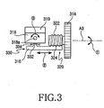
- Fig. 3 shows an internal configuration of the biaxially rotatable camera lens module according to the preferred embodiment of the present invention; and
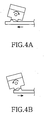
- Figs. 4A and 4B show the operation of the biaxially rotatable camera lens module according to the preferred embodiment of the present invention.
- Hereinafter, a preferred embodiment of the present invention will be described in detail with reference to the accompanying drawings. The following description of the present invention omits details of known functions and configurations to avoid making the subject matter of the present invention unclear.
- As shown in Fig. 1, a portable terminal employing a biaxially rotatable camera lens module according to the present invention comprises a
main housing 10, afolder 20 connected to the main housing in a foldable manner, and a hinge for joining themain housing 10 with thefolder 20 to be rotatable about a hinge axis A1 thereof, and acamera lens module 30 mounted at a predetermined position on themain housing 10 so as to be rotatable about two axes, A2 and A3. These two axes constitues an X axis corresponding to a first pivot axis A2 and a Y axis corresponding to a second pivot axis A3. - That is, the
camera lens module 30 is designed to be rotatable about the X axis as well as about the Y axis. It should be noted that even though thecamera lens module 30 is mounted at the predetermined position on the main housing (i.e. on the left upper portion of the main housing in Fig. 1), it may be mounted either on the right upper portion of themain housing 10 or at another predetermined position, such as on thefolder 20. - The
main housing 10 is provided with a plurality ofkeys 12 and amicrophone 14. At the predetermined position, specifically at a position adjacent to one of a pair ofmale arms 10b of the hinge which is provided on themain housing 10, the biaxially rotatablecamera lens module 30 is provided. Thecamera lens module 30 rotates about the X and Y axes. Specifically, thecamera lens module 30 is capable of rotating about the first pivot axis A2 within a first predetermined angle as well as about the second pivot axis A3 within a second predetermined angle. The first predetermined angle ranges from about 0 to 150 degrees, while the second predetermined angle ranges from about 0 to 30 degrees. - The
folder 20 includes aspeaker 22 on its inner surface and a liquid crystal display (LCD) 24 positioned near the speaker. The inner surface of the folder is a surface opposite to the camera lens module when the folder is closed toward the main housing. - The
camera lens module 30 includes acylindrical lens housing 310 and first and secondrotatable dials rotatable dial 312 mounted on one end of thelens housing 310, and the first axialrotatable dial 314 mounted on the other end opposite to and spaced from the one end of thelens housing 310 apart at a predetermined distance. Further, the axialrotatable dials - Configuration of the biaxially rotatable
camera lens module 30 according to the invention will be described below with reference to Figs. 2 and 3. As shown in Figs. 2 and 3, themodule 30 makes use of agear mechanism 320 and acam mechanism 330 so as to rotate alens frame 319 about two axes. Thegear mechanism 320 transforms a rotating motion of the first axialrotatable dial 314 into a linear motion of arack 316. Thecam mechanism 330 transforms the linear motion of therack 316 into a rotating motion of thelens frame 319. - The
gear mechanism 320 includes afirst gear 322 extending along a central rotating axis of the first axialrotatable dial 314 or along the second pivot axis A3, and asecond gear 324 causing therack 316 to move linearly in engagement with thefirst gear 322. Thecam mechanism 330 includes afirst cam 332 provided on one end, opposite to thesecond gear 324, of therack 316 and asecond cam 334 rotating acam body 318 about the first pivot axis A2. Thefirst cam 332 is provided on one end of therack 316 and thesecond gear 324 is provided on the other end of therack 316. Thesecond cam 334 is provided on a bottom of thecam body 318. - Preferably, the
first cam 332 has a convex shape, while thesecond cam 334 has a concave shape. Each of the first andsecond cams - The
cam body 318 and thelens frame 319 are integrally connected with each other. The cam body 31 preferably includes at least oneprotrusion 318a extending along the first pivot axis. - Further, a flexible printed circuit board (FPCB) F, which is connected to the
lens frame 319 shown in Fig. 2, extends to a main PCB, not shown, of themain housing 10 along the second pivot axis A3. - As shown in Figs. 3, 4a and 4b, when the Y axial
rotatable dial 314 rotates in a direction of an arrow ①, thefirst gear 322 also rotates in the same direction as the Y axial rotatable dial. Next, thesecond gear 324 engaged with thefirst gear 322 moves linearly in a direction of anarrow ②, and at the same time thefirst cam 332 also performs a linear movement. Subsequently, thesecond cam 334 engaged on thefirst cam 332 performs a sliding movement relative to thefirst cam 332 and rotates about the first pivot axis A2. These sequential operations occur almost simultaneously. - As seen from the foregoing, the biaxially roatable camera lens module according to the invention is designed to be rotatable in two directions and to be freely movable, depending on the position of an object to be photographed, so that the user can obtain a desired image without incurring inconvenience.
- It should be noted that the biaxially roatable camera lens module according to the invention does not need to be limited to the folder-type portable terminal, so that it is possible to be applied to all portable electronic equipments for taking a picture.
Claims (8)
- Biaxially rotatable camera lens module, comprising:a lens housing (310) with a lens (L);a first axial rotatable dial (314), mounted on one end of the lens housing (310), for rotating the lens (L) about a first pivot axis (A2, X);a second axial rotatable dial (312), mounted on the other end of the lens housing (10), for rotating the lens about a second pivot axis (A3, Y) perpendicular to the first pivot axis (A2, X);a gear mechanism (320) for transforming a first rotating motion of the first axial rotatable dial (314) into a linear motion; anda cam mechanism (330) for transforming the linear motion of the gear mechanism (320) into a second rotating motion and rotating the lens (L) about the first pivot axis (A2, X).
- Biaxially rotatable camera lens module according to claim 1 wherein the lens housing (10) is cylindrical.
- Biaxially rotatable camera lens module according to claim 1 or 2, wherein the gear mechanism (320) comprises a first gear (322) extending along a central rotating axis of the first axial rotatable dial (314), and a second gear (324) causing a rack (316) of the gear mechanism (320) to move linearly in engagement with the first gear (322).
- Biaxially rotatable camera lens module according to claim 1 or 2, wherein the cam mechanism (330) comprises a first convexly shaped cam (332) for cooperating with the linear motion, and a second concavely shaped cam (334) for rotating the lens about the first pivot axis (A2, X) during a sliding linear movement while being in contact with the first cam (332).
- Biaxially rotatable camera lens module according to claim 1 or 2, wherein the lens (L) further comprises a cam body (318) with which the cam mechanism (330) is integrally connected.
- Biaxially rotatable camera lens module according to claim 5, wherein the cam body (318) is formed with a protrusion (318a) extending along the first pivot axis (A2, X).
- Biaxially rotatable camera lens module according to claim 1, wherein the first pivot axis (A2, X) extends in a horizontal direction, and the second pivot axis extends (A3, Y) in a vertical direction.
- Biaxially rotatable camera lens module, comprising:a main housing (10); anda camera leans housing (310) mounted on a predetermined position of the main housing (10),wherein a camera lens (L) of the camera lens housing (310) is rotatable left and right on the basis of a first pivot axis and on the basis of the first pivot axis and the second axis perpendicular to the first pivot axis is rotatable up and down.
Applications Claiming Priority (2)
| Application Number | Priority Date | Filing Date | Title |
|---|---|---|---|
| KR10-2002-0064967A KR100480282B1 (en) | 2002-10-23 | 2002-10-23 | Two-rotational direction camera lenz module |
| KR2002064967 | 2002-10-23 |
Publications (2)
| Publication Number | Publication Date |
|---|---|
| EP1413820A2 true EP1413820A2 (en) | 2004-04-28 |
| EP1413820A3 EP1413820A3 (en) | 2007-02-28 |
Family
ID=32064976
Family Applications (1)
| Application Number | Title | Priority Date | Filing Date |
|---|---|---|---|
| EP03023982A Withdrawn EP1413820A3 (en) | 2002-10-23 | 2003-10-22 | Camera lens module rotatable around two axes |
Country Status (4)
| Country | Link |
|---|---|
| US (1) | US7411627B2 (en) |
| EP (1) | EP1413820A3 (en) |
| KR (1) | KR100480282B1 (en) |
| CN (1) | CN1333300C (en) |
Cited By (7)
| Publication number | Priority date | Publication date | Assignee | Title |
|---|---|---|---|---|
| EP1511312A1 (en) * | 2003-08-21 | 2005-03-02 | Samsung Electronics Co., Ltd. | Cameralens assembly for portable wireless terminals |
| EP1589744A2 (en) * | 2004-04-23 | 2005-10-26 | Symbol Technologies, Inc. | Scan head rotation at different optimum angles |
| CN102736392A (en) * | 2011-04-02 | 2012-10-17 | 瀚宇彩晶股份有限公司 | Electronic device |
| US10151606B1 (en) | 2016-02-24 | 2018-12-11 | Ommo Technologies, Inc. | Tracking position and movement using a magnetic field |
| US10276289B1 (en) | 2018-06-01 | 2019-04-30 | Ommo Technologies, Inc. | Rotating a permanent magnet in a position detection system |
| CN110260137A (en) * | 2019-06-19 | 2019-09-20 | 李嘉乐 | A kind of bluetooth Telescopic pick-up head |
| CN110825190A (en) * | 2019-11-28 | 2020-02-21 | 合肥联宝信息技术有限公司 | Foot pad mechanism and electronic equipment |
Families Citing this family (29)
| Publication number | Priority date | Publication date | Assignee | Title |
|---|---|---|---|---|
| US20060034601A1 (en) * | 2003-04-23 | 2006-02-16 | Tage Andersson | Multi-function two panel electronic device with 360° relative motion |
| US7426406B2 (en) * | 2003-04-23 | 2008-09-16 | Nokia Corporation | Mobile communications device with synchronising hinge |
| US7155266B2 (en) * | 2004-04-21 | 2006-12-26 | Nokia Corporation | Hinge for fold phone |
| US7512426B2 (en) * | 2003-04-23 | 2009-03-31 | Nokia Corporation | Mobile communications device with synchronising hinge |
| JP2004350206A (en) * | 2003-05-26 | 2004-12-09 | Sharp Corp | Imaging apparatus |
| KR20050066305A (en) * | 2003-12-26 | 2005-06-30 | 삼성전자주식회사 | Image photographing apparatus having appearing and disappearing lens unit |
| EP1735995A1 (en) * | 2004-04-05 | 2006-12-27 | Nokia Corporation | An electronic imaging device |
| KR100606003B1 (en) * | 2004-05-03 | 2006-07-26 | 삼성전자주식회사 | Portable wireless terminal |
| JP2006267391A (en) * | 2005-03-23 | 2006-10-05 | Mitsubishi Electric Corp | Imaging apparatus |
| US7414834B2 (en) * | 2005-04-21 | 2008-08-19 | Nokia Corporation | Mobile communications device with synchronising hinge |
| KR101142581B1 (en) * | 2005-05-13 | 2012-05-03 | 삼성전자주식회사 | Camera lens assembly for portable terminal |
| KR100703353B1 (en) * | 2005-05-30 | 2007-04-03 | 삼성전자주식회사 | Portable terminal with camera lens assembly |
| CN2849797Y (en) * | 2005-11-14 | 2006-12-20 | 鸿富锦精密工业(深圳)有限公司 | Electronic apparatus with camera module |
| CN101017321B (en) * | 2006-02-10 | 2010-05-12 | 鸿富锦精密工业(深圳)有限公司 | Portable electronic installation having pickup camera |
| CN101518071A (en) * | 2006-09-27 | 2009-08-26 | 皇家飞利浦电子股份有限公司 | Portable electronic device having a rotary camera unit |
| TW200823720A (en) * | 2006-11-27 | 2008-06-01 | Asustek Comp Inc | Portable computer |
| CN101236353B (en) * | 2007-01-31 | 2011-05-04 | 鸿富锦精密工业(深圳)有限公司 | Portable electronic device |
| TWM346834U (en) * | 2008-05-13 | 2008-12-11 | Simplo Technology Co Ltd | Display having image module with rotary pivot |
| CN101750698A (en) * | 2008-12-10 | 2010-06-23 | 深圳富泰宏精密工业有限公司 | Lens module and electronic device applying lens module |
| US9106814B2 (en) * | 2012-11-14 | 2015-08-11 | The United States of America as represented by the Federal Bureau of Investigation, Dept. of Justice | Apparatuses for rotating a sensing device |
| US9749510B2 (en) * | 2014-12-25 | 2017-08-29 | Panasonic Intellectual Property Management Co., Ltd. | Imaging unit and imaging apparatus |
| CN106453728A (en) * | 2016-12-07 | 2017-02-22 | 深圳市传奇数码有限公司 | Rotary camera for mobile phone |
| CN207196002U (en) * | 2017-09-25 | 2018-04-06 | 深圳市商汤科技有限公司 | Authenticating device |
| TWI698734B (en) * | 2018-01-18 | 2020-07-11 | 仁寶電腦工業股份有限公司 | Electronic device |
| CN108600449B (en) * | 2018-04-23 | 2020-12-29 | 京东方科技集团股份有限公司 | Display device |
| CN109274879B (en) * | 2018-11-16 | 2023-11-21 | 歌尔光学科技有限公司 | Camera telescopic assembly and electronic product |
| CN110570767A (en) * | 2019-09-10 | 2019-12-13 | 京东方科技集团股份有限公司 | Flexible display screen, manufacturing method and using method thereof and terminal equipment |
| CN114827390B (en) * | 2021-01-22 | 2023-10-20 | 广州视源电子科技股份有限公司 | Angle-adjustable camera structure and interaction panel |
| CN118328254B (en) * | 2024-06-12 | 2024-08-16 | 四川航天职业技术学院(四川航天高级技工学校) | Outdoor photographic usefulness Intelligent tripod |
Citations (3)
| Publication number | Priority date | Publication date | Assignee | Title |
|---|---|---|---|---|
| US5414444A (en) * | 1994-03-30 | 1995-05-09 | At&T Corp. | Personal communicator having orientable video imaging element |
| US5715138A (en) * | 1995-10-19 | 1998-02-03 | Daewoo Electronics Co., Ltd. | Apparatus for providing a display with tilting and rotating movements with rack, pinion, and bevel gears |
| EP0898405A2 (en) * | 1997-08-22 | 1999-02-24 | Hitachi, Ltd. | Information communication terminal device |
Family Cites Families (16)
| Publication number | Priority date | Publication date | Assignee | Title |
|---|---|---|---|---|
| US4163613A (en) * | 1978-01-27 | 1979-08-07 | Eastman Kodak Company | Camera focus or exposure adjustment mechanism |
| JP3183056B2 (en) * | 1994-08-26 | 2001-07-03 | 株式会社日立製作所 | Imaging device |
| JPH1075287A (en) * | 1996-08-30 | 1998-03-17 | Kokusai Electric Co Ltd | Portable video telephone |
| US5701532A (en) * | 1997-01-23 | 1997-12-23 | Inaba; Minoru | Lens adjustment device of stereo camera |
| CN2319976Y (en) * | 1997-11-21 | 1999-05-19 | 升谷电子股份有限公司 | Driving mechanism of semi-spherical monitor |
| CN2328030Y (en) * | 1998-01-26 | 1999-07-07 | 力捷电脑股份有限公司 | Lens moving mechanism of digital camera |
| US5930544A (en) * | 1998-04-20 | 1999-07-27 | Umax Data Systems Inc. | Lens movement mechanism for digital camera |
| GB9828792D0 (en) * | 1998-12-29 | 1999-02-17 | Vitec Group Plc | Improvements in or relating to mountings for optical apparatus |
| JP2000270069A (en) * | 1999-03-16 | 2000-09-29 | Canon Inc | Portable information terminal with digital camera |
| JP2001157093A (en) * | 1999-11-30 | 2001-06-08 | Aiphone Co Ltd | Panning and tilting structure for door slave set with camera |
| KR100430595B1 (en) * | 1999-12-30 | 2004-05-10 | 삼성전자주식회사 | Radiotelephone for visual communication |
| KR20010068807A (en) * | 2000-01-10 | 2001-07-23 | 윤종용 | Radiotelephone for visual communication |
| US6532035B1 (en) * | 2000-06-29 | 2003-03-11 | Nokia Mobile Phones Ltd. | Method and apparatus for implementation of close-up imaging capability in a mobile imaging system |
| JP2002073207A (en) * | 2000-08-29 | 2002-03-12 | Sony Corp | Portable information terminal mounted with camera |
| KR20030006730A (en) * | 2001-07-14 | 2003-01-23 | 엘지전자 주식회사 | Video mobile terminal |
| KR100471148B1 (en) * | 2002-06-05 | 2005-02-21 | 삼성전기주식회사 | Cellular Phone equipped with a camera |
-
2002
- 2002-10-23 KR KR10-2002-0064967A patent/KR100480282B1/en not_active IP Right Cessation
-
2003
- 2003-10-22 EP EP03023982A patent/EP1413820A3/en not_active Withdrawn
- 2003-10-22 CN CNB2003101025258A patent/CN1333300C/en not_active Expired - Fee Related
- 2003-10-23 US US10/691,732 patent/US7411627B2/en not_active Expired - Fee Related
Patent Citations (3)
| Publication number | Priority date | Publication date | Assignee | Title |
|---|---|---|---|---|
| US5414444A (en) * | 1994-03-30 | 1995-05-09 | At&T Corp. | Personal communicator having orientable video imaging element |
| US5715138A (en) * | 1995-10-19 | 1998-02-03 | Daewoo Electronics Co., Ltd. | Apparatus for providing a display with tilting and rotating movements with rack, pinion, and bevel gears |
| EP0898405A2 (en) * | 1997-08-22 | 1999-02-24 | Hitachi, Ltd. | Information communication terminal device |
Cited By (13)
| Publication number | Priority date | Publication date | Assignee | Title |
|---|---|---|---|---|
| EP1843589A2 (en) * | 2003-08-21 | 2007-10-10 | Samsung Electronics Co., Ltd. | Camera lens assembly for portable wireless terminals |
| EP1511312A1 (en) * | 2003-08-21 | 2005-03-02 | Samsung Electronics Co., Ltd. | Cameralens assembly for portable wireless terminals |
| EP1843589A3 (en) * | 2003-08-21 | 2009-09-30 | Samsung Electronics Co., Ltd. | Camera lens assembly for portable wireless terminals |
| US7746511B2 (en) | 2004-04-23 | 2010-06-29 | Symbol Technologies, Inc. | Scan head rotation at different optimum angles |
| EP1589744A3 (en) * | 2004-04-23 | 2005-11-16 | Symbol Technologies, Inc. | Scan head rotation at different optimum angles |
| JP2005310165A (en) * | 2004-04-23 | 2005-11-04 | Symbol Technologies Inc | Rotation of scan head at various optimal angle |
| EP1589744A2 (en) * | 2004-04-23 | 2005-10-26 | Symbol Technologies, Inc. | Scan head rotation at different optimum angles |
| CN102736392A (en) * | 2011-04-02 | 2012-10-17 | 瀚宇彩晶股份有限公司 | Electronic device |
| US10151606B1 (en) | 2016-02-24 | 2018-12-11 | Ommo Technologies, Inc. | Tracking position and movement using a magnetic field |
| US10704929B1 (en) | 2016-02-24 | 2020-07-07 | Ommo Technologies, Inc. | Tracking position and movement using a magnetic field |
| US10276289B1 (en) | 2018-06-01 | 2019-04-30 | Ommo Technologies, Inc. | Rotating a permanent magnet in a position detection system |
| CN110260137A (en) * | 2019-06-19 | 2019-09-20 | 李嘉乐 | A kind of bluetooth Telescopic pick-up head |
| CN110825190A (en) * | 2019-11-28 | 2020-02-21 | 合肥联宝信息技术有限公司 | Foot pad mechanism and electronic equipment |
Also Published As
| Publication number | Publication date |
|---|---|
| KR100480282B1 (en) | 2005-04-07 |
| EP1413820A3 (en) | 2007-02-28 |
| KR20040036150A (en) | 2004-04-30 |
| CN1333300C (en) | 2007-08-22 |
| US20040080667A1 (en) | 2004-04-29 |
| US7411627B2 (en) | 2008-08-12 |
| CN1497317A (en) | 2004-05-19 |
Similar Documents
| Publication | Publication Date | Title |
|---|---|---|
| US7411627B2 (en) | Biaxially rotatable camera lens module | |
| EP1499094B1 (en) | Bi-directional sliding-type portable terminal comprising a camera | |
| CN101051847B (en) | Portable terminal and sliding type cradle for the same | |
| US7480524B2 (en) | Portable communication terminal in slant positions for displaying information | |
| EP1610530B1 (en) | Dual-axis rotation folder-type portable apparatus | |
| EP1698154B1 (en) | Mobile phone configuration | |
| KR100703402B1 (en) | Mobile phone having camera lens module with multi-direction | |
| US7353050B2 (en) | Portable digital communication apparatus with reversible dual-axis hinge | |
| KR20040034346A (en) | Portable communication device | |
| US20070146977A1 (en) | Sliding and folding type portable terminal | |
| EP1653713B1 (en) | Portable and foldable communication terminal | |
| JP2008014497A (en) | Hinge device for portable wireless terminal | |
| WO2006073509A1 (en) | Flipper phone configuration | |
| EP1587284B1 (en) | Portable terminal with touch key | |
| EP1814285A1 (en) | Sliding/swing-type portable terminal capable of positioning liquid crystal display at center portion thereof and method of using the same | |
| EP1650934B1 (en) | Foldable phone with a 3d hinge and a camera in the hinge | |
| US20050245296A1 (en) | Portable dual hinge type communication device usable as personal digital assistant | |
| JP2003018261A (en) | Portable terminal equipment | |
| KR100575935B1 (en) | Dual rotation axis-type mobile phone | |
| US7251511B2 (en) | Portable communication apparatus with data-inputting expansion | |
| KR100469855B1 (en) | Portable communication device | |
| JP2005124127A (en) | Mobile unit | |
| JP2003032336A (en) | Electronic equipment | |
| KR20070017856A (en) | Folding-type mobile phone with character inputting convenience | |
| KR20060019713A (en) | Folder type mobile communication terminal |
Legal Events
| Date | Code | Title | Description |
|---|---|---|---|
| PUAI | Public reference made under article 153(3) epc to a published international application that has entered the european phase |
Free format text: ORIGINAL CODE: 0009012 |
|
| 17P | Request for examination filed |
Effective date: 20031022 |
|
| AK | Designated contracting states |
Kind code of ref document: A2 Designated state(s): AT BE BG CH CY CZ DE DK EE ES FI FR GB GR HU IE IT LI LU MC NL PT RO SE SI SK TR |
|
| AX | Request for extension of the european patent |
Extension state: AL LT LV MK |
|
| PUAL | Search report despatched |
Free format text: ORIGINAL CODE: 0009013 |
|
| AK | Designated contracting states |
Kind code of ref document: A3 Designated state(s): AT BE BG CH CY CZ DE DK EE ES FI FR GB GR HU IE IT LI LU MC NL PT RO SE SI SK TR |
|
| AX | Request for extension of the european patent |
Extension state: AL LT LV MK |
|
| 17Q | First examination report despatched |
Effective date: 20070419 |
|
| AKX | Designation fees paid |
Designated state(s): DE FR GB |
|
| STAA | Information on the status of an ep patent application or granted ep patent |
Free format text: STATUS: THE APPLICATION IS DEEMED TO BE WITHDRAWN |
|
| 18D | Application deemed to be withdrawn |
Effective date: 20080911 |