EP1413739A2 - Constant velocity radial inflow particle separator - Google Patents
Constant velocity radial inflow particle separator Download PDFInfo
- Publication number
- EP1413739A2 EP1413739A2 EP03012584A EP03012584A EP1413739A2 EP 1413739 A2 EP1413739 A2 EP 1413739A2 EP 03012584 A EP03012584 A EP 03012584A EP 03012584 A EP03012584 A EP 03012584A EP 1413739 A2 EP1413739 A2 EP 1413739A2
- Authority
- EP
- European Patent Office
- Prior art keywords
- airflow
- air cleaner
- recited
- cyclone chamber
- cleaner system
- Prior art date
- Legal status (The legal status is an assumption and is not a legal conclusion. Google has not performed a legal analysis and makes no representation as to the accuracy of the status listed.)
- Granted
Links
Images

Classifications
-
- F—MECHANICAL ENGINEERING; LIGHTING; HEATING; WEAPONS; BLASTING
- F02—COMBUSTION ENGINES; HOT-GAS OR COMBUSTION-PRODUCT ENGINE PLANTS
- F02M—SUPPLYING COMBUSTION ENGINES IN GENERAL WITH COMBUSTIBLE MIXTURES OR CONSTITUENTS THEREOF
- F02M35/00—Combustion-air cleaners, air intakes, intake silencers, or induction systems specially adapted for, or arranged on, internal-combustion engines
- F02M35/02—Air cleaners
- F02M35/022—Air cleaners acting by gravity, by centrifugal, or by other inertial forces, e.g. with moistened walls
-
- B—PERFORMING OPERATIONS; TRANSPORTING
- B01—PHYSICAL OR CHEMICAL PROCESSES OR APPARATUS IN GENERAL
- B01D—SEPARATION
- B01D45/00—Separating dispersed particles from gases or vapours by gravity, inertia, or centrifugal forces
- B01D45/12—Separating dispersed particles from gases or vapours by gravity, inertia, or centrifugal forces by centrifugal forces
- B01D45/16—Separating dispersed particles from gases or vapours by gravity, inertia, or centrifugal forces by centrifugal forces generated by the winding course of the gas stream, the centrifugal forces being generated solely or partly by mechanical means, e.g. fixed swirl vanes
Definitions
- the present invention relates to the removal of particulate from a flow of ambient air, and more particularly to a vehicle air cleaner which provides a constant intake airflow velocity.
- Vehicles commonly include an air cleaner system which removes particulate matter from airflow which is provided to a vehicle engine. Air cleaning is frequently achieved by cyclone-type devices which communicate intake airflow about a series of offset radiuses to separate out undesirable particles through centripetal acceleration.
- Conventional cyclone-type devices must provide a high angular speed at low airflow to assure an angular speed sufficient to separate out the undesirable particles.
- the low airflow condition may be of particular concern as the vehicle is typically stationary or slowly moving and more likely to be surrounded by a large volume of undesirable particles.
- the angular velocity through the cyclone-type device will be quite high when the vehicle is travelling at high speed. This high airflow condition generates a relatively large pressure drop across the air cleaner system which may decrease engine power through air starvation.
- the vehicle air cleaner system includes a cyclone chamber.
- the particles are separated from the airflow through centripetal acceleration such that the relatively heavier undesirable particles are ejected through apertures in an outer surface of the cyclone chamber.
- a conventional media filter is located adjacent an outlet to provide additional filtration of the airflow prior to communication to a vehicle engine.
- variable inlet is located within the inlet to the cyclone chamber.
- the variable inlet communicates airflow to the cyclone chamber at a relatively constant velocity by varying an opening in response to airflow.
- One variable inlet includes a piston which selectively restricts the inlet.
- the piston is maintained toward a restricted position.
- the restricted position increases the angular velocity of the airflow by directing airflow toward smaller radii within the cyclone chamber.
- the airflow through the variable inlet is directed toward the outer diameter of the cyclone chamber and larger radii to assure an angular speed sufficient to separate out undesirable particles yet prevent an undesirable pressure drop across the air cleaner system.
- Another variable inlet includes a movable valve which varies the variable inlet in response to a controller.
- the valve is opened to lower the angular velocity of the airflow by directing airflow toward a larger radius.
- the valve is closed to increase the angular velocity of the airflow by directing airflow toward the smaller radiuses.
- the valve may be operated to compensate for conditions no directly related to airflow velocity.
- the present invention therefore effectively removes particulate matter while maintaining a relative constant airflow velocity therethrough.
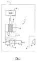
- FIG. 1 illustrates a general sectional view of an air cleaner system 10 for a vehicle (illustrated schematically at 11).
- the system 10 includes an inlet 12, a cyclone chamber 14 and an outlet 16.
- the inlet 12 communicates ambient air from an intake 18 to the cyclone chamber and the outlet communicates cleaned air from the cyclone chamber 14 to vehicle engine 20.
- Intake 18 is typically placed in a vehicle location 22 which provides sufficient airflow for operation of the engine 20. It should be understood that various intake systems and power plants will benefit from the present invention.
- the cyclone chamber 14 preferably includes a series of offset cylinders 24 (best seen in Figure 2 and 3) which rotate airflow from the inlet 12 at an angular speed sufficient to separate out undesirable particles. It should be understood that other cyclone configurations such as spirals and other configurations which provide an angular velocity will benefit from the present invention. Undesirable particles are separated from the airflow through centripetal acceleration such that the relatively heavier undesirable particles are ejected from apertures 26 through an outer surface of the cyclone chamber 14.
- a conventional media filter 28 is located adjacent the outlet 16 to provide additional filtration of the airflow prior to communication to the engine 20.
- a variable inlet 30 is preferably located within the inlet 12.
- the variable inlet 30 communicates airflow to the cyclone chamber 14 at a relatively constant cyclone airflow velocity by varying an opening 32 in response to airflow (illustrated schematically by arrow A) which enters the inlet 12.
- Cyclone airflow velocity is defined herein as revolutions per second. It should be understood that the intake airflow A will vary in velocity due at least to engine and vehicle speed, however, by adjusting the variable inlet 30 the airflow velocity entering the cyclone chamber is managed to be relatively constant.
- a flex diaphragm system 33 having a pressure-balanced piston 34 varies the variable inlet 30 and the airflow A through inlet 12.
- the piston 34 moves within a sealed chamber 36 to selectively restrict the opening 32 and offset airflow therethrough.
- the sealed chamber 36 communicates with the cyclone chamber 14 and the pressure therein through a passage 38.
- the pressure-balanced piston 34 is balanced by communication of pressure between the cyclone chamber 14 and a volume 40 within chamber 36 through passage 38.
- a biasing member such as a spring 44 drives the piston 34 along a guide 46 to bias the piston 34 toward a closed or restricted position.
- the piston 34 selectively restricts the inlet 12 in response to the airflow A.
- the piston 34 is maintained toward the restricted position by the bias of spring 44.
- the piston 34 in the restricted position provides a relatively small opening 32 which is closer to a center C of the cyclone chamber 14. That is, a longitudinal center axis 46 of opening 32 shifts toward center C (as represented by phantom axis 46').
- Air flow A through variable inlet 30 is thereby directed toward the center C of the cyclone chamber 14 which increase the angular velocity of the airflow by directing airflow toward the smaller radii 42s.
- the variable inlet 32 assures an angular velocity sufficient to separate out undesirable particles.
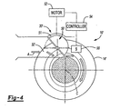
- a movable valve 50 varies the variable inlet 30' and the airflow A through opening 32.
- the valve 50 preferably includes a hemi-circular portion 51 which matches the inner surface of the variable inlet 32'. Opening and closing of the valve 50 offsets airflow therethrough.
- the valve 50 is rotated between an opened (in phantom) and closed position by an electric motor 52 or the like.
- a controller 54 which communicates with a sensor 56 located within the cyclone chamber 14' drives the motor 52. In response to the sensor 56, the controller 54 selectively moves the valve 50 to mask a portion of the variable inlet 32' and offset the airflow A relative the center C of the cyclone chamber 14'.
- valve 50 is opened to lower the angular velocity of the airflow by directing airflow toward larger radii 42 L.
- the valve 50 is closed to increase the angular velocity of the airflow by directing airflow toward smaller radii.
- Controller 54 preferably includes logic to operate the valve 50 in response to predetermined conditions. That is, as the valve 50 is operated by the motor 52, the air cleaner system 10' is operated to compensate for conditions not directly related to airflow velocity. For example, controller 54 may operate the air cleaner system 10' at a relatively higher angular velocity in response to the detection of a high concentration of particulate, the engine is operating at high wear condition, and/or the media filter 28 is wet and/or full.
Landscapes
- Engineering & Computer Science (AREA)
- Chemical & Material Sciences (AREA)
- Chemical Kinetics & Catalysis (AREA)
- Combustion & Propulsion (AREA)
- Mechanical Engineering (AREA)
- General Engineering & Computer Science (AREA)
- Cyclones (AREA)
Abstract
Description
- The present invention relates to the removal of particulate from a flow of ambient air, and more particularly to a vehicle air cleaner which provides a constant intake airflow velocity.
- Vehicles commonly include an air cleaner system which removes particulate matter from airflow which is provided to a vehicle engine. Air cleaning is frequently achieved by cyclone-type devices which communicate intake airflow about a series of offset radiuses to separate out undesirable particles through centripetal acceleration.
- Conventional cyclone-type devices must provide a high angular speed at low airflow to assure an angular speed sufficient to separate out the undesirable particles. The low airflow condition may be of particular concern as the vehicle is typically stationary or slowly moving and more likely to be surrounded by a large volume of undesirable particles. However, by designing the cyclone-type device to provide sufficient angular speed in the low airflow condition, the angular velocity through the cyclone-type device will be quite high when the vehicle is travelling at high speed. This high airflow condition generates a relatively large pressure drop across the air cleaner system which may decrease engine power through air starvation.
- Accordingly, it is desirable to provide an air cleaner system which effectively removes particulate matter while maintaining a relative constant airflow velocity.
- The vehicle air cleaner system according to the present invention includes a cyclone chamber. The particles are separated from the airflow through centripetal acceleration such that the relatively heavier undesirable particles are ejected through apertures in an outer surface of the cyclone chamber. A conventional media filter is located adjacent an outlet to provide additional filtration of the airflow prior to communication to a vehicle engine.
- A variable inlet is located within the inlet to the cyclone chamber. The variable inlet communicates airflow to the cyclone chamber at a relatively constant velocity by varying an opening in response to airflow.
- One variable inlet includes a piston which selectively restricts the inlet. During a relatively low airflow condition the piston is maintained toward a restricted position. The restricted position increases the angular velocity of the airflow by directing airflow toward smaller radii within the cyclone chamber. During a relatively high airflow condition the airflow through the variable inlet is directed toward the outer diameter of the cyclone chamber and larger radii to assure an angular speed sufficient to separate out undesirable particles yet prevent an undesirable pressure drop across the air cleaner system. By varying communication of airflow to particular radii within the cyclone chamber, a relatively constant pressure drop across the air cleaner system is provided regardless of airflow velocity.
- Another variable inlet includes a movable valve which varies the variable inlet in response to a controller. During a high airflow condition, the valve is opened to lower the angular velocity of the airflow by directing airflow toward a larger radius. During a low airflow condition, the valve is closed to increase the angular velocity of the airflow by directing airflow toward the smaller radiuses. As the value is independently powered, the valve may be operated to compensate for conditions no directly related to airflow velocity.
- The present invention therefore effectively removes particulate matter while maintaining a relative constant airflow velocity therethrough.
- The various features and advantages of this invention will become apparent to those skilled in the art from the following detailed description of the currently preferred embodiment. The drawings that accompany the detailed description can be briefly described as follows:
- Figure 1 is a schematic sectional view of a vehicle air cleaner system according to the present invention;
- Figure 2 is a schematic view of an air cleaner system in a first position;
- Figure 3 is a schematic view of the air cleaner system of Figure 2 in a second position; and
- Figure 4 is a schematic view of another air cleaner system in a first position;
- Figure 1 illustrates a general sectional view of an
air cleaner system 10 for a vehicle (illustrated schematically at 11). Thesystem 10 includes aninlet 12, acyclone chamber 14 and anoutlet 16. Theinlet 12 communicates ambient air from anintake 18 to the cyclone chamber and the outlet communicates cleaned air from thecyclone chamber 14 tovehicle engine 20. Intake 18 is typically placed in avehicle location 22 which provides sufficient airflow for operation of theengine 20. It should be understood that various intake systems and power plants will benefit from the present invention. - The
cyclone chamber 14 preferably includes a series of offset cylinders 24 (best seen in Figure 2 and 3) which rotate airflow from theinlet 12 at an angular speed sufficient to separate out undesirable particles. It should be understood that other cyclone configurations such as spirals and other configurations which provide an angular velocity will benefit from the present invention. Undesirable particles are separated from the airflow through centripetal acceleration such that the relatively heavier undesirable particles are ejected fromapertures 26 through an outer surface of thecyclone chamber 14. Aconventional media filter 28 is located adjacent theoutlet 16 to provide additional filtration of the airflow prior to communication to theengine 20. - A
variable inlet 30 is preferably located within theinlet 12. Thevariable inlet 30 communicates airflow to thecyclone chamber 14 at a relatively constant cyclone airflow velocity by varying anopening 32 in response to airflow (illustrated schematically by arrow A) which enters theinlet 12. Cyclone airflow velocity is defined herein as revolutions per second. It should be understood that the intake airflow A will vary in velocity due at least to engine and vehicle speed, however, by adjusting thevariable inlet 30 the airflow velocity entering the cyclone chamber is managed to be relatively constant. - Referring to Figure 2, a
flex diaphragm system 33 having a pressure-balancedpiston 34 varies thevariable inlet 30 and the airflow A throughinlet 12. Thepiston 34 moves within a sealedchamber 36 to selectively restrict the opening 32 and offset airflow therethrough. The sealedchamber 36 communicates with thecyclone chamber 14 and the pressure therein through apassage 38. The pressure-balancedpiston 34 is balanced by communication of pressure between thecyclone chamber 14 and avolume 40 withinchamber 36 throughpassage 38. A biasing member such as aspring 44 drives thepiston 34 along aguide 46 to bias thepiston 34 toward a closed or restricted position. - The
piston 34 selectively restricts theinlet 12 in response to the airflow A. During a relatively low airflow condition thepiston 34 is maintained toward the restricted position by the bias ofspring 44. Thepiston 34 in the restricted position provides a relativelysmall opening 32 which is closer to a center C of thecyclone chamber 14. That is, alongitudinal center axis 46 of opening 32 shifts toward center C (as represented by phantom axis 46'). Air flow A throughvariable inlet 30 is thereby directed toward the center C of thecyclone chamber 14 which increase the angular velocity of the airflow by directing airflow toward the smaller radii 42s. Thus, even during a relatively low airflow condition thevariable inlet 32 assures an angular velocity sufficient to separate out undesirable particles. - During a relatively high airflow condition the pressure within
volume 40 operates effectively as a vacuum relative thecyclone cylinder 14 to overcome thespring 44 and pull thepiston 34 toward the unrestricted position (Figure 3). Thepiston 34 in the unrestricted position provides a relativelylarge opening 32 throughvariable inlet 30 which is offset away from the center C of thecyclone chamber 14. Air flow A throughvariable inlet 30 is thereby directed toward the larger diameter ofradii 42 L of thecyclone chamber 14 which effectively lowers the angular velocity. The angular velocity is sufficient to separate out undesirable particles yet prevents an undesirable pressure drop across theair cleaner system 10. By varying communication of airflow to particular radii within the cyclone chamber, a relatively constant pressure drop across the air cleaner system is provided regardless of airflow velocity. That is, the cyclone airflow velocity is maintained substantially constant through communication with particular radii. - Referring to Figure 4, another vehicle air cleaner system 10' is illustrated. A
movable valve 50 varies the variable inlet 30' and the airflow A throughopening 32. Thevalve 50 preferably includes a hemi-circular portion 51 which matches the inner surface of the variable inlet 32'. Opening and closing of thevalve 50 offsets airflow therethrough. - The
valve 50 is rotated between an opened (in phantom) and closed position by anelectric motor 52 or the like. Acontroller 54 which communicates with asensor 56 located within the cyclone chamber 14' drives themotor 52. In response to thesensor 56, thecontroller 54 selectively moves thevalve 50 to mask a portion of the variable inlet 32' and offset the airflow A relative the center C of the cyclone chamber 14'. - During a high airflow condition, the
valve 50 is opened to lower the angular velocity of the airflow by directing airflow toward larger radii 42 L. During a low airflow condition, thevalve 50 is closed to increase the angular velocity of the airflow by directing airflow toward smaller radii. -
Controller 54 preferably includes logic to operate thevalve 50 in response to predetermined conditions. That is, as thevalve 50 is operated by themotor 52, the air cleaner system 10' is operated to compensate for conditions not directly related to airflow velocity. For example,controller 54 may operate the air cleaner system 10' at a relatively higher angular velocity in response to the detection of a high concentration of particulate, the engine is operating at high wear condition, and/or themedia filter 28 is wet and/or full. - The foregoing description is exemplary rather than defined by the limitations within. Many modifications and variations of the present invention are possible in light of the above teachings. The preferred embodiments of this invention have been disclosed, however, one of ordinary skill in the art would recognize that certain modifications would come within the scope of this invention. It is, therefore, to be understood that within the scope of the appended claims, the invention may be practiced otherwise than as specifically described. For that reason the following claims should be studied to determine the true scope and content of this invention.
Claims (16)
- A vehicle air cleaner system comprising:a cyclone chamber; anda variable inlet which selectively restricts airflow to said cyclone chamber to maintain a relatively constant cyclone airflow velocity.
- The vehicle air cleaner system as recited in claim 1, further comprising a flex diaphragm system to vary an opening within said variable inlet.
- The vehicle air cleaner system as recited in claim 2, wherein said flex diaphragm system comprises a biased pressure balanced piston.
- The vehicle air cleaner system as recited in claim 1, further comprising a movable valve to vary an opening within said variable inlet.
- The vehicle air cleaner system as recited in claim 4, wherein said movable valve comprises a hemi-circular portion to at least partially block said opening within said variable inlet.
- The vehicle air cleaner system as recited in claim 4, further comprising a motor to rotate said movable valve.
- The vehicle air cleaner system as recited in claim 1, wherein said cyclone chamber comprises a plurality of offset radii.
- The vehicle air cleaner system as recited in claim 1, further comprising a media filter adjacent an outlet from said cyclone chamber.
- A method of operating an air cleaner system comprising the steps of:(1) directing airflow into a cyclone chamber to maintain relatively constant cyclone airflow velocity.
- A method as recited in claim 9, further comprising the step of:(a) directing airflow to one of a plurality of radii within the cyclone chamber.
- A method as recited in claim 9, further comprising the step of:(a) controlling an inlet to the cyclone chamber to maintain the relatively constant airflow velocity into the cyclone chamber.
- A method as recited in claim 11, wherein said step (a) further comprises selectively restricting the inlet.
- A method as recited in claim 9, wherein said step (1) further comprises increasing the angular velocity to compensate for predetermined air cleaner system conditions.
- A method of operating an air cleaner system comprising the steps of:(1) controlling an inlet to the cyclone chamber to maintain a relatively constant cyclone airflow velocity; and(2) offsetting the airflow within the inlet toward one of a plurality of radii within the cyclone chamber.
- A method as recited in claim 14, wherein said step (1) further comprises selectively restricting the inlet.
- A method as recited in claim 9, wherein said step (2) further comprises increasing an angular velocity of the airflow within the cyclone chamber in response to a predetermined air cleaner system condition.
Applications Claiming Priority (2)
| Application Number | Priority Date | Filing Date | Title |
|---|---|---|---|
| US10/278,406 US6755897B2 (en) | 2002-10-23 | 2002-10-23 | Constant velocity radial inflow particle separator |
| US278406 | 2002-10-23 |
Publications (3)
| Publication Number | Publication Date |
|---|---|
| EP1413739A2 true EP1413739A2 (en) | 2004-04-28 |
| EP1413739A3 EP1413739A3 (en) | 2005-11-23 |
| EP1413739B1 EP1413739B1 (en) | 2018-01-24 |
Family
ID=32069329
Family Applications (1)
| Application Number | Title | Priority Date | Filing Date |
|---|---|---|---|
| EP03012584.3A Expired - Lifetime EP1413739B1 (en) | 2002-10-23 | 2003-06-03 | Constant velocity radial inflow particle separator |
Country Status (2)
| Country | Link |
|---|---|
| US (1) | US6755897B2 (en) |
| EP (1) | EP1413739B1 (en) |
Cited By (2)
| Publication number | Priority date | Publication date | Assignee | Title |
|---|---|---|---|---|
| WO2008122868A2 (en) | 2007-04-06 | 2008-10-16 | Bmc S.R.L. | Filtering device for the air taken in by the engine of a vehicle provided with a partialization element |
| DE102017010542A1 (en) | 2016-11-23 | 2018-05-24 | Scania Cv Ab | Air distribution system |
Families Citing this family (7)
| Publication number | Priority date | Publication date | Assignee | Title |
|---|---|---|---|---|
| US20050034946A1 (en) * | 2003-03-12 | 2005-02-17 | Jeffrey Krantz | System and method for removing pollutants from a roadway |
| US7066129B2 (en) * | 2003-10-06 | 2006-06-27 | General Motors Corporation | Intake manifold and runner apparatus |
| US7802433B2 (en) * | 2006-09-27 | 2010-09-28 | General Electric Company | Adaptive inertial particle separators and methods of use |
| GB201113072D0 (en) * | 2011-07-29 | 2011-09-14 | Parker Hannifin Mfg Uk Ltd | A separator |
| EP2735352A1 (en) | 2012-11-23 | 2014-05-28 | Alfa Laval Corporate AB | A centrifugal separator |
| EP2735351B1 (en) | 2012-11-23 | 2014-12-31 | Alfa Laval Corporate AB | Centrifugal separator for separating particles from a gas stream |
| GB2527787B (en) * | 2014-07-02 | 2017-01-18 | Dyson Technology Ltd | Vacuum cleaner |
Family Cites Families (37)
| Publication number | Priority date | Publication date | Assignee | Title |
|---|---|---|---|---|
| DE1519958B2 (en) * | 1964-09-29 | 1977-03-03 | Berz, Max, Dipl.-Ing.; Berz, Wolfgang, Dipl.-Ing.; 8113 Kochel | DEVICE FOR SEPARATING SOLID PARTICLES |
| US3577728A (en) * | 1969-03-19 | 1971-05-04 | Joe W Von Brimer | Exhaust gas processing system |
| DE2756751C2 (en) * | 1977-12-20 | 1982-10-14 | Filterwerk Mann & Hummel Gmbh, 7140 Ludwigsburg | Air filter for cleaning the intake air of air-sucking machines |
| JPS54141917A (en) * | 1978-04-25 | 1979-11-05 | Toyota Motor Corp | Centrifugal separation type air cleaner for internal combustion engine |
| US4592765A (en) * | 1985-01-15 | 1986-06-03 | Pratt & Whitney Canada Inc. | Inertial separator |
| US4606743A (en) * | 1985-06-28 | 1986-08-19 | Shuman Curtis F | Two stage engine air breather filter |
| US5039317A (en) * | 1990-07-05 | 1991-08-13 | Allied-Signal Inc. | Radial inflow particle separation method and apparatus |
| RU2107183C1 (en) * | 1992-08-22 | 1998-03-20 | Акционерное общество "АвтоВАЗ" | Internal combustion engine intake device |
| RU2095612C1 (en) * | 1992-08-22 | 1997-11-10 | Акционерное общество "АвтоВАЗ" | Intake device for internal combustion engine |
| DE4404709C1 (en) * | 1994-02-15 | 1995-06-08 | Freudenberg Carl Fa | Separator of liquid from liquid-bearing gas |
| JP3299622B2 (en) * | 1994-03-11 | 2002-07-08 | 豊田紡織株式会社 | Air cleaner device |
| JP3210825B2 (en) * | 1995-01-14 | 2001-09-25 | ヤマハ発動機株式会社 | V-type multi-cylinder engine intake system |
| US5660243A (en) * | 1995-02-13 | 1997-08-26 | Chrysler Corporation | Air flow, atmospheric particle, and environmental element diverter system |
| US5551387A (en) * | 1995-02-24 | 1996-09-03 | Ortech Corporation | Tuned intake manifold for OTTO cycle engines |
| FR2734026B1 (en) * | 1995-05-10 | 1997-07-18 | Magneti Marelli France | INTAKE MANIFOLD FOR INTERNAL COMBUSTION ENGINE AND MANUFACTURING METHOD THEREOF |
| FR2734603B1 (en) * | 1995-05-23 | 1997-07-25 | Magneti Marelli France | INTAKE MANIFOLD WITH ANNULATED AIR TUBES, FOR INTERNAL COMBUSTION ENGINE |
| DE19519438A1 (en) * | 1995-05-26 | 1996-11-28 | Mann & Hummel Filter | Air filters, in particular for cleaning combustion air for internal combustion engines |
| JPH0953528A (en) * | 1995-08-10 | 1997-02-25 | Yamaha Motor Co Ltd | Multi-cylinder engine with intake system |
| US5596961A (en) * | 1995-10-02 | 1997-01-28 | Detroit Diesel Corporation | Intake manifold assembly for four-cycle internal combustion engine |
| JPH09291859A (en) * | 1996-04-30 | 1997-11-11 | Suzuki Motor Corp | Outboard air intake system |
| JP3473269B2 (en) * | 1996-05-02 | 2003-12-02 | スズキ株式会社 | Outboard air intake system |
| JP3362626B2 (en) * | 1997-01-31 | 2003-01-07 | スズキ株式会社 | Engine intake system |
| JPH10220312A (en) * | 1997-02-05 | 1998-08-18 | Sanshin Ind Co Ltd | Arrangement structure of intake pipe for outboard motor and auxiliary machine |
| US5860685A (en) * | 1997-05-08 | 1999-01-19 | Chrysler Corporation | Fresh air duct system for a vehicle |
| US6098586A (en) | 1997-08-27 | 2000-08-08 | Siemens Canada Limited | Integrated intake manifold and air cleaner system |
| JPH11117722A (en) * | 1997-10-20 | 1999-04-27 | Honda Motor Co Ltd | Blow-by gas recirculation device |
| JP3726860B2 (en) * | 1997-10-24 | 2005-12-14 | スズキ株式会社 | Engine intake pipe structure |
| JP3589840B2 (en) * | 1997-10-30 | 2004-11-17 | 株式会社デンソー | Intake device for internal combustion engine |
| JP3601299B2 (en) * | 1998-05-30 | 2004-12-15 | スズキ株式会社 | Intake structure of internal combustion engine |
| US6134874A (en) * | 1998-06-02 | 2000-10-24 | Pratt & Whitney Canada Corp. | Integral inertial particle separator for radial inlet gas turbine engine |
| US6095105A (en) * | 1999-03-01 | 2000-08-01 | Ford Global Technologies, Inc. | Plenum/runner module having integrated engine valve cover |
| US6092498A (en) * | 1999-03-01 | 2000-07-25 | Ford Global Technologies, Inc. | Modular integrated intake manifold |
| US6089199A (en) * | 1999-03-01 | 2000-07-18 | Ford Global Technologies, Inc. | Air cleaner module having integrated engine valve cover |
| US6056075A (en) * | 1999-05-26 | 2000-05-02 | Daimlerchrysler Corporation | Hood with integrated cooling duct |
| EP1195511A1 (en) * | 1999-06-15 | 2002-04-10 | Hitachi, Ltd. | Air flow measuring device formed integrally with electronically controlled throttle body |
| US6379411B1 (en) * | 2000-04-26 | 2002-04-30 | Bechtel Bwxt Idaho, Llc | Two stroke engine exhaust emissions separator |
| ATE501777T1 (en) * | 2000-12-22 | 2011-04-15 | Mann & Hummel Gmbh | FILTER SYSTEM |
-
2002
- 2002-10-23 US US10/278,406 patent/US6755897B2/en not_active Expired - Lifetime
-
2003
- 2003-06-03 EP EP03012584.3A patent/EP1413739B1/en not_active Expired - Lifetime
Cited By (3)
| Publication number | Priority date | Publication date | Assignee | Title |
|---|---|---|---|---|
| WO2008122868A2 (en) | 2007-04-06 | 2008-10-16 | Bmc S.R.L. | Filtering device for the air taken in by the engine of a vehicle provided with a partialization element |
| WO2008122868A3 (en) * | 2007-04-06 | 2008-12-04 | Bmc Srl | Filtering device for the air taken in by the engine of a vehicle provided with a partialization element |
| DE102017010542A1 (en) | 2016-11-23 | 2018-05-24 | Scania Cv Ab | Air distribution system |
Also Published As
| Publication number | Publication date |
|---|---|
| US6755897B2 (en) | 2004-06-29 |
| EP1413739A3 (en) | 2005-11-23 |
| US20040079229A1 (en) | 2004-04-29 |
| EP1413739B1 (en) | 2018-01-24 |
Similar Documents
| Publication | Publication Date | Title |
|---|---|---|
| KR102163604B1 (en) | A separator | |
| US6309436B1 (en) | Device for separating liquid particles from a gas stream | |
| US8485164B2 (en) | Oil mist separator | |
| EP3020954B1 (en) | Air intake system for an off-road vehicle | |
| CN102105206B (en) | Gas-liquid separator with expansion transition flow | |
| US6755897B2 (en) | Constant velocity radial inflow particle separator | |
| US7648543B2 (en) | Multistage variable impactor | |
| US7857883B2 (en) | Inertial gas-liquid separator with constrictable and expansible nozzle valve sidewall | |
| US8603209B2 (en) | Removable external filter for servo air actuated valves | |
| US10786775B2 (en) | Separating device | |
| US10010824B2 (en) | Dust collection device | |
| JP2022506832A (en) | A system for sucking braking particles while maintaining negative pressure | |
| US20240293769A1 (en) | Air cleaner bypass assembly and method of operating | |
| US6009846A (en) | Combination air-filter/air-oil separator with integral vacuum regulator | |
| WO2014155054A1 (en) | A separator | |
| CN104727900B (en) | Oil eliminator and the internal combustion engine equipped with this oil eliminator for purifying exhaust gas | |
| EP3788265A1 (en) | Jet pump diffuser for a separator | |
| AU2020326444B2 (en) | Actuated air filter dust valve | |
| JP6681673B2 (en) | Dust collector | |
| RU2363526C2 (en) | Device for air preparation with oil separator and device for compressed air supply | |
| CN118843739A (en) | Cylinder head cover for internal combustion engine | |
| US20200256244A1 (en) | Vent Insert | |
| US20250065709A1 (en) | Automotive Snorkel Incorporating an Air Filtration System | |
| JPH09287463A (en) | Turbocharger supercharging pressure controller | |
| JP2010121529A (en) | Air cleaner for vehicle |
Legal Events
| Date | Code | Title | Description |
|---|---|---|---|
| PUAI | Public reference made under article 153(3) epc to a published international application that has entered the european phase |
Free format text: ORIGINAL CODE: 0009012 |
|
| AK | Designated contracting states |
Kind code of ref document: A2 Designated state(s): AT BE BG CH CY CZ DE DK EE ES FI FR GB GR HU IE IT LI LU MC NL PT RO SE SI SK TR |
|
| AX | Request for extension of the european patent |
Extension state: AL LT LV MK |
|
| PUAL | Search report despatched |
Free format text: ORIGINAL CODE: 0009013 |
|
| AK | Designated contracting states |
Kind code of ref document: A3 Designated state(s): AT BE BG CH CY CZ DE DK EE ES FI FR GB GR HU IE IT LI LU MC NL PT RO SE SI SK TR |
|
| AX | Request for extension of the european patent |
Extension state: AL LT LV MK |
|
| 17P | Request for examination filed |
Effective date: 20060131 |
|
| AKX | Designation fees paid |
Designated state(s): DE GB |
|
| 17Q | First examination report despatched |
Effective date: 20061214 |
|
| REG | Reference to a national code |
Ref country code: DE Ref legal event code: R079 Ref document number: 60350939 Country of ref document: DE Free format text: PREVIOUS MAIN CLASS: F02M0035022000 Ipc: B01D0045160000 |
|
| RIC1 | Information provided on ipc code assigned before grant |
Ipc: B01D 45/16 20060101AFI20170719BHEP Ipc: F02M 35/022 20060101ALI20170719BHEP |
|
| GRAP | Despatch of communication of intention to grant a patent |
Free format text: ORIGINAL CODE: EPIDOSNIGR1 |
|
| INTG | Intention to grant announced |
Effective date: 20171009 |
|
| GRAS | Grant fee paid |
Free format text: ORIGINAL CODE: EPIDOSNIGR3 |
|
| GRAA | (expected) grant |
Free format text: ORIGINAL CODE: 0009210 |
|
| AK | Designated contracting states |
Kind code of ref document: B1 Designated state(s): DE GB |
|
| REG | Reference to a national code |
Ref country code: GB Ref legal event code: FG4D |
|
| REG | Reference to a national code |
Ref country code: DE Ref legal event code: R096 Ref document number: 60350939 Country of ref document: DE |
|
| REG | Reference to a national code |
Ref country code: DE Ref legal event code: R097 Ref document number: 60350939 Country of ref document: DE |
|
| PLBE | No opposition filed within time limit |
Free format text: ORIGINAL CODE: 0009261 |
|
| STAA | Information on the status of an ep patent application or granted ep patent |
Free format text: STATUS: NO OPPOSITION FILED WITHIN TIME LIMIT |
|
| 26N | No opposition filed |
Effective date: 20181025 |
|
| GBPC | Gb: european patent ceased through non-payment of renewal fee |
Effective date: 20180603 |
|
| REG | Reference to a national code |
Ref country code: DE Ref legal event code: R084 Ref document number: 60350939 Country of ref document: DE |
|
| PG25 | Lapsed in a contracting state [announced via postgrant information from national office to epo] |
Ref country code: GB Free format text: LAPSE BECAUSE OF NON-PAYMENT OF DUE FEES Effective date: 20180603 |
|
| PGFP | Annual fee paid to national office [announced via postgrant information from national office to epo] |
Ref country code: DE Payment date: 20190830 Year of fee payment: 17 |
|
| REG | Reference to a national code |
Ref country code: DE Ref legal event code: R119 Ref document number: 60350939 Country of ref document: DE |
|
| PG25 | Lapsed in a contracting state [announced via postgrant information from national office to epo] |
Ref country code: DE Free format text: LAPSE BECAUSE OF NON-PAYMENT OF DUE FEES Effective date: 20210101 |