EP1413643A2 - Multiple axis tumbler coating apparatus - Google Patents
Multiple axis tumbler coating apparatus Download PDFInfo
- Publication number
- EP1413643A2 EP1413643A2 EP03256288A EP03256288A EP1413643A2 EP 1413643 A2 EP1413643 A2 EP 1413643A2 EP 03256288 A EP03256288 A EP 03256288A EP 03256288 A EP03256288 A EP 03256288A EP 1413643 A2 EP1413643 A2 EP 1413643A2
- Authority
- EP
- European Patent Office
- Prior art keywords
- axis
- workpiece
- end plate
- rotating
- coating
- Prior art date
- Legal status (The legal status is an assumption and is not a legal conclusion. Google has not performed a legal analysis and makes no representation as to the accuracy of the status listed.)
- Withdrawn
Links
Images

Classifications
-
- C—CHEMISTRY; METALLURGY
- C23—COATING METALLIC MATERIAL; COATING MATERIAL WITH METALLIC MATERIAL; CHEMICAL SURFACE TREATMENT; DIFFUSION TREATMENT OF METALLIC MATERIAL; COATING BY VACUUM EVAPORATION, BY SPUTTERING, BY ION IMPLANTATION OR BY CHEMICAL VAPOUR DEPOSITION, IN GENERAL; INHIBITING CORROSION OF METALLIC MATERIAL OR INCRUSTATION IN GENERAL
- C23C—COATING METALLIC MATERIAL; COATING MATERIAL WITH METALLIC MATERIAL; SURFACE TREATMENT OF METALLIC MATERIAL BY DIFFUSION INTO THE SURFACE, BY CHEMICAL CONVERSION OR SUBSTITUTION; COATING BY VACUUM EVAPORATION, BY SPUTTERING, BY ION IMPLANTATION OR BY CHEMICAL VAPOUR DEPOSITION, IN GENERAL
- C23C14/00—Coating by vacuum evaporation, by sputtering or by ion implantation of the coating forming material
- C23C14/22—Coating by vacuum evaporation, by sputtering or by ion implantation of the coating forming material characterised by the process of coating
- C23C14/50—Substrate holders
- C23C14/505—Substrate holders for rotation of the substrates
Definitions
- the present invention relates to a process and apparatus for coating workpieces, such as components to be used in industrial turbines and jet engines.
- Components such as vanes and blades, used in industrial turbines and jet engines are typically subjected to a coating operation to improve their resistance to corrosion, thermal fatigue, and to otherwise enhance their performance. Economic concerns dictate that one must be able to simultaneously coat multiple workpieces in order to have a viable commercial process and system.
- Certain coating techniques such as electron beam physical vapor deposition (EB-PVD) are line of sight techniques wherein surfaces of a workpiece which are not in line of sight with the source of coating material will not be coated. It has been found that workpieces which are not kept at a constant distance from a source of coating material will have coatings which will later exhibit undesirable characteristics. This is particularly true for those workpieces which have an airfoil portion and surfaces requiring coating perpendicular to the airfoil portion.
- EB-PVD electron beam physical vapor deposition
- an apparatus for coating a workpiece broadly comprises a device for simultaneously manipulating a workpiece about multiple axes while holding the center of the workpiece at a fixed horizontal and vertical location.
- a process for coating a workpiece broadly comprises the steps of providing a source of coating material, providing a fixture for supporting the workpiece at a fixed distance with respect to the coating material source, rotating the workpiece about a first axis while maintaining the workpiece at the fixed distance from the coating material source, rotating the workpiece about a second axis at an angle to the first axis while rotating the workpiece about the first axis, tilting the workpiece through a range of motion up to a nominal of about +45 degrees to -45 degrees with respect to the first axis while rotating the workpiece about the first and second axes, and forming a coating material vapor.
- FIG. 1 an apparatus 10 for coating a workpiece, such as a vane or a blade to be used in a jet engine or an industrial turbine, is illustrated in FIG. 1.
- the apparatus 10 includes a source 12 of coating material and a modular fixture 14 for holding one or more workpieces 16 to be coated.
- the apparatus 10 further includes means (not shown) for heating the coating material to form a cloud of coating material and a motor 18 for rotating the modular fixture 14.
- the modular fixture 14 allows the workpiece(s) 16 to be simultaneously moved about three axes during the coating operation while the workpiece(s) 16 are maintained in a fixed horizontal and vertical position with respect to the source 12.
- the fixture 14 maintains each workpiece 16, particularly its center, at a fixed distance from the coating material source 12.
- the center of the workpiece 16 is located at the point where a first axis of rotation 36 intersects a second axis of rotation 56 or 56' to be discussed herein after.
- the fixture 14 of the present invention is different from other fixtures used in coating apparatuses which did not allow the workpiece(s) being coated to stay in a fixed horizontal and vertical position with respect to the source of coating material. As a result, these earlier fixtures did not optimize a coating formed on the workpiece with minimized likelihood of fracture or cracking.
- the modular fixture 14 is a cage formed by a first end plate 20, a second end plate 22, a central support element 24, and a plurality of axially extending support bars 26.
- the axially extending support bars 26 each extend parallel to a longitudinal axis 28 of the fixture 14.
- a stub shaft 32 Attached to a first surface 30 of the first end plate 20 is a stub shaft 32.
- the stub shaft 32 is joined to the motor 18 by a mating shaft member 34 so that the motor 18 rotates the modular fixture about a first axis 36 which is coincident with the longitudinal axis 28 ofthe fixture 14 and which in the illustrated embodiment is parallel to the axis 27 of the source 12 of coating material.
- the stub shaft 32 may be joined to the first end plate 20 using any suitable means known in the art Supports 38 may be welded to thefirst end plate 20 and to the stub shaft 32 to help maintain the stub shaft 32 substantially parallel to a preferred axis such as the longitudinal axis 28.
- Attached to a second surface 40 of the first end plate 20 by flange 41 is an arm 42.
- the arm 42 extends at an angle, preferably 45 degrees, with respect to the longitudinal axis 28 of the fixture 14.
- a similar arm 42 is attached to an inner surface 44 of the second end plate 22.
- a bushing 46 is incorporated intoeach of the arms 42. Each bushing 46 has a central bore 48. Each workpiece 16 to be coated is secured to a spindle 50. Any suitable means known in the art may be used to secure the workpiece 16 to the spindle 50.
- a holder 52 is provided at one end of the spindle 50.
- the holder 52 may comprise any suitable means known in the art for holding a workpiece during a coating operation.
- the holder 52 is a holder such as that shown in U.S. Patent No. 5,849,359 to Burns et al., which is incorporated by reference herein.
- the opposite end of the spindle 50 has a head 54 whose diameter is greater than the diameter of the bore 48.
- the spindle 50 and the bushing 46 on a first one of the arms define a second axis of rotation 56 at an angle to the first axis of rotation 36, while the spindle 50 and bushing 46 on the other arm define a third axis of rotation 56' at an angle to the first axis of rotation 36.
- the second and third axes are substantially perpendicular to each other.
- each respective workpiece 16 is capable of rotating about one of the axes 56 and 56', while it is simultaneously being rotated about the axis 36. Rotation of the workpiece 16 about the axis 56 or 56' is caused by gravity and friction.
- the vane or blade When the workpiece is a blade or a vane having an airfoil portion 58 with a leading edge 60, a trailing edge 62, and a central longitudinal axis 64, the vane or blade will tumble or rotate about the axis 56 or 56' leading edge over trailing edge on the central longitudinal axis 64.
- Certain workpieces to be coated such as blade and vanes for jet engines and industrial turbines, have surfaces 66 and 68, such as platforms or shrouds, which extend substantially perpendicular to the longitudinal axis 64 of an airfoil portion 58.
- surfaces 66 and 68 such as platforms or shrouds, which extend substantially perpendicular to the longitudinal axis 64 of an airfoil portion 58.
- the workpieces 16 Due to the configuration of the modular fixture 14, namely, the rotation about the axis 36 and the orientation of the arms 42, the workpieces 16 will move or tilt through a nominal range of motion of preferably +45 degrees to -45 degrees with respect to the axis of rotation 36 and with respect to the coating source 12.
- a coating can be applied to the surfaces 66 and 68 which are less likely to spall prematurely.
- the range of tilting motion could be greater than or less than +45 degrees to -45 degrees.
- the fixture 14 provides numerous advantages. First, it holds a workpiece or workpieces 16 at a fixed distance from the source 12 of coating material. Second, it holds each workpiece 16 at a fixed horizontal and vertical location with respect to the source 12 of coating material. Third, it allows each workpiece 16 to be simultaneously manipulated about multiple axes while holding the workpiece 16 at said fixed horizontal and vertical position within the coating apparatus 10. Fourth, each workpiece 16 is repeatedly tilted through a range of motion of +45 degrees to - 45 degrees with respect to the longitudinal axis 28 of the fixture 14. As a result of these advantages, the coating apparatus of the present invention more readily enables application of a close-to-uniform coating thickness and excellent airfoil and platform coating structure for vanes and blades. Such coatings do not erode as fast as coating produced using other systems. Further, the apparatus of the present invention provides the ability to coat multiple workpieces with each cycle. The fact that the fixture 14 is modular facilitates extremely fast part change overtimes, typically less than 60 seconds.
- a source 12 of coating material is provided within the apparatus 10.
- the fixture 14 with one or more workpieces 16 to be coated is placed into the coating apparatus and rotated about its longitudinal axis 28. This in turn causes each workpiece 16 to rotate about the axis 36 which is coincident with the axis 28. Additionally, it causes each workpiece 16 to simultaneously rotate about a second axis at an angle to the first axis 36. Still further, it causes each workpiece 16 to tilt through a range of motion preferably from +45 degrees to-45 degrees with respect to the first axis 36 as the workpiece rotates about the first and second axes. While the fixture 14 and the workpieces are being rotated, the coating material in the source 12 is vaporized. Any suitable technique known in the art, such as electron beam physical vapor deposition, cathodic arc vaporization, or the like, may be used to created the vaporized coating material.
Landscapes
- Chemical & Material Sciences (AREA)
- Chemical Kinetics & Catalysis (AREA)
- Engineering & Computer Science (AREA)
- Materials Engineering (AREA)
- Mechanical Engineering (AREA)
- Metallurgy (AREA)
- Organic Chemistry (AREA)
- Physical Vapour Deposition (AREA)
- Turbine Rotor Nozzle Sealing (AREA)
- Spray Control Apparatus (AREA)
Abstract
Description
- The present invention relates to a process and apparatus for coating workpieces, such as components to be used in industrial turbines and jet engines.
- Components, such as vanes and blades, used in industrial turbines and jet engines are typically subjected to a coating operation to improve their resistance to corrosion, thermal fatigue, and to otherwise enhance their performance. Economic concerns dictate that one must be able to simultaneously coat multiple workpieces in order to have a viable commercial process and system.
- A number of different systems have been developed to coat multiple workpieces at a single time using a modular fixture arrangement Such systems are illustrated in published European patent application 953,656 to Burns et al., U.S. Patent No. 5,997,947 to Burns et al., U.S. Patent No. 5,849,359 to Bums et al., and U.S. Patent No. 5,803,971 to Menchetti et al.
- Certain coating techniques, such as electron beam physical vapor deposition (EB-PVD), are line of sight techniques wherein surfaces of a workpiece which are not in line of sight with the source of coating material will not be coated. It has been found that workpieces which are not kept at a constant distance from a source of coating material will have coatings which will later exhibit undesirable characteristics. This is particularly true for those workpieces which have an airfoil portion and surfaces requiring coating perpendicular to the airfoil portion.
- Accordingly, it is an object of the present invention to provide an apparatus for coating a workpiece so that the workpiece has a coating which is less susceptible to cracking or fracturing.
- It is a further object of the present invention to provide a process for coating a workpiece so that workpiece has a coating which is less susceptible to undesirable characteristics.
- The foregoing objects are attained by the apparatus and process of the present invention.
- In accordance with the present invention, an apparatus for coating a workpiece broadly comprises a device for simultaneously manipulating a workpiece about multiple axes while holding the center of the workpiece at a fixed horizontal and vertical location.
- Further, in accordance with the present invention, a process for coating a workpiece broadly comprises the steps of providing a source of coating material, providing a fixture for supporting the workpiece at a fixed distance with respect to the coating material source, rotating the workpiece about a first axis while maintaining the workpiece at the fixed distance from the coating material source, rotating the workpiece about a second axis at an angle to the first axis while rotating the workpiece about the first axis, tilting the workpiece through a range of motion up to a nominal of about +45 degrees to -45 degrees with respect to the first axis while rotating the workpiece about the first and second axes, and forming a coating material vapor.
- Other details of the apparatus and process of the present invention, are set forth in the following detailed description and the accompanying drawing of a preferred embodiment of the invention wherein like reference numerals depict like elements.
-
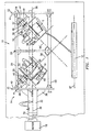
- FIG. 1 illustrates an apparatus for coating one or more workpieces in accordance with the present invention; and
- FIG. 2 is a sectional view of a spindle and bushing arrangement used in the apparatus of FIG. 1.
- Referring now to the drawings, an
apparatus 10 for coating a workpiece, such as a vane or a blade to be used in a jet engine or an industrial turbine, is illustrated in FIG. 1. Theapparatus 10 includes asource 12 of coating material and amodular fixture 14 for holding one ormore workpieces 16 to be coated. Theapparatus 10 further includes means (not shown) for heating the coating material to form a cloud of coating material and amotor 18 for rotating themodular fixture 14. - The
modular fixture 14 allows the workpiece(s) 16 to be simultaneously moved about three axes during the coating operation while the workpiece(s) 16 are maintained in a fixed horizontal and vertical position with respect to thesource 12. In particular, thefixture 14 maintains eachworkpiece 16, particularly its center, at a fixed distance from thecoating material source 12. In a preferred arrangement of the present invention, the center of theworkpiece 16 is located at the point where a first axis ofrotation 36 intersects a second axis ofrotation 56 or 56' to be discussed herein after. Thefixture 14 of the present invention is different from other fixtures used in coating apparatuses which did not allow the workpiece(s) being coated to stay in a fixed horizontal and vertical position with respect to the source of coating material. As a result, these earlier fixtures did not optimize a coating formed on the workpiece with minimized likelihood of fracture or cracking. - The
modular fixture 14 is a cage formed by afirst end plate 20, asecond end plate 22, acentral support element 24, and a plurality of axially extendingsupport bars 26. The axially extendingsupport bars 26 each extend parallel to alongitudinal axis 28 of thefixture 14. - Attached to a
first surface 30 of thefirst end plate 20 is astub shaft 32. Thestub shaft 32 is joined to themotor 18 by amating shaft member 34 so that themotor 18 rotates the modular fixture about afirst axis 36 which is coincident with thelongitudinal axis 28 ofthefixture 14 and which in the illustrated embodiment is parallel to theaxis 27 of thesource 12 of coating material. Thestub shaft 32 may be joined to thefirst end plate 20 using any suitable means known in theart Supports 38 may be welded tothefirst end plate 20 and to thestub shaft 32 to help maintain thestub shaft 32 substantially parallel to a preferred axis such as thelongitudinal axis 28. - Attached to a
second surface 40 of thefirst end plate 20 byflange 41 is anarm 42. Thearm 42 extends at an angle, preferably 45 degrees, with respect to thelongitudinal axis 28 of thefixture 14. Asimilar arm 42 is attached to aninner surface 44 of thesecond end plate 22. - Referring now to both FIGS. 1 and 2, a bushing 46 is incorporated intoeach of the
arms 42. Eachbushing 46 has acentral bore 48. Eachworkpiece 16 to be coated is secured to aspindle 50. Any suitable means known in the art may be used to secure theworkpiece 16 to thespindle 50. Preferably, aholder 52 is provided at one end of thespindle 50. Theholder 52 may comprise any suitable means known in the art for holding a workpiece during a coating operation. Preferably, theholder 52 is a holder such as that shown in U.S. Patent No. 5,849,359 to Burns et al., which is incorporated by reference herein. The opposite end of thespindle 50 has ahead 54 whose diameter is greater than the diameter of thebore 48. - The
spindle 50 and thebushing 46 on a first one of the arms define a second axis ofrotation 56 at an angle to the first axis ofrotation 36, while thespindle 50 and bushing 46 on the other arm define a third axis of rotation 56' at an angle to the first axis ofrotation 36. Preferably, the second and third axes are substantially perpendicular to each other. As a result of this construction, eachrespective workpiece 16 is capable of rotating about one of theaxes 56 and 56', while it is simultaneously being rotated about theaxis 36. Rotation of theworkpiece 16 about theaxis 56 or 56' is caused by gravity and friction. When the workpiece is a blade or a vane having anairfoil portion 58 with a leadingedge 60, atrailing edge 62, and a centrallongitudinal axis 64, the vane or blade will tumble or rotate about theaxis 56 or 56' leading edge over trailing edge on the centrallongitudinal axis 64. - Certain workpieces to be coated, such as blade and vanes for jet engines and industrial turbines, have
surfaces 66 and 68, such as platforms or shrouds, which extend substantially perpendicular to thelongitudinal axis 64 of anairfoil portion 58. In the past, it has been difficult to properly and consistently coat these substantially perpendicular surfaces. Due to the configuration of themodular fixture 14, namely, the rotation about theaxis 36 and the orientation of thearms 42, theworkpieces 16 will move or tilt through a nominal range of motion of preferably +45 degrees to -45 degrees with respect to the axis ofrotation 36 and with respect to thecoating source 12. As a result, a coating can be applied to thesurfaces 66 and 68 which are less likely to spall prematurely. Depending on the angle of thearm 42, the range of tilting motion could be greater than or less than +45 degrees to -45 degrees. - The
fixture 14 provides numerous advantages. First, it holds a workpiece orworkpieces 16 at a fixed distance from thesource 12 of coating material. Second, it holds eachworkpiece 16 at a fixed horizontal and vertical location with respect to thesource 12 of coating material. Third, it allows eachworkpiece 16 to be simultaneously manipulated about multiple axes while holding theworkpiece 16 at said fixed horizontal and vertical position within thecoating apparatus 10. Fourth, eachworkpiece 16 is repeatedly tilted through a range of motion of +45 degrees to - 45 degrees with respect to thelongitudinal axis 28 of thefixture 14. As a result of these advantages, the coating apparatus of the present invention more readily enables application of a close-to-uniform coating thickness and excellent airfoil and platform coating structure for vanes and blades. Such coatings do not erode as fast as coating produced using other systems. Further, the apparatus of the present invention provides the ability to coat multiple workpieces with each cycle. The fact that thefixture 14 is modular facilitates extremely fast part change overtimes, typically less than 60 seconds. - In operation, a
source 12 of coating material is provided within theapparatus 10. Thefixture 14 with one ormore workpieces 16 to be coated is placed into the coating apparatus and rotated about itslongitudinal axis 28. This in turn causes eachworkpiece 16 to rotate about theaxis 36 which is coincident with theaxis 28. Additionally, it causes each workpiece 16 to simultaneously rotate about a second axis at an angle to thefirst axis 36. Still further, it causes each workpiece 16 to tilt through a range of motion preferably from +45 degrees to-45 degrees with respect to thefirst axis 36 as the workpiece rotates about the first and second axes. While thefixture 14 and the workpieces are being rotated, the coating material in thesource 12 is vaporized. Any suitable technique known in the art, such as electron beam physical vapor deposition, cathodic arc vaporization, or the like, may be used to created the vaporized coating material. - It is apparent that there has been described above a multiple axis tumbler coating apparatus which fully satisfies the objects, means, and advantages set forth hereinbefore. While the present invention has been described in the context of specific embodiments thereof, other alternatives, modifications, and variations will become apparent to those skilled in the art having read the foregoing description. Accordingly, it is intended to embrace those alternatives, modifications, and variations as fall within the broad scope of the appended claims.
Claims (15)
- An apparatus (10) for coating a workpiece comprising a device for simultaneously manipulating said workpiece about multiple axes (36,56) while holding acenter of the workpiece at a fixed horizontal and vertical location with respect to a source (12) of coating material.
- An apparatus according to claim 1 , wherein said workpiece has a first portion with a leading edge (60) and a trailing edge (62) and said device including means for rotating said leading edge (60) over said trailing edge (62) about said center during a coating operation.
- An apparatus according to claim 1 or 2, wherein said workpiece comprises a part having an airfoil portion (58) with a longitudinal axis (64) and first and second surfaces (66,68) both perpendicular to said longitudinal axis, and said device comprising means for tilting said part so that said first and second surfaces (66,68) move through a range of motion from-45 degrees to +45 degrees with respect to said coating source (12) during a coating operation.
- An apparatus according to claim 1, 2 or 3, wherein said device includes means for rotating said part about a first axis of rotation (36) parallel to an axis (27) of said coating source; means for rotating said part about a second axis (56) at an angle to said first axis (36) while said part is being rotated about said first axis (36); and means for tilting said part through a range of motion from about +45 degrees to -45 degrees with respect to said first axis (36) while said part is being rotated about said first and second axes (36,56).
- An apparatus according to any preceding claim, wherein said device comprises a modular fixture (14) having an end plate (20) and a stub shaft (32) attached to a first surface (30) of said end plate (20) for defining a first axis of rotation (36) for a part to be placed within the modular fixture (14) and wherein said modular fixture (14) further includes means for supporting said part so that said part can rotate about a second axis (56) at an angle to the first axis (36) and can be tilted through a range of about-45 degrees to +45 degrees with respect to said first axis (36) while said part is being rotated about said first axis (36).
- An apparatus according to claim 5, wherein said part supporting means comprises a first arm (42) positioned at an angle with respect to a second surface (40) of said end plate (20), a first bushing (46) incorporated into said first arm (42) and having a first bore (48), and a first spindle (50) having a portion which passes through said first bore (48) and which cooperates with said first bushing (46) to allow said part to rotate about said second axis (56) and a part holder (52) secured to an end of said spindle (50).
- An apparatus according to claim 6, wherein said device includes a second part supporting means which comprises a second end plate (22), a second arm (42) positioned at an angle with respect to a surface (44) of said second end plate (22), a second bushing (46) incorporated into said second arm (42) and having a second bore (48), and a second spindle (50) having a portion which passes through said second bore (48) and which cooperates with said second bushing (46) to allow said second part to rotate about a fourth axis (56') at an angle to said first axis (36).
- A modular fixture (14) for coating a plurality of workpieces comprising:a first end plate (20);a second end plate (22) spaced from said first end plate (20);a longitudinal axis (28) extending from said first end plate (20) to said second end plate (22);means for enabling said fixture to be rotated about a first axis (36) parallel to said longitudinal axis;a first arm (42) attached to said first end plate (20) and first rotation means incorporated within said first arm (42) for allowing a first part to rotate about a second axis (56) at an angle relative to said first axis (36) and for allowing said first part to tilt relative to said first axis (36) while said first part is rotating about said second axis (56); anda second arm (42) attached to said second end plate (22) and second rotation means incorporated within said second arm (42) for allowing a second part to rotate about a third axis (56') at an angle relative to said first axis (36) and for allowing said second part to tilt relative to said first axis (36) while said second part is rotating about said third axis (56').
- A modular fixture according to claim 8, wherein said first rotation means comprises a first bushing (46) within said first arm (42) and a first spindle (50) having a first portion for cooperating with said first bushing (46) and wherein said second rotation means comprises a second bushing (46) within said second (42) arm and a second spindle (50) having a second portion for cooperating with said second bushing (46).
- A modular fixture according to claim 9, further comprising a first part holder (52) secured to an end of said first spindle (50) and a second part holder (52) secured to an end of said second spindle (50), and wherein said second axis (56) and said third axis (56') are substantially perpendicular to each other.
- A modular fixture according to any of claims 8 to 10, wherein said rotation enabling means comprises a stub shaft (32) attached to a surface (30) of said first end plate (20) for allowing said modular fixture to be rotated about said first axis (36), and further comprising a plurality of rod members (26) extending from said first end plate (20) to said second end plate (22).
- A process for coating a workpiece comprising the steps of:providing a source (12) of coating material;providing a fixture (14) for supporting said workpiece at a fixed distance with respect to said coating material source (12);rotating said workpiece about a first axis (36) while maintaining a center of said workpiece at said fixed distance from said coating material source (12);rotating said workpiece about a second axis (56) at an angle to said first axis (36) while rotating said workpiece about said first axis (36);tilting said workpiece through a range of motion with respect to said first axis (36) while rotating said workpiece about said first and second axes (36, 56); andforming a coating material vapor.
- A process according to claim 12, wherein said workpiece has a longitudinal axis (64) and two surfaces (66, 68) substantially perpendicular to said workpiece longitudinal axis (64) and said step of rotating said workpiece about said first axis (36) and said tilting step allows said substantially perpendicular surfaces (66, 68) to be coated; and wherein said workpiece has an airfoil portion (58) with a leading edge (60) and a trailing edge (62) and said step of rotating said workpiece about said second axis (56) causes said workpiece to tumble leading edge (60) over trailing edge (62).
- A process according to claim 12 or 13, wherein said workpiece comprises a vane having an airfoil portion (58) with a leading edge (60), a trailing edge (62),and a longitudinal axis (64) and two platform surfaces (66,68) substantially perpendicular to said longitudinal axis (64) and said rotating steps and said tilting steps allowing said airfoil portion (58) and said platform surfaces (66,68) to be coated.
- A process according to claim 12 or 13, wherein said workpiece comprises a blade having an airfoil portion (58) with a leading edge (60), a trailing edge (62), and a longitudinal axis (64) and two shroud surfaces (66,68) substantially perpendicular to said longitudinal axis (64) and said rotating steps and said tilting steps allowing said airfoil portion (58) and said shroud surfaces (66,68) to be coated.
Priority Applications (1)
| Application Number | Priority Date | Filing Date | Title |
|---|---|---|---|
| EP11164105A EP2343396B1 (en) | 2002-10-07 | 2003-10-06 | Multiple axis tumbler coating apparatus |
Applications Claiming Priority (2)
| Application Number | Priority Date | Filing Date | Title |
|---|---|---|---|
| US10/266,052 US7754016B2 (en) | 2002-10-07 | 2002-10-07 | Multiple axis tumbler coating apparatus |
| US266052 | 2002-10-07 |
Related Child Applications (1)
| Application Number | Title | Priority Date | Filing Date |
|---|---|---|---|
| EP11164105A Division EP2343396B1 (en) | 2002-10-07 | 2003-10-06 | Multiple axis tumbler coating apparatus |
Publications (2)
| Publication Number | Publication Date |
|---|---|
| EP1413643A2 true EP1413643A2 (en) | 2004-04-28 |
| EP1413643A3 EP1413643A3 (en) | 2006-05-17 |
Family
ID=32042588
Family Applications (2)
| Application Number | Title | Priority Date | Filing Date |
|---|---|---|---|
| EP03256288A Withdrawn EP1413643A3 (en) | 2002-10-07 | 2003-10-06 | Multiple axis tumbler coating apparatus |
| EP11164105A Expired - Lifetime EP2343396B1 (en) | 2002-10-07 | 2003-10-06 | Multiple axis tumbler coating apparatus |
Family Applications After (1)
| Application Number | Title | Priority Date | Filing Date |
|---|---|---|---|
| EP11164105A Expired - Lifetime EP2343396B1 (en) | 2002-10-07 | 2003-10-06 | Multiple axis tumbler coating apparatus |
Country Status (4)
| Country | Link |
|---|---|
| US (2) | US7754016B2 (en) |
| EP (2) | EP1413643A3 (en) |
| JP (1) | JP4063752B2 (en) |
| SG (1) | SG121801A1 (en) |
Families Citing this family (11)
| Publication number | Priority date | Publication date | Assignee | Title |
|---|---|---|---|---|
| US6923868B2 (en) * | 2003-09-23 | 2005-08-02 | Gba S.A. | Installation for electron-ray coatication of coatings |
| DE102005010005A1 (en) * | 2005-03-04 | 2006-12-28 | Nunner, Dieter | Apparatus and method for coating small parts |
| US7837843B2 (en) * | 2005-07-12 | 2010-11-23 | Praxair S.T. Technology, Inc. | Fixture for use in a coating operation |
| DE502005006824D1 (en) * | 2005-09-12 | 2009-04-23 | Siemens Ag | Method for coating a turbine blade |
| EP1806425A1 (en) * | 2006-01-09 | 2007-07-11 | Siemens Aktiengesellschaft | Method and apparatus for coating a substrate |
| US20100078308A1 (en) * | 2008-09-30 | 2010-04-01 | General Electric Company | Process for depositing a coating on a blisk |
| WO2011025522A1 (en) * | 2009-08-26 | 2011-03-03 | Molecular Imprints, Inc. | Functional nanoparticles |
| US9109289B2 (en) * | 2011-06-27 | 2015-08-18 | United Technologies Corporation | Manipulator for coating application |
| RU2693227C1 (en) * | 2018-04-25 | 2019-07-01 | Общество с ограниченной ответственностью Научно-производственное предприятие "Уралавиаспецтехнология" | Method of applying erosion-resistant coatings on blisk blizzards of gas turbine engine of titanium alloys |
| CN113621929B (en) | 2020-05-08 | 2023-04-11 | 武汉光谷创元电子有限公司 | Microwave device manufacturing apparatus and method |
| CN117385326A (en) * | 2023-12-11 | 2024-01-12 | 成都晨发泰达航空科技股份有限公司 | Rotating device for EB-PVD thermal barrier coating and blade coating method |
Citations (1)
| Publication number | Priority date | Publication date | Assignee | Title |
|---|---|---|---|---|
| US5558909A (en) * | 1996-01-17 | 1996-09-24 | Textron Automotive Interiors, Inc. | Apparatus and method for vacuum-metallizing articles with significant deposition onto three-dimensional surfaces |
Family Cites Families (11)
| Publication number | Priority date | Publication date | Assignee | Title |
|---|---|---|---|---|
| JPS5247530A (en) | 1975-10-14 | 1977-04-15 | Pioneer Electronic Corp | Vaporisation apparatus |
| US4485759A (en) * | 1983-01-19 | 1984-12-04 | Multi-Arc Vacuum Systems Inc. | Planetary substrate support apparatus for vapor vacuum deposition coating |
| JPS62149870A (en) | 1985-12-24 | 1987-07-03 | Matsushita Electric Ind Co Ltd | Vapor deposition device |
| JPH0820126B2 (en) | 1990-04-28 | 1996-03-04 | ダイキン工業株式会社 | Refrigeration equipment |
| US5803971A (en) * | 1997-01-13 | 1998-09-08 | United Technologies Corporation | Modular coating fixture |
| US6083322A (en) | 1997-03-06 | 2000-07-04 | United Technologies Corporation | Modular coating fixture |
| US5849359A (en) * | 1997-07-17 | 1998-12-15 | United Technologies Corporation | Variable tilting tumbler vacuum coating apparatus |
| US6206065B1 (en) * | 1997-07-30 | 2001-03-27 | The Governors Of The University Of Alberta | Glancing angle deposition of thin films |
| US5876860A (en) * | 1997-12-09 | 1999-03-02 | N.V. Interturbine | Thermal barrier coating ceramic structure |
| US5997947A (en) * | 1998-04-29 | 1999-12-07 | United Technologies Corporation | Rotisserie fixture for coating airfoils |
| DE10116365C1 (en) | 2001-04-02 | 2002-09-05 | Ald Vacuum Techn Ag | Supporting arm used for coating turbine blades comprises a holding device having a hollow shaft connected at its front end to a part to be coated |
-
2002
- 2002-10-07 US US10/266,052 patent/US7754016B2/en active Active
-
2003
- 2003-10-02 SG SG200305759A patent/SG121801A1/en unknown
- 2003-10-06 EP EP03256288A patent/EP1413643A3/en not_active Withdrawn
- 2003-10-06 EP EP11164105A patent/EP2343396B1/en not_active Expired - Lifetime
- 2003-10-07 JP JP2003348357A patent/JP4063752B2/en not_active Expired - Fee Related
-
2004
- 2004-08-09 US US10/914,904 patent/US7311783B2/en not_active Expired - Lifetime
Patent Citations (1)
| Publication number | Priority date | Publication date | Assignee | Title |
|---|---|---|---|---|
| US5558909A (en) * | 1996-01-17 | 1996-09-24 | Textron Automotive Interiors, Inc. | Apparatus and method for vacuum-metallizing articles with significant deposition onto three-dimensional surfaces |
Also Published As
| Publication number | Publication date |
|---|---|
| SG121801A1 (en) | 2006-05-26 |
| US20050005852A1 (en) | 2005-01-13 |
| EP2343396B1 (en) | 2012-08-22 |
| US7311783B2 (en) | 2007-12-25 |
| JP4063752B2 (en) | 2008-03-19 |
| US20040065262A1 (en) | 2004-04-08 |
| EP2343396A1 (en) | 2011-07-13 |
| US7754016B2 (en) | 2010-07-13 |
| JP2004131847A (en) | 2004-04-30 |
| EP1413643A3 (en) | 2006-05-17 |
Similar Documents
| Publication | Publication Date | Title |
|---|---|---|
| EP2343396B1 (en) | Multiple axis tumbler coating apparatus | |
| US5849359A (en) | Variable tilting tumbler vacuum coating apparatus | |
| JP3290620B2 (en) | Method and apparatus for coating a workpiece | |
| EP1505168B1 (en) | Turbine element repair | |
| US7014533B2 (en) | Method for smoothing the surface of a gas turbine blade | |
| US7837843B2 (en) | Fixture for use in a coating operation | |
| JP4162394B2 (en) | Method for protecting the surface of a nickel-based article with a corrosion-resistant aluminum alloy layer | |
| KR100367802B1 (en) | How to form a protective coating | |
| JP3288332B2 (en) | Fixture | |
| US20110052406A1 (en) | Airfoil and process for depositing an erosion-resistant coating on the airfoil | |
| US20060222776A1 (en) | Environment-resistant platinum aluminide coatings, and methods of applying the same onto turbine components | |
| CA2858093C (en) | Tooling fixture assembly for use in a coating operation | |
| CN1372502A (en) | Method and device for treating the surface of part | |
| JP4981828B2 (en) | Method of forming HVOF sprayed coating layer and turbine member holding device | |
| JP2009527647A (en) | Coating using carbon nitride and products coated with carbon nitride | |
| CN102562305A (en) | Component and methods of fabricating and coating a component | |
| JP2012193450A (en) | Component manipulator for dynamic positioning of substrate, coating method and use of component manipulator | |
| JP4866860B2 (en) | Addition of high temperature resistance to internal combustion engine parts | |
| EP2468918A2 (en) | Coating deposition apparatus and method therefor | |
| CN110760809A (en) | Clamping device for preparing thermal barrier coating by electron beam physical vapor deposition | |
| JP2001226758A (en) | Turbine blade and gas turbine member | |
| US7144302B2 (en) | Method for smoothing the surface of a gas turbine blade | |
| EP2236640A2 (en) | Multi-component coating deposition | |
| CA2373591C (en) | A process for applying a heat shielding coating system on a metallic substrate | |
| JP2004308009A (en) | Environment resistant coating and bond coating method for turbine channel parts |
Legal Events
| Date | Code | Title | Description |
|---|---|---|---|
| PUAI | Public reference made under article 153(3) epc to a published international application that has entered the european phase |
Free format text: ORIGINAL CODE: 0009012 |
|
| AK | Designated contracting states |
Kind code of ref document: A2 Designated state(s): AT BE BG CH CY CZ DE DK EE ES FI FR GB GR HU IE IT LI LU MC NL PT RO SE SI SK TR |
|
| AX | Request for extension of the european patent |
Extension state: AL LT LV MK |
|
| PUAL | Search report despatched |
Free format text: ORIGINAL CODE: 0009013 |
|
| AK | Designated contracting states |
Kind code of ref document: A3 Designated state(s): AT BE BG CH CY CZ DE DK EE ES FI FR GB GR HU IE IT LI LU MC NL PT RO SE SI SK TR |
|
| AX | Request for extension of the european patent |
Extension state: AL LT LV MK |
|
| 17P | Request for examination filed |
Effective date: 20060703 |
|
| AKX | Designation fees paid |
Designated state(s): AT BE BG CH CY CZ DE DK EE ES FI FR GB GR HU IE IT LI LU MC NL PT RO SE SI SK TR |
|
| 17Q | First examination report despatched |
Effective date: 20090424 |
|
| STAA | Information on the status of an ep patent application or granted ep patent |
Free format text: STATUS: THE APPLICATION IS DEEMED TO BE WITHDRAWN |
|
| 18D | Application deemed to be withdrawn |
Effective date: 20150501 |