EP1413498B1 - Four-wheel drive vehicle - Google Patents
Four-wheel drive vehicle Download PDFInfo
- Publication number
- EP1413498B1 EP1413498B1 EP03023896A EP03023896A EP1413498B1 EP 1413498 B1 EP1413498 B1 EP 1413498B1 EP 03023896 A EP03023896 A EP 03023896A EP 03023896 A EP03023896 A EP 03023896A EP 1413498 B1 EP1413498 B1 EP 1413498B1
- Authority
- EP
- European Patent Office
- Prior art keywords
- hydraulic
- vehicle
- axles
- frame
- transaxle apparatus
- Prior art date
- Legal status (The legal status is an assumption and is not a legal conclusion. Google has not performed a legal analysis and makes no representation as to the accuracy of the status listed.)
- Expired - Lifetime
Links
- 239000012530 fluid Substances 0.000 claims description 59
- 238000006073 displacement reaction Methods 0.000 claims description 31
- 230000009977 dual effect Effects 0.000 claims 5
- 239000003921 oil Substances 0.000 description 26
- 210000003734 kidney Anatomy 0.000 description 17
- 230000008878 coupling Effects 0.000 description 12
- 238000010168 coupling process Methods 0.000 description 12
- 238000005859 coupling reaction Methods 0.000 description 12
- 244000309464 bull Species 0.000 description 10
- 238000005452 bending Methods 0.000 description 8
- 230000005540 biological transmission Effects 0.000 description 8
- 239000010720 hydraulic oil Substances 0.000 description 7
- 238000010276 construction Methods 0.000 description 6
- 238000001816 cooling Methods 0.000 description 6
- 230000008859 change Effects 0.000 description 5
- 230000007246 mechanism Effects 0.000 description 5
- 238000004891 communication Methods 0.000 description 3
- 238000010586 diagram Methods 0.000 description 3
- 230000008901 benefit Effects 0.000 description 2
- 230000000694 effects Effects 0.000 description 2
- 230000002708 enhancing effect Effects 0.000 description 2
- 230000002706 hydrostatic effect Effects 0.000 description 2
- 230000033001 locomotion Effects 0.000 description 2
- 239000000463 material Substances 0.000 description 2
- 230000007935 neutral effect Effects 0.000 description 2
- 239000012809 cooling fluid Substances 0.000 description 1
- 238000001514 detection method Methods 0.000 description 1
- 239000010687 lubricating oil Substances 0.000 description 1
- 230000009347 mechanical transmission Effects 0.000 description 1
- 230000009467 reduction Effects 0.000 description 1
- 230000002441 reversible effect Effects 0.000 description 1
- 238000007789 sealing Methods 0.000 description 1
Images


Classifications
-
- B—PERFORMING OPERATIONS; TRANSPORTING
- B60—VEHICLES IN GENERAL
- B60K—ARRANGEMENT OR MOUNTING OF PROPULSION UNITS OR OF TRANSMISSIONS IN VEHICLES; ARRANGEMENT OR MOUNTING OF PLURAL DIVERSE PRIME-MOVERS IN VEHICLES; AUXILIARY DRIVES FOR VEHICLES; INSTRUMENTATION OR DASHBOARDS FOR VEHICLES; ARRANGEMENTS IN CONNECTION WITH COOLING, AIR INTAKE, GAS EXHAUST OR FUEL SUPPLY OF PROPULSION UNITS IN VEHICLES
- B60K17/00—Arrangement or mounting of transmissions in vehicles
- B60K17/34—Arrangement or mounting of transmissions in vehicles for driving both front and rear wheels, e.g. four wheel drive vehicles
- B60K17/356—Arrangement or mounting of transmissions in vehicles for driving both front and rear wheels, e.g. four wheel drive vehicles having fluid or electric motor, for driving one or more wheels
-
- A—HUMAN NECESSITIES
- A01—AGRICULTURE; FORESTRY; ANIMAL HUSBANDRY; HUNTING; TRAPPING; FISHING
- A01D—HARVESTING; MOWING
- A01D34/00—Mowers; Mowing apparatus of harvesters
- A01D34/01—Mowers; Mowing apparatus of harvesters characterised by features relating to the type of cutting apparatus
- A01D34/412—Mowers; Mowing apparatus of harvesters characterised by features relating to the type of cutting apparatus having rotating cutters
- A01D34/63—Mowers; Mowing apparatus of harvesters characterised by features relating to the type of cutting apparatus having rotating cutters having cutters rotating about a vertical axis
-
- A—HUMAN NECESSITIES
- A01—AGRICULTURE; FORESTRY; ANIMAL HUSBANDRY; HUNTING; TRAPPING; FISHING
- A01D—HARVESTING; MOWING
- A01D69/00—Driving mechanisms or parts thereof for harvesters or mowers
- A01D69/03—Driving mechanisms or parts thereof for harvesters or mowers fluid
-
- B—PERFORMING OPERATIONS; TRANSPORTING
- B60—VEHICLES IN GENERAL
- B60K—ARRANGEMENT OR MOUNTING OF PROPULSION UNITS OR OF TRANSMISSIONS IN VEHICLES; ARRANGEMENT OR MOUNTING OF PLURAL DIVERSE PRIME-MOVERS IN VEHICLES; AUXILIARY DRIVES FOR VEHICLES; INSTRUMENTATION OR DASHBOARDS FOR VEHICLES; ARRANGEMENTS IN CONNECTION WITH COOLING, AIR INTAKE, GAS EXHAUST OR FUEL SUPPLY OF PROPULSION UNITS IN VEHICLES
- B60K17/00—Arrangement or mounting of transmissions in vehicles
- B60K17/04—Arrangement or mounting of transmissions in vehicles characterised by arrangement, location, or kind of gearing
- B60K17/10—Arrangement or mounting of transmissions in vehicles characterised by arrangement, location, or kind of gearing of fluid gearing
- B60K17/105—Units comprising at least a part of the gearing and a torque-transmitting axle, e.g. transaxles
-
- B—PERFORMING OPERATIONS; TRANSPORTING
- B60—VEHICLES IN GENERAL
- B60K—ARRANGEMENT OR MOUNTING OF PROPULSION UNITS OR OF TRANSMISSIONS IN VEHICLES; ARRANGEMENT OR MOUNTING OF PLURAL DIVERSE PRIME-MOVERS IN VEHICLES; AUXILIARY DRIVES FOR VEHICLES; INSTRUMENTATION OR DASHBOARDS FOR VEHICLES; ARRANGEMENTS IN CONNECTION WITH COOLING, AIR INTAKE, GAS EXHAUST OR FUEL SUPPLY OF PROPULSION UNITS IN VEHICLES
- B60K17/00—Arrangement or mounting of transmissions in vehicles
- B60K17/34—Arrangement or mounting of transmissions in vehicles for driving both front and rear wheels, e.g. four wheel drive vehicles
- B60K17/358—Arrangement or mounting of transmissions in vehicles for driving both front and rear wheels, e.g. four wheel drive vehicles all driven wheels being steerable
-
- B—PERFORMING OPERATIONS; TRANSPORTING
- B62—LAND VEHICLES FOR TRAVELLING OTHERWISE THAN ON RAILS
- B62D—MOTOR VEHICLES; TRAILERS
- B62D12/00—Steering specially adapted for vehicles operating in tandem or having pivotally connected frames
-
- F—MECHANICAL ENGINEERING; LIGHTING; HEATING; WEAPONS; BLASTING
- F16—ENGINEERING ELEMENTS AND UNITS; GENERAL MEASURES FOR PRODUCING AND MAINTAINING EFFECTIVE FUNCTIONING OF MACHINES OR INSTALLATIONS; THERMAL INSULATION IN GENERAL
- F16H—GEARING
- F16H61/00—Control functions within control units of change-speed- or reversing-gearings for conveying rotary motion ; Control of exclusively fluid gearing, friction gearing, gearings with endless flexible members or other particular types of gearing
- F16H61/38—Control of exclusively fluid gearing
- F16H61/40—Control of exclusively fluid gearing hydrostatic
- F16H61/42—Control of exclusively fluid gearing hydrostatic involving adjustment of a pump or motor with adjustable output or capacity
- F16H61/423—Motor capacity control by fluid pressure control means
-
- F—MECHANICAL ENGINEERING; LIGHTING; HEATING; WEAPONS; BLASTING
- F16—ENGINEERING ELEMENTS AND UNITS; GENERAL MEASURES FOR PRODUCING AND MAINTAINING EFFECTIVE FUNCTIONING OF MACHINES OR INSTALLATIONS; THERMAL INSULATION IN GENERAL
- F16H—GEARING
- F16H61/00—Control functions within control units of change-speed- or reversing-gearings for conveying rotary motion ; Control of exclusively fluid gearing, friction gearing, gearings with endless flexible members or other particular types of gearing
- F16H61/38—Control of exclusively fluid gearing
- F16H61/40—Control of exclusively fluid gearing hydrostatic
- F16H61/44—Control of exclusively fluid gearing hydrostatic with more than one pump or motor in operation
- F16H61/444—Control of exclusively fluid gearing hydrostatic with more than one pump or motor in operation by changing the number of pump or motor units in operation
-
- F—MECHANICAL ENGINEERING; LIGHTING; HEATING; WEAPONS; BLASTING
- F16—ENGINEERING ELEMENTS AND UNITS; GENERAL MEASURES FOR PRODUCING AND MAINTAINING EFFECTIVE FUNCTIONING OF MACHINES OR INSTALLATIONS; THERMAL INSULATION IN GENERAL
- F16H—GEARING
- F16H61/00—Control functions within control units of change-speed- or reversing-gearings for conveying rotary motion ; Control of exclusively fluid gearing, friction gearing, gearings with endless flexible members or other particular types of gearing
- F16H61/38—Control of exclusively fluid gearing
- F16H61/40—Control of exclusively fluid gearing hydrostatic
- F16H61/44—Control of exclusively fluid gearing hydrostatic with more than one pump or motor in operation
- F16H61/456—Control of the balance of torque or speed between pumps or motors
-
- A—HUMAN NECESSITIES
- A01—AGRICULTURE; FORESTRY; ANIMAL HUSBANDRY; HUNTING; TRAPPING; FISHING
- A01D—HARVESTING; MOWING
- A01D2101/00—Lawn-mowers
-
- B—PERFORMING OPERATIONS; TRANSPORTING
- B60—VEHICLES IN GENERAL
- B60Y—INDEXING SCHEME RELATING TO ASPECTS CROSS-CUTTING VEHICLE TECHNOLOGY
- B60Y2200/00—Type of vehicle
- B60Y2200/20—Off-Road Vehicles
- B60Y2200/22—Agricultural vehicles
- B60Y2200/223—Ridable lawn mowers
-
- F—MECHANICAL ENGINEERING; LIGHTING; HEATING; WEAPONS; BLASTING
- F16—ENGINEERING ELEMENTS AND UNITS; GENERAL MEASURES FOR PRODUCING AND MAINTAINING EFFECTIVE FUNCTIONING OF MACHINES OR INSTALLATIONS; THERMAL INSULATION IN GENERAL
- F16H—GEARING
- F16H39/00—Rotary fluid gearing using pumps and motors of the volumetric type, i.e. passing a predetermined volume of fluid per revolution
- F16H39/04—Rotary fluid gearing using pumps and motors of the volumetric type, i.e. passing a predetermined volume of fluid per revolution with liquid motor and pump combined in one unit
- F16H39/06—Rotary fluid gearing using pumps and motors of the volumetric type, i.e. passing a predetermined volume of fluid per revolution with liquid motor and pump combined in one unit pump and motor being of the same type
- F16H39/08—Rotary fluid gearing using pumps and motors of the volumetric type, i.e. passing a predetermined volume of fluid per revolution with liquid motor and pump combined in one unit pump and motor being of the same type each with one main shaft and provided with pistons reciprocating in cylinders
- F16H39/10—Rotary fluid gearing using pumps and motors of the volumetric type, i.e. passing a predetermined volume of fluid per revolution with liquid motor and pump combined in one unit pump and motor being of the same type each with one main shaft and provided with pistons reciprocating in cylinders with cylinders arranged around, and parallel or approximately parallel to the main axis of the gearing
- F16H39/14—Rotary fluid gearing using pumps and motors of the volumetric type, i.e. passing a predetermined volume of fluid per revolution with liquid motor and pump combined in one unit pump and motor being of the same type each with one main shaft and provided with pistons reciprocating in cylinders with cylinders arranged around, and parallel or approximately parallel to the main axis of the gearing with cylinders carried in rotary cylinder blocks or cylinder-bearing members
-
- F—MECHANICAL ENGINEERING; LIGHTING; HEATING; WEAPONS; BLASTING
- F16—ENGINEERING ELEMENTS AND UNITS; GENERAL MEASURES FOR PRODUCING AND MAINTAINING EFFECTIVE FUNCTIONING OF MACHINES OR INSTALLATIONS; THERMAL INSULATION IN GENERAL
- F16H—GEARING
- F16H59/00—Control inputs to control units of change-speed-, or reversing-gearings for conveying rotary motion
- F16H59/50—Inputs being a function of the status of the machine, e.g. position of doors or safety belts
- F16H59/58—Inputs being a function of the status of the machine, e.g. position of doors or safety belts dependent on signals from the steering
-
- F—MECHANICAL ENGINEERING; LIGHTING; HEATING; WEAPONS; BLASTING
- F16—ENGINEERING ELEMENTS AND UNITS; GENERAL MEASURES FOR PRODUCING AND MAINTAINING EFFECTIVE FUNCTIONING OF MACHINES OR INSTALLATIONS; THERMAL INSULATION IN GENERAL
- F16H—GEARING
- F16H7/00—Gearings for conveying rotary motion by endless flexible members
- F16H7/02—Gearings for conveying rotary motion by endless flexible members with belts; with V-belts
Definitions
- the invention relates to a four-wheel-drive vehicle according the preamble portion of claim 1, particularly to a four-wheel drive articulate working vehicle such as a riding lawn mower. More particularly, it relates to a structure of a transaxle apparatus in the vehicle, and a structure for drivingly connecting front and rear transaxle apparatuses in the vehicle to each other.
- first and second frames Conventionally, there is a well-known articulate riding lawn mower with pivotally connected first and second frames so as to allow the second frame to be folded relative to the first frame around a vertical axial pivot by steering operation (i.e., manipulation of a steering wheel).
- the first frame is equipped with an engine and a transaxle apparatus supporting a first axle driven by the engine.
- the second frame is equipped with a working device such as a mover device, a driver's unit, and an axle casing supporting a freely rotatable second axle.
- a riding lawn mower provided with an Ackerman type steering system is also well known.
- the Japanese Patent Laid Open Gazette 2000-270,651 discloses an articulate four-wheeled lawn mower in which the first frame serves as a rear frame and the second frame serves as a front frame.
- the rear frame is provided with an HST (a hydrostatic transmission) for transmitting engine power to rear wheels supported by the rear frame.
- the rear frame is provided with a power take-off shaft for taking out power from a pump shaft of a hydraulic pump of the HST so as to transmit the rotation of the power take-off shaft to a mower device supported by the front frame.
- some articulate vehicles have such a feature that the first and second frames differ in length and the first and second axles are unequally distant from the pivot in correspondence of the length difference between the frames.
- Each of the above-mentioned conventional vehicles is a two-wheel drive vehicle, in which the second axle supported by the axle casing on the second frame (usually serving as a front frame) rotates freely from the engine power driving the first axle supported by the transaxle apparatus of the first frame (usually serving as a rear frame).
- the two-wheel-drive vehicle driving only rear wheels is advantageous in steering performance, however, it lacks stability when working on a slope and road ability when running on a bad road. Moreover, the vehicle mired in mud or the like is difficult to bail out.
- a four-wheel drive articulate vehicle may be provided.
- the power take-off shaft is rotated synchronously to rotation of the pump shaft so that the rotary speed of the power take-off shaft is constant as long as the rotary speed of the engine is constant, while the rotary speed of the rear wheels driven by output of the hydraulic motor is changed by speed change operation for adjusting a swash plate angle of the hydraulic pump.
- the power take-off shaft for driving the working device cannot be used as a front-wheel drive shaft simply.
- front and rear axles of the above-disclosed four-wheel-drive articulate working vehicle of the US Patent '452 are equally distant from the pivot between the front and rear frames so that the vehicle may turn smoothly without dragging any of front and rear wheels by keeping a constant relative velocity between the first and second axles whether the vehicle goes straight or turns.
- An object of the present invention is to provide a four-wheel-drive articulate working vehicle having pivotally connected first and second frames and first and second axles supported by the respective first, and second frames, the first and second axles being unequally distant from a pivot connecting the first and second frames, wherein, while four wheels on both the first and second axles of the vehicle are driven so as to enhance running efficiency, the vehicle can turn smoothly without dragging any of the four wheels.
- the four-wheel-drive articulate working vehicle has the features of claim 1 and steplessly changes a relative velocity between the first and second axles according to variation of a distance ratio between the first and second axles from the turning circle center of the vehicle while the vehicle is turning.
- the distance ratio varies according to variation of a turning angle of the vehicle (an angle between the first and second axles).
- At least one of the hydraulic motors on the respective first and second frames is a variable displacement motor, whose capacity automatically varies for changing the relative velocity between the first and second axles according to the variation of turning angle of the vehicle.
- the four-wheel-driving articulate working vehicle in which the first and second axles are unequally distant from the pivot between the first and second frames, can turn smoothly on a small circle without dragging any of front and rear wheels, and can mow a lawn evenly without damaging the lawn.
- the variation of relative velocity between the first and second axles is automatically linked with turning (bending) of the vehicle, thereby requiring an operator to do no complicated speed-changing operation.
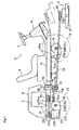
- FIG. 1 is a side view of riding lawn mower as a first embodiment of a four-wheel-drive articulate working vehicle according to the present invention, wherein front and rear axles are unequally distant from a pivot connecting front and rear frames, and a hydraulic motor in a front transaxle apparatus is variable in displacement.
- FIG. 2 is a plan view partly in section of the vehicle of FIG. 1 .
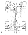
- FIG. 3 is a plan view partly in section of the vehicle when turning.
- FIG. 4 is a plan view partly in section of the vehicle, showing a fluid passage structure.
- FIG. 5 is a plan view of a front transaxle apparatus of the vehicle from which an upper housing half is removed.
- FIG. 6 is a rear view partly in section of the front transaxle apparatus.
- FIG. 7 is a sectional view in the direction of the arrows VII-VB of FIG. 5 .
- FIG. 8 is a perspective view of a motor control lever.
- FIG. 9 is a plan view of the rear transaxle apparatus from which an upper housing half is removed.
- FIG. 10 is a rear view partly in section of the rear transaxle apparatus of the present invention.
- FIG. 11 is a diagram of a hydraulic circuit for driving the vehicle, wherein the variable displacement hydraulic motor of the front transaxle apparatus and a fixed displacement hydraulic motor of a rear transaxle apparatus are fluidly connected to a common hydraulic pump in series.
- FIG. 12 is a side view of a four-wheel-drive articulate working vehicle as a second embodiment according to the present invention, wherein front and rear axles are unequally distant from a pivot connecting front and rear frames, and a hydraulic motor in a rear transaxle apparatus is variable in displacement.
- FIG. 13 is a plan view partly in section of the vehicle of FIG. 12 .
- FIG. 14 is a diagram of a hydraulic circuit for driving the vehicle, wherein the variable displacement hydraulic motor of the rear transaxle apparatus and a fixed displacement hydraulic motor of the front transaxle apparatus are fluidly connected to a common hydraulic pump in series.
- FIG. 15 is a fragmentary plan view of a modified transaxle apparatus, from which an upper housing half is removed.
- FIG. 16 is a diagram of a hydraulic circuit for a four-wheel-drive vehicle provided with a pair of front and rear hydraulic differential units, each of which includes a pair of hydraulic motors for driving respective left and right axles.
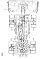
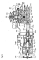
- FIGS. 1 and 2 show a working vehicle equipped at a front portion thereof with a mower device 3 serving as a working device.
- This vehicle has a front frame 11, which is longer than a rear frame 21 pivotally connected to the front frame 11.
- the front frame 11 is provided with a front transaxle apparatus 10 from which front wheel axles 12L and 12R (hereinafter, "a front wheel axle 12" is used as a generic name of the front wheel axles 12L and 12R) are extended in a transverse direction and fixed to respective front wheels 13.
- the rear frame 21 is provided with a rear transaxle apparatus 20 from which rear wheel axles 22L and 22R (hereinafter, "a rear wheel axle 22" is used as a generic name of the rear wheel axles 22L and 22R) are extended in a transverse direction and fixed to respected rear wheels 23.
- a rear wheel axle 22 is used as a generic name of the rear wheel axles 22L and 22R
- a rear end portion of the front frame 11 is horizontally rotatably coupled to a front end portion of the rear frame 21 through a coupling part 50.
- the coupling part 50 constitutes a pivot for rotation of the frames 11 and 21.
- the working vehicle including the horizontally turnable front and rear frames 11 and 21 is bendable at the intermediate portion thereof, thereby being a so-called articulate vehicle.
- the coupling part 50 is disposed at the lateral middle position of the vehicle behind the longitudinal middle position of the vehicle from which the front wheel axle 12 and the rear wheel axle 22 are equally distant. Therefore, the vehicle body is bendable at a rather rearward position than the longitudinal middle position.
- a steering column 14, a steering wheel 4, and a foot pedal are arranged in a front portion of the front frame 11, and a seat 9 is disposed behind the steering column 14, thereby constituting a driver's unit 16 on the front frame 11.
- the mower device 3 is vertically movably provided in front of the front frame 11, that is, at a downwardly forward position from the driver's unit 16.
- the mower device 3 is driven by an engine 5.
- the engine 5 covered with a bonnet 8 is disposed on the rear frame 21.
- the rear transaxle apparatus 20 is arranged under the engine 5.
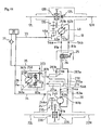
- a hydraulic pump 230 is connected to a lateral inward side of the rear transaxle apparatus 20.
- a pump input pulley 292 is fixed onto a vertical pump shaft 231 projecting upward from the hydraulic pump 230.
- a hydraulic motor 240 disposed in the rear transaxle apparatus 20 and a hydraulic motor 40 in the front transaxle apparatus 10 are fluidly connected in series to the hydraulic pump 230 through a closed fluid circuit. These parts compose a hydrostatic transmission (HST).
- HST hydrostatic transmission
- the engine 5 In front of the pump shaft 231, the engine 5 has a downwardly vertical output shaft 93 fixedly provided thereon with a first engine output pulley 94a and a second engine output pulley 94b under the first engine output pulley 94a.
- the mower device 3 serving as a working device is provided therein with mowing blades 17 and a substantially vertical drive shaft 112 for driving the mowing blades 17.
- the drive shaft 112 projects upward and is fixedly provided thereon with a mower input pulley 111.
- a vertically cylindrical pivotal connector 28 is fixed on the laterally middle front end of the rear frame 21 and not-relatively rotatably supports a vertical pivot shaft 55 therethrough.
- a pivotal connecter 18 made of a U-shaped plate is fixed on the laterally middle rear end of the front frame 11 and rotatably connected to upper and lower portions of the pivot shaft 55 projecting from the pivotal connector 28.
- the pivotal connectors 18 and 28 and the pivot shaft 55 constitute the coupling part 50 pivotally connecting the front frame 11 to the rear frame 21 so that the front and rear frames 11 and 21 are horizontally rotatable relative to each other around the pivot shaft 55.
- a lower end of the pivot shaft 55 is extended downward from the pivotal connector 18 so as to rotatably support a deceleration pulley set consisting of a first intermediate pulley 56 and a second intermediate pulley 57, which are integrally rotatable on the pivot shaft 55 through a bearing (not shown).
- a rear drive transmission belt 92 is interposed between the first engine output pulley 94a and the pump input pulley 292 behind the pulley 94a, and tensed by a first rear idle pulley 27, and a first working-device drive transmission belt 58 is interposed between the second engine output pulley 94b and the first intermediate pulley 56, and tensed by a second rear idle pulley 29.
- a second working-device drive transmission belt 59 is interposed between the second intermediate pulley 57 and the mower input pulley 111, and tensed by an idle pulley 98 rotatably provided on a vertical shaft 97 suspended from the front frame 11.
- engine output is transmitted to the pump input pulley 292 through the rear drive transmission belt 92 from the first engine output pulley 94a so as to rotate the pump shaft 231, thereby driving the front and rear wheels 13 and 23.
- the engine output is also transmitted from the second engine output pulley 94b to the mower input pulley 111 through the first belt 58, the first and second intermediate pulleys 56 and 57 and the second belt 59, thereby rotating the mowing blades 17 in the mower device 3.
- the front transaxle apparatus 10 supporting the left and right front wheel axles 12R and 12L is disposed rather leftward than the lateral middle in the front frame 11 so that the right front wheel axle 12R is longer than the left front wheel axle 12L.
- a pair of left and right collars 99a and 99b are freely rotatably provided on the right front wheel axle 12R at a substantially laterally middle position of the front frame 11.
- the second working-device drive transmission belt 59 crosses the longer right front wheel axle 12R in contact with tops of the collars 99a and 99b.
- the collars 99a and 99b freely rotate, following the driving belt 59, in opposite directions on the axle 12R, thereby preventing the belt 59 from being frictionally damaged.
- a motor control lever 65 is horizontally rotatably disposed above the front transaxle apparatus 10 fixed to the front frame 11.
- a rod 24 is pivotally interposed between the stay 52 and the motor control lever 65. Therefore, if the vehicle turns so as to change the angle between the front and rear frames 11 and 21, the rod 24 pivotally connected to the stay 52 pushes or pulls the motor control lever 65 so as to rotate the lever 65 in the longitudinal direction of the front frame 11.
- the motor control lever 65 is interlockingly connected to a movable swash plate 44 of the variable displacement hydraulic motor 40 disposed in the front transaxle apparatus 10.
- the stay 52 fixed to the pivotal connector 28 in the coupling part 50, the rod 24 pivotally supported by the stay 52, and the motor control lever 65 compose a linkage for varying a relative velocity between the front wheel axle 12 and the rear wheel axle 22.
- the vehicle is provided with an actuator (not shown) such as a hydraulic cylinder for turning the vehicle.
- the actuator bends the vehicle body with respect to the coupling part 50 as shown in FIG. 3 , i.e., horizontally relatively rotates the front frame 11 and the rear frame 21 around the vertical axis (the pivot shaft 55) of the coupling part 50, thereby turning the vehicle.
- the actuator bends the vehicle body with respect to the coupling part 50 as shown in FIG. 3 , i.e., horizontally relatively rotates the front frame 11 and the rear frame 21 around the vertical axis (the pivot shaft 55) of the coupling part 50, thereby turning the vehicle.
- the above-mentioned linkage is moved according to this bending motion of the vehicle body (variation of the angle between the front frame 11 and the rear frame 21) for turning of the vehicle, thereby steplessly changing the relative velocity between the front wheel axle 12 and the rear wheel axle 22.
- a turning circle center 101 of the vehicle is an intersection point where an extended axial line of the front wheel axle 12 intersects an extended axial line of the rear wheel axle 22. Since a ratio between a distance Fr from the turning circle center 101 to a middle point of front wheel axle 12 and a distance Rr from the turning circle center 101 to a middle point of rear wheel axle 22 varies according to variation of the turning angle of the vehicle, a relative velocity between the front wheel axle 12 and the rear wheel axle 22 needs to vary steplessly so as to realize smooth turning of the vehicle without dragging any of the wheels 13 and 23.
- the distance from the coupling part 50 (pivot shaft 55) to the front wheel axle 12 is longer than the distance from the coupling part 50 (pivot shaft 55) to the rear wheel axle22, so that the distance Fr is always shorter than the distance Rr.
- the relative velocity between the front wheel axle 12 and the rear wheel axle 22 is set to vary according to variation of the ratio of distance Fr to Rr.
- the linkage including the rod 24 moves to change the motor control lever 65 angle according to variation of the bending angle of the vehicle, whereby a tilt angle of the movable swash plate 44 varies so as to change the relative velocity between the front wheel axle 12 and the rear wheel axle 22.
- the vehicle due to the above structure, for example, the more sharply the vehicle turns, the more slowly the front wheel axle 12 rotates so that the front wheel axle 12 becomes slower than the rear wheel axle 22 so as to compensate for increase of the ratio of distance Rr to Fr, whereby the vehicle turns smoothly without drag of the wheels 13 or 23. Accordingly, the vehicle, when it is used as a riding lawn mower, prevents a lawn from being damaged by a dragged wheel.
- a concrete structure for turning of the vehicle will be discussed in later description of the front transaxle apparatus 10.
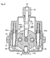
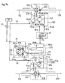
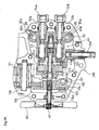
- an upper housing half 46 and a lower housing half 47 are vertically joined to each other so as to form one housing, which provides the external appearance of the front transaxle apparatus 10 and incorporates a fluid sump, the hydraulic motor 40 and others.
- the hollow interior of the housing is divided into a first chamber 10a for incorporating a counter shaft 139 with a reduction-gear train 135 thereon, a differential gear unit 120 and the front wheel axles 12L and 12R and a second chamber 10b for incorporating the hydraulic motor 40.
- Driving force of hydraulic motor 40 is transmitted to the differential gear unit 120 through the reduction-gear train 135.
- a platy center section 62 is fixed along an inside surface of the housing.
- a pair of vertical hollow dowel pins 85a are fitted into opposite end portions of the center section 62 so as to temporarily engage the center section 62 with side walls of the upper housing half 46, and then, vertical bolts 85 pierce the center section 62 and the respective dowel pins 85a and are screwed into the side walls of the upper housing half 46, thereby tightly fixing the center section 62 to the upper housing half 46.
- a vertical motor mounting surface 63m formed on the center section 62 comes to coincide at the center point thereof with the joint surface between upper and lower housing halves 46 and 47.
- a pin 87 is planted into a bottom portion of the center section 62 along the middle line of the center section 62 between the fitting bolts 85.
- the hydraulic motor 40 is integrally disposed within the front transaxle apparatus 10.
- On a vertical portion of the center section 62 is formed the vertical motor mounting surface 63m on which a cylinder block 43 is rotatably and slidably fitted.
- a plurality of pistons 42 are reciprocally movably fitted through respective biasing springs into a plurality of cylinder bores in the cylinder block 43.
- a thrust bearing 44a of a movable swash plate 44 abuts against heads of the pistons 42.
- a retainer 44b is fixedly sandwiched between the upper and lower housing halves 46 and 47 so as to slidably fit the movable swash plate 44.
- the movable swash plate 44 together with the thrust bearing 44a and the retainer 44b are penetrated by a hole through which a motor shaft 41 is allowed to pass freely.
- the motor shaft 41 has a horizontal axis located on the joint surface between the upper and lower housing halves 46 and 47.
- the motor shaft 41 axially passes through the cylinder block 43 and is not-relatively rotatably fitted with the cylinder block 43.
- the motor shaft 41 is rotatably fitted at one end thereof into center section 62.
- the motor shaft 41 is extended from the cylinder block 62 at the other end thereof through a sealed bearing 45 sandwiched between the housing halves 46 and 47 so as to serve as an output shaft of the hydraulic motor 40 for outputting rotary force to the differential gear unit 120.
- the axial piston type variable displacement hydraulic motor 40 is constructed in the front transaxle apparatus 10.
- the motor control lever 65 is connected to the movable swash plate 44 so as to vary rotary speed of the front wheel axles 12L and 12R. Therefore, the motor control lever 65 is rotated to tilt the movable swash plate 44.
- the motor control lever 65 is fixed at a basal portion thereof to an upper end of a vertical lever shaft 66 rotatably supported by an upper wall of the upper housing half 46.
- the lever shaft 66 is extended downward and rotatably fitted at the lower end thereof in the center section 62.
- a substantially horizontal plate 71 is disposed above the hydraulic motor 40 and interposed between the lever shaft 66 and the movable swash plate 44.
- the plate 71 is provided with a hole 71a toward the lever shaft 66, and with a hole 71b toward the movable swash plate 44.
- the lever shaft 66 is cranked so as to form a crank pin portion 66b, which is passed through the hole 71a in contact with an edge of the hole 71a.
- the hole 71a is elongated perpendicularly to the motor shaft 41 so that the crank pin portion 66b is movable therein according to rotation of the lever shaft 66.
- An upward projection 72 is fixed on the top of the swash plate 44 and engaged into the hole 71b of the plate 71.
- a hole 65b in a tip of the motor control lever 65, as shown in Fig. 17, is used for pivotally connecting the lever 65 to the rod 24.
- the crank pin portion 66b of the lever shaft 66 is disposed in the middle of the hole 71a so as to hold the plate 71 at the most distant position from the lever shaft 66, thereby holding the tilt angle of movable swash plate 44 (accurately, this is an angle of the surface of the movable swash plate 44 abutting against the pistons 42 from a vertical line perpendicular to the motor shaft 41) at a minimum first degree.
- the above-mentioned linkage including the rod 24 automatically, moves to rotate the motor control lever 65 and the lever shaft 66, so that the crank pin portion 66b in the hole 71a moves to one end of the hole 71a so as to pull the plate 71 toward the lever shaft 66, thereby moving the projection 72 of the movable swash plate 44 to a position drawn in phantom lines in FIG. 6 , and setting the tilt angle of movable swash plate 44 to a second degree which is larger than the first degree.
- the plate 71 moves toward the lever shaft 66 so as to increase the tilt angle of the movable swash plate 44 at the same rate.
- Increasing the tilt angle of movable swash plate 44 causes increasing the stroke of the pistons 42 in the cylinder block 43, i.e., increasing the relative capacity of the hydraulic motor 40 to the hydraulic pump 230, thereby decelerating the front wheel axle 12.
- the deceleration of the front wheel axle 12 results in reduction of the relative velocity of the front wheel axle 12 to the rear wheel axle 22 so as to compensate for increase of the above-mentioned ratio of distance Rr to Fr according to increase of the turning angle of the vehicle (the angle between the front wheel axle 12 and the rear wheel axle 22), whereby the vehicle turns smoothly without dragging any of the wheels 13 and 23.
- an arrangement for interlocking connection of the movable swash plate 44 to the pivot for bending a body of an articulate vehicle may be modified so that the stroke of pistons 42, i.e., the capacity of the hydraulic motor 40 reduces so as to increase the rotary speed of the front wheel axle 12 supported by the front transaxle apparatus 10.
- This modified arrangement is available for ensuring smooth turning of a four-wheel-drive articulate vehicle in which the distance from the pivot to the front wheel axle 12 is smaller than the distance from the same pivot to an axle of rear wheels.
- any four-wheel-drive articulate vehicle is provided with the variable relative velocity between front wheels and rear wheels so as to ensure smooth turning.
- a pair of first and second kidney ports 62a and 62b are formed in the vertical portion of the center section 62 so as to be open in the motor mounting surface 63m.
- a pair of horizontal port members 54a and 54b are fitted into the center section 62 and form therein with a horizontal first fluid passage 53a connected to the first kidney port 62a and a horizontal second fluid passage 53b connected to the second kidney port 62b, respectively.
- the port members 54a and 54b project outward from the housing so as to connect the respective fluid passages 53a and 53b to respective hydraulic fluid pipes 81a and 81b (see FIG. 4 ), thereby fluidly connecting the hydraulic motor 40 to the hydraulic pump 230 and the hydraulic motor 240 through the pipes 81a and 81b.
- the housing is provided therein with a sump of lubricating oil also serving as hydraulic oil for the HST.
- a port 46a is formed in an upper portion of the upper housing half 46 so as to bring the oil sump into communication with a later-discussed external reservoir tank 39 (see FIG. 11 ).
- a drive output gear 131 is spline-fitted onto an end of the motor shaft 41 opposite to the center section 62 so as to be rotated integrally with the motor shaft 41.
- the drive output gear 131 is integrally formed at an end thereof opposite to the hydraulic motor 40 into a brake rotor 133 which is diametrically larger than the drive output gear 131.
- One brake pad 134 is disposed between a brake cam 132 and the brake rotor 133, and another brake pad 134a between the brake rotor 133 and a wall of the housing (the housing half 46 or 47) so that the brake cam 132 is actuated to sandwich the brake rotor 133 between the brake pads 134 and 134a so as to brake the rotating motor shaft 41.
- a counter shaft 139 is arranged parallel to the motor shaft 41, an axially long small-diameter gear 137 is loosely fitted on the counter shaft 139, and a large-diameter gear 136 is not-rotatably relatively fitted onto a toothed side portion of the small diameter gear 137, thereby forming the reduction-gear train 135.
- the differential gear unit 120 comprises the bull gear 121, a pinion 123 rotatably provided on a pinion shaft 122 supported in the bull gear 121, and a pair of side gears 124 which are fixed to the respective front wheel axles 12L and 12R and laterally engaged with the pinion 123.
- the front wheel axles 12L and 12R are relatively rotatably and axially inserted at proximal ends thereof into the bull gear 121.
- the bull gear 121 receives the driving force from the motor shaft 41 through the reduction-gear train 135 and transmits it to the front wheel axles 12L and 12R through the pinion 123 and the side gears 124.
- the differential gear unit 120 is provided with a differential-lock device 125 for locking the right and left front wheel axles 12L and 12R with each other. If the vehicle is provided with an operation lever interlocking with the differential-lock device 125, and any of the running wheels is mired, the operation lever is operated to actuate the differential-lock device 125 so as to cancel the differential rotation of the front wheel axles 12L and 12R, thereby letting the stuck vehicle escape.
- an end of the motor shaft 41 opposite to the cylinder block 43 is extended outward from the housing so as to be fixedly provided thereon with a cooling fan 191 for cooling fluid collected in the front transaxle apparatus 10.
- the hydraulic motor 40 for driving the front wheel axles 12L and 12R incorporated in the front transaxle apparatus 10 is fluidly connected through the pipes 81 a and 81b to the hydraulic motor 240 for driving the rear wheel axle 22L and 22R incorporated in the rear transaxle apparatus 20.
- a housing of the rear transaxle apparatus 20 comprises a housing formed by an upper housing half 246 and a lower housing half 247 vertically separably joined to each other so as to form a hollow interior into which the hydraulic motor 240 and others are incorporated.
- a port 246a is formed in the upper portion of the upper housing half 246 so as to bring an oil sump in the housing into communication with the later-discussed external reservoir tank 39 (see FIG. 11 ).
- the housing forms bearing portions for a later-discussed motor shaft 241 along the joint surface thereof between the upper and lower housing halves 246 and 247, thereby arranging an axis of the motor shaft 241 on the joint surface between the housing halves 246 and 247.
- the rear wheel axles 22L and 22R are disposed in front of the motor shaft 241, differentially connected at proximal ends thereof to each other through a differential gear unit 220, and extended laterally outward from the respective left and right outside walls of the housing.
- the interior space of rear transaxle apparatus 20 is divided into a first chamber 20a and a second chamber 20b.
- a counter shaft 239 with gears of a reduction-gear train 235 thereon, the differential gear unit 220 and the rear wheel axles 22L and 22R are incorporated in the first chamber 20a.
- the hydraulic motor 240 is incorporated in the second chamber 20b. Driving force of the hydraulic motor 240 is transmitted to the differential gear unit 220 through the reduction-gear train 235.
- the rear transaxle apparatus 20 is substantially similar with the front transaxle apparatus 10, so that the housing formed of the upper and lower housing halves 46 and 47, major parts of the hydraulic motor 40, the gears and counter shaft 139 of the reduction-gear train 135, the differential gear unit 120, and the axles 12L and 12R, which are used for the front transaxle apparatus 10, may be also used for the rear transaxle apparatus 20 so as to serve as the housing formed of the upper and lower housing halves 246 and 247, the major parts of the hydraulic motor 240, the gears and counter shafts 239 of the reduction-gear train 235, the differential gear unit 220, and the axles 22L and 22R.
- Exclusive parts for the rear transaxle apparatus 20 are a fixed swash plate 144, which is made to be exchangeable for the movable swash plate 44, and a sealing cap which closes an opening in the upper portion of the housing so as to replace the lever shaft 66. Therefore, such common parts for the front and rear transaxle apparatuses 10 and 20 facilitate for economic product of the vehicle and for their control in stock.
- the rear transaxle apparatus 20 integrally includes the hydraulic motor 240 arranged in the second chamber 20b.
- a cylinder block 143 is rotatable and slidably disposed on a motor mounting surface formed on a vertical portion of the center section 162.
- Pistons 142 are reciprocally movably fitted through respective biasing springs into a plurality of cylinder bores in the cylinder block 143.
- a thrust bearing 144a of the fixed swash plate 144 abuts against heads of the pistons 142.
- An opening 144b is provided at the center of the fixed swash plate 144 so as to allow a motor shaft 241 to pass therethrough.
- the fixed swash plate 144 is fixedly sandwiched between the upper housing half 246 and the lower housing half 247.
- a pair of first and second kidney ports 162a and 162b are formed in the vertical portion of the center section 162 so as to be open in the motor mounting surface.
- a pair of horizontal port members 154a and 154b are fitted into the center section 162 and form therein with a horizontal first fluid passage 153a connected to the first kidney port 162a and a horizontal second fluid passage 153b connected to the second kidney port 162b, respectively.
- the port members 154a and 154b project outward from the housing so as to be connected to the respective fluid passage connectors 271 and 272.
- the motor shaft 241 has a horizontal axis located on the joint surface between the upper and lower housing halves 246 and 247.
- the motor shaft 241 axially passes through the cylinder block 143 and is not-relatively rotatably engaged with the cylinder block 143.
- the motor shaft 241 is rotatably fitted at one end thereof into the center section 162.
- the motor shaft 241 is extended at the other end thereof from the cylinder block 162 through a sealed bearing sandwiched between the housing halves 246 and 247 so as to serve as an output shaft of the hydraulic motor 240 for outputting rotary force to the differential gear unit 220.
- the axial piston type fixed displacement hydraulic motor 240 is constructed in the rear transaxle apparatus 20.
- the motor shaft 241 projects outward from the housing opposite to the center section 162 so as to be fixedly provided thereon with a cooling fan 291 for cooling oil collected in the rear transaxle apparatus 20.
- a drive output gear 231 is spline-fitted onto the motor shaft 241 so as to be rotated integrally with the motor shaft 241.
- a side portion of the drive output gear 231 opposite to the hydraulic motor 240 is integrally formed into a brake rotor 233 which is diametrically larger than the drive output gear 231.
- One brake pad 234 is disposed between a brake cam 232 and the brake rotor 233, and another brake pad 234a between the brake rotor 233 and a wall of the housing (the housing half 246 or 247) so that the brake cam 232 is actuated to sandwich the brake rotor 233 between the brake pads 234 and 234a so as to brake the rotating motor shaft 241.
- a pair of brake devices including the brake rotors 133 and 233 are provided in the respective transaxle apparatuses 10 and 20, although it may be sufficient even if only one of the transaxle apparatuses 10 and 20 is provided therein with the brake device.
- the pair of brake devices is available for effective braking, namely, one brake device is for braking the running vehicle, and the other for a parking brake. Due to this structure, a mechanical link connecting one brake device to a normal brake pedal and a mechanical link connecting the other brake device to a parking brake lever are distributed back and forth in the vehicle so as to simplify the braking mechanism for the vehicle.
- both the front and rear brake devices may be connected to the normal brake pedal for braking the running vehicle so as to be actuated for braking simultaneously, thereby enhancing the braking effect.
- a counter shaft 239 is arranged parallel to the motor shaft 241, an axially long small-diameter gear 217 is loosely fitted on the counter shaft 239, and a large-diameter gear 216 is not-relatively rotatably fitted on a tooth side of the small-diameter gear 217, thereby constituting a reduction-gear train 215.
- the large-diameter gear 236 engages with the drive output gear 256
- the small-diameter gear 237 engages with a bull gear 221 of a differential gear unit 220, thereby transmitting the driving force from the motor shaft 241 to the differential gear unit 220 through the reduction-gear train 235.
- the differential gear unit 220 comprises the bull gear 221, a pinion 223 rotatably provided on a pinion shaft 222 supported in the bull gear 221, and left and right side gears 224 fixed to the respective rear wheel axles 22L and 22R and engaged with the pinion 223.
- the rear wheel axles 22L and 22R are relatively rotatably and axially inserted at proximal ends thereof into the bull gear 221.
- the bull gear 221 receives the driving force of the motor shaft 241 through the reduction-gear train 215 and transmits it to the rear wheel axles 22L and 22R through the pinion 223 and the side gears 224.
- the differential gear unit 220 is provided with a differential-lock device 225 similar with the differential-lock device 125 for the differential gear unit 120 so that the rear wheel axles 22L and 22R may be locked together at need.
- a horizontally platy center section 260 is connected to the port members 154a and 154b projecting outward from the housing of rear transaxle apparatus 20 through fluid passage connectors 271 and 272.
- the center section 260 is also connected at the bottom surface thereof to the housing bottom of the rear transaxle apparatus 20 through a lower stay 255b with bolts below the fluid passage connectors 271 and 272.
- a pump housing 250 is mounted upright on the upper surface of the center section 260 and connected to the housing of the rear transaxle apparatus 20 through an upper stay 255a with bolts above the fluid passage connectors 271 and 272.
- Upper and lower stays 255a and 255b cover fluid passage connectors 271 ad 272 from the above and below.
- a cylinder block 333 is slidably rotatably mounted upright on the horizontal upper surface of the center section 260.
- the center section 260 is bored with a pair of kidney ports 361a and 361b downward from the upper surface thereof so as to be fluidly connected to cylinder bores in the cylinder block 333.
- Pistons 332 are reciprocally movably fitted through respective biasing springs into the cylinder bores in the cylinder block 333.
- a movable swash plate 334 is disposed above the cylinder block 333 so that a thrust bearing 334a of the movable swash plate 334 abuts against heads of the pistons 332.
- the vertical pump shaft 231 axially penetrates the cylinder block 333 and is not-relatively rotatably fitted to the cylinder block 333, thereby constituting the axial piston type hydraulic pump 230.
- the pump shaft 231 is relatively rotatably fitted at the bottom end thereof into the center section 260.
- the pump shaft 231 projecting upward from the cylinder block 333 freely passes through a central opening 334b of the movable swash plate 334.
- the pump shaft 231 is journalled by the top portion of the pump housing 250 through a bearing, and projects upwardly outward from the top of the pump housing 250 so as to be spline-fittingly provided thereon with a pump input pulley 292, thereby serving as an input shaft of the HST for receiving output power from the engine 5.
- a cooling fan 281 is fixed onto the pump shaft 231 between the pump input pulley 292 and the top end of the pump housing 250 so as to cool the pump housing 250 and the hydraulic pump 230 in the pump housing 250.
- a motor control shaft 337 is journalled by the pump housing 250.
- a pump control arm 338 is fixed onto the pump control shaft 337 in the pump housing 250 and engages with a side portion of the movable swash plate 334.
- the pump control shaft 337 projects outward from the pump housing 250 so as to be linked to a traveling speed control operation device (not shown) such as a lever or a pedal disposed adjacent to a driver's seat on the vehicle. Due to this construction, the traveling control operation device is operated so as to rotate the pump control shaft 337, thereby changing the tilt angle of the movable swash plate 334 for controlling the direction and amount of oil discharged from the hydraulic pump 230 so as to determine the forward or backward traveling direction and speed of the traveling vehicle.
- a neutral-returning spring 339 is coiled around the motor control shaft 337 so as automatically return the movable swash plate 334, when it is released from operational force, to its neutral position. Both ends of the neutral-returning spring 339 are twisted to cross each other and extend parallel in the same direction so as to nip a movable pin 341 and a fixed pin 342.
- the movable pin 341 is fixed to the motor control arm 338 so as to move together with the movable swash plate 334.
- the fixed pin 342 is screwed into a sidewall of the pump housing 250.
- a portion of the fixed pin 342 nipped by the spring 339 is disposed eccentrically from the other portion of the fixed pin 342 screwed into the sidewall of the pump housing 250.
- the portion of the fixed pin 342 nipped by the spring 339 is revolved around the screwed portion thereof, so as to adjust the relative location of the motor control arm 338 and shaft 337 to the movable swash plate 334 in its neutral position for stopping oil discharged from the hydraulic pump 230, thereby absorbing the error of the traveling speed control operation device in location relative to the movable swash plate 334.
- the mechanism for neutral-returning and neutral-adjusting the movable swash plate 334 is provided to a portion of the control shaft 337 in the pump housing 250.
- such mechanism may be provided to the outer portion of the motor control shaft 337 out of the pump housing 250.
- a pair of fluid passages 372 and 371 are bored in the center section 260 in the longitudinal direction of the rear frame 21 so as to be directly connected to the respective kidney ports 361a and 361b, and plugged at outer open ends thereof on front and rear sides of the center section 260, respectively.
- a pair of fluid passage 83a and 83b are bored in the center section 260 in the lateral direction of the rear frame 21 so as to perpendicularly cross the respective fluid passages 372 and 371, thereby being connected to the respective kidney ports 361a and 361b.
- the fluid passages 83a and 83b are connected at end portions thereof opposite to the hydraulic motor 240 through the respective check valves 73 to a charge fluid passage 373 bored in the center section 260 in parallel to the fluid passages 371 and 372.
- the charge fluid passage 373 is open outward from the center section 260 so as to receive oil supply for the HST.
- the check valves 73 allow only flow of oil from the charge fluid passage 373 to the respective fluid passages 83a and 83b.
- the check valves 73 are provided with respective pushpins 73a projecting outward from the center section 260.
- Each check valve 73 is forcibly opened to drain oil from the closed circuit of the HST by pressing the corresponding pushpin 73a into the center section 260. Both the pushpins 73a may be simultaneously pushed in so as to open both the check valves 73.
- a fluid passage 271a penetrates the fluid passage connector 271 so as to be coaxially and continuously disposed between the fluid passage 153a in the port member 154b and the fluid passage 83a in the center section 260, thereby connecting the kidney port 361a of the hydraulic pump 230 to the kidney port 161b of the hydraulic motor 240.
- the fluid passage connector 272 is formed therein with fluid passages 272a and 272b, which are separate from each other.
- the fluid passage 272a is coaxially connected to the fluid passage 153a in the port member 154a, and the fluid passage 272b to the fluid passage 83b in the center section 260.
- the fluid passages 272a and 272b are bent at right angles and open outward at a front surface of the fluid passage connector 272 so as to serve as respective ports 283a and 283b.
- the ports 283a and 283b are connected to the above-mentioned fluid passages 53a and 53b of the hydraulic motor 40 through the hydraulic fluid pipes 81a and 81b, thereby forming a closed circuit of the HST, where the hydraulic motors 20 and 240 are fluidly connected in series to the hydraulic pump 230.
- a pair of tubes such as rubber hoses, made of flexible and considerably pressure-proof material are preferably used for the pair of hydraulic fluid pipes 81a and 81b (see FIG. 4 ) interposed between the front transaxle apparatus 10 and the rear transaxle apparatus 20 (i.e., the fluid passage connector 272).
- the pair of hydraulic fluid pipes 81a and 81b are preferably used for the pair of hydraulic fluid pipes 81a and 81b (see FIG. 4 ) interposed between the front transaxle apparatus 10 and the rear transaxle apparatus 20 (i.e., the fluid passage connector 272).
- high-heat-conductive metallic tubes may be appreciated.
- a pair of high-heat-conductive rigid tubes are extended forward from the hydraulic passage connector 270, another pair of them backward from the front transaxle apparatus 10, and a pair of soft or elastic joint tubes are disposed in the vicinity of the coupling part 50 so as to connect the pair of tubes from the hydraulic passage connector 270 to the pair of tubes from the front transaxle apparatus 10.
- the tubes may be preferably provided on the outer periphery thereof with radiating fins so as to enhance the effect of cooling hydraulic oil.
- the hydraulic fluid pipes 81a and 81b shown in FIG. 4 may be provided only for the connecting ports 283a and 283b of the fluid passage connector 272 to the port members 54a and 54b of the front transaxle apparatus 10, regardless of their material, shape, and flexibility.
- the hydraulic fluid pipes 81a and 81b pass through a switching valve 26 on the front frame 11.
- a drive mode switching lever 25 is operated so as to switch the switching valve 26 between two position: one position for supplying hydraulic oil from the hydraulic pump 230 to the hydraulic motor 40 in the front transaxle apparatus 10 as well as the hydraulic motor 240 in the rear transaxle apparatus 20; and the other position for making a short cut between the hydraulic pump 230 and the hydraulic motor 240 bypassing the hydraulic motor 40. Due to this construction, the articulate working vehicle according to this embodiment travels in either a four-wheel drive mode or a two-wheel drive mode where only rear wheels 23 drive.
- the oil is led to the fluid passage 153b in the rear transaxle apparatus 20 through the pipe 81b and the port 283a and passage 272a in the fluid passage connector 272.
- This oil is supplied to the hydraulic motor 240 through the kidney port 161a so as to rotate the motor shaft 241, thereby driving the rear wheel axle 22.
- the hydraulic motor 240 discharges oil to the fluid passage 153b through the kidney port 161b.
- This oil is led into the fluid passage 83a in the center section 260 through the fluid passage 271a in the fluid passage connector 271, and returned to the hydraulic motor 230 through the kidney port 361a.
- hydraulic oil discharged from the hydraulic pump 230 flows the hydraulic motors 40 and 240 in tandem. If the set traveling direction of the vehicle is changed forward or backward, the flow of oil is reversed.
- the reservoir tank 39 absorbs oil in the housings of transaxle apparatuses 10 and 20 when the oil is heated and expanded by operating the hydraulic motors 40 and 240, and feeds oil into the housings of transaxle apparatuses 10 and 20.
- Oil in the reservoir tank 39 is led into the charge fluid passage 373 in the center section 260 of the hydraulic pump 230 through an oil filter 31 and a hydraulic oil tube 35, and supplied as hydraulic oil into the closed circuit of the HST through the check valves 73.
- the foregoing HST circuit which connects the hydraulic motors 40 and 240 in series to the hydraulic pump 230, enables the four-wheel-drive articulate vehicle to escape miring even if the vehicle has neither differential-lock device 125 nor 225 for the front and rear differential gear units 120 and 220, thereby having an advantage in its suitability for an economical type of the four-wheel-drive articulate vehicle. It is assumed that one of the front wheels 13 is mired while differential driving of the front wheel axles 12L and 12R is kept.
- the mired front wheel 13 idles so as to reduce torque required by the hydraulic motor 40 for driving the other front wheel 13, thereby enhancing the output force of the hydraulic motor 240 for driving the rear wheels 23. Consequently, the vehicle smoothly escapes with the driving rear wheels 23.
- FIGS. 12 to 15 Description will now be given of another four-wheel-drive articulate working vehicle shown in FIGS. 12 to 15 according to a second embodiment of the present invention, which includes the front and rear frames 11 and 21 having different lengths similar with the first embodiment.
- a front transaxle apparatus 100 supported by the front frame 11 is provided therein with a fixed displacement hydraulic motor 240, and a rear transaxle apparatus 200 supported by the rear frame 21 with a variable displacement hydraulic motor 40.
- the transaxle apparatus 20 having the fixed displacement hydraulic motor 240 which serves as a front transaxle apparatus in the first embodiment, may be diverted to the front transaxle apparatus 100 of the second embodiment, and the transaxle apparatus 10 having the variable displacement hydraulic motor 40, which serves as a rear transaxle apparatus in the first embodiment, may be diverted to the rear transaxle apparatus 200 of the second embodiment.
- the transaxle apparatus 20 having the fixed displacement hydraulic motor 240 which serves as a front transaxle apparatus in the first embodiment
- the transaxle apparatus 10 having the variable displacement hydraulic motor 40 which serves as a rear transaxle apparatus in the first embodiment
- reference numerals designate respective parts in the front and rear transaxle apparatuses 100 and 200 on the assumption that the front and rear transaxle apparatuses 10 and 20 are exchanged for each other so as to serve as the rear and front transaxle apparatuses 200 and 100, respectively, with the exception that reference numerals 12L and 12R designate front wheel axles of the front transaxle apparatus 100, and reference numerals 22L and 22R designate rear wheel axles of the rear transaxle apparatus 200.
- the coupling part 50 is provided with a stay 52a fixed to the pivotal connector 18 on the front frame 11 side, a link rod 24a is extended backward from a tip of the stay 52a, and connected to the motor control lever 65 of the rear transaxle apparatus 200, thereby being connected the movable swash plate 44 of the variable displacement hydraulic motor 40 in the rear transaxle apparatus 200.
- the rod 24a is moved so as to steplessly change the tilt angle of the movable swash plate 44 of the variable displacement hydraulic motor 40 in the rear transaxle apparatus 200, thereby changing the relative velocity between the front wheel axle 12 (axles 12L and 12R) and the rear wheel axle 22 (axles 22L and 22R).
- variable displacement transaxle apparatus 40 since the variable displacement transaxle apparatus 40 is provided in the rear transaxle apparatus 200 on the rear frame 21 which is shorter than the front frame 11, the capacity of the hydraulic motor, 40 should be reduced so that the relative velocity of the rear wheel axle 22 to the front wheel axle 12 may increase so as to compensate for increase of the above-mentioned ratio of distance Rr/Fr according to increase of the bending angle of the vehicle body, corresponding to movement of the turning circle center 101 of the vehicle during turning of the vehicle.
- the linkage between the lever 65 and the movable swash plate 44 is modified so that the tilt angle of the movable swash plate 44 may be reduced according to increase of the bending angle of the vehicle body, thereby ensuring smooth turning of the vehicle without dragging any of the wheels 13 and 23.
- the hydraulic pump 230 driven by the engine 5 supplies hydraulic fluid to the fixed displacement hydraulic motor 240 in the front transaxle apparatus 100 through the pipe 81a, and then supplies it to the variable displacement hydraulic motor 40 in the rear transaxle apparatus 200 through the pipe 81b.
- the oil-flow may be opposite.
- the oil-flow direction in the HST circuit is reversible for selecting the forward or backward traveling direction of the vehicle.
- the vehicle of the second embodiment having the HST circuit, where the hydraulic motor 240 in the front transaxle apparatus 100 and the hydraulic motor 40 in the rear transaxle apparatus 200 are fluidly connected in series to the hydraulic pump 230, is advantageous in escaping miring, similarly with the vehicle of the first embodiment.
- either the front transaxle apparatus 10 of the first embodiment or the rear transaxle apparatus 200 of the second embodiment may be provided therein with a modified mechanism for changing the tilt angle of the movable swash plate 44 of the variable displacement hydraulic motor 40 as shown in FIG. 15 .
- a horizontally axial lever shaft 660 linked with the movable swash plate 44 through an arm 661 is supported by the housing.
- the motor control lever 65 is fixed onto an outer end of the lever shaft 660 projecting outward from the housing. Therefore, the motor control lever 65 rotates vertically.
- a mechanical link may be interlockingly connected to the steering wheel 4 so as to operate this lever 65. In this case, since the link is pushed and pulled in a substantially horizontal direction perpendicular to the vertical rotational direction of the lever 65, a bell crank is required for converting the operational direction of the link.
- this vertically rotatable lever 65 may be connected to an electric/hydraulic actuator which is telescoped according to detection of a rotational degree of the steering wheel 4 or a relative angle of the front and rear frames 11 and 21.
- an initial tilt position of the movable swash plate 44 is decided, and a tilt angle of the movable swash plate 44 is changed according to the operation of the electric/hydraulic actuator.
- a hydraulic differential unit replacing the above-mentioned mechanical differential gear unit 120 may be constructed such that a pair of variable displacement hydraulic motors 40L and 40R are drivingly connected to the respective front wheel axles 12L and 12R, and fluidly connected to each other.
- the movable swash plates 44 of the hydraulic motors 40L and 40R are mechanically connected mutually and then connected to the steering wheel 4 in the above-mentioned way.
- a hydraulic differential unit replacing the above-mentioned mechanical differential gear unit 220 may be constructed such that a pair of fixed displacement hydraulic motors 240L and 240R are drivingly connected to the respective rear wheel axles 22L and 22R, and fluidly connected to each other.
- Such hydraulic differential units replacing the mechanical differential gear units, each of which is provided with the pair of hydraulic motors for driving the respective left and right axles may be also applicable to the second embodiment shown in Figs. 12 to 14 .
- the front transaxle apparatus 100 is provided with a pair of fixed displacement hydraulic motors 240 for driving the respective front wheel axles 12L and 12R
- the rear transaxle apparatus 200 with a pair of variable displacement hydraulic motors 40 for driving the respective rear wheel axles 22L and 22R. Accordingly, the interchangeability between the front and rear transaxle apparatuses is ensured even if they are provided with the hydraulic differential units.
- one of the front and rear transaxle apparatuses may be provided with a mechanical differential gear unit combined with a single hydraulic motors, and the other with a hydraulic differential unit having a pair of hydraulic motors.
- both the front and rear transaxle apparatuses may be provided with variable displacement hydraulic motors, if such a construction is desirable for improving turning performance of the vehicle.
- each transaxle apparatus may be selectively provided with either a mechanical differential gear unit combined with a single variable displacement hydraulic motor or a hydraulic differential unit having a pair of variable displacement hydraulic motors.
Landscapes
- Engineering & Computer Science (AREA)
- Mechanical Engineering (AREA)
- General Engineering & Computer Science (AREA)
- Chemical & Material Sciences (AREA)
- Combustion & Propulsion (AREA)
- Transportation (AREA)
- Life Sciences & Earth Sciences (AREA)
- Environmental Sciences (AREA)
- Physics & Mathematics (AREA)
- Fluid Mechanics (AREA)
- Motor Power Transmission Devices (AREA)
- Arrangement And Driving Of Transmission Devices (AREA)
Description
- The invention relates to a four-wheel-drive vehicle according the preamble portion of claim 1, particularly to a four-wheel drive articulate working vehicle such as a riding lawn mower. More particularly, it relates to a structure of a transaxle apparatus in the vehicle, and a structure for drivingly connecting front and rear transaxle apparatuses in the vehicle to each other.
- Conventionally, there is a well-known articulate riding lawn mower with pivotally connected first and second frames so as to allow the second frame to be folded relative to the first frame around a vertical axial pivot by steering operation (i.e., manipulation of a steering wheel). The first frame is equipped with an engine and a transaxle apparatus supporting a first axle driven by the engine. The second frame is equipped with a working device such as a mover device, a driver's unit, and an axle casing supporting a freely rotatable second axle. Furthermore, a riding lawn mower provided with an Ackerman type steering system is also well known.
- For example, the Japanese Patent Laid Open Gazette
2000-270,651 - Furthermore, as well known from Japanese Laid Open Gazette
Sho. 63-42616 - Each of the above-mentioned conventional vehicles is a two-wheel drive vehicle, in which the second axle supported by the axle casing on the second frame (usually serving as a front frame) rotates freely from the engine power driving the first axle supported by the transaxle apparatus of the first frame (usually serving as a rear frame).
- The two-wheel-drive vehicle driving only rear wheels is advantageous in steering performance, however, it lacks stability when working on a slope and road ability when running on a bad road. Moreover, the vehicle mired in mud or the like is difficult to bail out.
- As a conceivable manner for solving the problem, a four-wheel drive articulate vehicle may be provided. However, in the above-disclosed vehicle including the rear frame on which the engine, the HST and the power take-off shaft are mounted, the power take-off shaft is rotated synchronously to rotation of the pump shaft so that the rotary speed of the power take-off shaft is constant as long as the rotary speed of the engine is constant, while the rotary speed of the rear wheels driven by output of the hydraulic motor is changed by speed change operation for adjusting a swash plate angle of the hydraulic pump. Thus, the power take-off shaft for driving the working device cannot be used as a front-wheel drive shaft simply. Even if another power take-off shaft is allowed to be provided in the transaxle apparatus on the rear frame so as to take out output power of the HST and to drive the front wheels synchronously to the rear wheels, there is considerable limitation in arrangement of a mechanical transmission system between the transaxle apparatuses on the front and rear frames because it is necessary to ensure the rotatability of both the frames and to arrange the transmission system for driving the working device in the place. The four-wheel drive articulate vehicle disclosed by
U.S. patent No. 6,425,452 , in which both the transaxle apparatuses on the respective first and second frames incorporate respective HSTs, is very expensive and requires both the HSTs to be controlled synchronously. - Further, the front and rear axles of the above-disclosed four-wheel-drive articulate working vehicle of the US Patent '452 are equally distant from the pivot between the front and rear frames so that the vehicle may turn smoothly without dragging any of front and rear wheels by keeping a constant relative velocity between the first and second axles whether the vehicle goes straight or turns.
- However, if the above-disclosed articulate working vehicle of the Japanese Document '616 having the front and rear axles being unequally distant from the pivot between the front and rear frames is simply made into a four-wheel drive vehicle, a ratio of a distance between one axle and a turning circle center of the vehicle to a distance of the other axle from the center varies along with variation of steering operation degree (the steering wheel angle). Therefore, a constant relative velocity between the front and rear axles kept whether the vehicle travels straight or turns causes that either front wheels or rear wheels are dragged so as to prevent the vehicle from smooth turning.
- Consequently, the four-wheel-drive articulate working vehicle with the first and second axles being equally distant from the pivot between the first and second frames can not turn smoothly unless the relative velocity between the first and second axles, the steering degree (the steering wheel angle), the turning angle of the vehicle (the angle difference between the first and second axles), and the turning circle center of the vehicle are well associated.
DE 42 19876 A1 discloses a four-wheel-drive articulate vehicle on which the preamble portion of claim 1 is based and that has a hydraulic motor for directly driving each axle. - An object of the present invention is to provide a four-wheel-drive articulate working vehicle having pivotally connected first and second frames and first and second axles supported by the respective first, and second frames, the first and second axles being unequally distant from a pivot connecting the first and second frames, wherein, while four wheels on both the first and second axles of the vehicle are driven so as to enhance running efficiency, the vehicle can turn smoothly without dragging any of the four wheels.
- To achieve the object, the four-wheel-drive articulate working vehicle according to the present invention has the features of claim 1 and steplessly changes a relative velocity between the first and second axles according to variation of a distance ratio between the first and second axles from the turning circle center of the vehicle while the vehicle is turning. The distance ratio varies according to variation of a turning angle of the vehicle (an angle between the first and second axles).
- On the first frame is disposed a hydraulic motor for driving the first axle, and on the second frame are disposed mutually fluidly connected hydraulic motor and variable displacement hydraulic pump, the hydraulic pump being also fluidly connected to the hydraulic motor on the first frame. At least one of the hydraulic motors on the respective first and second frames is a variable displacement motor, whose capacity automatically varies for changing the relative velocity between the first and second axles according to the variation of turning angle of the vehicle.
- Due to the above structures, the four-wheel-driving articulate working vehicle, in which the first and second axles are unequally distant from the pivot between the first and second frames, can turn smoothly on a small circle without dragging any of front and rear wheels, and can mow a lawn evenly without damaging the lawn. Moreover, the variation of relative velocity between the first and second axles is automatically linked with turning (bending) of the vehicle, thereby requiring an operator to do no complicated speed-changing operation.
- These and other objects, features and advantages of the invention will become more apparent upon a reading of the following detailed description and drawing.
-
FIG. 1 is a side view of riding lawn mower as a first embodiment of a four-wheel-drive articulate working vehicle according to the present invention, wherein front and rear axles are unequally distant from a pivot connecting front and rear frames, and a hydraulic motor in a front transaxle apparatus is variable in displacement. -
FIG. 2 is a plan view partly in section of the vehicle ofFIG. 1 . -
FIG. 3 is a plan view partly in section of the vehicle when turning. -
FIG. 4 is a plan view partly in section of the vehicle, showing a fluid passage structure. -
FIG. 5 is a plan view of a front transaxle apparatus of the vehicle from which an upper housing half is removed. -
FIG. 6 is a rear view partly in section of the front transaxle apparatus. -
FIG. 7 is a sectional view in the direction of the arrows VII-VB ofFIG. 5 . -
FIG. 8 is a perspective view of a motor control lever. -
FIG. 9 is a plan view of the rear transaxle apparatus from which an upper housing half is removed. -
FIG. 10 is a rear view partly in section of the rear transaxle apparatus of the present invention. -
FIG. 11 is a diagram of a hydraulic circuit for driving the vehicle, wherein the variable displacement hydraulic motor of the front transaxle apparatus and a fixed displacement hydraulic motor of a rear transaxle apparatus are fluidly connected to a common hydraulic pump in series. -
FIG. 12 is a side view of a four-wheel-drive articulate working vehicle as a second embodiment according to the present invention, wherein front and rear axles are unequally distant from a pivot connecting front and rear frames, and a hydraulic motor in a rear transaxle apparatus is variable in displacement. -
FIG. 13 is a plan view partly in section of the vehicle ofFIG. 12 . -
FIG. 14 is a diagram of a hydraulic circuit for driving the vehicle, wherein the variable displacement hydraulic motor of the rear transaxle apparatus and a fixed displacement hydraulic motor of the front transaxle apparatus are fluidly connected to a common hydraulic pump in series. -
FIG. 15 is a fragmentary plan view of a modified transaxle apparatus, from which an upper housing half is removed. -
FIG. 16 is a diagram of a hydraulic circuit for a four-wheel-drive vehicle provided with a pair of front and rear hydraulic differential units, each of which includes a pair of hydraulic motors for driving respective left and right axles. - Next, description will be given of a four-wheel-drive articulate working vehicle according to a first embodiment of the present invention shown in
FIGS. 1 to 11 .FIGS. 1 and2 show a working vehicle equipped at a front portion thereof with a mower device 3 serving as a working device. This vehicle has afront frame 11, which is longer than arear frame 21 pivotally connected to thefront frame 11. Thefront frame 11 is provided with afront transaxle apparatus 10 from whichfront wheel axles front wheel axles front wheels 13. Therear frame 21 is provided with arear transaxle apparatus 20 from whichrear wheel axles rear wheel axles rear wheels 23. - A rear end portion of the
front frame 11 is horizontally rotatably coupled to a front end portion of therear frame 21 through acoupling part 50. Thecoupling part 50 constitutes a pivot for rotation of theframes rear frames coupling part 50 is disposed at the lateral middle position of the vehicle behind the longitudinal middle position of the vehicle from which the front wheel axle 12 and the rear wheel axle 22 are equally distant. Therefore, the vehicle body is bendable at a rather rearward position than the longitudinal middle position. - A
steering column 14, a steering wheel 4, and a foot pedal are arranged in a front portion of thefront frame 11, and a seat 9 is disposed behind thesteering column 14, thereby constituting a driver'sunit 16 on thefront frame 11. The mower device 3 is vertically movably provided in front of thefront frame 11, that is, at a downwardly forward position from the driver'sunit 16. The mower device 3 is driven by anengine 5. - The
engine 5 covered with abonnet 8 is disposed on therear frame 21. Therear transaxle apparatus 20 is arranged under theengine 5. Ahydraulic pump 230 is connected to a lateral inward side of therear transaxle apparatus 20. Apump input pulley 292 is fixed onto avertical pump shaft 231 projecting upward from thehydraulic pump 230. Ahydraulic motor 240 disposed in therear transaxle apparatus 20 and ahydraulic motor 40 in thefront transaxle apparatus 10 are fluidly connected in series to thehydraulic pump 230 through a closed fluid circuit. These parts compose a hydrostatic transmission (HST). - In front of the
pump shaft 231, theengine 5 has a downwardlyvertical output shaft 93 fixedly provided thereon with a firstengine output pulley 94a and a second engine output pulley 94b under the firstengine output pulley 94a. - In front of the
front frame 11, the mower device 3 serving as a working device is provided therein withmowing blades 17 and a substantiallyvertical drive shaft 112 for driving themowing blades 17. Thedrive shaft 112 projects upward and is fixedly provided thereon with amower input pulley 111. - Regarding the
coupling part 50, a vertically cylindricalpivotal connector 28 is fixed on the laterally middle front end of therear frame 21 and not-relatively rotatably supports avertical pivot shaft 55 therethrough. Apivotal connecter 18 made of a U-shaped plate is fixed on the laterally middle rear end of thefront frame 11 and rotatably connected to upper and lower portions of thepivot shaft 55 projecting from thepivotal connector 28. In this way, thepivotal connectors pivot shaft 55 constitute thecoupling part 50 pivotally connecting thefront frame 11 to therear frame 21 so that the front andrear frames pivot shaft 55. - A lower end of the
pivot shaft 55 is extended downward from thepivotal connector 18 so as to rotatably support a deceleration pulley set consisting of a firstintermediate pulley 56 and a secondintermediate pulley 57, which are integrally rotatable on thepivot shaft 55 through a bearing (not shown). - On the
rear frame 21 side, a reardrive transmission belt 92 is interposed between the firstengine output pulley 94a and thepump input pulley 292 behind thepulley 94a, and tensed by a first rearidle pulley 27, and a first working-devicedrive transmission belt 58 is interposed between the second engine output pulley 94b and the firstintermediate pulley 56, and tensed by a second rearidle pulley 29. - On the
front frame 11 side, a second working-devicedrive transmission belt 59 is interposed between the secondintermediate pulley 57 and themower input pulley 111, and tensed by anidle pulley 98 rotatably provided on avertical shaft 97 suspended from thefront frame 11. - Due to this construction, engine output is transmitted to the
pump input pulley 292 through the reardrive transmission belt 92 from the firstengine output pulley 94a so as to rotate thepump shaft 231, thereby driving the front andrear wheels mower input pulley 111 through thefirst belt 58, the first and secondintermediate pulleys second belt 59, thereby rotating themowing blades 17 in the mower device 3. - The
front transaxle apparatus 10 supporting the left and rightfront wheel axles front frame 11 so that the rightfront wheel axle 12R is longer than the leftfront wheel axle 12L. - As shown in
FIG. 2 , a pair of left andright collars front wheel axle 12R at a substantially laterally middle position of thefront frame 11. The second working-devicedrive transmission belt 59 crosses the longer rightfront wheel axle 12R in contact with tops of thecollars collars belt 59, in opposite directions on theaxle 12R, thereby preventing thebelt 59 from being frictionally damaged. - As shown in
FIG. 2 , while ahorizontal stay 52 fixedly projects outward from an outer periphery of thepivotal connector 28 fixed to therear frame 21, amotor control lever 65 is horizontally rotatably disposed above thefront transaxle apparatus 10 fixed to thefront frame 11. Arod 24 is pivotally interposed between thestay 52 and themotor control lever 65. Therefore, if the vehicle turns so as to change the angle between the front andrear frames rod 24 pivotally connected to thestay 52 pushes or pulls themotor control lever 65 so as to rotate thelever 65 in the longitudinal direction of thefront frame 11. Themotor control lever 65 is interlockingly connected to amovable swash plate 44 of the variable displacementhydraulic motor 40 disposed in thefront transaxle apparatus 10. - In this way, the
stay 52 fixed to thepivotal connector 28 in thecoupling part 50, therod 24 pivotally supported by thestay 52, and themotor control lever 65 compose a linkage for varying a relative velocity between the front wheel axle 12 and the rear wheel axle 22. - Description will now be given of means for turning of the four-wheel-drive articulate working vehicle according to the first embodiment. The vehicle is provided with an actuator (not shown) such as a hydraulic cylinder for turning the vehicle. The actuator bends the vehicle body with respect to the
coupling part 50 as shown inFIG. 3 , i.e., horizontally relatively rotates thefront frame 11 and therear frame 21 around the vertical axis (the pivot shaft 55) of thecoupling part 50, thereby turning the vehicle. Thus, neither the direction of the front wheel axle 12 relative to thefront frame 11 nor the direction of the rear wheel axle 22 relative to therear frame 21 is changed while the vehicle is turning. - The above-mentioned linkage is moved according to this bending motion of the vehicle body (variation of the angle between the
front frame 11 and the rear frame 21) for turning of the vehicle, thereby steplessly changing the relative velocity between the front wheel axle 12 and the rear wheel axle 22. - As shown in
FIG. 3 , a turningcircle center 101 of the vehicle is an intersection point where an extended axial line of the front wheel axle 12 intersects an extended axial line of the rear wheel axle 22. Since a ratio between a distance Fr from the turningcircle center 101 to a middle point of front wheel axle 12 and a distance Rr from the turningcircle center 101 to a middle point of rear wheel axle 22 varies according to variation of the turning angle of the vehicle, a relative velocity between the front wheel axle 12 and the rear wheel axle 22 needs to vary steplessly so as to realize smooth turning of the vehicle without dragging any of thewheels - In this embodiment, the distance from the coupling part 50 (pivot shaft 55) to the front wheel axle 12 is longer than the distance from the coupling part 50 (pivot shaft 55) to the rear wheel axle22, so that the distance Fr is always shorter than the distance Rr.
- The more sharply the vehicle turns (the larger the bending angle of the vehicle body becomes), the larger a ratio of the distance Rr to the distance Fr becomes. Therefore, the relative velocity between the front wheel axle 12 and the rear wheel axle 22 is set to vary according to variation of the ratio of distance Fr to Rr. The linkage including the
rod 24 moves to change themotor control lever 65 angle according to variation of the bending angle of the vehicle, whereby a tilt angle of themovable swash plate 44 varies so as to change the relative velocity between the front wheel axle 12 and the rear wheel axle 22. - Due to the above structure, for example, the more sharply the vehicle turns, the more slowly the front wheel axle 12 rotates so that the front wheel axle 12 becomes slower than the rear wheel axle 22 so as to compensate for increase of the ratio of distance Rr to Fr, whereby the vehicle turns smoothly without drag of the
wheels front transaxle apparatus 10. - Next, description will be given of the
front transaxle apparatus 10 and therear transaxle apparatus 20. As shown inFIGS. 5 ,6 , and7 , anupper housing half 46 and alower housing half 47 are vertically joined to each other so as to form one housing, which provides the external appearance of thefront transaxle apparatus 10 and incorporates a fluid sump, thehydraulic motor 40 and others. - As shown in
FIG. 5 , the hollow interior of the housing is divided into afirst chamber 10a for incorporating acounter shaft 139 with a reduction-gear train 135 thereon, adifferential gear unit 120 and thefront wheel axles second chamber 10b for incorporating thehydraulic motor 40. Driving force ofhydraulic motor 40 is transmitted to thedifferential gear unit 120 through the reduction-gear train 135. - As shown in
FIG. 7 , for arranging thehydraulic motor 40 in thesecond chamber 10b, aplaty center section 62 is fixed along an inside surface of the housing. To be concrete, a pair of vertical hollow dowel pins 85a are fitted into opposite end portions of thecenter section 62 so as to temporarily engage thecenter section 62 with side walls of theupper housing half 46, and then,vertical bolts 85 pierce thecenter section 62 and the respective dowel pins 85a and are screwed into the side walls of theupper housing half 46, thereby tightly fixing thecenter section 62 to theupper housing half 46. At this time, a verticalmotor mounting surface 63m formed on thecenter section 62 comes to coincide at the center point thereof with the joint surface between upper andlower housing halves pin 87 is planted into a bottom portion of thecenter section 62 along the middle line of thecenter section 62 between thefitting bolts 85. When thelower housing half 47 is joined with theupper housing half 46, thepin 87 projecting from the bottom of thecenter section 62 comes to fit into the bottom oflower housing half 47. Therefore, even when thecenter section 62 receives counter hydraulic pressure from thehydraulic motor 40, thecenter section 62 is not tilted or brought down, thereby minimizing oil leak from thecenter section 62. Therefore, a designed volumetric efficiency of thehydraulic motor 40 or the HST is maintained. - The
hydraulic motor 40 is integrally disposed within thefront transaxle apparatus 10. On a vertical portion of thecenter section 62 is formed the verticalmotor mounting surface 63m on which acylinder block 43 is rotatably and slidably fitted. A plurality ofpistons 42 are reciprocally movably fitted through respective biasing springs into a plurality of cylinder bores in thecylinder block 43. A thrust bearing 44a of amovable swash plate 44 abuts against heads of thepistons 42. Aretainer 44b is fixedly sandwiched between the upper andlower housing halves movable swash plate 44. Themovable swash plate 44 together with thethrust bearing 44a and theretainer 44b are penetrated by a hole through which amotor shaft 41 is allowed to pass freely. - The
motor shaft 41 has a horizontal axis located on the joint surface between the upper andlower housing halves motor shaft 41 axially passes through thecylinder block 43 and is not-relatively rotatably fitted with thecylinder block 43. Themotor shaft 41 is rotatably fitted at one end thereof intocenter section 62. Themotor shaft 41 is extended from thecylinder block 62 at the other end thereof through a sealedbearing 45 sandwiched between thehousing halves hydraulic motor 40 for outputting rotary force to thedifferential gear unit 120. - In this way, the axial piston type variable displacement
hydraulic motor 40 is constructed in thefront transaxle apparatus 10. - As shown in
FIGS. 6 and8 , themotor control lever 65 is connected to themovable swash plate 44 so as to vary rotary speed of thefront wheel axles motor control lever 65 is rotated to tilt themovable swash plate 44. Themotor control lever 65 is fixed at a basal portion thereof to an upper end of avertical lever shaft 66 rotatably supported by an upper wall of theupper housing half 46. Thelever shaft 66 is extended downward and rotatably fitted at the lower end thereof in thecenter section 62. - A substantially
horizontal plate 71 is disposed above thehydraulic motor 40 and interposed between thelever shaft 66 and themovable swash plate 44. Theplate 71 is provided with ahole 71a toward thelever shaft 66, and with ahole 71b toward themovable swash plate 44. Thelever shaft 66 is cranked so as to form acrank pin portion 66b, which is passed through thehole 71a in contact with an edge of thehole 71a. Thehole 71a is elongated perpendicularly to themotor shaft 41 so that thecrank pin portion 66b is movable therein according to rotation of thelever shaft 66. Anupward projection 72 is fixed on the top of theswash plate 44 and engaged into thehole 71b of theplate 71. Ahole 65b in a tip of themotor control lever 65, as shown in Fig. 17, is used for pivotally connecting thelever 65 to therod 24. - While the vehicle is going straight, as shown in
FIGS. 6 and7 , thecrank pin portion 66b of thelever shaft 66 is disposed in the middle of thehole 71a so as to hold theplate 71 at the most distant position from thelever shaft 66, thereby holding the tilt angle of movable swash plate 44 (accurately, this is an angle of the surface of themovable swash plate 44 abutting against thepistons 42 from a vertical line perpendicular to the motor shaft 41) at a minimum first degree. - As the vehicle turns, the above-mentioned linkage including the
rod 24 automatically, moves to rotate themotor control lever 65 and thelever shaft 66, so that thecrank pin portion 66b in thehole 71a moves to one end of thehole 71a so as to pull theplate 71 toward thelever shaft 66, thereby moving theprojection 72 of themovable swash plate 44 to a position drawn in phantom lines inFIG. 6 , and setting the tilt angle of movableswash plate 44 to a second degree which is larger than the first degree. - Whether the
motor control lever 65 is rotated back or forth from its initial position (for straight traveling of the vehicle), i.e., whether the vehicle turns left or right, theplate 71 moves toward thelever shaft 66 so as to increase the tilt angle of themovable swash plate 44 at the same rate. - Increasing the tilt angle of movable
swash plate 44 causes increasing the stroke of thepistons 42 in thecylinder block 43, i.e., increasing the relative capacity of thehydraulic motor 40 to thehydraulic pump 230, thereby decelerating the front wheel axle 12. In the vehicle having the pivot from which a distance to the front wheel axle 12 is larger than the distance from the pivot to the rear wheel axle 22, the deceleration of the front wheel axle 12 results in reduction of the relative velocity of the front wheel axle 12 to the rear wheel axle 22 so as to compensate for increase of the above-mentioned ratio of distance Rr to Fr according to increase of the turning angle of the vehicle (the angle between the front wheel axle 12 and the rear wheel axle 22), whereby the vehicle turns smoothly without dragging any of thewheels - Alternatively, an arrangement for interlocking connection of the
movable swash plate 44 to the pivot for bending a body of an articulate vehicle may be modified so that the stroke ofpistons 42, i.e., the capacity of thehydraulic motor 40 reduces so as to increase the rotary speed of the front wheel axle 12 supported by thefront transaxle apparatus 10. This modified arrangement is available for ensuring smooth turning of a four-wheel-drive articulate vehicle in which the distance from the pivot to the front wheel axle 12 is smaller than the distance from the same pivot to an axle of rear wheels. In this way, by using thefront transaxle apparatus 10 having the variable displacementhydraulic motor 40, any four-wheel-drive articulate vehicle is provided with the variable relative velocity between front wheels and rear wheels so as to ensure smooth turning. - As shown in
FIG. 7 , a pair of first andsecond kidney ports center section 62 so as to be open in themotor mounting surface 63m. As shown inFIG. 5 , a pair ofhorizontal port members center section 62 and form therein with a horizontal firstfluid passage 53a connected to thefirst kidney port 62a and a horizontalsecond fluid passage 53b connected to thesecond kidney port 62b, respectively. Theport members fluid passages hydraulic fluid pipes FIG. 4 ), thereby fluidly connecting thehydraulic motor 40 to thehydraulic pump 230 and thehydraulic motor 240 through thepipes - The housing is provided therein with a sump of lubricating oil also serving as hydraulic oil for the HST. As shown in
FIG. 6 , aport 46a is formed in an upper portion of theupper housing half 46 so as to bring the oil sump into communication with a later-discussed external reservoir tank 39 (seeFIG. 11 ). - As shown in
FIGS. 5 and6 , adrive output gear 131 is spline-fitted onto an end of themotor shaft 41 opposite to thecenter section 62 so as to be rotated integrally with themotor shaft 41. Thedrive output gear 131 is integrally formed at an end thereof opposite to thehydraulic motor 40 into abrake rotor 133 which is diametrically larger than thedrive output gear 131. Onebrake pad 134 is disposed between abrake cam 132 and thebrake rotor 133, and anotherbrake pad 134a between thebrake rotor 133 and a wall of the housing (thehousing half 46 or 47) so that thebrake cam 132 is actuated to sandwich thebrake rotor 133 between thebrake pads rotating motor shaft 41. - A
counter shaft 139 is arranged parallel to themotor shaft 41, an axially long small-diameter gear 137 is loosely fitted on thecounter shaft 139, and a large-diameter gear 136 is not-rotatably relatively fitted onto a toothed side portion of thesmall diameter gear 137, thereby forming the reduction-gear train 135. - Regarding the reduction-
gear train 135, while the large-diameter gear 136 engages with thedrive output gear 131, the small-diameter gear 137 engages with abull gear 121 of thedifferential gear unit 120, thereby transmitting driving force of themotor shaft 41 to thedifferential gear unit 120 through the reduction-gear train 135. - The
differential gear unit 120 comprises thebull gear 121, apinion 123 rotatably provided on a pinion shaft 122 supported in thebull gear 121, and a pair of side gears 124 which are fixed to the respectivefront wheel axles pinion 123. Thefront wheel axles bull gear 121. In thedifferential gear unit 120 having such a construction, thebull gear 121 receives the driving force from themotor shaft 41 through the reduction-gear train 135 and transmits it to thefront wheel axles pinion 123 and the side gears 124. - The
differential gear unit 120 is provided with a differential-lock device 125 for locking the right and leftfront wheel axles lock device 125, and any of the running wheels is mired, the operation lever is operated to actuate the differential-lock device 125 so as to cancel the differential rotation of thefront wheel axles - As shown in
FIGS. 5 and6 , an end of themotor shaft 41 opposite to thecylinder block 43 is extended outward from the housing so as to be fixedly provided thereon with a coolingfan 191 for cooling fluid collected in thefront transaxle apparatus 10. - As shown in
FIG. 4 , thehydraulic motor 40 for driving thefront wheel axles front transaxle apparatus 10 is fluidly connected through thepipes hydraulic motor 240 for driving therear wheel axle rear transaxle apparatus 20. - Description will now be given of the
rear transaxle apparatus 20. As shown inFIGS. 9 and10 , therear transaxle apparatus 20 is formed substantially similarly with thefront transaxle apparatus 10. A housing of therear transaxle apparatus 20 comprises a housing formed by anupper housing half 246 and alower housing half 247 vertically separably joined to each other so as to form a hollow interior into which thehydraulic motor 240 and others are incorporated. As shown inFIG. 10 , aport 246a is formed in the upper portion of theupper housing half 246 so as to bring an oil sump in the housing into communication with the later-discussed external reservoir tank 39 (seeFIG. 11 ). - The housing forms bearing portions for a later-discussed
motor shaft 241 along the joint surface thereof between the upper andlower housing halves motor shaft 241 on the joint surface between thehousing halves rear wheel axles motor shaft 241, differentially connected at proximal ends thereof to each other through adifferential gear unit 220, and extended laterally outward from the respective left and right outside walls of the housing. - As shown in
FIG. 9 , the interior space ofrear transaxle apparatus 20 is divided into a first chamber 20a and a second chamber 20b. Acounter shaft 239 with gears of a reduction-gear train 235 thereon, thedifferential gear unit 220 and therear wheel axles hydraulic motor 240 is incorporated in the second chamber 20b. Driving force of thehydraulic motor 240 is transmitted to thedifferential gear unit 220 through the reduction-gear train 235. In this way, therear transaxle apparatus 20 is substantially similar with thefront transaxle apparatus 10, so that the housing formed of the upper andlower housing halves hydraulic motor 40, the gears andcounter shaft 139 of the reduction-gear train 135, thedifferential gear unit 120, and theaxles front transaxle apparatus 10, may be also used for therear transaxle apparatus 20 so as to serve as the housing formed of the upper andlower housing halves hydraulic motor 240, the gears andcounter shafts 239 of the reduction-gear train 235, thedifferential gear unit 220, and theaxles rear transaxle apparatus 20 are a fixedswash plate 144, which is made to be exchangeable for themovable swash plate 44, and a sealing cap which closes an opening in the upper portion of the housing so as to replace thelever shaft 66. Therefore, such common parts for the front andrear transaxle apparatuses - The
rear transaxle apparatus 20 integrally includes thehydraulic motor 240 arranged in the second chamber 20b. In thehydraulic motor 240, acylinder block 143 is rotatable and slidably disposed on a motor mounting surface formed on a vertical portion of thecenter section 162.Pistons 142 are reciprocally movably fitted through respective biasing springs into a plurality of cylinder bores in thecylinder block 143. Athrust bearing 144a of the fixedswash plate 144 abuts against heads of thepistons 142. Anopening 144b is provided at the center of the fixedswash plate 144 so as to allow amotor shaft 241 to pass therethrough. The fixedswash plate 144 is fixedly sandwiched between theupper housing half 246 and thelower housing half 247. - As shown in
FIGS. 9 and10 , a pair of first andsecond kidney ports center section 162 so as to be open in the motor mounting surface. A pair ofhorizontal port members center section 162 and form therein with a horizontalfirst fluid passage 153a connected to thefirst kidney port 162a and a horizontalsecond fluid passage 153b connected to thesecond kidney port 162b, respectively. Theport members fluid passage connectors 271 and 272. - The
motor shaft 241 has a horizontal axis located on the joint surface between the upper andlower housing halves motor shaft 241 axially passes through thecylinder block 143 and is not-relatively rotatably engaged with thecylinder block 143. Themotor shaft 241 is rotatably fitted at one end thereof into thecenter section 162. Themotor shaft 241 is extended at the other end thereof from thecylinder block 162 through a sealed bearing sandwiched between thehousing halves hydraulic motor 240 for outputting rotary force to thedifferential gear unit 220. In this way, the axial piston type fixed displacementhydraulic motor 240 is constructed in therear transaxle apparatus 20. - As shown in
FIGS. 9 and10 , themotor shaft 241 projects outward from the housing opposite to thecenter section 162 so as to be fixedly provided thereon with a coolingfan 291 for cooling oil collected in therear transaxle apparatus 20. In the second chamber 20b of the housing, adrive output gear 231 is spline-fitted onto themotor shaft 241 so as to be rotated integrally with themotor shaft 241. A side portion of thedrive output gear 231 opposite to thehydraulic motor 240 is integrally formed into abrake rotor 233 which is diametrically larger than thedrive output gear 231. One brake pad 234 is disposed between abrake cam 232 and thebrake rotor 233, and anotherbrake pad 234a between thebrake rotor 233 and a wall of the housing (thehousing half 246 or 247) so that thebrake cam 232 is actuated to sandwich thebrake rotor 233 between thebrake pads 234 and 234a so as to brake therotating motor shaft 241. - In this embodiment, as mentioned above, a pair of brake devices including the
brake rotors respective transaxle apparatuses transaxle apparatuses - A
counter shaft 239 is arranged parallel to themotor shaft 241, an axially long small-diameter gear 217 is loosely fitted on thecounter shaft 239, and a large-diameter gear 216 is not-relatively rotatably fitted on a tooth side of the small-diameter gear 217, thereby constituting a reduction-gear train 215. Regarding the reduction-gear train 215, the large-diameter gear 236 engages with the drive output gear 256, and the small-diameter gear 237 engages with abull gear 221 of adifferential gear unit 220, thereby transmitting the driving force from themotor shaft 241 to thedifferential gear unit 220 through the reduction-gear train 235. - The
differential gear unit 220 comprises thebull gear 221, apinion 223 rotatably provided on apinion shaft 222 supported in thebull gear 221, and left and right side gears 224 fixed to the respectiverear wheel axles pinion 223. Therear wheel axles bull gear 221. In thedifferential gear unit 220 having such a construction, thebull gear 221 receives the driving force of themotor shaft 241 through the reduction-gear train 215 and transmits it to therear wheel axles pinion 223 and the side gears 224. In addition, thedifferential gear unit 220 is provided with a differential-lock device 225 similar with the differential-lock device 125 for thedifferential gear unit 120 so that therear wheel axles - Description will now be given of
hydraulic pump 230 in accordance withFIGS. 9 and10 . A horizontallyplaty center section 260 is connected to theport members rear transaxle apparatus 20 throughfluid passage connectors 271 and 272. Thecenter section 260 is also connected at the bottom surface thereof to the housing bottom of therear transaxle apparatus 20 through alower stay 255b with bolts below thefluid passage connectors 271 and 272. Apump housing 250 is mounted upright on the upper surface of thecenter section 260 and connected to the housing of therear transaxle apparatus 20 through an upper stay 255a with bolts above thefluid passage connectors 271 and 272. Upper andlower stays 255a and 255b coverfluid passage connectors 271 ad 272 from the above and below. - In the
pump housing 250, acylinder block 333 is slidably rotatably mounted upright on the horizontal upper surface of thecenter section 260. Thecenter section 260 is bored with a pair ofkidney ports cylinder block 333. Pistons 332 are reciprocally movably fitted through respective biasing springs into the cylinder bores in thecylinder block 333. A movable swash plate 334 is disposed above thecylinder block 333 so that athrust bearing 334a of the movable swash plate 334 abuts against heads of the pistons 332. - The
vertical pump shaft 231 axially penetrates thecylinder block 333 and is not-relatively rotatably fitted to thecylinder block 333, thereby constituting the axial piston typehydraulic pump 230. Thepump shaft 231 is relatively rotatably fitted at the bottom end thereof into thecenter section 260. Thepump shaft 231 projecting upward from thecylinder block 333 freely passes through acentral opening 334b of the movable swash plate 334. Further, thepump shaft 231 is journalled by the top portion of thepump housing 250 through a bearing, and projects upwardly outward from the top of thepump housing 250 so as to be spline-fittingly provided thereon with apump input pulley 292, thereby serving as an input shaft of the HST for receiving output power from theengine 5. A coolingfan 281 is fixed onto thepump shaft 231 between thepump input pulley 292 and the top end of thepump housing 250 so as to cool thepump housing 250 and thehydraulic pump 230 in thepump housing 250. - A
motor control shaft 337 is journalled by thepump housing 250. Apump control arm 338 is fixed onto thepump control shaft 337 in thepump housing 250 and engages with a side portion of the movable swash plate 334. Thepump control shaft 337 projects outward from thepump housing 250 so as to be linked to a traveling speed control operation device (not shown) such as a lever or a pedal disposed adjacent to a driver's seat on the vehicle. Due to this construction, the traveling control operation device is operated so as to rotate thepump control shaft 337, thereby changing the tilt angle of the movable swash plate 334 for controlling the direction and amount of oil discharged from thehydraulic pump 230 so as to determine the forward or backward traveling direction and speed of the traveling vehicle. - A neutral-returning
spring 339 is coiled around themotor control shaft 337 so as automatically return the movable swash plate 334, when it is released from operational force, to its neutral position. Both ends of the neutral-returningspring 339 are twisted to cross each other and extend parallel in the same direction so as to nip amovable pin 341 and a fixedpin 342. Themovable pin 341 is fixed to themotor control arm 338 so as to move together with the movable swash plate 334. The fixedpin 342 is screwed into a sidewall of thepump housing 250. A portion of the fixedpin 342 nipped by thespring 339 is disposed eccentrically from the other portion of the fixedpin 342 screwed into the sidewall of thepump housing 250. By rotating the screwed portion of the fixedpin 342 from the outside of thepump housing 250, the portion of the fixedpin 342 nipped by thespring 339 is revolved around the screwed portion thereof, so as to adjust the relative location of themotor control arm 338 andshaft 337 to the movable swash plate 334 in its neutral position for stopping oil discharged from thehydraulic pump 230, thereby absorbing the error of the traveling speed control operation device in location relative to the movable swash plate 334. Incidentally, in this embodiment, the mechanism for neutral-returning and neutral-adjusting the movable swash plate 334, such as the neutral-returningspring 339 and thepins control shaft 337 in thepump housing 250. Alternatively, such mechanism may be provided to the outer portion of themotor control shaft 337 out of thepump housing 250. - A pair of
fluid passages center section 260 in the longitudinal direction of therear frame 21 so as to be directly connected to therespective kidney ports center section 260, respectively. A pair offluid passage center section 260 in the lateral direction of therear frame 21 so as to perpendicularly cross the respectivefluid passages respective kidney ports fluid passages hydraulic motor 240 through the respective check valves 73 to acharge fluid passage 373 bored in thecenter section 260 in parallel to thefluid passages charge fluid passage 373 is open outward from thecenter section 260 so as to receive oil supply for the HST. The check valves 73 allow only flow of oil from thecharge fluid passage 373 to the respectivefluid passages center section 260. Each check valve 73 is forcibly opened to drain oil from the closed circuit of the HST by pressing the corresponding pushpin 73a into thecenter section 260. Both the pushpins 73a may be simultaneously pushed in so as to open both the check valves 73. - A
fluid passage 271a penetrates thefluid passage connector 271 so as to be coaxially and continuously disposed between thefluid passage 153a in theport member 154b and thefluid passage 83a in thecenter section 260, thereby connecting thekidney port 361a of thehydraulic pump 230 to thekidney port 161b of thehydraulic motor 240. On the other hand, the fluid passage connector 272 is formed therein with fluid passages 272a and 272b, which are separate from each other. The fluid passage 272a is coaxially connected to thefluid passage 153a in theport member 154a, and the fluid passage 272b to thefluid passage 83b in thecenter section 260. The fluid passages 272a and 272b are bent at right angles and open outward at a front surface of the fluid passage connector 272 so as to serve asrespective ports ports fluid passages hydraulic motor 40 through thehydraulic fluid pipes hydraulic motors hydraulic pump 230. - The HST circuit of the four-wheel-drive articulate working vehicle according to the foregoing embodiment will be now described in accordance with
FIG. 11 and others. - A pair of tubes, such as rubber hoses, made of flexible and considerably pressure-proof material are preferably used for the pair of
hydraulic fluid pipes FIG. 4 ) interposed between thefront transaxle apparatus 10 and the rear transaxle apparatus 20 (i.e., the fluid passage connector 272). Alternatively, if oil-cooling efficiency is taken into account, high-heat-conductive metallic tubes may be appreciated. In this regard, preferably, a pair of high-heat-conductive rigid tubes are extended forward from thehydraulic passage connector 270, another pair of them backward from thefront transaxle apparatus 10, and a pair of soft or elastic joint tubes are disposed in the vicinity of thecoupling part 50 so as to connect the pair of tubes from thehydraulic passage connector 270 to the pair of tubes from thefront transaxle apparatus 10. If such metallic tubes are used, the tubes may be preferably provided on the outer periphery thereof with radiating fins so as to enhance the effect of cooling hydraulic oil. In this way, thehydraulic fluid pipes FIG. 4 may be provided only for the connectingports port members front transaxle apparatus 10, regardless of their material, shape, and flexibility. - As shown in
FIG. 11 , thehydraulic fluid pipes valve 26 on thefront frame 11. A drivemode switching lever 25 is operated so as to switch the switchingvalve 26 between two position: one position for supplying hydraulic oil from thehydraulic pump 230 to thehydraulic motor 40 in thefront transaxle apparatus 10 as well as thehydraulic motor 240 in therear transaxle apparatus 20; and the other position for making a short cut between thehydraulic pump 230 and thehydraulic motor 240 bypassing thehydraulic motor 40. Due to this construction, the articulate working vehicle according to this embodiment travels in either a four-wheel drive mode or a two-wheel drive mode where onlyrear wheels 23 drive. - It is assumed that the vehicle is set to travel either forward or backward so as to make the
hydraulic pump 230 discharge oil to thefluid passage 83b through thekidney port 361b. If the switchingvalve 26 is opened, this discharged oil is led into thefluid passage 53a in thefront transaxle apparatus 10 through the fluid passage 272b andport 283b in the fluid passage connector 272 and thepipe 81a. This oil is supplied to thehydraulic motor 40 through thekidney port 62a so as to rotate themotor shaft 41, thereby driving the front wheel axle 12. Thehydraulic motor 40 discharges oil to thefluid passage 53b through thekidney port 62b. Then, the oil is led to thefluid passage 153b in therear transaxle apparatus 20 through thepipe 81b and theport 283a and passage 272a in the fluid passage connector 272. This oil is supplied to thehydraulic motor 240 through thekidney port 161a so as to rotate themotor shaft 241, thereby driving the rear wheel axle 22. Thehydraulic motor 240 discharges oil to thefluid passage 153b through thekidney port 161b. This oil is led into thefluid passage 83a in thecenter section 260 through thefluid passage 271a in thefluid passage connector 271, and returned to thehydraulic motor 230 through thekidney port 361a. In this way, the HST according to this embodiment, hydraulic oil discharged from thehydraulic pump 230 flows thehydraulic motors - To the
external reservoir tank 39 are extended anoil tube 33 from theport 46a formed in the housing of thefront transaxle apparatus 10, and anoil tube 34 from the port 146a formed in the housing of therear transaxle apparatus 20, thereby bringing oil in the front andrear transaxle apparatuses external reservoir tank 39. Thereservoir tank 39 absorbs oil in the housings oftransaxle apparatuses hydraulic motors transaxle apparatuses reservoir tank 39 is led into thecharge fluid passage 373 in thecenter section 260 of thehydraulic pump 230 through anoil filter 31 and ahydraulic oil tube 35, and supplied as hydraulic oil into the closed circuit of the HST through the check valves 73. - The foregoing HST circuit, which connects the
hydraulic motors hydraulic pump 230, enables the four-wheel-drive articulate vehicle to escape miring even if the vehicle has neither differential-lock device 125 nor 225 for the front and reardifferential gear units front wheels 13 is mired while differential driving of thefront wheel axles hydraulic pump 230 flows to thehydraulic motor 240 for driving therear wheel axles hydraulic motor 40 for driving thefront wheel axles front wheel 13 idles so as to reduce torque required by thehydraulic motor 40 for driving the otherfront wheel 13, thereby enhancing the output force of thehydraulic motor 240 for driving therear wheels 23. Consequently, the vehicle smoothly escapes with the drivingrear wheels 23. - Description will now be given of another four-wheel-drive articulate working vehicle shown in
FIGS. 12 to 15 according to a second embodiment of the present invention, which includes the front andrear frames front transaxle apparatus 100 supported by thefront frame 11 is provided therein with a fixed displacementhydraulic motor 240, and arear transaxle apparatus 200 supported by therear frame 21 with a variable displacementhydraulic motor 40. Therefore, thetransaxle apparatus 20 having the fixed displacementhydraulic motor 240, which serves as a front transaxle apparatus in the first embodiment, may be diverted to thefront transaxle apparatus 100 of the second embodiment, and thetransaxle apparatus 10 having the variable displacementhydraulic motor 40, which serves as a rear transaxle apparatus in the first embodiment, may be diverted to therear transaxle apparatus 200 of the second embodiment. Referring toFIGS. 12 to 15 , reference numerals designate respective parts in the front andrear transaxle apparatuses rear transaxle apparatuses front transaxle apparatuses numerals front transaxle apparatus 100, andreference numerals rear transaxle apparatus 200. - In the second embodiment, as shown in
Fig. 12 and13 , thecoupling part 50 is provided with astay 52a fixed to thepivotal connector 18 on thefront frame 11 side, alink rod 24a is extended backward from a tip of thestay 52a, and connected to themotor control lever 65 of therear transaxle apparatus 200, thereby being connected themovable swash plate 44 of the variable displacementhydraulic motor 40 in therear transaxle apparatus 200. Namely, corresponding to the bending angle of the vehicle body, therod 24a is moved so as to steplessly change the tilt angle of themovable swash plate 44 of the variable displacementhydraulic motor 40 in therear transaxle apparatus 200, thereby changing the relative velocity between the front wheel axle 12 (axles axles - However, in the second embodiment, since the variable
displacement transaxle apparatus 40 is provided in therear transaxle apparatus 200 on therear frame 21 which is shorter than thefront frame 11, the capacity of the hydraulic motor, 40 should be reduced so that the relative velocity of the rear wheel axle 22 to the front wheel axle 12 may increase so as to compensate for increase of the above-mentioned ratio of distance Rr/Fr according to increase of the bending angle of the vehicle body, corresponding to movement of the turningcircle center 101 of the vehicle during turning of the vehicle. Therefore, in therear transaxle apparatus 200 of this embodiment, the linkage between thelever 65 and themovable swash plate 44 is modified so that the tilt angle of themovable swash plate 44 may be reduced according to increase of the bending angle of the vehicle body, thereby ensuring smooth turning of the vehicle without dragging any of thewheels - Moreover, as shown in FIG 25, in the HST circuit of this embodiment, the
hydraulic pump 230 driven by theengine 5 supplies hydraulic fluid to the fixed displacementhydraulic motor 240 in thefront transaxle apparatus 100 through thepipe 81a, and then supplies it to the variable displacementhydraulic motor 40 in therear transaxle apparatus 200 through thepipe 81b. Alternatively, the oil-flow may be opposite. The oil-flow direction in the HST circuit is reversible for selecting the forward or backward traveling direction of the vehicle. The vehicle of the second embodiment having the HST circuit, where thehydraulic motor 240 in thefront transaxle apparatus 100 and thehydraulic motor 40 in therear transaxle apparatus 200 are fluidly connected in series to thehydraulic pump 230, is advantageous in escaping miring, similarly with the vehicle of the first embodiment. - Alternatively, either the
front transaxle apparatus 10 of the first embodiment or therear transaxle apparatus 200 of the second embodiment may be provided therein with a modified mechanism for changing the tilt angle of themovable swash plate 44 of the variable displacementhydraulic motor 40 as shown inFIG. 15 . In this mechanism, a horizontallyaxial lever shaft 660 linked with themovable swash plate 44 through anarm 661 is supported by the housing. Themotor control lever 65 is fixed onto an outer end of thelever shaft 660 projecting outward from the housing. Therefore, themotor control lever 65 rotates vertically. A mechanical link may be interlockingly connected to the steering wheel 4 so as to operate thislever 65. In this case, since the link is pushed and pulled in a substantially horizontal direction perpendicular to the vertical rotational direction of thelever 65, a bell crank is required for converting the operational direction of the link. - Alternatively, this vertically
rotatable lever 65 may be connected to an electric/hydraulic actuator which is telescoped according to detection of a rotational degree of the steering wheel 4 or a relative angle of the front andrear frames movable swash plate 44 is decided, and a tilt angle of themovable swash plate 44 is changed according to the operation of the electric/hydraulic actuator. - Alternatively, as shown in
Fig. 16 , in thefront transaxle apparatus 10 according to the first embodiment, a hydraulic differential unit replacing the above-mentioned mechanicaldifferential gear unit 120 may be constructed such that a pair of variable displacementhydraulic motors front wheel axles movable swash plates 44 of thehydraulic motors rear transaxle apparatus 20 according to the first embodiment, a hydraulic differential unit replacing the above-mentioned mechanicaldifferential gear unit 220 may be constructed such that a pair of fixed displacementhydraulic motors rear wheel axles - Such hydraulic differential units replacing the mechanical differential gear units, each of which is provided with the pair of hydraulic motors for driving the respective left and right axles, may be also applicable to the second embodiment shown in
Figs. 12 to 14 . In this regard, thefront transaxle apparatus 100 is provided with a pair of fixed displacementhydraulic motors 240 for driving the respectivefront wheel axles rear transaxle apparatus 200 with a pair of variable displacementhydraulic motors 40 for driving the respectiverear wheel axles - Further alternatively, both the front and rear transaxle apparatuses may be provided with variable displacement hydraulic motors, if such a construction is desirable for improving turning performance of the vehicle. In this regard, each transaxle apparatus may be selectively provided with either a mechanical differential gear unit combined with a single variable displacement hydraulic motor or a hydraulic differential unit having a pair of variable displacement hydraulic motors.
Claims (8)
- A four-wheel-drive articulate vehicle, comprising:a pair of pivotally connected first and second frames (11,21) ;a first axle (12) supported by said first frame (11);a second axle (22) supported by said second frame (21);a pivot (55) connecting said first and second frames (11,21) to each other so that said vehicle turns by relative rotation of said first frame (11) to said second frame (21) around said pivot (55), said first and second axles (12,22) being unequally distant from said pivot (55), wherein, while power is transmitted to said first and second axles (12,22), a relative velocity between said first and second axles (12,22) steplessly varies corresponding to variation of a distance ratio between said first and second axles (12,22) from a turning circle center (101) of said vehicle;a variable displacement hydraulic pump (230) disposed on said first frame (11);a first hydraulic motor (40,240) for driving said first axle (12) disposed on said first frame (11) so as to be fluidly connected to said hydraulic pump (230); anda second hydraulic motor (240,40) for driving said second axle (22) disposed on said second frame (21) so as to be fluidly connected to said hydraulic pump (230);characterized in that said vehicle further comprises:a pair of axles (12R,L;22R,L) serving as said first and second axles (12,22); anda mechanical differential gear unit (120,220) for differentially connecting said pair of axles (12R,L;22R,L) to each other, wherein output of said corresponding hydraulic motor (40,240) is transmitted to said mechanical differential gear unit (120,220);wherein at least one of said first and second hydraulic motors (40,240) is a variable displacement hydraulic motor (40) whose volume automatically varies according to variation of a turning angle of said vehicle.
- The four-wheel-drive articulate vehicle as set forth in claim 1, further comprising:a first transaxle apparatus (10,100) with said first axle (12) mounted on said first frame (11), said first transaxle apparatus being integrally provided with said first hydraulic motor (90,240) ; anda second transaxle apparatus (20,200) with said second axle (22) mounted on said second frame (21), said second transaxle apparatus (20,200) being integrally provided with said second hydraulic motor (40,240), wherein said hydraulic pump (230) is disposed separately from said first and second transaxle apparatuses (10,100;20,200) and is supported by either said first or second frame (11,21) supporting an engine (5).
- The four-wheel-drive articulate vehicle as set forth in claim 2, wherein said first hydraulic motor (40,240) is disposed in said first transaxle apparatus (10,100), wherein said second hydraulic motor (40,240) is disposed in said second transaxle apparatus (20,200), wherein said first transaxle apparatus (10,100) is similar in shape with said second transaxle apparatus (20,200), and wherein said hydraulic pump (230) is supported by either the first or second transaxle apparatuses (10,100;20,200) on said first or second frame (11,21) supporting said engine (5).
- The four-wheel-drive articulate vehicle as set forth in claim 1, further comprising:a hydraulic series circuit constructed such that hydraulic fluid flows from said hydraulic pump (230) to one of said first and second hydraulic motors (40,240) through the other first or second hydraulic motor (40,240), and returns to said hydraulic pump (230).
- The four-wheel-drive articulate vehicle as set forth in claim 1, wherein said hydraulic pump (230) is integrally connected to one of said first and second motors (40,240).
- The four-wheel-drive articulate vehicle as set forth in claim 1, wherein said hydraulic pump (230) is a common fluid source for said first and second hydraulic motors (40,240).
- The four-wheel-drive articulate vehicle as set forth in claim 1, further comprising:dual axles (41,241) serving as either said first axle or said second axle; anddual hydraulic motors (40L,R;240L,R) serving as said first or second hydraulic motor for driving said respective dual axles (41,241), wherein said dual hydraulic motors (40L,R;240L,R) are fluidly connected to each other so as to differentially connect said dual axles (41,241) to each other.
- The four-wheel-drive articulate vehicle as set forth in any one of claims 1 to 7, further comprising:a hydraulic fluid tube (81a,81b) for connecting said hydraulic pump (230) and said first and second hydraulic motors (40,240), wherein said hydraulic fluid tube (81a,81b) partly includes a metallic tube.
Applications Claiming Priority (2)
| Application Number | Priority Date | Filing Date | Title |
|---|---|---|---|
| US277115 | 2002-10-22 | ||
| US10/277,115 US6732828B1 (en) | 2002-10-22 | 2002-10-22 | Hydraulically driven vehicle |
Publications (3)
| Publication Number | Publication Date |
|---|---|
| EP1413498A2 EP1413498A2 (en) | 2004-04-28 |
| EP1413498A3 EP1413498A3 (en) | 2006-05-24 |
| EP1413498B1 true EP1413498B1 (en) | 2008-08-06 |
Family
ID=32069305
Family Applications (3)
| Application Number | Title | Priority Date | Filing Date |
|---|---|---|---|
| EP09152055A Expired - Lifetime EP2048020B1 (en) | 2002-10-22 | 2003-03-20 | Transaxle Apparatus |
| EP03006402A Expired - Lifetime EP1415849B1 (en) | 2002-10-22 | 2003-03-20 | Hydraulically driven vehicle |
| EP03023896A Expired - Lifetime EP1413498B1 (en) | 2002-10-22 | 2003-10-21 | Four-wheel drive vehicle |
Family Applications Before (2)
| Application Number | Title | Priority Date | Filing Date |
|---|---|---|---|
| EP09152055A Expired - Lifetime EP2048020B1 (en) | 2002-10-22 | 2003-03-20 | Transaxle Apparatus |
| EP03006402A Expired - Lifetime EP1415849B1 (en) | 2002-10-22 | 2003-03-20 | Hydraulically driven vehicle |
Country Status (3)
| Country | Link |
|---|---|
| US (5) | US6732828B1 (en) |
| EP (3) | EP2048020B1 (en) |
| DE (2) | DE60327733D1 (en) |
Families Citing this family (71)
| Publication number | Priority date | Publication date | Assignee | Title |
|---|---|---|---|---|
| US7455144B2 (en) * | 2002-10-15 | 2008-11-25 | Kanzaki Kokyukoki Mfg. Co., Ltd. | Hydraulic transaxle apparatus with flexible ports |
| US6845837B2 (en) * | 2002-10-15 | 2005-01-25 | Kanzaki Kokyukoki Mfg. Co., Ltd. | Hydraulic transaxle apparatus for a four-wheel driving vehicle and four-wheel driving vehicle using the apparatus |
| US7896123B2 (en) * | 2002-10-15 | 2011-03-01 | Kanzaki Kokyukoki Mfg. Co., Ltd. | Hydraulic drive vehicle |
| US7363759B2 (en) * | 2002-10-15 | 2008-04-29 | Kanzaki Kokyukoki Mfg. Co., Ltd. | Hydraulic transaxle apparatus for a four-wheel-drive vehicle and four-wheel-drive vehicle using the apparatus |
| US6732828B1 (en) * | 2002-10-22 | 2004-05-11 | Robert Abend | Hydraulically driven vehicle |
| US6902017B2 (en) * | 2002-10-29 | 2005-06-07 | Ryota Ohashi | Transaxle apparatus and four-wheel driving working vehicle using the apparatus |
| US7540349B2 (en) * | 2002-10-29 | 2009-06-02 | Kanzaki Kokyukoki Mfg. Co., Ltd. | Transaxle apparatus for four-wheel drive vehicle |
| US7204779B2 (en) * | 2003-09-26 | 2007-04-17 | Koji Irikura | Hydraulic steering transaxle and hydraulic driving vehicle |
| JP2005153703A (en) * | 2003-11-26 | 2005-06-16 | Kanzaki Kokyukoki Mfg Co Ltd | Hydraulic driving type four-wheel drive working vehicle being fuselage bending type |
| DE602004012825T2 (en) * | 2003-12-11 | 2009-05-20 | Kanzaki Kokyukoki Mfg. Co., Ltd., Amagasaki | Hydraulic axle drive and vehicle with such axle drive |
| EP1586775A3 (en) * | 2004-04-13 | 2011-11-09 | Kanzaki Kokyukoki Mfg. Co., Ltd. | Hydraulic pump unit, hydraulic pump set and working vehicle |
| US7377353B2 (en) * | 2004-07-29 | 2008-05-27 | Sauer-Danfoss Inc. | Four wheel traction control valve system |
| US7383913B1 (en) * | 2004-09-02 | 2008-06-10 | Kanzaki Kokyukoki Mfg. Co., Ltd. | Hydraulic transaxle and vehicle comprising it |
| US7082759B1 (en) * | 2004-09-02 | 2006-08-01 | Michio Tsukamoto | Hydraulic drive vehicle |
| JP5097883B2 (en) * | 2004-09-02 | 2012-12-12 | 株式会社 神崎高級工機製作所 | Hydraulic drive vehicle |
| DE202004013887U1 (en) * | 2004-09-03 | 2006-01-12 | Al-Ko Kober Ag | Lawn mower for use in garden, has driving unit driven by engine that is positioned below seat surface and backrest of driver seat, and front and rear assemblies that are pivotable against each other at axis for driving mower |
| JP2006315655A (en) * | 2005-04-12 | 2006-11-24 | Kanzaki Kokyukoki Mfg Co Ltd | Hydraulic drive type working vehicle and axle drive device |
| US20090025997A1 (en) * | 2005-05-18 | 2009-01-29 | Norihiro Ishii | Hydraulic Drive Vehicle with Cooling System |
| JP2006321339A (en) * | 2005-05-18 | 2006-11-30 | Kanzaki Kokyukoki Mfg Co Ltd | Power transmission mechanism of hydraulic drive working vehicle |
| US20080210482A1 (en) * | 2005-05-18 | 2008-09-04 | Norihiro Ishii | Hydraulic Drive Vehicle with Cooling System |
| JP2007050745A (en) * | 2005-08-17 | 2007-03-01 | Kanzaki Kokyukoki Mfg Co Ltd | Hydraulic drive type vehicle |
| JP2007085405A (en) * | 2005-09-20 | 2007-04-05 | Kobelco Cranes Co Ltd | Travel stabilizing device for hydraulic drive type working vehicle |
| US7770685B2 (en) * | 2005-10-31 | 2010-08-10 | Deere & Company | Propulsion system for a work vehicle having a single drive pump and differential capability |
| DE602007005286D1 (en) * | 2006-01-16 | 2010-04-29 | Kanzaki Kokyukoki Mfg Co Ltd | Hydrostatic drive axle |
| JP2008062691A (en) * | 2006-09-05 | 2008-03-21 | Kanzaki Kokyukoki Mfg Co Ltd | Hydraulic drive type working vehicle |
| JP2008099557A (en) * | 2006-09-19 | 2008-05-01 | Kanzaki Kokyukoki Mfg Co Ltd | Power transmission structure of working vehicle |
| KR101475522B1 (en) * | 2007-06-25 | 2014-12-22 | 가부시끼 가이샤 구보다 | Work vehicle |
| US7694772B1 (en) | 2007-08-03 | 2010-04-13 | M-B Companies Inc. | Forward cab articulated tractor |
| US20090098961A1 (en) * | 2007-10-12 | 2009-04-16 | Toshiyuki Hasegawa | Internal Combustion Engine, Vehicle Power Transmission System and Lawn Tractor Equipped With Them |
| EP2088023B1 (en) * | 2008-02-06 | 2011-06-22 | Kanzaki Kokyukoki Mfg. Co., Ltd. | Transaxle and working vehicle equipped with transaxle |
| EP2174816B1 (en) * | 2008-02-13 | 2012-06-06 | Kanzaki Kokyukoki Mfg. Co., Ltd. | Wheel motor device |
| US8002073B2 (en) | 2008-04-22 | 2011-08-23 | Kanzaki Kokyukoki Mfg. Co., Ltd. | Hydraulic drive working vehicle |
| JP2009262840A (en) * | 2008-04-28 | 2009-11-12 | Kanzaki Kokyukoki Mfg Co Ltd | Hydraulic four-wheel-drive working vehicle |
| US7967099B2 (en) * | 2008-06-19 | 2011-06-28 | Caterpillar Paving Products Inc. | Method and arrangement of a plurality of propel pumps in a hydrostatically driven compactor |
| US9017052B1 (en) * | 2009-03-30 | 2015-04-28 | Harry Soderstrom | Positive displacement pump with improved rotor design |
| JP2010247586A (en) * | 2009-04-13 | 2010-11-04 | Yamaha Motor Co Ltd | Vehicle |
| EP2336606B1 (en) | 2009-12-10 | 2014-05-07 | Kanzaki Kokyukoki Mfg. Co., Ltd. | Hydraulic motor unit and hydraulic four-wheel-drive working vehicle |
| JP5581479B2 (en) * | 2010-07-05 | 2014-09-03 | 株式会社 神崎高級工機製作所 | Hydraulic four-wheel drive work vehicle |
| US8579069B2 (en) * | 2010-12-23 | 2013-11-12 | Caterpillar Inc. | Forestry machines with transverse engine and hydraulic system installation |
| CN102326483B (en) * | 2011-08-18 | 2013-07-31 | 覃志明 | Rear-wheel hydraulic driving system of combined harvester |
| USD966958S1 (en) | 2011-09-27 | 2022-10-18 | Oshkosh Corporation | Grille element |
| US9045014B1 (en) | 2012-03-26 | 2015-06-02 | Oshkosh Defense, Llc | Military vehicle |
| AU2012370303B2 (en) | 2012-02-13 | 2016-09-15 | Husqvarna Ab | All wheel drive, walk behind mower |
| WO2014110530A1 (en) * | 2013-01-11 | 2014-07-17 | Promanpto, Llc | Integrated foot pedal control system for hydraulic power take-off assembly for atv |
| AU2014313851B2 (en) * | 2013-08-28 | 2017-12-21 | Husqvarna Ab | Articulated rider collection assembly |
| WO2015117962A1 (en) | 2014-02-04 | 2015-08-13 | Dana Italia Spa | Travel and work functions integrated into a hydraulic hybrid system |
| CN105960362B (en) | 2014-02-04 | 2019-03-26 | 意大利德纳股份有限公司 | The hybrid mode mixed using tandem type |
| BR112016016948A2 (en) | 2014-02-04 | 2017-08-08 | Dana Italia Spa | STANDARD ONE VEHICLE HYBRID HYDRAULIC SYSTEM |
| KR20160117484A (en) | 2014-02-04 | 2016-10-10 | 다나 이탈리아 에스피에이 | Accumulator racks |
| CN105940248B (en) | 2014-02-04 | 2018-08-14 | 意大利德纳股份有限公司 | Connection in series-parallel hydraulic hybrid structure |
| WO2015117965A1 (en) | 2014-02-04 | 2015-08-13 | Dana Italia Spa | Controller for a series hydraulic hybrid transmission |
| US9730386B1 (en) * | 2014-06-11 | 2017-08-15 | Charles Bradley Covington | Suspension system for lawnmower |
| US10188033B1 (en) | 2014-06-11 | 2019-01-29 | Bad Boy, Inc. | Suspension system for lawnmower |
| EP3002147A1 (en) * | 2014-10-02 | 2016-04-06 | Dana Italia S.p.A. | Dual drive driveline |
| CN104686083B (en) * | 2014-10-27 | 2016-11-30 | 青岛科瑞特激光设备有限公司 | Harvester is with two grades of four-wheel drive hydraulic stepless speed change driving axis |
| US9677648B2 (en) | 2015-01-14 | 2017-06-13 | The Toro Company | Walk-behind power equipment unit having all-wheel drive control system |
| US11261876B2 (en) * | 2016-04-14 | 2022-03-01 | Parker-Hannifin Corporation | Fan with integrated shaft guard |
| US10569609B1 (en) | 2016-09-19 | 2020-02-25 | Bad Boy, Inc. | Articulating front axle mower |
| CA3037676A1 (en) * | 2016-09-21 | 2018-03-29 | Mtd Products Inc | Control assembly for a walk-behind mower |
| JP6869808B2 (en) * | 2017-05-26 | 2021-05-12 | 株式会社クボタ | Work machine control device, work machine control method and work machine |
| CN107650678B (en) * | 2017-09-22 | 2021-08-17 | 清华大学 | Chassis system of distributed pure electric vehicle |
| DE102017131133B4 (en) * | 2017-12-22 | 2019-08-14 | Hubtex Maschinenbau Gmbh & Co. Kg | Operating method of a person-controlled industrial truck and industrial truck |
| JP7055713B2 (en) * | 2018-07-10 | 2022-04-18 | 株式会社クボタ | Working machine |
| CN109130849A (en) * | 2018-10-17 | 2019-01-04 | 泰安九洲金城机械有限公司 | A kind of miniature articulation steering transmission system of wheel loader |
| ES2942905T3 (en) * | 2019-02-22 | 2023-06-07 | Clark Equipment Co | Traction control for articulated steer prime mover |
| US11178815B1 (en) | 2019-08-19 | 2021-11-23 | Bad Boy Mowers, Llc | Stand-on mower intermediate pulley system |
| US11178812B1 (en) | 2019-08-19 | 2021-11-23 | Bad Boy Mowers, Llc | Stand-on mower folding platform system |
| US10953715B1 (en) | 2019-09-19 | 2021-03-23 | Bad Boy Mowers, Llc | Riding mower trailing arm suspension system |
| CN110771287A (en) | 2019-11-11 | 2020-02-11 | 常州格力博有限公司 | Garden tool |
| CN112576718A (en) * | 2020-11-04 | 2021-03-30 | 东风越野车有限公司 | High-power full-time transfer case differential mechanism and vehicle |
| US20220192095A1 (en) * | 2020-12-21 | 2022-06-23 | Honda Motor Co., Ltd. | Mower propulsion apparatus including a split transaxle |
Family Cites Families (36)
| Publication number | Priority date | Publication date | Assignee | Title |
|---|---|---|---|---|
| US1187A (en) * | 1839-06-24 | Corn-sheller and machine for hulling grain | ||
| US189251A (en) * | 1877-04-03 | Improvement in bird-cages | ||
| US3151694A (en) * | 1961-05-11 | 1964-10-06 | Clark Equipment Co | Steering arrangement and hydrostatic drive for articulated vehicle |
| US3342282A (en) * | 1965-06-14 | 1967-09-19 | Harper Mfg Inc | Hydraulically driven articulated vehicle |
| DE6804828U (en) * | 1967-11-07 | 1969-03-06 | Deere & Co | GARDEN TRACTOR WITH EQUIPMENT INTERMEDIATE THE AXES |
| US3865208A (en) * | 1973-05-21 | 1975-02-11 | Canadian Mine Services Ltd | Hydraulic drive apparatus for wheeled vehicle |
| US4042053A (en) * | 1974-12-24 | 1977-08-16 | Allis-Chalmers Corporation | Four-wheel drive tractor |
| FI77192C (en) * | 1980-03-10 | 1989-02-10 | Konetehdas Norcar | Hydraulic motor driven two-part off-road vehicle |
| SE454127B (en) * | 1985-08-08 | 1988-04-11 | Husqvarna Ab | ACCESSIBLE Mower |
| JPS62198570A (en) * | 1986-02-24 | 1987-09-02 | Kubota Ltd | Articulated vehicle |
| DE3620163A1 (en) * | 1986-06-14 | 1987-12-17 | Sauer Getriebe Ag | Method for the control or adjustment of a hydrostatic drive by way of the front wheels of a vehicle with mechanical, hydrodynamic or hydrostatic transmission and piston internal combustion engine as rear drive and arrangement for performing the method |
| DE3638665A1 (en) * | 1986-11-12 | 1988-05-19 | Bosch Gmbh Robert | ANTI-BLOCKING CONTROL SYSTEM |
| US4926970A (en) * | 1987-04-10 | 1990-05-22 | Ingersoll-Rand Company | Lube oil system for rotating machinery |
| US4886142A (en) * | 1987-06-26 | 1989-12-12 | Kanzaki Kokyukoki Mfg. Co. Ltd. | Hydraulic four-wheel drive system |
| US4947956A (en) * | 1987-10-13 | 1990-08-14 | Clark Equipment Company | Hydrostatic transmissions system for an articulated vehicle |
| US4932209A (en) * | 1988-02-03 | 1990-06-12 | Kanzaki Kokyukoki Mf. Co. Ltd. | Axle driving apparatus |
| JPH0771895B2 (en) * | 1988-02-03 | 1995-08-02 | 株式会社神崎高級工機製作所 | Axle drive |
| US4914898A (en) * | 1989-04-27 | 1990-04-10 | Deere & Company | V-belt guide |
| DE9107488U1 (en) * | 1991-06-18 | 1991-08-29 | Hartig, Juergen, 3402 Niemetal, De | |
| US5361566A (en) * | 1993-05-05 | 1994-11-08 | Deere & Company | Implement belt drive mechanism |
| US6125630A (en) * | 1995-10-27 | 2000-10-03 | Tuff Torq Corporation | Axle driving apparatus |
| US5743144A (en) * | 1996-07-24 | 1998-04-28 | Dana Corporation | Hydrostatic transmission gear drive disconnect |
| US5979270A (en) * | 1997-07-09 | 1999-11-09 | Unipat Ag | Hydrostatic transaxle |
| EP0893296B1 (en) * | 1997-07-22 | 2007-01-10 | Kanzaki Kokyukoki Mfg. Co., Ltd. | Driving system for a working vehicle |
| JP4327284B2 (en) * | 1998-04-15 | 2009-09-09 | 株式会社 神崎高級工機製作所 | Four-wheel drive vehicle |
| US6540633B1 (en) * | 1998-09-25 | 2003-04-01 | Tuff Torq Corporation | Transmission for speed changing and steering of a vehicle |
| JP2000142153A (en) * | 1998-11-11 | 2000-05-23 | Kanzaki Kokyukoki Mfg Co Ltd | Traveling device for vehicle |
| US6267163B1 (en) * | 1998-12-08 | 2001-07-31 | Caterpillar Inc. | Method and apparatus for operating a hydraulic drive system of a feller-buncher |
| JP2000270651A (en) | 1999-03-24 | 2000-10-03 | Yanmar Diesel Engine Co Ltd | Body bending type mower tractor |
| US6283237B1 (en) * | 1999-06-01 | 2001-09-04 | Caterpillar Inc. | Method and apparatus for steering articulated machines using variable speed devices |
| US6425452B1 (en) * | 2000-07-26 | 2002-07-30 | Venture Products, Inc. | Control system for all-wheel drive vehicle |
| US6626065B2 (en) * | 2001-05-15 | 2003-09-30 | Hydro-Thoma Limited | Hydrostatic transmission with internal fluid expansion chamber |
| US6682453B1 (en) * | 2002-05-31 | 2004-01-27 | Kanzaki Kokykoki Mfg. Co., Ltd. | Hydrostatic transaxle apparatus |
| US6845837B2 (en) * | 2002-10-15 | 2005-01-25 | Kanzaki Kokyukoki Mfg. Co., Ltd. | Hydraulic transaxle apparatus for a four-wheel driving vehicle and four-wheel driving vehicle using the apparatus |
| US6732828B1 (en) * | 2002-10-22 | 2004-05-11 | Robert Abend | Hydraulically driven vehicle |
| JP2006315655A (en) * | 2005-04-12 | 2006-11-24 | Kanzaki Kokyukoki Mfg Co Ltd | Hydraulic drive type working vehicle and axle drive device |
-
2002
- 2002-10-22 US US10/277,115 patent/US6732828B1/en not_active Expired - Lifetime
-
2003
- 2003-03-20 DE DE60327733T patent/DE60327733D1/en not_active Expired - Lifetime
- 2003-03-20 EP EP09152055A patent/EP2048020B1/en not_active Expired - Lifetime
- 2003-03-20 EP EP03006402A patent/EP1415849B1/en not_active Expired - Lifetime
- 2003-10-21 US US10/688,924 patent/US6889793B2/en not_active Expired - Fee Related
- 2003-10-21 DE DE60322646T patent/DE60322646D1/en not_active Expired - Lifetime
- 2003-10-21 EP EP03023896A patent/EP1413498B1/en not_active Expired - Lifetime
-
2004
- 2004-04-26 US US10/831,303 patent/US7025162B2/en not_active Expired - Lifetime
-
2005
- 2005-04-13 US US11/104,562 patent/US7090045B2/en not_active Expired - Lifetime
-
2006
- 2006-06-29 US US11/476,692 patent/US7261178B2/en not_active Expired - Fee Related
Also Published As
| Publication number | Publication date |
|---|---|
| US20060243515A1 (en) | 2006-11-02 |
| DE60322646D1 (en) | 2008-09-18 |
| EP2048020A2 (en) | 2009-04-15 |
| EP1413498A2 (en) | 2004-04-28 |
| EP1415849A2 (en) | 2004-05-06 |
| US20050211494A1 (en) | 2005-09-29 |
| EP1415849A3 (en) | 2006-05-24 |
| US20040074686A1 (en) | 2004-04-22 |
| US20040134704A1 (en) | 2004-07-15 |
| EP1415849B1 (en) | 2009-05-27 |
| EP2048020B1 (en) | 2012-12-12 |
| US7025162B2 (en) | 2006-04-11 |
| US20040195027A1 (en) | 2004-10-07 |
| US7261178B2 (en) | 2007-08-28 |
| EP1413498A3 (en) | 2006-05-24 |
| US6732828B1 (en) | 2004-05-11 |
| US6889793B2 (en) | 2005-05-10 |
| US7090045B2 (en) | 2006-08-15 |
| DE60327733D1 (en) | 2009-07-09 |
| EP2048020A3 (en) | 2009-05-06 |
Similar Documents
| Publication | Publication Date | Title |
|---|---|---|
| EP1413498B1 (en) | Four-wheel drive vehicle | |
| US6845837B2 (en) | Hydraulic transaxle apparatus for a four-wheel driving vehicle and four-wheel driving vehicle using the apparatus | |
| US7987669B2 (en) | Hydraulic steering transaxle and hydraulic driving vehicle | |
| US6233931B1 (en) | Transmission for a working vehicle | |
| EP1632381B1 (en) | Hydrostatic transaxle and hydraulically driven vehicle | |
| US7237642B2 (en) | Frame structure of a vehicle | |
| US7896123B2 (en) | Hydraulic drive vehicle | |
| EP1847441A2 (en) | Hydrostatic transaxle | |
| US6932179B2 (en) | Hydraulic four-wheel driving apparatus | |
| US7363759B2 (en) | Hydraulic transaxle apparatus for a four-wheel-drive vehicle and four-wheel-drive vehicle using the apparatus | |
| US6997280B2 (en) | Working vehicle propelled by independently driven right and left running units | |
| US6874320B2 (en) | Axle driving apparatus | |
| JPH082279A (en) | Four-wheel drive unit for work vehicle |
Legal Events
| Date | Code | Title | Description |
|---|---|---|---|
| PUAI | Public reference made under article 153(3) epc to a published international application that has entered the european phase |
Free format text: ORIGINAL CODE: 0009012 |
|
| AK | Designated contracting states |
Kind code of ref document: A2 Designated state(s): AT BE BG CH CY CZ DE DK EE ES FI FR GB GR HU IE IT LI LU MC NL PT RO SE SI SK TR |
|
| AX | Request for extension of the european patent |
Extension state: AL LT LV MK |
|
| PUAL | Search report despatched |
Free format text: ORIGINAL CODE: 0009013 |
|
| AK | Designated contracting states |
Kind code of ref document: A3 Designated state(s): AT BE BG CH CY CZ DE DK EE ES FI FR GB GR HU IE IT LI LU MC NL PT RO SE SI SK TR |
|
| AX | Request for extension of the european patent |
Extension state: AL LT LV MK |
|
| 17P | Request for examination filed |
Effective date: 20061115 |
|
| 17Q | First examination report despatched |
Effective date: 20061222 |
|
| AKX | Designation fees paid |
Designated state(s): DE FR GB IT SE |
|
| GRAP | Despatch of communication of intention to grant a patent |
Free format text: ORIGINAL CODE: EPIDOSNIGR1 |
|
| GRAS | Grant fee paid |
Free format text: ORIGINAL CODE: EPIDOSNIGR3 |
|
| GRAA | (expected) grant |
Free format text: ORIGINAL CODE: 0009210 |
|
| AK | Designated contracting states |
Kind code of ref document: B1 Designated state(s): DE FR GB IT SE |
|
| REG | Reference to a national code |
Ref country code: GB Ref legal event code: FG4D |
|
| REF | Corresponds to: |
Ref document number: 60322646 Country of ref document: DE Date of ref document: 20080918 Kind code of ref document: P |
|
| REG | Reference to a national code |
Ref country code: SE Ref legal event code: TRGR |
|
| PLBE | No opposition filed within time limit |
Free format text: ORIGINAL CODE: 0009261 |
|
| STAA | Information on the status of an ep patent application or granted ep patent |
Free format text: STATUS: NO OPPOSITION FILED WITHIN TIME LIMIT |
|
| PGFP | Annual fee paid to national office [announced via postgrant information from national office to epo] |
Ref country code: GB Payment date: 20081024 Year of fee payment: 6 |
|
| 26N | No opposition filed |
Effective date: 20090507 |
|
| PGFP | Annual fee paid to national office [announced via postgrant information from national office to epo] |
Ref country code: SE Payment date: 20091023 Year of fee payment: 7 |
|
| PG25 | Lapsed in a contracting state [announced via postgrant information from national office to epo] |
Ref country code: GB Free format text: LAPSE BECAUSE OF NON-PAYMENT OF DUE FEES Effective date: 20091021 |
|
| PG25 | Lapsed in a contracting state [announced via postgrant information from national office to epo] |
Ref country code: SE Free format text: LAPSE BECAUSE OF NON-PAYMENT OF DUE FEES Effective date: 20101022 |
|
| REG | Reference to a national code |
Ref country code: FR Ref legal event code: PLFP Year of fee payment: 13 |
|
| REG | Reference to a national code |
Ref country code: FR Ref legal event code: PLFP Year of fee payment: 14 |
|
| REG | Reference to a national code |
Ref country code: FR Ref legal event code: PLFP Year of fee payment: 15 |
|
| REG | Reference to a national code |
Ref country code: FR Ref legal event code: PLFP Year of fee payment: 16 |
|
| PGFP | Annual fee paid to national office [announced via postgrant information from national office to epo] |
Ref country code: DE Payment date: 20181031 Year of fee payment: 16 |
|
| PGFP | Annual fee paid to national office [announced via postgrant information from national office to epo] |
Ref country code: IT Payment date: 20191021 Year of fee payment: 17 Ref country code: FR Payment date: 20191022 Year of fee payment: 17 |
|
| REG | Reference to a national code |
Ref country code: DE Ref legal event code: R119 Ref document number: 60322646 Country of ref document: DE |
|
| PG25 | Lapsed in a contracting state [announced via postgrant information from national office to epo] |
Ref country code: DE Free format text: LAPSE BECAUSE OF NON-PAYMENT OF DUE FEES Effective date: 20200501 |
|
| PG25 | Lapsed in a contracting state [announced via postgrant information from national office to epo] |
Ref country code: FR Free format text: LAPSE BECAUSE OF NON-PAYMENT OF DUE FEES Effective date: 20201031 |
|
| PG25 | Lapsed in a contracting state [announced via postgrant information from national office to epo] |
Ref country code: IT Free format text: LAPSE BECAUSE OF NON-PAYMENT OF DUE FEES Effective date: 20201021 |