EP1413487A1 - Gassack-Schutzeinrichtung - Google Patents
Gassack-Schutzeinrichtung Download PDFInfo
- Publication number
- EP1413487A1 EP1413487A1 EP03015509A EP03015509A EP1413487A1 EP 1413487 A1 EP1413487 A1 EP 1413487A1 EP 03015509 A EP03015509 A EP 03015509A EP 03015509 A EP03015509 A EP 03015509A EP 1413487 A1 EP1413487 A1 EP 1413487A1
- Authority
- EP
- European Patent Office
- Prior art keywords
- membrane
- airbag
- gas bag
- protection device
- wall
- Prior art date
- Legal status (The legal status is an assumption and is not a legal conclusion. Google has not performed a legal analysis and makes no representation as to the accuracy of the status listed.)
- Granted
Links
- 239000012528 membrane Substances 0.000 claims abstract description 40
- 239000000463 material Substances 0.000 claims abstract description 8
- 230000007423 decrease Effects 0.000 claims description 4
- 210000004379 membrane Anatomy 0.000 description 30
- 238000007664 blowing Methods 0.000 description 2
- 239000013536 elastomeric material Substances 0.000 description 2
- 238000007654 immersion Methods 0.000 description 2
- 238000000034 method Methods 0.000 description 2
- 230000001681 protective effect Effects 0.000 description 2
- 230000001419 dependent effect Effects 0.000 description 1
- 239000004744 fabric Substances 0.000 description 1
- 230000000452 restraining effect Effects 0.000 description 1
- 230000007704 transition Effects 0.000 description 1
Images



Classifications
-
- B—PERFORMING OPERATIONS; TRANSPORTING
- B60—VEHICLES IN GENERAL
- B60R—VEHICLES, VEHICLE FITTINGS, OR VEHICLE PARTS, NOT OTHERWISE PROVIDED FOR
- B60R21/00—Arrangements or fittings on vehicles for protecting or preventing injuries to occupants or pedestrians in case of accidents or other traffic risks
- B60R21/02—Occupant safety arrangements or fittings, e.g. crash pads
- B60R21/16—Inflatable occupant restraints or confinements designed to inflate upon impact or impending impact, e.g. air bags
- B60R21/23—Inflatable members
- B60R21/239—Inflatable members characterised by their venting means
-
- B—PERFORMING OPERATIONS; TRANSPORTING
- B60—VEHICLES IN GENERAL
- B60R—VEHICLES, VEHICLE FITTINGS, OR VEHICLE PARTS, NOT OTHERWISE PROVIDED FOR
- B60R21/00—Arrangements or fittings on vehicles for protecting or preventing injuries to occupants or pedestrians in case of accidents or other traffic risks
- B60R21/02—Occupant safety arrangements or fittings, e.g. crash pads
- B60R21/16—Inflatable occupant restraints or confinements designed to inflate upon impact or impending impact, e.g. air bags
- B60R21/20—Arrangements for storing inflatable members in their non-use or deflated condition; Arrangement or mounting of air bag modules or components
- B60R21/203—Arrangements for storing inflatable members in their non-use or deflated condition; Arrangement or mounting of air bag modules or components in steering wheels or steering columns
Definitions
- the invention relates to an airbag protection device.
- Airbags should be inflated very quickly and, if the occupant dives into them, also have a certain flexibility. These two properties actually contradict each other. For this reason, valve-like outflow openings on the gas bag wall are contemplated, which allow gas to escape when a predetermined pressure is reached.
- the invention provides an airbag protection device with an airbag in which the control of the airbag pressure is load-dependent, insofar as only a slight relief of the airbag pressure takes place, in order to subsequently adjust the internal pressure in a controlled manner as the occupant's depth of immersion into the airbag and finally even Allow the gas to escape from a certain pressure.
- the airbag protection device comprises an airbag which has an outer wall made of a first material, the outer wall having at least one outflow opening.
- the gas bag protection device further comprises a membrane made of a stretchable, second material, which is attached to the outer wall and covers the outflow opening when the gas bag is not fully inflated.
- one is outside the Gasbag provided device for destroying the membrane.
- the device and the gas bag are arranged so far apart that the membrane only hits the device and is destroyed when a predetermined gas bag pressure is reached.
- the internal pressure is first reduced slightly by the membrane expanding and a larger volume being available.
- the membrane can act, for example, like an elastic balloon attached to the outflow opening, which provides an additional, variable volume.
- the internal pressure can adapt to the external load to a certain extent. Only when a certain very high pressure is reached does the membrane hit the device in order to be destroyed.
- One embodiment of the invention provides that the membrane bulges outward like a balloon before reaching the device.
- the membrane In the folded state of the gas bag, the membrane can, however, be arranged inside the gas bag and, when unfolded, put itself out through the outlet opening. This makes the membrane, which is more sensitive compared to the outer wall, e.g. protected in a module housing. In addition, the membrane is not significantly stretched as long as it does not protrude through the outflow opening, so that a volume of the gas bag defined only by the outer wall is available in the initial inflation phase, which accelerates the inflation process. Only later, when the gas bag has inflated to the extent that it has a restraining effect, can the membrane then function by turning it outwards.
- the material of the membrane is selected so that in the destroyed state it defines the effective outflow cross-section, which means that it is not completely destroyed, but for example a ring-like section remains in the area of the outflow opening, which contracts the outflow opening and thus changes the effective outflow cross-section depending on the load, preferably changed reversibly.
- the device for destroying the membrane is provided on the inside of a vehicle steering wheel, e.g. by being designed as a kind of thorn.
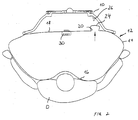
- FIG. 1 shows an airbag protection device for the driver D of a vehicle.
- the protective device is completely in a steering wheel 10 integrates and includes an airbag 12 with an outer wall 14 made of fabric material, which has a front side 16 facing the occupant D and a rear side 18 facing the steering wheel 10.
- the outer wall 14 has at least one outflow opening 20.
- a balloon-like membrane 24 made of stretchable, preferably elastomeric material is attached to the edge 22 of the outflow opening 20 and covers and closes the outflow opening 20 in the state shown in FIG.
- the protective device also includes a device 26 for destroying the membrane 24, which has the shape of a spike-like extension facing the rear side 18 and which is located on the inside of the steering wheel 10, e.g. sits in the area of the transition from a spoke to the hub.
- the device 26 can be an extension of the steering wheel skeleton, for example.
- blowing mouth In the area of the so-called blowing mouth of the gas bag 12, a gas generator 30 projects into the interior thereof.
- the blowing mouth is provided with the reference number 32 in FIG.
- the membrane 24 protrudes into the interior of the outflow opening 20 in the region of the edge 22 and, as indicated on the right-hand side, can also have a section which rests on the inside against the outer wall 14 and is fastened there , The area of the membrane 24 which is attached directly to the outer wall 14 is closed in a ring.
- Figure 1 shows a state of the gas bag 12 when it is almost completely inflated and unfolded.
- the occupant D is not yet immersed in the gas bag 12.
- the membrane 24 is still arranged inward of the outflow opening 20 and seals the interior of the gas bag.
- the membrane 24 is not fastened to the gas bag wall, but instead, for example, in a gas bag module housing on the rear wall thereof in the region of a rear-side outflow opening.
- the rear side 18 of the gas bag is virtually replaced by the housing for the gas bag 12.
Landscapes
- Engineering & Computer Science (AREA)
- Mechanical Engineering (AREA)
- Air Bags (AREA)
Abstract
Description
- Die Erfindung betrifft eine Gassack-Schutzeinrichtung.
- Gassäcke sollen sehr schnell aufgeblasen werden und dann, wenn der Insasse in sie hineintaucht, auch eine gewisse Nachgiebigkeit besitzen. Diese zwei Eigenschaften widersprechen sich eigentlich. Deshalb sind ventilähnliche Ausströmöffnungen an der Gassackwand angedacht, die ab Erreichen eines vorbestimmten Drucks Gas entweichen lassen.
- Die Erfindung schafft eine Gassack-Schutzeinrichtung mit einem Gassack, bei dem die Steuerung des Gassackinnendrucks lastabhängig erfolgt, insoweit, als zunächst nur eine geringe Entlastung des Gassackinnendrucks erfolgt, um anschließend bei zunehmender Eintauchtiefe des Insassen in den Gassack den Innendruck gesteuert anzupassen und schließlich sogar ein Entweichen des Gases ab einem bestimmten Druck zuzulassen.
- Die erfindungsgemäße Gassack-Schutzeinrichtung umfaßt einen Gassack, der eine Außenwand aus einem ersten Material aufweist, wobei die Außenwand wenigstens eine Ausströmöffnung hat. Die Gassack-Schutzeinrichtung umfaßt ferner eine Membran aus einem dehnbaren, zweiten Material, das an der Außenwand befestigt ist und die Ausströmöffnung im nicht vollständig aufgeblasenen Zustand des Gassacks bedeckt. Darüber hinaus ist eine außerhalb des Gassacks vorgesehene Einrichtung zum Zerstören der Membran vorgesehen. Die Einrichtung und der Gassack sind so weit voneinander entfernt angeordnet, daß die Membran erst ab Erreichen eines vorbestimmten Gassackinnendrucks auf die Einrichtung trifft und zerstört wird. Bei der erfindungsgemäßen Gassack-Schutzeinrichtung wird, bevor die Membran zerstört wird und ein großer Ausströmquerschnitt zur Verfügung steht, zuerst der Innendruck geringfügig dadurch abgebaut, daß die Membran sich dehnt und ein größeres Volumen zur Verfügung steht. Dies erlaubt es, die Membran beispielsweise wie einen an der Ausströmöffnung angesetzten elastischen Ballon wirken zu lassen, der ein zusätzliches, variables Volumen zur Verfügung stellt. Der Innendruck kann sich dabei an die Belastung von außen in gewisser Hinsicht anpassen. Erst ab Erreichen eines bestimmten, sehr hohen Drucks trifft die Membran auf die Einrichtung, um zerstört zu werden.
- Eine Ausführungsform der Erfindung sieht vor, daß die Membran sich vor Erreichen der Einrichtung ballonartig nach außen vorwölbt.
- Im gefalteten Zustand des Gassacks kann die Membran aber im Inneren des Gassacks angeordnet sein und sich beim Entfalten durch die Austrittsöffnung nach außen stülpen. Damit wird die im Vergleich zur Außenwand empfindlichere Membran beim Einbau z.B. in ein Modulgehäuse geschützt. Darüber hinaus wird die Membran, solange sie sich nicht durch die Ausströmöffnung nach außen stülpt, nicht nennenswert gedehnt, so daß ein nur durch die Außenwand definiertes Volumen des Gassacks in der anfänglichen Aufblasphase zur Verfügung steht, was den Aufblasvorgang beschleunigt. Erst später, wenn der Gassack sich so weit aufgeblasen hat, daß er eine Rückhaltewirkung ausübt, kann dann die Membran in Funktion treten, indem sie sich nach außen stülpt.
- Das Material der Membran ist so gewählt, daß sie im zerstörten Zustand den wirksamen Ausströmquerschnitt definiert, daß bedeutet, sie wird nicht komplett zerstört, sondern es bleibt beispielsweise noch ein ringartiger Abschnitt im Bereich der Ausströmöffnung stehen, der die Ausströmöffnung zusammenzieht und so den wirksamen Ausströmquerschnitt lastabhängig verändert, vorzugsweise reversibel verändert.
- Dies kann beispielsweise dadurch erzielt werden, daß die Membran im zerstörten Zustand so dehnbar ist, daß sie abhängig vom Innendruck den wirksamen Ausströmquerschnitt vergrößert oder verkleinert.
- Vorzugsweise ist die Einrichtung zum Zerstören der Membran an der Innenseite eines Fahrzeuglenkrads vorgesehen, z.B. indem sie als eine Art Dorn ausgeführt ist.
- Weitere Merkmale und Vorteile der Erfindung ergeben sich aus der nachfolgenden Beschreibung und aus den nachfolgenden Zeichnungen, auf die Bezug genommen wird. In den Zeichnungen zeigen:
- Figur eine Draufsicht auf den Fahrzeuginnenraum im Bereich des Fahrers, die die Gassack-Schutzeinrichtung nach der Erfindung vor dem Eintauchen des Fahrers und im fast vollständig aufgeblasenen Zustand zeigt,
- Figur 2 eine Figur 1 entsprechende Ansicht mit der Gassack-Schutzeinrichtung zu Beginn des Eintauchvorgangs des Insassen,
- Figur 3 eine Figur 1 entsprechende Ansicht mit der Gassack-Schutzeinrichtung bei noch weiter eingetauchtem Insassen, kurz vor der Zerstörung der Membran,
- Figur 4 eine Figur 1 entsprechende Ansicht mit der Gassack-Schutzeinrichtung bei zerstörter Membran und
- Figur 5 eine vergrößerte Schnittansicht des bei der erfindungsgemäßen Gassack-Schutzeinrichtung eingesetzten Gassacks im Bereich der Ausströmöffnung.
- In Figur 1 ist eine Gassack-Schutzeinrichtung für den Fahrer D eines Fahrzeugs dargestellt. Die Schutzeinrichtung ist vollständig in ein Lenkrad 10 integriert und umfaßt einen Gassack 12 mit einer Außenwand 14 aus Gewebematerial, der eine dem Insassen D zugewandte Vorderseite 16 und eine dem Lenkrad 10 zugewandte Rückseite 18 besitzt. Im Bereich der Rückseite 18 hat die Außenwand 14 zumindest eine Ausströmöffnung 20. Am Rand 22 der Ausströmöffnung 20 ist eine ballonartige Membran 24 aus dehnbarem, vorzugsweise elastomeren Material befestigt, die in dem in Figur 1 gezeigten Zustand die Ausströmöffnung 20 bedeckt und schließt.
- Zur Schutzeinrichtung gehört auch eine Einrichtung 26 zum Zerstören der Membran 24, die die Form eines dornartigen, der Rückseite 18 zugewandten Fortsatzes hat und die auf der Innenseite des Lenkrads 10, z.B. im Bereich des Übergangs einer Speiche zur Nabe sitzt. Die Einrichtung 26 kann beispielsweise ein Fortsatz des Lenkradskeletts sein.
- Im Bereich des sogenannten Einblasmundes des Gassacks 12 ragt ein Gasgenerator 30 in dessen Inneres. Der Einblasmund ist in Figur 5 mit dem Bezugszeichen 32 versehen.
- In Figur 5 ist auch zu erkennen, daß die Membran 24 im Bereich des Randes 22 in das Innere der Ausströmöffnung 20 ragt und, wie auf der rechten Seite angedeutet, auch einen Abschnitt haben kann, der innenseitig an der Außenwand 14 anliegt und dort befestigt ist. Der Bereich der Membran 24, der unmittelbar an der Außenwand 14 befestigt ist, ist ringförmig geschlossen.
- Figur 1 zeigt einen Zustand des Gassacks 12, wenn dieser fast vollständig aufgeblasen und entfaltet ist. Der Insasse D ist aber noch nicht in den Gassack 12 eingetaucht. In diesem Zustand ist die Membran 24 noch immer einwärts der Ausströmöffnung 20 angeordnet und dichtet das Innere des Gassacks ab.
- Wenn der Insasse beginnt, in den Gassack einzutauchen (Figur 2) erhöht sich der Gassackinnendruck, und die Membran 24 stülpt sich durch die Ausströmöffnung 20 nach außen. Damit wird dem Gassack ein größeres Volumen gegeben, und der Innendruck kann etwas abnehmen.
- Wenn der Fahrer D tiefer in den Gassack 12 eintaucht, erhöht sich der Gassackinnendruck, und die Membran wölbt sich weiter ballonartig nach außen vor, so daß ein gewisser Druckausgleichsraum zur Verfügung steht. Die Membran 24 gelangt näher zur Einrichtung 26 und wird schließlich (Figur 4) zerstört. Dieser Zustand entspricht einem gewissen maximalen Gassackinnendruck, der vorbestimmt werden kann.
- Im zerstörten Zustand der Membran kann diese den wirksamen Ausströmquerschnitt ggf. weiter beeinflussen, nämlich abhängig vom Innendruck vergrößern oder verkleinern. Dies wäre beispielsweise dann möglich, wenn die Membran 24 im Bereich ihrer Befestigung an der Außenwand 14 unzerstört bleibt und wie ein geschlossener Ring aus elastomerem Material wirkt, der die Ausströmöffnung 20 auch zusammenziehen kann.
- Die zuvor erwähnten Vorteile können auch erreicht werden, wenn die Membran 24 nicht an der Gassackwand befestigt ist, sondern beispielsweise in einem Gassack-Modulgehäuse an dessen Rückwand im Bereich einer gehäuseseitigen, rückseitigen Ausströmöffnung. Bei dieser Ausführungsform wird quasi die Rückseite 18 des Gassacks durch das Aufnahmegehäuse für den Gassack 12 ersetzt.
Claims (6)
- Gassack-Schutzeinrichtung, mit
einem Gassack (12), der eine Außenwand (14) aus einem ersten Material aufweist,
wobei die Außenwand (14) wenigstens eine Ausströmöffnung (20) hat,
einer Membran (24) aus einem dehnbaren zweiten Material, das an der Außenwand (14) befestigt ist und die Ausströmöffnung (20) im nicht vollständig aufgeblasenen Zustand des Gassacks (12) bedeckt,
und mit einer außerhalb des Gassacks (12) vorgesehenen Einrichtung (26) zum Zerstören der Membran (24),
wobei der Gassack (12) und die Einrichtung (26) soweit voneinander entfernt angeordnet sind, daß die Membran (24) erst ab Erreichen eines vorbestimmten Gassackinnendrucks auf die Einrichtung (26) trifft. - Gassack-Schutzeinrichtung nach Anspruch 1, dadurch gekennzeichnet, daß die Membran (24) sich vor Erreichen der Einrichtung (26) ballonartig nach außen vorwölbt.
- Gassack-Schutzeinrichtung nach Anspruch 1 oder 2, dadurch gekennzeichnet, daß die Membran (24) im gefaltetem Zustand des Gassacks (12) im Inneren des Gassacks (12) angeordnet ist und sich beim Aufblasen durch die Austrittsöffnung (20) nach außen stülpt.
- Gassack-Schutzeinrichtung nach einem der vorhergehenden Ansprüche, dadurch gekennzeichnet, daß das Material der Membran (24) so ausgebildet ist, daß sie im zerstörten Zustand den wirksamen Ausströmquerschnitt definiert.
- Gassack-Schutzeinrichtung nach Anspruch 4, dadurch gekennzeichnet, daß die Membran (24) im zerstörten Zustand so dehnbar ist, daß sie abhängig vom Innendruck den wirksamen Ausströmquerschnitt vergrößert oder verkleinert.
- Gassack-Schutzeinrichtung nach einem der vorhergehenden Ansprüche, dadurch gekennzeichnet, daß die Einrichtung (26) zum Zerstören der Membran (24) an der Innenseite des Lenkrads (10) vorgesehen ist.
Applications Claiming Priority (2)
| Application Number | Priority Date | Filing Date | Title |
|---|---|---|---|
| DE20212337U | 2002-08-09 | ||
| DE20212337U DE20212337U1 (de) | 2002-08-09 | 2002-08-09 | Gassack-Schutzeinrichtung |
Publications (2)
| Publication Number | Publication Date |
|---|---|
| EP1413487A1 true EP1413487A1 (de) | 2004-04-28 |
| EP1413487B1 EP1413487B1 (de) | 2006-03-01 |
Family
ID=7973998
Family Applications (1)
| Application Number | Title | Priority Date | Filing Date |
|---|---|---|---|
| EP03015509A Expired - Lifetime EP1413487B1 (de) | 2002-08-09 | 2003-07-09 | Gassack-Schutzeinrichtung |
Country Status (4)
| Country | Link |
|---|---|
| US (1) | US7172213B2 (de) |
| EP (1) | EP1413487B1 (de) |
| DE (2) | DE20212337U1 (de) |
| ES (1) | ES2259121T3 (de) |
Cited By (1)
| Publication number | Priority date | Publication date | Assignee | Title |
|---|---|---|---|---|
| EP1876071A3 (de) * | 2006-07-08 | 2009-01-21 | Dr. Ing. h.c. F. Porsche Aktiengesellschaft | Aufblasbare Fahrzeuginsassenschutzeinrichtung |
Families Citing this family (8)
| Publication number | Priority date | Publication date | Assignee | Title |
|---|---|---|---|---|
| JP4890391B2 (ja) * | 2007-08-24 | 2012-03-07 | 本田技研工業株式会社 | エアバッグ装置 |
| US8523220B1 (en) | 2012-03-19 | 2013-09-03 | Amsafe, Inc. | Structure mounted airbag assemblies and associated systems and methods |
| DE102013113434B4 (de) * | 2013-12-04 | 2017-03-02 | Autoliv Development Ab | Gassackmodul mit einer eine Aufspringfalte aufweisenden Venteinrichtung |
| US9944245B2 (en) | 2015-03-28 | 2018-04-17 | Amsafe, Inc. | Extending pass-through airbag occupant restraint systems, and associated systems and methods |
| SG11201708221UA (en) * | 2015-04-11 | 2017-11-29 | Amsafe Inc | Active airbag vent system |
| US10604259B2 (en) | 2016-01-20 | 2020-03-31 | Amsafe, Inc. | Occupant restraint systems having extending restraints, and associated systems and methods |
| DE102021122898A1 (de) * | 2021-09-03 | 2023-03-09 | Dalphi Metal Espana, S.A. | Lenkrad mit einem gassack |
| US12496995B2 (en) * | 2024-04-11 | 2025-12-16 | Ford Global Technologies, Llc | Vehicle airbag with elastic vent assembly |
Citations (6)
| Publication number | Priority date | Publication date | Assignee | Title |
|---|---|---|---|---|
| JPH06286570A (ja) * | 1993-03-30 | 1994-10-11 | Hino Motors Ltd | 車両用のエアバッグシステム |
| GB2306409A (en) * | 1995-10-23 | 1997-05-07 | Autoliv Dev | Airbag vent valves opened by a command signal |
| EP0917995A1 (de) * | 1997-11-19 | 1999-05-26 | TRW Automotive Safety Systems GmbH | Regelbarer Auslassquerschnitt an einem Gassack |
| EP1022198A1 (de) * | 1999-01-20 | 2000-07-26 | Aerazur | Luftsack mit einer die Abströmöffnung verschliessenden Membran |
| US6322099B1 (en) * | 2000-06-30 | 2001-11-27 | Timothy E. Keeble | Device for deflating and restraining inadvertently deployed vehicle airbag |
| WO2002014115A1 (es) * | 2000-08-03 | 2002-02-21 | Dalphi Metal España, S.A. | Airbag con parche de obturacion del orificio de descarga de gas de espesor variable |
Family Cites Families (8)
| Publication number | Priority date | Publication date | Assignee | Title |
|---|---|---|---|---|
| US3758133A (en) * | 1970-06-04 | 1973-09-11 | Honda Motor Co Ltd | Shock absorbing air bag apparatus in a motor car |
| US5725244A (en) * | 1996-07-09 | 1998-03-10 | Breed Automotive Technology, Inc. | Airbag venting mechanism |
| DE29720461U1 (de) * | 1997-11-19 | 1998-02-26 | Trw Automotive Safety Sys Gmbh | Gassack mit regelbarem Auslaßquerschnitt |
| DE10111566B4 (de) * | 2001-03-10 | 2005-11-17 | Daimlerchrysler Ag | Sicherheitsvorrichtung für ein Kraftfahrzeug |
| US6648371B2 (en) * | 2001-07-12 | 2003-11-18 | Delphi Technologies, Inc. | Variable venting air bag assembly |
| JP4759867B2 (ja) * | 2001-07-25 | 2011-08-31 | タカタ株式会社 | エアバッグ装置 |
| US6517108B1 (en) * | 2002-01-02 | 2003-02-11 | Ford Global Technologies, Inc. | Pyrotechnic air bag stitch vent |
| GB2394919B (en) * | 2002-11-06 | 2006-01-25 | Autoliv Dev | Improvements in or relating to an air-bag arrangement |
-
2002
- 2002-08-09 DE DE20212337U patent/DE20212337U1/de not_active Expired - Lifetime
-
2003
- 2003-07-09 DE DE50302501T patent/DE50302501D1/de not_active Expired - Fee Related
- 2003-07-09 ES ES03015509T patent/ES2259121T3/es not_active Expired - Lifetime
- 2003-07-09 EP EP03015509A patent/EP1413487B1/de not_active Expired - Lifetime
- 2003-07-29 US US10/630,027 patent/US7172213B2/en not_active Expired - Fee Related
Patent Citations (6)
| Publication number | Priority date | Publication date | Assignee | Title |
|---|---|---|---|---|
| JPH06286570A (ja) * | 1993-03-30 | 1994-10-11 | Hino Motors Ltd | 車両用のエアバッグシステム |
| GB2306409A (en) * | 1995-10-23 | 1997-05-07 | Autoliv Dev | Airbag vent valves opened by a command signal |
| EP0917995A1 (de) * | 1997-11-19 | 1999-05-26 | TRW Automotive Safety Systems GmbH | Regelbarer Auslassquerschnitt an einem Gassack |
| EP1022198A1 (de) * | 1999-01-20 | 2000-07-26 | Aerazur | Luftsack mit einer die Abströmöffnung verschliessenden Membran |
| US6322099B1 (en) * | 2000-06-30 | 2001-11-27 | Timothy E. Keeble | Device for deflating and restraining inadvertently deployed vehicle airbag |
| WO2002014115A1 (es) * | 2000-08-03 | 2002-02-21 | Dalphi Metal España, S.A. | Airbag con parche de obturacion del orificio de descarga de gas de espesor variable |
Non-Patent Citations (1)
| Title |
|---|
| PATENT ABSTRACTS OF JAPAN vol. 1995, no. 01 28 February 1995 (1995-02-28) * |
Cited By (1)
| Publication number | Priority date | Publication date | Assignee | Title |
|---|---|---|---|---|
| EP1876071A3 (de) * | 2006-07-08 | 2009-01-21 | Dr. Ing. h.c. F. Porsche Aktiengesellschaft | Aufblasbare Fahrzeuginsassenschutzeinrichtung |
Also Published As
| Publication number | Publication date |
|---|---|
| DE50302501D1 (de) | 2006-04-27 |
| US7172213B2 (en) | 2007-02-06 |
| ES2259121T3 (es) | 2006-09-16 |
| EP1413487B1 (de) | 2006-03-01 |
| DE20212337U1 (de) | 2002-10-02 |
| US20040026911A1 (en) | 2004-02-12 |
Similar Documents
| Publication | Publication Date | Title |
|---|---|---|
| EP1778525B1 (de) | Gassack für ein airbagmodul eines kraftfahrzeuges | |
| DE69004354T2 (de) | Gassack-Aufprallschutzvorrichtung. | |
| DE19522765A1 (de) | Airbagmodul | |
| DE4028715A1 (de) | Gaskissen-aufprallschutzvorrichtung | |
| EP1008494A2 (de) | Gassack-Seitenaufprall-Schutzeinrichtung | |
| DE69708783T2 (de) | Hybride Aufblasvorrichtung mit herausspringenden Diffuser | |
| EP1413487B1 (de) | Gassack-Schutzeinrichtung | |
| EP3658421B1 (de) | Überzündschutzvorrichtung, zweite zündstufe, gasgenerator sowie gassackmodul | |
| DE10361887A1 (de) | Airbageinrichtung für ein Kraftfahrzeug | |
| EP1048533A1 (de) | Schutzeinrichtung mit Gassack für Kraftfahrzeug-Insassen | |
| DE2024813B2 (de) | Aufprallschutzvorrichtung für die Insassen eines Kraftwagens | |
| DE19923483A1 (de) | Airbag für ein Kraftfahrzeug | |
| DE2359952A1 (de) | Sicherheitseinrichtung fuer kraftfahrzeuginsassen | |
| DE69608508T2 (de) | Druckregelvorrichtung für ein Kraftfahrzeug-Airbagmodul | |
| DE102005051982A1 (de) | Aufblasvorrichtung mit Schockwellen fokussierender Struktur | |
| EP1710137B1 (de) | Fahrzeuginsassen-Rückhaltevorrichtung | |
| DE19548571C1 (de) | Vorrichtung zum schnellen Aufblasen eines Luftkissens | |
| DE10150772C1 (de) | Ein Airbagmodul aufweisendes Lenkrad mit sich einstellendem Öffnungswinkel seiner Abdeckklappe | |
| DE60110125T2 (de) | Airbag mit Austrittsöffnungen, die zur differenzierten Steuerung der Entlüf- tungsfläche und des Berstdrucks im Verschlussaufsatz ausgelegt sind | |
| DE102012220983B4 (de) | Gassackanordnung für ein Fahrzeuginsassen-Rückhaltesystem | |
| EP1854679B1 (de) | Lenkvorrichtung mit Gassack für ein Kraftfahrzeug | |
| DE4011492A1 (de) | Gaskissen-aufprallschutzvorrichtung | |
| DE102017211281B4 (de) | Gasgenerator mit einer Berstscheibe aus einem Elastomer | |
| DE102004042209A1 (de) | Airbageinrichtung | |
| EP1249373B1 (de) | Lenksäule für Kraftfahrzeuge |
Legal Events
| Date | Code | Title | Description |
|---|---|---|---|
| PUAI | Public reference made under article 153(3) epc to a published international application that has entered the european phase |
Free format text: ORIGINAL CODE: 0009012 |
|
| AK | Designated contracting states |
Kind code of ref document: A1 Designated state(s): AT BE BG CH CY CZ DE DK EE ES FI FR GB GR HU IE IT LI LU MC NL PT RO SE SI SK TR |
|
| AX | Request for extension of the european patent |
Extension state: AL LT LV MK |
|
| 17P | Request for examination filed |
Effective date: 20041005 |
|
| AKX | Designation fees paid |
Designated state(s): DE ES FR GB IT |
|
| GRAP | Despatch of communication of intention to grant a patent |
Free format text: ORIGINAL CODE: EPIDOSNIGR1 |
|
| GRAS | Grant fee paid |
Free format text: ORIGINAL CODE: EPIDOSNIGR3 |
|
| GRAA | (expected) grant |
Free format text: ORIGINAL CODE: 0009210 |
|
| AK | Designated contracting states |
Kind code of ref document: B1 Designated state(s): DE ES FR GB IT |
|
| PG25 | Lapsed in a contracting state [announced via postgrant information from national office to epo] |
Ref country code: GB Free format text: LAPSE BECAUSE OF FAILURE TO SUBMIT A TRANSLATION OF THE DESCRIPTION OR TO PAY THE FEE WITHIN THE PRESCRIBED TIME-LIMIT Effective date: 20060301 |
|
| REG | Reference to a national code |
Ref country code: GB Ref legal event code: FG4D Free format text: NOT ENGLISH |
|
| REF | Corresponds to: |
Ref document number: 50302501 Country of ref document: DE Date of ref document: 20060427 Kind code of ref document: P |
|
| REG | Reference to a national code |
Ref country code: ES Ref legal event code: FG2A Ref document number: 2259121 Country of ref document: ES Kind code of ref document: T3 |
|
| GBV | Gb: ep patent (uk) treated as always having been void in accordance with gb section 77(7)/1977 [no translation filed] |
Effective date: 20060301 |
|
| ET | Fr: translation filed | ||
| PLBE | No opposition filed within time limit |
Free format text: ORIGINAL CODE: 0009261 |
|
| STAA | Information on the status of an ep patent application or granted ep patent |
Free format text: STATUS: NO OPPOSITION FILED WITHIN TIME LIMIT |
|
| 26N | No opposition filed |
Effective date: 20061204 |
|
| PGFP | Annual fee paid to national office [announced via postgrant information from national office to epo] |
Ref country code: DE Payment date: 20080731 Year of fee payment: 6 Ref country code: ES Payment date: 20080708 Year of fee payment: 6 |
|
| PGFP | Annual fee paid to national office [announced via postgrant information from national office to epo] |
Ref country code: FR Payment date: 20080707 Year of fee payment: 6 |
|
| REG | Reference to a national code |
Ref country code: FR Ref legal event code: ST Effective date: 20100331 |
|
| PG25 | Lapsed in a contracting state [announced via postgrant information from national office to epo] |
Ref country code: FR Free format text: LAPSE BECAUSE OF NON-PAYMENT OF DUE FEES Effective date: 20090731 |
|
| PGFP | Annual fee paid to national office [announced via postgrant information from national office to epo] |
Ref country code: IT Payment date: 20090722 Year of fee payment: 7 |
|
| PG25 | Lapsed in a contracting state [announced via postgrant information from national office to epo] |
Ref country code: DE Free format text: LAPSE BECAUSE OF NON-PAYMENT OF DUE FEES Effective date: 20100202 |
|
| REG | Reference to a national code |
Ref country code: ES Ref legal event code: FD2A Effective date: 20090710 |
|
| PG25 | Lapsed in a contracting state [announced via postgrant information from national office to epo] |
Ref country code: ES Free format text: LAPSE BECAUSE OF NON-PAYMENT OF DUE FEES Effective date: 20090710 |
|
| PG25 | Lapsed in a contracting state [announced via postgrant information from national office to epo] |
Ref country code: IT Free format text: LAPSE BECAUSE OF NON-PAYMENT OF DUE FEES Effective date: 20100709 |