EP1413483A1 - Door mirror assembly for a vehicle - Google Patents
Door mirror assembly for a vehicle Download PDFInfo
- Publication number
- EP1413483A1 EP1413483A1 EP20030256544 EP03256544A EP1413483A1 EP 1413483 A1 EP1413483 A1 EP 1413483A1 EP 20030256544 EP20030256544 EP 20030256544 EP 03256544 A EP03256544 A EP 03256544A EP 1413483 A1 EP1413483 A1 EP 1413483A1
- Authority
- EP
- European Patent Office
- Prior art keywords
- housing
- engagement
- attachment
- frame
- shell
- Prior art date
- Legal status (The legal status is an assumption and is not a legal conclusion. Google has not performed a legal analysis and makes no representation as to the accuracy of the status listed.)
- Granted
Links
- 238000006073 displacement reaction Methods 0.000 claims abstract description 23
- 210000000078 claw Anatomy 0.000 claims description 29
- 229920003002 synthetic resin Polymers 0.000 description 4
- 239000000057 synthetic resin Substances 0.000 description 4
- 230000002596 correlated effect Effects 0.000 description 3
- 238000004519 manufacturing process Methods 0.000 description 3
- 238000000034 method Methods 0.000 description 3
- 230000001276 controlling effect Effects 0.000 description 2
- 238000003780 insertion Methods 0.000 description 2
- 230000037431 insertion Effects 0.000 description 2
- 230000014759 maintenance of location Effects 0.000 description 2
- 238000000465 moulding Methods 0.000 description 2
- 239000000853 adhesive Substances 0.000 description 1
- 230000001070 adhesive effect Effects 0.000 description 1
- 230000002411 adverse Effects 0.000 description 1
- 238000000429 assembly Methods 0.000 description 1
- 239000011449 brick Substances 0.000 description 1
- 244000145845 chattering Species 0.000 description 1
- 238000010276 construction Methods 0.000 description 1
- 230000003247 decreasing effect Effects 0.000 description 1
- 230000005489 elastic deformation Effects 0.000 description 1
- 238000003466 welding Methods 0.000 description 1
Images



Classifications
-
- B—PERFORMING OPERATIONS; TRANSPORTING
- B60—VEHICLES IN GENERAL
- B60R—VEHICLES, VEHICLE FITTINGS, OR VEHICLE PARTS, NOT OTHERWISE PROVIDED FOR
- B60R1/00—Optical viewing arrangements; Real-time viewing arrangements for drivers or passengers using optical image capturing systems, e.g. cameras or video systems specially adapted for use in or on vehicles
- B60R1/02—Rear-view mirror arrangements
- B60R1/06—Rear-view mirror arrangements mounted on vehicle exterior
Definitions
- the present invention relates to a door mirror assembly for a vehicle characterized by the structure of the attachment between a door mirror housing and a frame.
- a door mirror assembly for a vehicle has conventionally been constructed of various elements and sub-assemblies, including a mirror, a control sub-assembly for controlling the angle of the mirror and a drive sub-assembly for positioning the door mirror assembly in a retracted or an operative position, all of which are installed in a shell called a door mirror housing.
- the door mirror housing which is made of a synthetic resin, is susceptible to mechanical deformation such as torsion, it has been common to incorporate an element such as a frame into the door mirror housing. In this case, the door mirror housing and frame are commonly fixed with fasteners such as screws at three or more locations.
- Japanese Patent No. 3301571 Japanese Patent No. 3301571
- Japanese Published Patent Application 10-100794 disclose such techniques.
- Japanese Published Patent Application 2001-294087 discloses clips made of a synthetic resin and Japanese Published Patent Application 08-244532 discloses the application of ultrasonic welding.
- An object of the present invention is to provide a door mirror assembly for a vehicle, which preferably not only achieves a reduction in the number of parts for fixing a door mirror housing and a frame but also ensures adequate attachment strength there between as well as providing easy assembly and having low cost.
- a door mirror assembly for a vehicle, which includes a housing, and a frame supporting the housing internally.
- the housing has a shell with a front aperture, two attachment ports formed on the inner surface of shell and an engagement port formed integrally with the shell.
- the frame has a main body to be enclosed by the shell, two attachment elements formed on the outer surface of main body and an engagement element formed integrally with the main body.
- the door mirror assembly further includes two attachment sections formed by attaching the two attachment ports and two attachment elements using fasteners and an engagement section formed by engaging the engagement port with the engagement element.
- the engagement section is adapted to be on the circumference of a circle, and the center of that circle lies on an axis defined by the two attachment sections, so that the rotational displacement of housing relative to the frame can be restricted. Put another way, the engagement section is radially spaced from the line connecting the two attachment sections.
- the door mirror assembly described above employs attachment between the housing and frame with the two attachment sections and the engagement section, which is on the circumference of circle characterized spatially as described above.
- the optimal positioning of the engagement section allows the number of attachment sections, which require fasteners to be reduced to two.
- the engagement section is formed simply by engaging the engagement port, which is formed integrally with the shell of housing, and the engagement element, which is formed integrally with the main body of frame. Therefore, the door mirror assembly can allow both easy assembly and a reduction in the number of parts as well as the number of man-hours associated with its assembly.
- the attachment strength of the engagement section is lower than that of the attachment sections, it maybe possible to obtain adequate attachment strength for fixing the housing and frame to each other using the two attachment sections due to the optimum positioning of the engagement section.
- the housing When a housing and a frame are fixed at only two locations (the attachment sections), the housing, which is not a rigid body, generally experiences displacement relative to the frame about an axis defined by the two attachment sections.
- Another aspect of the present invention provides a door mirror assembly, which may be as described in the previous aspect and which has at least two engagement sections wherein the engagement sections restrict the rotational displacement of housing in opposite directions to each other.
- the door mirror assembly described above employs two attachment sections and two or more engagement sections for fixing the housing and the frame, the engagement sections restrict the rotational displacement of housing in opposite directions to each other so that the housing can not be unsteady relative to the frame.
- Addition of an attachment section which requires an increase in the number of parts, will generally result in an increase in the product cost.
- the product cost will not generally increase if the number of engagement sections is increased. The reason for this is that an engagement port and an engagement element can be formed integrally with the molding of the housing and the frame, respectively.
- Still another aspect of the present invention provides a door mirror assembly, which may be as described in either of the previous aspects, in which an engagement port includes a hole drilled into a shell, and an engagement element includes a column projecting from a main body and the column has a claw at an end thereof.
- the column is adapted to reach beyond the outer surface of the shell through the hole while the column is in contact with a side wall of the hole, and the claw is also adapted to be in contact with the periphery of the hole.
- the door mirror assembly described above which has a simple structure for engagement such that the column formed on the frame is engaged with the hole drilled into the shell, may enable a reduction in the production cost.
- Yet another aspect of the present invention provides a door mirror assembly, which may be as described in any one of the previous aspects and which has a column having a contact surface which is in contact with the inner surface of a shell.
- the door mirror assembly described above in which the shell of a housing is interposed between a claw and the contact surface, can provide a higher attachment strength.
- a further aspect of the present invention provides a door mirror assembly, which may be as described in any one of the previous aspects and which has a claw adapted to be positioned so that a direction of the width of the claw is substantially parallel with an axis defined by two attachment sections.
- the door mirror assembly described above can apply the force to engagement sections evenly, which restricts the rotational displacement and deformation of a housing in a circumferential direction.
- a door mirror assembly for a vehicle includes a door mirror housing (hereinafter referred to as a housing H) and a frame F which supports the housing H internally.
- the door mirror assembly is mounted on a mirror base 101 which is provided on the side of a vehicle 100, as shown in FIG.2A.
- the door mirror assembly also includes a mirror (not shown) which is installed in the front aperture of housing H, and accommodates a control sub-assembly (not shown) for controlling the angle of mirror within the housing H.
- the housing H includes a shell 10 made of a synthetic resin, upper and lower attachment ports 11 and 12 which are formed on the inner surface of shell 10 and first and second engagement ports 13 and 14 which are formed integrally with the shell 10.
- the positions of the upper and lower attachment ports 11, 12 and the first and second engagement ports 13, 14 are correlated with those of upper and lower attachment elements 21, 22 and first and second engagement elements 23, 24, respectively.
- the upper attachment port 11 has a bearing surface 11a, which is formed on the upper middle part of the inner surface of shell 10 and a screw hole 11b drilled into the bearing surface 11a.
- FIG.3A which depicts a cross sectional view taken along line IIIA - IIIA in FIG.2A, an L-shaped portion recessed inwardly into the shell 10 forms the upper attachment port 11.
- the lower portion of side surface 11c of upper attachment port 11 is configured to be part-circular, as shown in FIG.1.
- a lower attachment port 12 which is formed at the bottom of shell 10, has a bearing surface 12a and a screw hole 12b drilled into the center of the bearing surface 12a.
- the first engagement port 13 has a hole 13a, which is rectangular and integrally formed with the shell 10.
- the position of first engagement port 13 is correlated with that of first engagement element 23, and the hole 13a is adapted such that its size is appropriate for insertion of a claw 23b as shown in FIG.5.
- the second engagement port 14 has a hole 14a, which has a T-shaped section and is formed integrally with the shell 10.
- the position of second engagement port 14 is correlated with that of second engagement element 24, and the hole 14a is arranged so that the width of its upper portion is larger than that of the lower portion.
- the width of the upper portion of the hole 14a is adapted such that its size is appropriate for insertion of a claw 24b as shown in FIG.5.
- the width of the lower portion is adapted to be same as the thickness of the column 24a shown in FIG.5.
- the frame F includes a main body 20, which is made of a synthetic resin and nearly L-shaped as viewed from the side thereof.
- the upper and lower attachment elements 21, 22 are formed on the outer surface of main body 20 and the first and second engagement elements 23, 24 are formed integrally with the main body 20.
- a drive assembly M is also mounted on the main body 20 for positioning the door mirror assembly in a retracted or operative position.
- a symbol S1 represents a base of shaft for transmitting drive power generated by the drive assembly M.
- the upper attachment element 21, which is formed on the upper end of main body 20, has a mounting surface 21a which comes in contact with the bearing surface 11a of housing H shown in FIG.1 and a screw hole 21b drilled into the mounting surface 21a.
- the upper attachment element 21 is located at a thinned portion of the upper end of main body 20.
- a contact surface 21c of upper attachment element 21 is adapted to be part-circular, the axis of the circle being substantially perpendicular to the axis P defined by the screw holes 21b and 22b, and comes into contact with the side surface 11c of upper attachment port 11 shown in FIG.1.
- the lower attachment element 22 which is formed at the bottom of main body 20, has a mounting surface 22a which contacts the bearing surface 12a of housing H and a screw hole 22b drilled into the mounting surface 22a.
- the first engagement element 23 includes a column 23a, which is plate like and formed on the outer surface of main body 20, facing the shell 10.
- the column 23a extends beyond the outside surface of shell 10 through the hole 13a while it is in contact with the side wall of hole 13a.
- the column 23a has a claw 23b at the end thereof.
- a surface of the claw 23b facing the main body 20 comes in contact with a periphery 13b of hole 13a flush with the outer surface of shell 10.
- the claw 23b is positioned so that the direction of its width is substantially parallel with the axis P defined by the screw holes 21b and 22b.
- the second engagement element 24 has a column 24a like a brick, and is formed on the outer surface of main body 20 facing the shell 10.
- the column 24a extends beyond the outer surface of shell 10 through the hole 14a while it is in contact with the side wall of hole 14a.
- the column 24a also has a claw 24b at the end thereof and a contact surface 24c parallel to the claw 24b in the middle thereof.
- the distance between the inner (lower) surface of claw 24b and contact surface 24c is adapted to be equal to the thickness of shell 10 (see FIG.5).
- a surface of the claw 24b facing the main body 20 comes into contact with a periphery 14b of hole 14a flush with the outer surface of shell 10.
- the contact surface 24c comes into contact with a periphery 14c of hole 14a flush with the inner surface of shell 10.
- the claw 24b is positioned so that the direction of its width is substantially parallel with the axis P.
- the upper and lower attachment elements 21, 22 and the first and second engagement elements 23, 24 are provided peripherally on the main body 20, as shown in FIGs.4A and 4B.
- This type of arrangement which enables positioning of the elements in an evenly dispersed manner over the main body 20, allows stable retention of the housing H.
- the claw 23b of column 23a and the claw 24b of column 24a are positioned on the circumferences of imaginary circles R1 and R2 respectively, the centers of which lie on the axis P defined by the upper and lower attachment elements 21 and 22.
- a method for fixing a housing H and a frame F is described in detail below.
- the frame F is mounted at a predetermined position inside the housing H. More specifically, while the base S1 of shaft attached to the frame F is positioned above a shaft hole S2 drilled into the bottom of the shell 10, the second engagement element 24 of frame F is inserted into the upper portion of larger width of the hole 14a so that the claw 24b shown in FIG.5 reaches the outside of shell 10.
- the frame F is slid diagonally downward, in the Y2 direction shown in FIG.2A, so that the column 24a is inserted into the smaller width (lower) portion of hole 14a until it rests on the bottom thereof.
- This engaged section is hereinafter referred to as the second engagement section 4.
- the column 24a comes into contact with both side walls of the hole 14a, and the inner side surface of claw 24b facing the main body 20 comes into contact with the periphery 14b of the hole 14a.
- the contact surface 24c comes into contact with the other periphery 14c of the hole 14a.
- the shell 10 of housing H is interposed between the claw 24b and contact surface 24c. Since the claw 24b of column 24a is positioned on the circumference of an imaginary circle R2, the center of which lies on an axis P defined by screw holes 21b and 22b as shown in FIG.4A, the second engagement section 4 is accordingly positioned on the same circumference.
- the hole 13a of housing H and the column 23a of frame F are aligned and the frame F is urged toward the housing H.
- the column 23a deforms elastically in order to enter the hole 13a.
- the claw 23b reaches the outside of shell 10
- the column 23a recovers from this elastic deformation and the column 23a and hole 13a are thereby engaged.
- This engaged section is hereinafter referred to as the first engagement section 3.
- the column 23a comes in contact with a side wall of the hole 13a, and the inner side surface of the claw 23b facing the main body 20 comes in contact with the periphery 13b of hole 13a.
- the first engagement section 3 is accordingly positioned on the same circumference.
- the first engagement section 3 restricts the rotational displacement of housing H relative to the frame F in the direction identified by the arrow R12 (R22).
- the second engagement section 4 restricts the rotational displacement in the reverse direction identified by the arrow R21 (R11).
- the bearing surface 11a of the upper attachment port 11 comes into contact with the mounting surface 21a of the upper attachment element 21 and the screw hole 11b of the upper attachment port 11 and the screw hole 21b of upper attachment element 21 are aligned.
- the bearing surface 12a of the lower attachment port 12 comes into contact with the mounting surface 22a of the lower attachment element 22 and the screw hole 12b of the lower attachment port 12 and a screw hole 22b of the lower attachment element 22 are aligned.
- a fastener 31 such as a screw
- This attached section is hereinafter referred to as an upper attachment section 1.
- a fasteners 32 is screwed into the screw hole 12b from the outside of housing H so that the lower attachment port 12 and the lower attachment element 22 are attached.
- This attached section is hereinafter referred to as a lower attachment section 2.
- the housing H and frame F are attached to each other by the upper and lower attachment sections 1, 2 as shown in FIG.2A, and the first and second engagement sections 3, 4, which are positioned on the circumferences of circles that have centers lying on the axis P are engaged. Attachment of the housing H and frame F at only two locations this way can allow a reduction in the number of parts and man-hour expenditure associated with the assembling of a door mirror assembly.
- the housing H and frame F are attached at only two locations, adequate attachment strength can be obtained as a result of an appropriate positioning of the first and second engagement sections 3 and 4. Since the first and second engagement sections 3 and 4 are positioned on the circumferences of circles, as shown in FIG.6, the centers of which lie on the axis P defined by a line drawn between the upper and lower attachment sections 1 and 2, the rotational displacement (i.e. torsional displacement about the axis P) of housing H relative to the frame F is restricted, which as a result improves the attachment strength.
- the housing H which intrinsically tends to rotate around the axis P relative to the frame F, will not rattle under high attachment strength as a result of the restriction provided by the first and second engagement sections 3 and 4.
- the first and second engagement sections 3 and 4 which are positioned offset from the axis P, can restrict rotational movements in the directions identified by the arrows R12 and R21, respectively.
- the first engagement section 3 is assembled by inserting the column 23a, integrally formed with the main body 20 of frame F, into the hole 13a integrally formed with the shell 10 of housing H.
- the second engagement section 4 is assembled in the similar manner to that of the first engagement section 3.
- the present embodiment which uses a simple structure for the holes 13a and 14a drilled into the housing H, as well as for the columns 23a and 24a integrally formed with the frame F, can provide a reduction in production cost.
- housing H and frame F of the present embodiment may be modified according to the vehicle to which the door mirror assembly is mounted.
- the construction of each engagement port of housing H and each engagement element of frame F is also not limited to those described in the above embodiment.
- a claw may be formed on the housing H and a hole drilled into the frame F.
- this can be reduced to one, or increased as required.
Landscapes
- Engineering & Computer Science (AREA)
- Multimedia (AREA)
- Mechanical Engineering (AREA)
- Rear-View Mirror Devices That Are Mounted On The Exterior Of The Vehicle (AREA)
Abstract
Description
- The present invention relates to a door mirror assembly for a vehicle characterized by the structure of the attachment between a door mirror housing and a frame.
- A door mirror assembly for a vehicle has conventionally been constructed of various elements and sub-assemblies, including a mirror, a control sub-assembly for controlling the angle of the mirror and a drive sub-assembly for positioning the door mirror assembly in a retracted or an operative position, all of which are installed in a shell called a door mirror housing. Since the door mirror housing, which is made of a synthetic resin, is susceptible to mechanical deformation such as torsion, it has been common to incorporate an element such as a frame into the door mirror housing. In this case, the door mirror housing and frame are commonly fixed with fasteners such as screws at three or more locations. Japanese Patent No. 3301571 (Japanese Published Patent application 07-223489) and Japanese Published Patent Application 10-100794 disclose such techniques.
- In this connection, other two documents report techniques, which do not employ screws, for fixing a door mirror housing and a frame. Japanese Published Patent Application 2001-294087 discloses clips made of a synthetic resin and Japanese Published Patent Application 08-244532 discloses the application of ultrasonic welding.
- It is understood that a reduction in the number of parts and man-hour expenditure will contribute to a reduction in the production cost of a door mirror assembly for a vehicle. It is therefore important to improve working efficiency as a result of a reduction in the number of fasteners such as screws in fixing a door mirror housing and a frame. However, if the number of fasteners such as screws and clips is simply decreased without further consideration for a conventional door mirror assembly, the resultant attachment strength will be inadequate. This may lead to problems in that vibration or "chattering" of a mirror during vehicular travel adversely affects the visibility of a driver or that resultant noise spoils the comfortableness in the vehicle cabin.
- An object of the present invention is to provide a door mirror assembly for a vehicle, which preferably not only achieves a reduction in the number of parts for fixing a door mirror housing and a frame but also ensures adequate attachment strength there between as well as providing easy assembly and having low cost.
- One aspect of the present invention provides a door mirror assembly for a vehicle, which includes a housing, and a frame supporting the housing internally. The housing has a shell with a front aperture, two attachment ports formed on the inner surface of shell and an engagement port formed integrally with the shell. On the other hand, the frame has a main body to be enclosed by the shell, two attachment elements formed on the outer surface of main body and an engagement element formed integrally with the main body.
- The door mirror assembly further includes two attachment sections formed by attaching the two attachment ports and two attachment elements using fasteners and an engagement section formed by engaging the engagement port with the engagement element. The engagement section is adapted to be on the circumference of a circle, and the center of that circle lies on an axis defined by the two attachment sections, so that the rotational displacement of housing relative to the frame can be restricted. Put another way, the engagement section is radially spaced from the line connecting the two attachment sections.
- The door mirror assembly described above employs attachment between the housing and frame with the two attachment sections and the engagement section, which is on the circumference of circle characterized spatially as described above. Preferably, the optimal positioning of the engagement section allows the number of attachment sections, which require fasteners to be reduced to two. The engagement section is formed simply by engaging the engagement port, which is formed integrally with the shell of housing, and the engagement element, which is formed integrally with the main body of frame. Therefore, the door mirror assembly can allow both easy assembly and a reduction in the number of parts as well as the number of man-hours associated with its assembly. In this connection, although the attachment strength of the engagement section is lower than that of the attachment sections, it maybe possible to obtain adequate attachment strength for fixing the housing and frame to each other using the two attachment sections due to the optimum positioning of the engagement section.
- When a housing and a frame are fixed at only two locations (the attachment sections), the housing, which is not a rigid body, generally experiences displacement relative to the frame about an axis defined by the two attachment sections. Addition of an engagement section adapted to be on the circumference of a circle, the center of which lies on the above axis, restricts the rotational displacement (torsional displacement about the axis), thereby increasing the attachment strength. It is noted that the addition of an engagement section does not generally result in an increase in the product cost since the engagement port and the engagement element are formed integrally with the molding of the housing and the frame, respectively.
- Another aspect of the present invention provides a door mirror assembly, which may be as described in the previous aspect and which has at least two engagement sections wherein the engagement sections restrict the rotational displacement of housing in opposite directions to each other.
- Since the door mirror assembly described above employs two attachment sections and two or more engagement sections for fixing the housing and the frame, the engagement sections restrict the rotational displacement of housing in opposite directions to each other so that the housing can not be unsteady relative to the frame. Addition of an attachment section, which requires an increase in the number of parts, will generally result in an increase in the product cost. On the other hand, the product cost will not generally increase if the number of engagement sections is increased. The reason for this is that an engagement port and an engagement element can be formed integrally with the molding of the housing and the frame, respectively.
- Still another aspect of the present invention provides a door mirror assembly, which may be as described in either of the previous aspects, in which an engagement port includes a hole drilled into a shell, and an engagement element includes a column projecting from a main body and the column has a claw at an end thereof. The column is adapted to reach beyond the outer surface of the shell through the hole while the column is in contact with a side wall of the hole, and the claw is also adapted to be in contact with the periphery of the hole.
- The door mirror assembly described above, which has a simple structure for engagement such that the column formed on the frame is engaged with the hole drilled into the shell, may enable a reduction in the production cost.
- Yet another aspect of the present invention provides a door mirror assembly, which may be as described in any one of the previous aspects and which has a column having a contact surface which is in contact with the inner surface of a shell.
- The door mirror assembly described above, in which the shell of a housing is interposed between a claw and the contact surface, can provide a higher attachment strength.
- A further aspect of the present invention provides a door mirror assembly, which may be as described in any one of the previous aspects and which has a claw adapted to be positioned so that a direction of the width of the claw is substantially parallel with an axis defined by two attachment sections.
- The door mirror assembly described above can apply the force to engagement sections evenly, which restricts the rotational displacement and deformation of a housing in a circumferential direction.
-
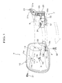
- Fig.1 is an exploded perspective view showing a door mirror assembly for a vehicle according to an embodiment of the present invention.
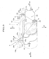
- Fig.2A is a view showing a door mirror assembly as viewed from the rear.
- FIG.2B is a view showing a door mirror assembly as viewed from the bottom.
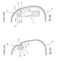
- FIG.3A is a sectional view taken along line IIIA - IIIA in FIG.2A.
- FIG.3B is a sectional view taken along line IIIB - IIIB in FIG.2A.
- FIG.4A is a view showing a frame as viewed from the rear.
- FIG.4B is a view showing a frame as viewed from the bottom.
- FIG.5 is a view showing a mirror assembly as viewed in the direction identified with an arrow C in FIG.2A.
- FIG.6 is a conceptual schematic illustrating the positions of the attachment sections and the engagement sections.
- An embodiment of the present invention is now described with reference to the accompanying drawings.
- As shown in FIGS.1, 2A and 2B, a door mirror assembly for a vehicle according to an embodiment of the present invention includes a door mirror housing (hereinafter referred to as a housing H) and a frame F which supports the housing H internally. The door mirror assembly is mounted on a
mirror base 101 which is provided on the side of avehicle 100, as shown in FIG.2A. The door mirror assembly also includes a mirror (not shown) which is installed in the front aperture of housing H, and accommodates a control sub-assembly (not shown) for controlling the angle of mirror within the housing H. - As shown FIG.1, the housing H includes a
shell 10 made of a synthetic resin, upper andlower attachment ports shell 10 and first andsecond engagement ports shell 10. The positions of the upper andlower attachment ports second engagement ports lower attachment elements second engagement elements - As shown in FIG.1, the
upper attachment port 11 has abearing surface 11a, which is formed on the upper middle part of the inner surface ofshell 10 and ascrew hole 11b drilled into thebearing surface 11a. As shown in FIG.3A, which depicts a cross sectional view taken along line IIIA - IIIA in FIG.2A, an L-shaped portion recessed inwardly into theshell 10 forms theupper attachment port 11. The lower portion ofside surface 11c ofupper attachment port 11 is configured to be part-circular, as shown in FIG.1. - A
lower attachment port 12, which is formed at the bottom ofshell 10, has abearing surface 12a and ascrew hole 12b drilled into the center of thebearing surface 12a. - As shown in FIGS.1 and 2A, the
first engagement port 13 has ahole 13a, which is rectangular and integrally formed with theshell 10. The position offirst engagement port 13 is correlated with that offirst engagement element 23, and thehole 13a is adapted such that its size is appropriate for insertion of aclaw 23b as shown in FIG.5. - As shown in FIGS.1 and 2A, the
second engagement port 14 has ahole 14a, which has a T-shaped section and is formed integrally with theshell 10. The position ofsecond engagement port 14 is correlated with that ofsecond engagement element 24, and thehole 14a is arranged so that the width of its upper portion is larger than that of the lower portion. The width of the upper portion of thehole 14a is adapted such that its size is appropriate for insertion of aclaw 24b as shown in FIG.5. On the other hand, the width of the lower portion is adapted to be same as the thickness of thecolumn 24a shown in FIG.5. - As shown in FIG.4A, the frame F includes a
main body 20, which is made of a synthetic resin and nearly L-shaped as viewed from the side thereof. The upper andlower attachment elements main body 20 and the first andsecond engagement elements main body 20. A drive assembly M is also mounted on themain body 20 for positioning the door mirror assembly in a retracted or operative position. In this connection, a symbol S1 represents a base of shaft for transmitting drive power generated by the drive assembly M. - As shown in FIG.4A, the
upper attachment element 21, which is formed on the upper end ofmain body 20, has a mountingsurface 21a which comes in contact with the bearingsurface 11a of housing H shown in FIG.1 and ascrew hole 21b drilled into the mountingsurface 21a. In the present embodiment, theupper attachment element 21 is located at a thinned portion of the upper end ofmain body 20. Acontact surface 21c ofupper attachment element 21 is adapted to be part-circular, the axis of the circle being substantially perpendicular to the axis P defined by the screw holes 21b and 22b, and comes into contact with theside surface 11c ofupper attachment port 11 shown in FIG.1. - As shown in FIGS.4A and 4B, the
lower attachment element 22, which is formed at the bottom ofmain body 20, has a mountingsurface 22a which contacts thebearing surface 12a of housing H and ascrew hole 22b drilled into the mountingsurface 22a. - As shown in FIG.5, the
first engagement element 23 includes acolumn 23a, which is plate like and formed on the outer surface ofmain body 20, facing theshell 10. - The
column 23a extends beyond the outside surface ofshell 10 through thehole 13a while it is in contact with the side wall ofhole 13a. Thecolumn 23a has aclaw 23b at the end thereof. - A surface of the
claw 23b facing themain body 20 comes in contact with aperiphery 13b ofhole 13a flush with the outer surface ofshell 10. As shown in FIG.4A, theclaw 23b is positioned so that the direction of its width is substantially parallel with the axis P defined by the screw holes 21b and 22b. - As shown in FIG.5, the
second engagement element 24 has acolumn 24a like a brick, and is formed on the outer surface ofmain body 20 facing theshell 10. - The
column 24a extends beyond the outer surface ofshell 10 through thehole 14a while it is in contact with the side wall ofhole 14a. Thecolumn 24a also has aclaw 24b at the end thereof and acontact surface 24c parallel to theclaw 24b in the middle thereof. The distance between the inner (lower) surface ofclaw 24b andcontact surface 24c is adapted to be equal to the thickness of shell 10 (see FIG.5). - A surface of the
claw 24b facing themain body 20 comes into contact with aperiphery 14b ofhole 14a flush with the outer surface ofshell 10. Thecontact surface 24c comes into contact with aperiphery 14c ofhole 14a flush with the inner surface ofshell 10. As shown in FIG.4A, theclaw 24b is positioned so that the direction of its width is substantially parallel with the axis P. - In the present embodiment, the upper and
lower attachment elements second engagement elements main body 20, as shown in FIGs.4A and 4B. This type of arrangement, which enables positioning of the elements in an evenly dispersed manner over themain body 20, allows stable retention of the housing H. - As shown in FIG.6, the
claw 23b ofcolumn 23a and theclaw 24b ofcolumn 24a are positioned on the circumferences of imaginary circles R1 and R2 respectively, the centers of which lie on the axis P defined by the upper andlower attachment elements - A method for fixing a housing H and a frame F is described in detail below.
- As shown in FIG.1, the frame F is mounted at a predetermined position inside the housing H. More specifically, while the base S1 of shaft attached to the frame F is positioned above a shaft hole S2 drilled into the bottom of the
shell 10, thesecond engagement element 24 of frame F is inserted into the upper portion of larger width of thehole 14a so that theclaw 24b shown in FIG.5 reaches the outside ofshell 10. - Next, the frame F is slid diagonally downward, in the Y2 direction shown in FIG.2A, so that the
column 24a is inserted into the smaller width (lower) portion ofhole 14a until it rests on the bottom thereof. In this way, thecolumn 24a andhole 14a are completely engaged. This engaged section is hereinafter referred to as thesecond engagement section 4. As shown in FIG.5, at thesecond engagement section 4, thecolumn 24a comes into contact with both side walls of thehole 14a, and the inner side surface ofclaw 24b facing themain body 20 comes into contact with theperiphery 14b of thehole 14a. Also thecontact surface 24c comes into contact with theother periphery 14c of thehole 14a. In this way, theshell 10 of housing H is interposed between theclaw 24b andcontact surface 24c. Since theclaw 24b ofcolumn 24a is positioned on the circumference of an imaginary circle R2, the center of which lies on an axis P defined byscrew holes second engagement section 4 is accordingly positioned on the same circumference. - As shown in FIGS.2A and 5, the displacement and deformation of the housing H in the directions shown by arrows X1, X2, Z1 and Z2 are restricted, so that the rotational displacement of the housing H about the axis P relative to the frame F, in the directions identified with arrows R21 and R22, is restricted.
- As shown FIG.2A, the displacement and deformation of housing H relative to the frame F in the direction of arrow Y1 is restricted since the
column 24a is inserted into thehole 14a until it rests on the bottom thereof. - As shown in FIG.5, the
hole 13a of housing H and thecolumn 23a of frame F are aligned and the frame F is urged toward the housing H. Thecolumn 23a deforms elastically in order to enter thehole 13a. When theclaw 23b reaches the outside ofshell 10, thecolumn 23a recovers from this elastic deformation and thecolumn 23a andhole 13a are thereby engaged. This engaged section is hereinafter referred to as thefirst engagement section 3. In thefirst engagement section 3, thecolumn 23a comes in contact with a side wall of thehole 13a, and the inner side surface of theclaw 23b facing themain body 20 comes in contact with theperiphery 13b ofhole 13a. Since theclaw 23b ofcolumn 23a is positioned on the circumference of an imaginary circle R1, the center of which lies on the axis P defined by the screw holes 21b and 22b shown in FIG.4A, thefirst engagement section 3 is accordingly positioned on the same circumference. - As shown in FIGS.2A and 5, the displacement and deformation of the housing H in the directions shown by arrows X2 and Z1 are restricted, so that the rotational displacement of the housing H about the axis P relative to the frame F, in the direction identified with an arrow R12, is restricted.
- It is possible to substantially or completely prevent the housing H from rattling relative to the frame F as a result of the retention provided by the first and
second engagement sections first engagement section 3 restricts the rotational displacement of housing H relative to the frame F in the direction identified by the arrow R12 (R22). On the other hand, thesecond engagement section 4 restricts the rotational displacement in the reverse direction identified by the arrow R21 (R11). - As shown in FIGS.3B and 4A, when the housing H and frame F are engaged, the
contact surface 21c ofupper attachment element 21 comes in contact with theside surface 11c ofupper attachment port 11. Since thecontact surface 21c is adapted to be substantially perpendicular to the axis P, the displacement and deformation of housing H relative to the frame F in the direction identified by arrow Y2 are restricted. Also, as described above, since thesecond engagement section 4 restricts the displacement and deformation in the direction of arrow Y1, as shown in FIG.2A, it is consequently possible to restrict the displacement and deformation in the direction of axis P. - As shown in FIG.1, when the housing H and frame F are engaged with each other, the bearing
surface 11a of theupper attachment port 11 comes into contact with the mountingsurface 21a of theupper attachment element 21 and thescrew hole 11b of theupper attachment port 11 and thescrew hole 21b ofupper attachment element 21 are aligned. Similarly, as shown in FIGS. 1 and 4B, the bearingsurface 12a of thelower attachment port 12 comes into contact with the mountingsurface 22a of thelower attachment element 22 and thescrew hole 12b of thelower attachment port 12 and ascrew hole 22b of thelower attachment element 22 are aligned. - As shown in FIG.1, a
fastener 31, such as a screw, is screwed into thescrew hole 11b from the outside of housing H so that theupper attachment port 11 of housing H and theupper attachment element 21 of frame F are attached. This attached section is hereinafter referred to as anupper attachment section 1. Similarly, afasteners 32 is screwed into thescrew hole 12b from the outside of housing H so that thelower attachment port 12 and thelower attachment element 22 are attached. This attached section is hereinafter referred to as alower attachment section 2. - In the door mirror assembly for a vehicle according to the present embodiment, the housing H and frame F are attached to each other by the upper and
lower attachment sections second engagement sections - Although the housing H and frame F are attached at only two locations, adequate attachment strength can be obtained as a result of an appropriate positioning of the first and
second engagement sections second engagement sections lower attachment sections - The housing H, which intrinsically tends to rotate around the axis P relative to the frame F, will not rattle under high attachment strength as a result of the restriction provided by the first and
second engagement sections second engagement sections - It is possible to achieve excellent workability for the steps of assembling the first and
second engagement sections first engagement section 3 is assembled by inserting thecolumn 23a, integrally formed with themain body 20 of frame F, into thehole 13a integrally formed with theshell 10 of housing H. Thesecond engagement section 4 is assembled in the similar manner to that of thefirst engagement section 3. - At least during the assembling of a door mirror assembly, relatively secure attachment of the housing H and frame F, which is realized by simple engagement of these two, can prevent the frame F not only from slipping out of the housing H but also from undergoing displacement, even if there is no mechanical attachment with fasteners. This will lead to excellent workability while the housing H and frame F are attached with
fasteners - The present embodiment, which uses a simple structure for the
holes columns - The minimum use of fasteners for attaching the housing H and frame F allows a reduction in the number of parts and man-hours associated with assembly.
- Since the size and shape of housing H and frame F of the present embodiment represents an example, they may be modified according to the vehicle to which the door mirror assembly is mounted. The construction of each engagement port of housing H and each engagement element of frame F is also not limited to those described in the above embodiment. For example, a claw may be formed on the housing H and a hole drilled into the frame F. Furthermore, although there are two engagement sections in the present embodiment this can be reduced to one, or increased as required.
Claims (5)
- A door mirror assembly for a vehicle comprising:a housing (H), wherein the housing has a shell (10) with a front aperture, two attachment ports (11, 12) formed on the inner surface of shell and an engagement port (13 or 14) formed integrally with the shell;a frame (F) supporting the housing internally, wherein the frame has a main body (20) to be enclosed by the shell (10), two attachment elements (21, 22) formed on the outer surface of the main body and an engagement element (23 or 24) formed integrally with the main body;two attachment sections (1, 2) formed by attaching the two attachment ports and two attachment elements with fasteners (31, 32); andan engagement section (3 or 4) formed by engaging the engagement port with the engagement element,wherein the engagement section is arranged so as to be on the circumference of a circle, and the center of that circle lies on an axis defined by the two attachment sections, so that the rotational displacement of the housing relative to the frame can be restricted.
- A door mirror assembly according to claim 1, wherein at least two engagement sections (3, 4) are provided and the engagement sections restrict the rotational displacement of housing in opposite directions to each other.
- A door mirror assembly according to claim 1 or claim 2, wherein at least one engagement port comprises a hole (13a or 14a) drilled into the shell, and the corresponding engagement element comprises a column (23a or 24a) projecting from the main body, the column having a claw (23b or 24b) at one end thereof, and further wherein the column is adapted to reach beyond the outer surface of the shell through said hole while the column is in contact with a side wall of the hole, and the claw is adapted to be in contact with the periphery of the hole.
- A door mirror assembly according to claim 3, wherein the column has a contact surface (24c) which is adapted to be in contact with the inner surface of shell.
- A door mirror assembly according to claim 3 or claim 4, wherein the claw is adapted to be positioned so that a direction of the width of claw is substantially parallel with said axis.
Applications Claiming Priority (2)
| Application Number | Priority Date | Filing Date | Title |
|---|---|---|---|
| JP2002310622 | 2002-10-25 | ||
| JP2002310622A JP4009177B2 (en) | 2002-10-25 | 2002-10-25 | Vehicle door mirror |
Publications (2)
| Publication Number | Publication Date |
|---|---|
| EP1413483A1 true EP1413483A1 (en) | 2004-04-28 |
| EP1413483B1 EP1413483B1 (en) | 2010-06-30 |
Family
ID=32064376
Family Applications (1)
| Application Number | Title | Priority Date | Filing Date |
|---|---|---|---|
| EP03256544A Expired - Lifetime EP1413483B1 (en) | 2002-10-25 | 2003-10-17 | Door mirror assembly for a vehicle |
Country Status (7)
| Country | Link |
|---|---|
| US (1) | US7048393B2 (en) |
| EP (1) | EP1413483B1 (en) |
| JP (1) | JP4009177B2 (en) |
| KR (1) | KR100528852B1 (en) |
| CN (1) | CN1274533C (en) |
| DE (1) | DE60333152D1 (en) |
| TW (1) | TWI240686B (en) |
Families Citing this family (8)
| Publication number | Priority date | Publication date | Assignee | Title |
|---|---|---|---|---|
| CA2449142A1 (en) * | 2002-11-12 | 2004-05-12 | Magna Donnelly Mirrors North America L.L.C. | Mirror system with interlock attachment for reflective element |
| KR100811949B1 (en) * | 2006-10-30 | 2008-03-10 | 현대자동차주식회사 | Motorized Foldable Outside Mirror Assembly |
| EP2233360B2 (en) * | 2009-03-27 | 2016-07-13 | SMR Patents S.à.r.l. | Snap fit connection in a rear view mirror |
| EP2253510B1 (en) * | 2009-05-19 | 2013-01-02 | SMR Patents S.à.r.l. | Modular Rear View Mirror and Method to assemble it |
| JP5908829B2 (en) * | 2012-11-30 | 2016-04-26 | 株式会社村上開明堂 | door mirror |
| JP6276509B2 (en) * | 2013-03-08 | 2018-02-07 | 株式会社ミツバ | door mirror |
| DE102021203317B3 (en) * | 2021-03-31 | 2022-07-07 | Motherson Innovations Company Limited | Outer rear view mirror assembly for road vehicles, outer rear view mirror mounting system for left and right hand drive road vehicles and method of manufacture |
| JP2024158527A (en) * | 2023-04-27 | 2024-11-08 | 美里工業株式会社 | Vehicle door mirror and manufacturing method thereof |
Citations (3)
| Publication number | Priority date | Publication date | Assignee | Title |
|---|---|---|---|---|
| EP0276677A1 (en) * | 1987-01-13 | 1988-08-03 | Murakami Kaimeido Co., Ltd | Holding device of a mirror element for a rearview mirror |
| EP0433584A1 (en) * | 1989-12-15 | 1991-06-26 | Hohe Kg | External rearview mirror for a vehicle with press-fitted cover |
| EP1116628A2 (en) * | 2000-01-11 | 2001-07-18 | Kabushiki Kaisha Tokai-Rika-Denki-Seisakusho | Vehicle mirror assembly and method for assembling the same |
Family Cites Families (17)
| Publication number | Priority date | Publication date | Assignee | Title |
|---|---|---|---|---|
| US3005385A (en) * | 1957-12-04 | 1961-10-24 | Standard Mirror Co Inc | Remote controlled rear-vision mirror allowing accurate aiming |
| US4988179A (en) * | 1989-04-19 | 1991-01-29 | Navistar International Transportation Corp. | Electromagnetically locking mirror glass adjusting system |
| DE69202664T2 (en) * | 1991-10-04 | 1995-10-19 | Britax Rainsfords Pty Ltd | Drive module for a mirror. |
| US5227924A (en) * | 1992-10-05 | 1993-07-13 | Delbar Products, Inc. | Horizontally adjustable rearview mirror |
| JP3301571B2 (en) | 1993-12-13 | 2002-07-15 | 株式会社東海理化電機製作所 | Visor mounting member of folding door mirror for automobile |
| DE9420273U1 (en) * | 1994-12-17 | 1995-04-06 | Hohe GmbH & Co. KG, 97903 Collenberg | Vehicle exterior mirror |
| JPH08244532A (en) | 1995-01-10 | 1996-09-24 | Ichikoh Ind Ltd | In-vehicle device housing connection structure |
| JPH10100794A (en) | 1996-10-02 | 1998-04-21 | Sakae Riken Kogyo Kk | Vehicle door mirror device |
| JPH10181452A (en) * | 1996-12-26 | 1998-07-07 | Sakae Riken Kogyo Kk | Mirror device for vehicle |
| JP2001294087A (en) | 2000-04-14 | 2001-10-23 | Tokai Rika Co Ltd | Structure for holding visor for door mirror device |
| JP3881153B2 (en) * | 2000-04-25 | 2007-02-14 | 株式会社東海理化電機製作所 | Vehicle door mirror device |
| JP2001322497A (en) * | 2000-05-12 | 2001-11-20 | Tokai Rika Co Ltd | Mirror angle adjustment device |
| US6347872B1 (en) * | 2001-02-20 | 2002-02-19 | Delbar Products Inc. | Snap-in rearview mirror assembly for vehicles |
| US6382805B1 (en) * | 2001-02-28 | 2002-05-07 | Metagal Industria E Comercio Ltda | External rearview mirror |
| JP2002274260A (en) * | 2001-03-19 | 2002-09-25 | Tokai Rika Co Ltd | Assembly structure of vehicle mirror device |
| EP1653092B1 (en) * | 2001-03-19 | 2007-11-28 | Kabushiki Kaisha Tokai-Rika-Denki-Seisakusho | Vehicle mirror device assembly |
| JP3887543B2 (en) * | 2001-03-19 | 2007-02-28 | 株式会社東海理化電機製作所 | Mirror device for vehicle |
-
2002
- 2002-10-25 JP JP2002310622A patent/JP4009177B2/en not_active Expired - Fee Related
-
2003
- 2003-10-03 TW TW092127398A patent/TWI240686B/en active
- 2003-10-08 US US10/680,137 patent/US7048393B2/en not_active Expired - Fee Related
- 2003-10-17 DE DE60333152T patent/DE60333152D1/en not_active Expired - Lifetime
- 2003-10-17 EP EP03256544A patent/EP1413483B1/en not_active Expired - Lifetime
- 2003-10-20 KR KR10-2003-0072940A patent/KR100528852B1/en not_active Expired - Fee Related
- 2003-10-24 CN CNB200310102313XA patent/CN1274533C/en not_active Expired - Fee Related
Patent Citations (3)
| Publication number | Priority date | Publication date | Assignee | Title |
|---|---|---|---|---|
| EP0276677A1 (en) * | 1987-01-13 | 1988-08-03 | Murakami Kaimeido Co., Ltd | Holding device of a mirror element for a rearview mirror |
| EP0433584A1 (en) * | 1989-12-15 | 1991-06-26 | Hohe Kg | External rearview mirror for a vehicle with press-fitted cover |
| EP1116628A2 (en) * | 2000-01-11 | 2001-07-18 | Kabushiki Kaisha Tokai-Rika-Denki-Seisakusho | Vehicle mirror assembly and method for assembling the same |
Also Published As
| Publication number | Publication date |
|---|---|
| JP2004142635A (en) | 2004-05-20 |
| JP4009177B2 (en) | 2007-11-14 |
| CN1274533C (en) | 2006-09-13 |
| US7048393B2 (en) | 2006-05-23 |
| US20040080840A1 (en) | 2004-04-29 |
| KR100528852B1 (en) | 2005-11-15 |
| TW200406323A (en) | 2004-05-01 |
| KR20040036563A (en) | 2004-04-30 |
| EP1413483B1 (en) | 2010-06-30 |
| TWI240686B (en) | 2005-10-01 |
| CN1498794A (en) | 2004-05-26 |
| DE60333152D1 (en) | 2010-08-12 |
Similar Documents
| Publication | Publication Date | Title |
|---|---|---|
| CN103516128B (en) | motor driver | |
| US6329735B1 (en) | Commutator motor | |
| EP1413483B1 (en) | Door mirror assembly for a vehicle | |
| KR100948106B1 (en) | motor | |
| JP2001271918A (en) | Drive for automatic transmission | |
| JP2002044909A (en) | Geared motor | |
| US20040164634A1 (en) | Ambidextrous electronic window lift motor | |
| US6158302A (en) | Torque support | |
| KR20250132531A (en) | Modular electric axle assembly for banjo-type housing | |
| CN101096949A (en) | Motor/pump unit | |
| US20180065471A1 (en) | Mounting device for cooling module of vehicle | |
| US20250129795A1 (en) | Fan for generating a cooling air flow, comprising an elastic damping element for damping a transmission of vibrations | |
| WO2024241898A1 (en) | Wheel cap | |
| JP4968531B2 (en) | Electromagnetic clutch | |
| KR100506334B1 (en) | A rear shelf trim for a car | |
| JPH09164881A (en) | Car door mirror | |
| JP2008074362A (en) | Mounting structure between body panel and mounting parts for automobile, and mounting structure between rocker panel and rocker protector | |
| JP2007023939A (en) | Electric pump, electric pump mounting structure, and bracket combined with electric pump | |
| KR100361279B1 (en) | A fixing structure of radiator for vehicle | |
| CN101278178A (en) | Electric Steering Equipment | |
| JPH0528930Y2 (en) | ||
| KR100461363B1 (en) | transmission mounting bracket of vehicle | |
| CN119860421A (en) | Gear ring assembly and bridge driving system | |
| KR200297566Y1 (en) | Grommet to attachment rear shalf trim of a car | |
| KR200156387Y1 (en) | Brush holder of motor |
Legal Events
| Date | Code | Title | Description |
|---|---|---|---|
| PUAI | Public reference made under article 153(3) epc to a published international application that has entered the european phase |
Free format text: ORIGINAL CODE: 0009012 |
|
| 17P | Request for examination filed |
Effective date: 20031107 |
|
| AK | Designated contracting states |
Kind code of ref document: A1 Designated state(s): AT BE BG CH CY CZ DE DK EE ES FI FR GB GR HU IE IT LI LU MC NL PT RO SE SI SK TR |
|
| AX | Request for extension of the european patent |
Extension state: AL LT LV MK |
|
| 17Q | First examination report despatched |
Effective date: 20040907 |
|
| AKX | Designation fees paid |
Designated state(s): DE FR GB IT |
|
| GRAP | Despatch of communication of intention to grant a patent |
Free format text: ORIGINAL CODE: EPIDOSNIGR1 |
|
| GRAS | Grant fee paid |
Free format text: ORIGINAL CODE: EPIDOSNIGR3 |
|
| GRAA | (expected) grant |
Free format text: ORIGINAL CODE: 0009210 |
|
| AK | Designated contracting states |
Kind code of ref document: B1 Designated state(s): DE FR GB IT |
|
| REG | Reference to a national code |
Ref country code: GB Ref legal event code: FG4D |
|
| REF | Corresponds to: |
Ref document number: 60333152 Country of ref document: DE Date of ref document: 20100812 Kind code of ref document: P |
|
| PG25 | Lapsed in a contracting state [announced via postgrant information from national office to epo] |
Ref country code: IT Free format text: LAPSE BECAUSE OF FAILURE TO SUBMIT A TRANSLATION OF THE DESCRIPTION OR TO PAY THE FEE WITHIN THE PRESCRIBED TIME-LIMIT Effective date: 20100630 |
|
| PLBE | No opposition filed within time limit |
Free format text: ORIGINAL CODE: 0009261 |
|
| STAA | Information on the status of an ep patent application or granted ep patent |
Free format text: STATUS: NO OPPOSITION FILED WITHIN TIME LIMIT |
|
| 26N | No opposition filed |
Effective date: 20110331 |
|
| GBPC | Gb: european patent ceased through non-payment of renewal fee |
Effective date: 20101017 |
|
| REG | Reference to a national code |
Ref country code: DE Ref legal event code: R097 Ref document number: 60333152 Country of ref document: DE Effective date: 20110330 |
|
| PG25 | Lapsed in a contracting state [announced via postgrant information from national office to epo] |
Ref country code: FR Free format text: LAPSE BECAUSE OF NON-PAYMENT OF DUE FEES Effective date: 20101102 |
|
| REG | Reference to a national code |
Ref country code: FR Ref legal event code: ST Effective date: 20110630 |
|
| PG25 | Lapsed in a contracting state [announced via postgrant information from national office to epo] |
Ref country code: GB Free format text: LAPSE BECAUSE OF NON-PAYMENT OF DUE FEES Effective date: 20101017 |
|
| PGFP | Annual fee paid to national office [announced via postgrant information from national office to epo] |
Ref country code: DE Payment date: 20121010 Year of fee payment: 10 |
|
| REG | Reference to a national code |
Ref country code: DE Ref legal event code: R119 Ref document number: 60333152 Country of ref document: DE Effective date: 20140501 |
|
| PG25 | Lapsed in a contracting state [announced via postgrant information from national office to epo] |
Ref country code: DE Free format text: LAPSE BECAUSE OF NON-PAYMENT OF DUE FEES Effective date: 20140501 |