EP1411684A2 - Programmable inter-packet gap generator with byte granularity - Google Patents
Programmable inter-packet gap generator with byte granularity Download PDFInfo
- Publication number
- EP1411684A2 EP1411684A2 EP03023255A EP03023255A EP1411684A2 EP 1411684 A2 EP1411684 A2 EP 1411684A2 EP 03023255 A EP03023255 A EP 03023255A EP 03023255 A EP03023255 A EP 03023255A EP 1411684 A2 EP1411684 A2 EP 1411684A2
- Authority
- EP
- European Patent Office
- Prior art keywords
- packet
- inter
- tokens
- token bucket
- gap
- Prior art date
- Legal status (The legal status is an assumption and is not a legal conclusion. Google has not performed a legal analysis and makes no representation as to the accuracy of the status listed.)
- Granted
Links
Images

Classifications
-
- H—ELECTRICITY
- H04—ELECTRIC COMMUNICATION TECHNIQUE
- H04L—TRANSMISSION OF DIGITAL INFORMATION, e.g. TELEGRAPHIC COMMUNICATION
- H04L47/00—Traffic control in data switching networks
- H04L47/10—Flow control; Congestion control
- H04L47/28—Flow control; Congestion control in relation to timing considerations
- H04L47/286—Time to live
-
- H—ELECTRICITY
- H04—ELECTRIC COMMUNICATION TECHNIQUE
- H04L—TRANSMISSION OF DIGITAL INFORMATION, e.g. TELEGRAPHIC COMMUNICATION
- H04L47/00—Traffic control in data switching networks
- H04L47/10—Flow control; Congestion control
Definitions
- the present invention relates to network devices that allow for data to be routed and moved in data communication or computer networks.
- the present invention further relates to high-speed network devices, such as network switches, routers, and repeaters. More specifically, the present invention is directed to methods and apparatuses that allow the speed of network traffic through the network device to be flexibly tuned with good granularity.
- the 10 Gigabit Media Independent Interface (XGMII) is specified in the IEEE Draft P802.3ae (Ethernet standard specification for 10 Gigabit per second) to interface between IEEE 802.3 MAC entities and Physical Layer entities.
- the data bus width of XGMII is 32 bits (4 bytes) when applied on a double-edge clock or 64 bits (8 bytes) on a single-edge clock.
- the specification also discusses the value for the Inter-Packet Gap (IPG), where the IPG is the gap between two packets transmitted on an Ethernet network.
- the IPG value that is defined by the IEEE 802.3 standard is 12 bytes. However, the packet length is variable, so the last byte of the packet data can fall on any byte of a 4/8 byte bus.
- the IEEE standard requires that the start frame delimiter must be placed at the location of byte 0. This has the effect that the IPG value cannot be fixed at a predefined value.
- the solution to fulfill the 12-byte IPG requirement by the IEEE 802.3 specification on the XGMII Interface is to have the IPG value vary in a range depending on the packet size, so that the average value will be proximate to the predefined value.
- packets with the size of a multiple of eight plus one (8*n +1) have the fixed IPG value of 15 bytes, etc. Therefore, if the packet size is evenly distributed in the range of (8*n) to (8*n + 7) for a long period of time, then the average IPG value will become 12 bytes.
- packet sizes are not evenly distributed in many real applications. For instance, if most of packets have the size of 65 (8*n +1) bytes, then the average IPG will be approaching 15 bytes instead of 12 bytes. In order to solve this problem, a better way is needed to smooth out the IPG value to a predefined value for any combination of packet sizes.
- Another example illustrating the need for a finer granularity in the IPG occurs when the IPG needs to be smaller than 12 bytes and not be a multiple of four.
- the 8-byte packet header preamble and start frame delimiter
- some packet information such as packet length, VLAN ID, service class, etc. It is possible that the replaced packet information is larger than 8 bytes and then IPG size will become less than 12 bytes to maintain the same traffic speed.
- the present invention is directed to methods and apparatuses that employ a token bucket scheme to program the length of the IPG and to provide granularity to the IPG that is less than four bytes.
- the IPG Generator checks the number of tokens in the bucket, where the tokens represent bytes. If there are not enough tokens, then more bytes of IPG will be inserted and tokens will be added to the bucket. Otherwise, fewer bytes of IPG will be inserted and tokens will be taken out from the bucket. Since the bus width is 4/8 bytes and the start of frame delimiter must be placed at the byte 0, the number of inserted bytes for additional IPG is always the multiple of 4 or 8.
- a process of generating an inter-packet gap in a network device is disclosed. First, it is determined whether a next packet is available to forward from a packet buffer. The number of tokens contained in a token bucket is checked and bytes are added to the inter-packet gap and tokens are added to the token bucket, when the number of tokens contained in a token bucket is less than a predetermined number of tokens. Otherwise, the size of the inter-packet gap is reduced and tokens are taken out of the token bucket, when the number of tokens contained in a token bucket is greater than or equal to the predetermined number of tokens. Thereafter, the inter-packet gap is supplied and sent with the next packet over an interface between the network device and a network.
- the process can supply the inter-packet gap to be sent with the next packet over the interface, where the interface has a bus width greater than or equal to thirty-two bits.
- the process of generating the inter-packet gap in the network device may be performed when an end of packet indicator of a previous packet is received or for every cycle of a clock coordinating the performance of the network device.
- the step of adding bytes to the inter-packet gap can include adding bytes that are a multiple of one of four or eight bytes to the inter-packet gap.
- the steps of adding tokens to the token bucket and taking tokens out of the token bucket can be performed in conjunction with a packet length evaluation of the next packet and a number of tokens added to and subtracted from is determined with respect to the packet length evaluation.
- the process of generating the inter-packet gap in the network device may be performed such that a series of inter-packet gaps generated are shaped such that an average value for the series of inter-packet gaps approaches a predefined inter-packet gap value.
- an inter-packet gap generator for a network device.
- the generator includes determining means for determining whether a next packet is available to forward from a packet buffer and checking means for checking a number of tokens contained in a token bucket.
- the generator also includes adding means for adding bytes to the inter-packet gap and adding tokens to the token bucket, when the number of tokens contained in a token bucket is less than a predetermined number of tokens and reducing means for reducing a size of the inter-packet gap and taking tokens out of the token bucket, when the number of tokens contained in a token bucket is greater than or equal to the remainder of the packet length plus the predefined IPG divided by the BC value.
- the generator also includes supplying means for supplying the inter-packet gap to be sent with the next packet over an interface between the network device and a network.
- an inter-packet gap generator for a network device.
- the generator includes an evaluator for determining whether a next packet is available to forward from a packet buffer and a checker for checking a number of tokens contained in a token bucket.
- the generator also includes an inserter for adding bytes to the inter-packet gap and adding tokens to the token bucket, when the number of tokens contained in a token bucket is less than a predetermined number of tokens and a reducer for reducing a size of the inter-packet gap and taking tokens out of the token bucket, when the number of tokens contained in a token bucket is greater than or equal to the remainder of the packet length plus the predefined IPG divided by the BC value.
- the generator has a supplier for supplying the inter-packet gap to be sent with the next packet over an interface between the network device and a network.
- a process of generating an inter-packet gap in a network device comprising:
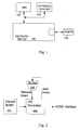
- Fig. 1 is a general block diagram of a network device and associated modules for use with the present invention
- Fig. 2 illustrates a general block diagram of a programmable IPG generator, according to one embodiment of the present invention
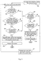
- Fig. 3 illustrates a flowchart of the process of generating a proper IPG, according to one embodiment of the present invention.
- Fig. 4 illustrates a general block diagram of a network device having a programmable IPG generator, according to one embodiment of the present invention.
- the present invention provides a solution to the problem of achieving a proper value for the IPG to comply with various requirements, such as the IEEE 802.3ae standard.
- the use of the token and bucket mechanism allows for the amount of the IPG to be finely tuned and allows for greater performance of the network for packets of various sizes.
- the general process of tuning the IPG is discussed first, an algorithm capable of performing the process of the present invention, according to one embodiment, is discussed and then several illustrative examples are provided for several different scenarios.
- Fig. 1 illustrates a configuration of a node of the network, in accordance with one embodiment of the present invention.
- the network device 101 is connected to or in communication with a Central Processing Unit (CPU) 102 and other external devices 103.
- the CPU can be used as necessary to program the network device 101 with rules that are appropriate to control packet processing.
- the network device 101 should be able to process data received through physical ports 104 with minimal interaction with the CPU and operate, as much as possible, in a free running manner.
- Fig. 2 illustrates a general block diagram of a programmable IPG generator, according to one embodiment of the present invention.
- a packet buffer 201 receives a packet for transmission from the network device. The packet data is forwarded through the IPG generator 202 so that a proper IPG can be determined. As discussed above, the IPG generator makes use of a bucket 203 that contains tokens. When the End of Packet is received and the next packet is available to forward, the IPG Generator checks the number of tokens in the bucket. If there are not enough tokens, then more bytes of IPG will be inserted and tokens will be added to the bucket. Otherwise, fewer bytes of IPG will be inserted and tokens will be taken out from the bucket. The IPG is executed through the XGMII interface, followed by the next packet that was available to be forwarded.
- IPG_p represents a predefined IPG value, where its value is programmable in units of bytes.
- BC represents the number of bytes per cycle that is programmable and can be 4 or 8, based on the width of the bus and the application of the clock in the XGMII interface, according to this embodiment of the invention.
- IPG_c represents the current IPG count and IPG_r represents the remaining IPG bytes in the current cycle.
- PL represents the length of the packet and TC represents the token count.
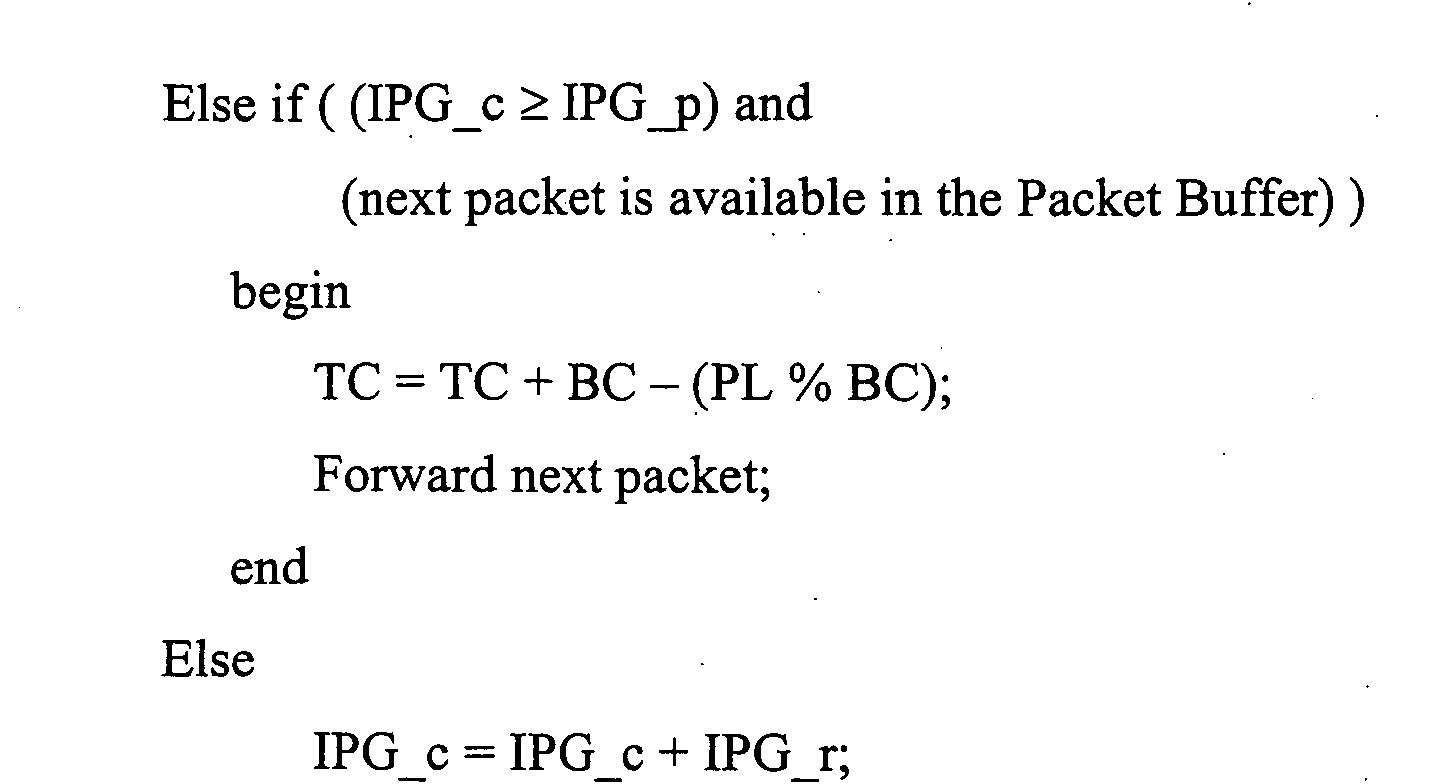
- the pseudo code representation is: It is noted that the % operator represents the modulus operator, such that n % m presents the remainder left over when n is divided by m.
- step 300 for every Start of Packet, the current IPG count is set to zero. Then, in step 301, for every cycle at and after the End of Packet is received, the process proceeds to step 302.
- step 302 it is determined whether a predefined IPG value less the current IPG count is less than the BC value. If the former is true, i.e. the response to the question posed in step 302 is yes, then, in step 303, it is determined whether the token count is greater than or equal to remainder left over from the division of the packet length plus the predefined IPG value by the BC value.
- step 303 it is determined whether the next packet is available in the packet buffer, in step 304. If any of the above evaluations, steps 302, 303 or 304, are false, then the flow breaks off to step 307. If all of the above evaluations, steps 302, 303 or 304, are true, then the token count is decreased by the remainder left over from the division of the packet length plus the predefined IPG value divided by the BC value, in step 305. Thereafter, the next packet in the packet buffer is forwarded, step 306. The process ends until a new Start of Packet is received.
- step 307 it is determined whether the current IPG is greater than or equal to the predefined IPG. If the statement in step 307 is true, the process proceeds to step 308, where it is determined whether the next packet is available in the packet buffer. If the next packet is available, then the token count is increased by BC, less the remainder of the packet length divided by the BC value. Thereafter, in step 310, the packet is forwarded. However, if either of the evaluations in steps 307 and 308 is not true, the flow passes to step 311, where the current IPG count is increased by the remaining bytes in the current cycle. Thereafter, the process continues with step 301 and the remaining process steps are evaluated again.
- the predetermined IPG is set to 12 bytes and the XGMII bus width is 32 bits.
- the following table shows 8 cases. Each case exemplifies the sequence of IPG values when packets with the fixed sizes of 64, 65, 66, 67, 68, 69, 70, 71 bytes, are being transmitted, respectively: Packet Size (bytes) Sequence of IPG 64 12, 12, 12, 12, 12, briefly 65 15, 11, 11, 11, briefly 66 14, 10, 14, 10, briefly 67 13, 13, 13, 9, .................. 68 12, 12, 12, 12, 12, ; 69 15, 11, 11, 11, Across 70 14, 10, 14, 10, .... 71 13, 13, 13, 9, .
- the predetermined IPG is set to 13 bytes and the XGMII bus width is 32 bits.
- the sequence of IPG values when packets with the fixed sizes of 64, 65, 66, 67, 68, 69, 70, 71 bytes, are being transmitted, respectively: Packet Size (bytes) Sequence of IPG 64 16, 12, 12, 12, briefly 65 15, 11, 15, 11, briefly 66 14, 14, 14, 10, ; 67 13, 13, 13, 13, across 68 16, 12, 12, 12, 12, briefly 69 15, 11, 15, 11, fig 70 14, 14, 14, 10, briefly 71 13, 13, 13, 13, premises
- the predetermined IPG is set to 12 bytes and the XGMII bus width is 64 bits.
- the following table illustrates the case with packets having sizes incremented from 64 bytes to 71 bytes : Packet Size (bytes) Token Count Sequence of IPG 64 4 16 65 7 15 66 1 6 67 2 13 68 2 12 69 1 11 70 7 18 71 4 9 64 0 8 65 3 15 66 5 14 67 6 13 68 6 12 69 5 11 70 3 10 71 0 9
- the present invention allows the IPG generator to provide an IPG that takes into account varying combination of packet sizes. Additionally, the present invention also allows the IPG generator to be programmable to a finer granularity to the value of the IPG. Also, while the present invention has been discussed with respect to use with an XGMII, it is also applicable to other bus interfaces having wide widths.
- the network device 401 is illustrated as having an IPG generator 406 in communication with a packet buffer 405 and a port interface 402.
- the port interface 402 is in communication with the ports 404 that provide connections to the larger network.
- Logical portions of the IPG generator 406 include the evaluator 407 in communication with the supplier 412 and the checker 408.
- the checker 408 checks the level of tokens in the bucket 411, with the inserter 409 and the reducer 410, adding or subtracting, respectively, from the number of tokens in the bucket 411.
- the checker is also in communication with the supplier 412, that supplies the IPG to be executed with the next packet available in the packet buffer 405.
- the above-discussed configuration of the invention is, in one embodiment, embodied on a semiconductor substrate, such as silicon, with appropriate semiconductor manufacturing techniques and based upon a circuit layout which would, based upon the embodiments discussed above, be apparent to those skilled in the art.
- a person of skill in the art with respect to semiconductor design and manufacturing would be able to implement the various modules, interfaces, and components, etc. of the present invention onto a single semiconductor substrate, based upon the architectural description discussed above. It would also be within the scope of the invention to implement the disclosed elements of the invention in discrete electronic components, thereby taking advantage of the functional aspects of the invention without maximizing the advantages through the use of a single semiconductor substrate.
- packet has been used in the description of the present invention, the invention has import to many types of network data.
- packet includes packet, cell, frame, datagram, bridge protocol data unit packet, and packet data.
Landscapes
- Engineering & Computer Science (AREA)
- Computer Networks & Wireless Communication (AREA)
- Signal Processing (AREA)
- Data Exchanges In Wide-Area Networks (AREA)
Abstract
Description
| Packet size, multiples of: | IPG |
| 8*n + 1 | 15 bytes |
| 8*n + 2 | 14 bytes |
| 8*n + 3 | 13 bytes |
| 8*n + 4 | 12 bytes |
| 8*n + 5 | 11 bytes |
| 8*n + 6 | 10 bytes |
| 8*n + 7 | 9 bytes |
| 8*n | 8 or 16 bytes |
According to an aspect of the invention, a process of generating an inter-packet gap in a network device is provided, said process comprising:
Advantageously, said process of generating the inter-packet gap in the network device is performed when an end of packet indicator of a previous packet is received.
Advantageously, said process of generating the inter-packet gap in the network device is performed for every cycle of a clock coordinating the performance of the network device.
Advantageously, said step of adding bytes to the inter-packet gap comprises adding bytes that are a multiple of one of four and eight bytes to the inter-packet gap.
Advantageously, said steps of adding tokens to said token bucket and taking tokens out of said token bucket are performed in conjunction with a packet length evaluation of said next packet and a number of tokens added to and subtracted from is determined with respect to said packet length evaluation.
Advantageously, said process of generating the inter-packet gap in the network device is performed such that a series of inter-packet gaps generated are shaped such that an average value for said series of inter-packet gaps approaches a predefined inter-packet gap value.
According to another aspect of the invention, an inter-packet gap generator for a network device is provided, said inter-packet gap generator comprising:
- determining means for determining whether a next packet is available to forward from a packet buffer;
- checking means for checking a number of tokens contained in a token bucket;
- adding means for adding bytes to the inter-packet gap and adding tokens to the token bucket, when the number of tokens contained in the token bucket is less than a predetermined number of tokens;
- reducing means for reducing a size of the inter-packet gap and taking tokens out of the token bucket, when the number of tokens contained in the token bucket is greater than or equal to the predetermined number of tokens; and
- supplying means for supplying the inter-packet gap to be executed with said next packet over an interface between the network device and a network.
Advantageously, said inter-packet gap generator further comprises evaluating means for evaluating when an end of packet indicator of a previous packet is received and said determining means is configured to determine whether the next packet is available to forward from the packet buffer when the evaluating means determines that the end of packet indicator of a previous packet has been received.
Advantageously, said inter-packet gap generator further comprises evaluating means for evaluating when a cycle of a clock coordinating the performance of the network device has elapsed and said determining means is configured to determine whether the next packet is available to forward from the packet buffer when the evaluating means determines that the cycle of a clock coordinating the performance of the network device has elapsed.
Advantageously, said adding means for adding bytes to the inter-packet gap comprises adding means for adding bytes that are a multiple of one of four and eight bytes to the inter-packet gap.
Advantageously, the inter-packet gap generator further comprises a packet length evaluation means for evaluating the packet length of said next packet and wherein said adding means and said reducing means are configured to select a number of tokens added to and subtracted from said token bucket determined with respect to said packet length.
Advantageously, said inter-packet gap generator is configured to generate a series of inter-packet gaps shaped such that an average value for said series of inter-packet gaps approaches a predefined inter-packet gap value.
According to another aspect of the invention, an inter-packet gap generator for a network device is provided, said inter-packet gap generator comprising:
- an evaluator for determining whether a next packet is available to forward from a packet buffer;
- a checker for checking a number of tokens contained in a token bucket;
- an inserter for adding bytes to the inter-packet gap and adding tokens to the token bucket, when the number of tokens contained in the token bucket is less than a predetermined number of tokens;
- a reducer for reducing a size of the inter-packet gap and taking tokens out of the token bucket, when the number of tokens contained in the token bucket is greater than or equal to the predetermined number of tokens; and
- a supplier for supplying the inter-packet gap to be executed with said next packet over an interface between the network device and a network.
Advantageously, said inter-packet gap generator further comprises an end of packet evaluator for evaluating when an end of packet indicator of a previous packet is received and said evaluator is configured to determine whether the next packet is available to forward from the packet buffer when the end of packet evaluator determines that the end of packet indicator of a previous packet has been received.
Advantageously, said inter-packet gap generator further comprises a clock cycle evaluator for evaluating when a cycle of a clock coordinating the performance of the network device has elapsed and said evaluator is configured to determine whether the next packet is available to forward from the packet buffer when the clock cycle evaluator determines that the cycle of a clock coordinating the performance of the network device has elapsed.
Advantageously, said inserter comprises an inserter for adding bytes that are a multiple of one of four or eight bytes to the inter-packet gap.
Advantageously, the inter-packet gap generator further comprises a packet length evaluator for evaluating the packet length of said next packet and wherein the inserter and the reducer are configured to select a number of tokens added to and subtracted from said token bucket determined with respect to said packet length.
Advantageously, said inter-packet gap generator is configured to generate a series of inter-packet gaps shaped such that an average value for said series of inter-packet gaps approaches a predefined inter-packet gap value.

| Packet Size (bytes) | Sequence of IPG |
| 64 | 12, 12, 12, 12, ................ |
| 65 | 15, 11, 11, 11, ................ |
| 66 | 14, 10, 14, 10, ................ |
| 67 | 13, 13, 13, 9, .................. |
| 68 | 12, 12, 12, 12, ..... |
| 69 | 15, 11, 11, 11, ..... |
| 70 | 14, 10, 14, 10, ..... |
| 71 | 13, 13, 13, 9, ..... |
| Packet Size (bytes) | Sequence of IPG |
| 64 | 16, 12, 12, 12, ................ |
| 65 | 15, 11, 15, 11, ................ |
| 66 | 14, 14, 14, 10, ..... |
| 67 | 13, 13, 13, 13,..... |
| 68 | 16, 12, 12, 12, ................ |
| 69 | 15, 11, 15, 11, ................ |
| 70 | 14, 14, 14, 10, ................ |
| 71 | 13, 13, 13, 13, ................ |
| Packet Size (bytes) | Token Count | Sequence of IPG |
| 64 | 4 | 16 |
| 65 | 7 | 15 |
| 66 | 1 | 6 |
| 67 | 2 | 13 |
| 68 | 2 | 12 |
| 69 | 1 | 11 |
| 70 | 7 | 18 |
| 71 | 4 | 9 |
| 64 | 0 | 8 |
| 65 | 3 | 15 |
| 66 | 5 | 14 |
| 67 | 6 | 13 |
| 68 | 6 | 12 |
| 69 | 5 | 11 |
| 70 | 3 | 10 |
| 71 | 0 | 9 |
Claims (10)
- A process of generating an inter-packet gap in a network device, said process comprising:determining whether a next packet is available to forward from a packet buffer;checking a number of tokens contained in a token bucket;adding bytes to the inter-packet gap and adding tokens to the token bucket, when the number of tokens contained in the token bucket is less than a predetermined number of tokens;reducing a size of the inter-packet gap and taking tokens out of the token bucket, when the number of tokens contained in the token bucket is greater than or equal to the predetermined number of tokens; andsupplying the inter-packet gap to be executed with said next packet over an interface between the network device and a network.
- A process as recited in claim 1, wherein said step of supplying the inter-packet gap comprises supplying the inter-packet gap to be executed with said next packet over said interface, where said interface has a bus width greater than or equal to thirty-two bits.
- A process as recited in claim 1, wherein said process of generating the inter-packet gap in the network device is performed when an end of packet indicator of a previous packet is received.
- A process as recited in claim 1, wherein said process of generating the inter-packet gap in the network device is performed for every cycle of a clock coordinating the performance of the network device.
- An inter-packet gap generator for a network device, said inter-packet gap generator comprising:determining means for determining whether a next packet is available to forward from a packet buffer;checking means for checking a number of tokens contained in a token bucket;adding means for adding bytes to the inter-packet gap and adding tokens to the token bucket, when the number of tokens contained in the token bucket is less than a predetermined number of tokens;reducing means for reducing a size of the inter-packet gap and taking tokens out of the token bucket, when the number of tokens contained in the token bucket is greater than or equal to the predetermined number of tokens; andsupplying means for supplying the inter-packet gap to be executed with said next packet over an interface between the network device and a network.
- An inter-packet gap generator as recited in claim 5, wherein said supplying means for supplying the inter-packet gap comprises supplying means for supplying the inter-packet gap to be executed with said next packet over said interface, where said interface has a bus width greater than or equal to thirty-two bits.
- An inter-packet gap generator as recited in claim 5, wherein said inter-packet gap generator further comprises evaluating means for evaluating when an end of packet indicator of a previous packet is received and said determining means is configured to determine whether the next packet is available to forward from the packet buffer when the evaluating means determines that the end of packet indicator of a previous packet has been received.
- An inter-packet gap generator for a network device, said inter-packet gap generator comprising:an evaluator for determining whether a next packet is available to forward from a packet buffer;a checker for checking a number of tokens contained in a token bucket;an inserter for adding bytes to the inter-packet gap and adding tokens to the token bucket, when the number of tokens contained in the token bucket is less than a predetermined number of tokens;a reducer for reducing a size of the inter-packet gap and taking tokens out of the token bucket, when the number of tokens contained in the token bucket is greater than or equal to the predetermined number of tokens; anda supplier for supplying the inter-packet gap to be executed with said next packet over an interface between the network device and a network.
- An inter-packet gap generator as recited in claim 8, wherein said supplier comprises a supplier for supplying the inter-packet gap to be executed with said next packet over said interface, where said interface has a bus width greater than or equal to thirty-two bits.
- An inter-packet gap generator as recited in claim 8, wherein said inter-packet gap generator further comprises an end of packet evaluator for evaluating when an end of packet indicator of a previous packet is received and said evaluator is configured to determine whether the next packet is available to forward from the packet buffer when the end of packet evaluator determines that the end of packet indicator of a previous packet has been received.
Applications Claiming Priority (2)
| Application Number | Priority Date | Filing Date | Title |
|---|---|---|---|
| US10/269,988 US7184404B2 (en) | 2002-10-15 | 2002-10-15 | Programmable inter-packet gap generator with byte granularity |
| US269988 | 2002-10-15 |
Publications (3)
| Publication Number | Publication Date |
|---|---|
| EP1411684A2 true EP1411684A2 (en) | 2004-04-21 |
| EP1411684A3 EP1411684A3 (en) | 2005-06-15 |
| EP1411684B1 EP1411684B1 (en) | 2010-08-25 |
Family
ID=32042893
Family Applications (1)
| Application Number | Title | Priority Date | Filing Date |
|---|---|---|---|
| EP03023255A Expired - Lifetime EP1411684B1 (en) | 2002-10-15 | 2003-10-14 | Inter-packet gap generator for a network device and corresponding process |
Country Status (3)
| Country | Link |
|---|---|
| US (1) | US7184404B2 (en) |
| EP (1) | EP1411684B1 (en) |
| DE (1) | DE60333891D1 (en) |
Cited By (3)
| Publication number | Priority date | Publication date | Assignee | Title |
|---|---|---|---|---|
| FR2925249A1 (en) * | 2007-12-12 | 2009-06-19 | Nexter Systems Sa | METHOD FOR CONTROLLING DATA TRAFFIC AND DEVICE IMPLEMENTING SUCH A METHOD |
| CN102082693A (en) * | 2011-02-15 | 2011-06-01 | 中兴通讯股份有限公司 | Method and device for monitoring network traffic |
| EP2800009A4 (en) * | 2011-12-28 | 2015-09-09 | Fujitsu Ltd | COMPUTER SYSTEM, COMMUNICATION CONTROL DEVICE, AND CONTROL METHOD FOR COMPUTER SYSTEM |
Families Citing this family (24)
| Publication number | Priority date | Publication date | Assignee | Title |
|---|---|---|---|---|
| US7593431B1 (en) * | 2002-05-09 | 2009-09-22 | Marvell International Ltd. | Method and system for monitoring a MAC extra IPG count and adjusting the PHY transmit IPG |
| US7590135B2 (en) * | 2002-12-30 | 2009-09-15 | Intel Corporation | Methods and apparatus to perform security related operations on received signals |
| DE10306293B4 (en) * | 2003-02-14 | 2006-08-31 | Siemens Ag | Method for transmission bandwidth allocation in a packet-oriented communication device |
| KR100689469B1 (en) * | 2003-10-14 | 2007-03-08 | 삼성전자주식회사 | Real-time Multimedia Data Transmission over Ethernet Network |
| US7366866B2 (en) * | 2003-10-30 | 2008-04-29 | Hewlett-Packard Development Company, L.P. | Block size allocation in copy operations |
| US7577096B2 (en) * | 2005-02-18 | 2009-08-18 | Broadcom Corporation | Timestamp metering and rollover protection in a network device |
| US7529191B2 (en) * | 2005-02-18 | 2009-05-05 | Broadcom Corporation | Programmable metering behavior based on table lookup |
| US8379676B1 (en) * | 2006-06-01 | 2013-02-19 | World Wide Packets, Inc. | Injecting in-band control messages without impacting a data rate |
| US7675945B2 (en) | 2006-09-25 | 2010-03-09 | Futurewei Technologies, Inc. | Multi-component compatible data architecture |
| US7961751B2 (en) | 2006-09-25 | 2011-06-14 | Futurewei Technologies, Inc. | Multiplexed data stream timeslot map |
| US7986700B2 (en) * | 2006-09-25 | 2011-07-26 | Futurewei Technologies, Inc. | Multiplexed data stream circuit architecture |
| US8976796B2 (en) | 2006-09-25 | 2015-03-10 | Futurewei Technologies, Inc. | Bandwidth reuse in multiplexed data stream |
| US8340101B2 (en) | 2006-09-25 | 2012-12-25 | Futurewei Technologies, Inc. | Multiplexed data stream payload format |
| US7813271B2 (en) * | 2006-09-25 | 2010-10-12 | Futurewei Technologies, Inc. | Aggregated link traffic protection |
| US8660152B2 (en) * | 2006-09-25 | 2014-02-25 | Futurewei Technologies, Inc. | Multi-frame network clock synchronization |
| US7809027B2 (en) * | 2006-09-25 | 2010-10-05 | Futurewei Technologies, Inc. | Network clock synchronization floating window and window delineation |
| US8295310B2 (en) | 2006-09-25 | 2012-10-23 | Futurewei Technologies, Inc. | Inter-packet gap network clock synchronization |
| US8494009B2 (en) * | 2006-09-25 | 2013-07-23 | Futurewei Technologies, Inc. | Network clock synchronization timestamp |
| US8588209B2 (en) * | 2006-09-25 | 2013-11-19 | Futurewei Technologies, Inc. | Multi-network compatible data architecture |
| CN101578794B (en) * | 2007-01-26 | 2012-12-12 | 华为技术有限公司 | Data communication devices and network components |
| CN102739531B (en) * | 2012-06-19 | 2016-06-15 | 华为技术有限公司 | Flow shaping method and traffic shaping device |
| US9628396B2 (en) * | 2013-07-11 | 2017-04-18 | Mediatek Inc. | Network device and method for outputting data to bus with data bus width at each cycle by generating end of packet and start of packet at different cycles |
| CN104283818B (en) * | 2013-07-11 | 2017-10-27 | 联发科技股份有限公司 | Network device and method applied to network device |
| CN105635145B (en) * | 2015-12-31 | 2019-01-04 | 盛科网络(苏州)有限公司 | The chip-scale safety protecting method in the tunnel CAPWAP DTLS |
Family Cites Families (14)
| Publication number | Priority date | Publication date | Assignee | Title |
|---|---|---|---|---|
| JPH04214290A (en) | 1990-12-12 | 1992-08-05 | Mitsubishi Electric Corp | Semiconductor memory device |
| US5404353A (en) | 1991-06-28 | 1995-04-04 | Digital Equipment Corp. | Dynamic defer technique for traffic congestion control in a communication network bridge device |
| US5664116A (en) | 1995-07-07 | 1997-09-02 | Sun Microsystems, Inc. | Buffering of data for transmission in a computer communication system interface |
| US5870398A (en) * | 1996-08-20 | 1999-02-09 | International Business Machines Corporation | Introducing inter-packet gaps in network transmissions |
| US5995488A (en) * | 1996-10-08 | 1999-11-30 | Advanced Micro Devices, Inc. | Method and apparatus for regulating data flow in networks |
| US6175902B1 (en) | 1997-12-18 | 2001-01-16 | Advanced Micro Devices, Inc. | Method and apparatus for maintaining a time order by physical ordering in a memory |
| US5909686A (en) | 1997-06-30 | 1999-06-01 | Sun Microsystems, Inc. | Hardware-assisted central processing unit access to a forwarding database |
| JP2959539B2 (en) | 1997-10-01 | 1999-10-06 | 日本電気株式会社 | Buffer control method and device |
| US6226290B1 (en) | 1998-04-28 | 2001-05-01 | Nortel Networks Limited | Method and apparatus for adjusting an interpacket gap using a network device in a data communications network |
| GB2337905B (en) | 1998-05-28 | 2003-02-12 | 3Com Technologies Ltd | Buffer management in network devices |
| US7089485B2 (en) * | 2000-02-03 | 2006-08-08 | Agere Systems Inc. | Simple link protocol providing low overhead coding for LAN serial and WDM solutions |
| GB2362303B (en) * | 2000-05-13 | 2002-04-10 | 3Com Corp | System for maintaining inter-packet gaps in cascade transmission systems for packet-based data |
| US7061866B2 (en) * | 2002-01-10 | 2006-06-13 | Intel Corporation | Metered packet flow for packet switched networks |
| US7095737B2 (en) * | 2002-02-28 | 2006-08-22 | Sun Microsystems, Inc. | Variable length inter-packet gap |
-
2002
- 2002-10-15 US US10/269,988 patent/US7184404B2/en not_active Expired - Fee Related
-
2003
- 2003-10-14 DE DE60333891T patent/DE60333891D1/en not_active Expired - Lifetime
- 2003-10-14 EP EP03023255A patent/EP1411684B1/en not_active Expired - Lifetime
Cited By (6)
| Publication number | Priority date | Publication date | Assignee | Title |
|---|---|---|---|---|
| FR2925249A1 (en) * | 2007-12-12 | 2009-06-19 | Nexter Systems Sa | METHOD FOR CONTROLLING DATA TRAFFIC AND DEVICE IMPLEMENTING SUCH A METHOD |
| WO2009101298A1 (en) * | 2007-12-12 | 2009-08-20 | Nexter Systems | Method for adjusting data traffic and device for implementing said method |
| CN102082693A (en) * | 2011-02-15 | 2011-06-01 | 中兴通讯股份有限公司 | Method and device for monitoring network traffic |
| CN102082693B (en) * | 2011-02-15 | 2015-05-20 | 中兴通讯股份有限公司 | Method and device for monitoring network traffic |
| EP2800009A4 (en) * | 2011-12-28 | 2015-09-09 | Fujitsu Ltd | COMPUTER SYSTEM, COMMUNICATION CONTROL DEVICE, AND CONTROL METHOD FOR COMPUTER SYSTEM |
| US9294405B2 (en) | 2011-12-28 | 2016-03-22 | Fujitsu Limited | Computer system, communications control device, and control method for computer system |
Also Published As
| Publication number | Publication date |
|---|---|
| US7184404B2 (en) | 2007-02-27 |
| DE60333891D1 (en) | 2010-10-07 |
| EP1411684A3 (en) | 2005-06-15 |
| EP1411684B1 (en) | 2010-08-25 |
| US20040071166A1 (en) | 2004-04-15 |
Similar Documents
| Publication | Publication Date | Title |
|---|---|---|
| US7184404B2 (en) | Programmable inter-packet gap generator with byte granularity | |
| EP1142213B1 (en) | Dynamic assignment of traffic classes to a priority queue in a packet forwarding device | |
| US8619793B2 (en) | Dynamic assignment of traffic classes to a priority queue in a packet forwarding device | |
| US7002911B1 (en) | Flow control mechanism | |
| US8780899B2 (en) | Method and system for improving traffic distribution across a communication network | |
| EP1313291B1 (en) | Apparatus and method for header processing | |
| EP1345359B1 (en) | High speed protocol for interconnecting modular network devices | |
| US11722407B2 (en) | Packet processing method and apparatus | |
| US7230917B1 (en) | Apparatus and technique for conveying per-channel flow control information to a forwarding engine of an intermediate network node | |
| EP1345363A2 (en) | Scalable packet filter for a network device | |
| US7248601B2 (en) | Method of allocating bandwidth on request to the stations of a local area network | |
| JP2014042237A (en) | Hardware circuit, credit-based traffic shaper, apparatus, and hardware-implemented method | |
| US7342883B2 (en) | Method and apparatus for managing network traffic | |
| US7706277B2 (en) | Selective flow control | |
| US7573821B2 (en) | Data packet rate control | |
| EP4002779B1 (en) | Method and apparatus for sharing information in redundant network, and computer storage medium | |
| US7593334B1 (en) | Method of policing network traffic | |
| EP2073465B1 (en) | Method and system for a distinct physical pattern on an active channel to indicate a data rate transition for energy efficient ethernet | |
| KR20030006833A (en) | Bandwidth allocation method for real time data transmission in profibus | |
| US7433986B2 (en) | Minimizing ISR latency and overhead | |
| JP4426010B2 (en) | Bandwidth guaranteed transmission method and apparatus | |
| Suvorova | An Approach to Designing Heterogeneous Networks for High Performance Computing Systems Based on a Unified Reconfigurable Router Core | |
| Kutschera et al. | IEEE 1588 clock synchronization over IEEE 802.3/10 GBit ethernet | |
| US6725315B2 (en) | System and method to efficiently move data from one data bus to another data bus in a network switch | |
| JP2017017538A (en) | Meter processing method, meter processing program, and network device |
Legal Events
| Date | Code | Title | Description |
|---|---|---|---|
| PUAI | Public reference made under article 153(3) epc to a published international application that has entered the european phase |
Free format text: ORIGINAL CODE: 0009012 |
|
| AK | Designated contracting states |
Kind code of ref document: A2 Designated state(s): AT BE BG CH CY CZ DE DK EE ES FI FR GB GR HU IE IT LI LU MC NL PT RO SE SI SK TR |
|
| AX | Request for extension of the european patent |
Extension state: AL LT LV MK |
|
| PUAL | Search report despatched |
Free format text: ORIGINAL CODE: 0009013 |
|
| AK | Designated contracting states |
Kind code of ref document: A3 Designated state(s): AT BE BG CH CY CZ DE DK EE ES FI FR GB GR HU IE IT LI LU MC NL PT RO SE SI SK TR |
|
| AX | Request for extension of the european patent |
Extension state: AL LT LV MK |
|
| RIC1 | Information provided on ipc code assigned before grant |
Ipc: 7H 04L 12/413 B Ipc: 7H 04L 12/56 A |
|
| 17P | Request for examination filed |
Effective date: 20051215 |
|
| AKX | Designation fees paid |
Designated state(s): DE FR GB |
|
| RAP1 | Party data changed (applicant data changed or rights of an application transferred) |
Owner name: BROADCOM CORPORATION |
|
| GRAP | Despatch of communication of intention to grant a patent |
Free format text: ORIGINAL CODE: EPIDOSNIGR1 |
|
| RTI1 | Title (correction) |
Free format text: INTER-PACKET GAP GENERATOR FOR A NETWORK DEVICE AND CORRESPONDING PROCESS |
|
| GRAS | Grant fee paid |
Free format text: ORIGINAL CODE: EPIDOSNIGR3 |
|
| GRAA | (expected) grant |
Free format text: ORIGINAL CODE: 0009210 |
|
| AK | Designated contracting states |
Kind code of ref document: B1 Designated state(s): DE FR GB |
|
| REG | Reference to a national code |
Ref country code: GB Ref legal event code: FG4D |
|
| REF | Corresponds to: |
Ref document number: 60333891 Country of ref document: DE Date of ref document: 20101007 Kind code of ref document: P |
|
| PLBE | No opposition filed within time limit |
Free format text: ORIGINAL CODE: 0009261 |
|
| STAA | Information on the status of an ep patent application or granted ep patent |
Free format text: STATUS: NO OPPOSITION FILED WITHIN TIME LIMIT |
|
| PG25 | Lapsed in a contracting state [announced via postgrant information from national office to epo] |
Ref country code: FR Free format text: LAPSE BECAUSE OF NON-PAYMENT OF DUE FEES Effective date: 20101102 |
|
| REG | Reference to a national code |
Ref country code: FR Ref legal event code: ST Effective date: 20110630 |
|
| 26N | No opposition filed |
Effective date: 20110526 |
|
| REG | Reference to a national code |
Ref country code: DE Ref legal event code: R097 Ref document number: 60333891 Country of ref document: DE Effective date: 20110526 |
|
| REG | Reference to a national code |
Ref country code: DE Ref legal event code: R082 Ref document number: 60333891 Country of ref document: DE Representative=s name: BOSCH JEHLE PATENTANWALTSGESELLSCHAFT MBH, DE Ref country code: DE Ref legal event code: R081 Ref document number: 60333891 Country of ref document: DE Owner name: AVAGO TECHNOLOGIES INTERNATIONAL SALES PTE. LT, SG Free format text: FORMER OWNER: BROADCOM CORP., IRVINE, CALIF., US Ref country code: DE Ref legal event code: R081 Ref document number: 60333891 Country of ref document: DE Owner name: AVAGO TECHNOLOGIES GENERAL IP (SINGAPORE) PTE., SG Free format text: FORMER OWNER: BROADCOM CORP., IRVINE, CALIF., US |
|
| REG | Reference to a national code |
Ref country code: GB Ref legal event code: 732E Free format text: REGISTERED BETWEEN 20171005 AND 20171011 |
|
| REG | Reference to a national code |
Ref country code: DE Ref legal event code: R081 Ref document number: 60333891 Country of ref document: DE Owner name: AVAGO TECHNOLOGIES INTERNATIONAL SALES PTE. LT, SG Free format text: FORMER OWNER: AVAGO TECHNOLOGIES GENERAL IP (SINGAPORE) PTE. LTD., SINGAPORE, SG Ref country code: DE Ref legal event code: R082 Ref document number: 60333891 Country of ref document: DE Representative=s name: BOSCH JEHLE PATENTANWALTSGESELLSCHAFT MBH, DE |
|
| REG | Reference to a national code |
Ref country code: GB Ref legal event code: 732E Free format text: REGISTERED BETWEEN 20190222 AND 20190227 |
|
| PGFP | Annual fee paid to national office [announced via postgrant information from national office to epo] |
Ref country code: GB Payment date: 20191028 Year of fee payment: 17 |
|
| PGFP | Annual fee paid to national office [announced via postgrant information from national office to epo] |
Ref country code: DE Payment date: 20201031 Year of fee payment: 18 |
|
| GBPC | Gb: european patent ceased through non-payment of renewal fee |
Effective date: 20201014 |
|
| PG25 | Lapsed in a contracting state [announced via postgrant information from national office to epo] |
Ref country code: GB Free format text: LAPSE BECAUSE OF NON-PAYMENT OF DUE FEES Effective date: 20201014 |
|
| REG | Reference to a national code |
Ref country code: DE Ref legal event code: R119 Ref document number: 60333891 Country of ref document: DE |
|
| PG25 | Lapsed in a contracting state [announced via postgrant information from national office to epo] |
Ref country code: DE Free format text: LAPSE BECAUSE OF NON-PAYMENT OF DUE FEES Effective date: 20220503 |