EP1411523A2 - Disk array device and method of supplying power thereto - Google Patents
Disk array device and method of supplying power thereto Download PDFInfo
- Publication number
- EP1411523A2 EP1411523A2 EP03013044A EP03013044A EP1411523A2 EP 1411523 A2 EP1411523 A2 EP 1411523A2 EP 03013044 A EP03013044 A EP 03013044A EP 03013044 A EP03013044 A EP 03013044A EP 1411523 A2 EP1411523 A2 EP 1411523A2
- Authority
- EP
- European Patent Office
- Prior art keywords
- power
- power supply
- group
- outputs
- loads
- Prior art date
- Legal status (The legal status is an assumption and is not a legal conclusion. Google has not performed a legal analysis and makes no representation as to the accuracy of the status listed.)
- Ceased
Links
Images



Classifications
-
- G—PHYSICS
- G11—INFORMATION STORAGE
- G11B—INFORMATION STORAGE BASED ON RELATIVE MOVEMENT BETWEEN RECORD CARRIER AND TRANSDUCER
- G11B33/00—Constructional parts, details or accessories not provided for in the other groups of this subclass
- G11B33/12—Disposition of constructional parts in the apparatus, e.g. of power supply, of modules
- G11B33/125—Disposition of constructional parts in the apparatus, e.g. of power supply, of modules the apparatus comprising a plurality of recording/reproducing devices, e.g. modular arrangements, arrays of disc drives
- G11B33/126—Arrangements for providing electrical connections, e.g. connectors, cables, switches
-
- G—PHYSICS
- G06—COMPUTING OR CALCULATING; COUNTING
- G06F—ELECTRIC DIGITAL DATA PROCESSING
- G06F1/00—Details not covered by groups G06F3/00 - G06F13/00 and G06F21/00
- G06F1/26—Power supply means, e.g. regulation thereof
-
- G—PHYSICS
- G06—COMPUTING OR CALCULATING; COUNTING
- G06F—ELECTRIC DIGITAL DATA PROCESSING
- G06F1/00—Details not covered by groups G06F3/00 - G06F13/00 and G06F21/00
- G06F1/26—Power supply means, e.g. regulation thereof
- G06F1/30—Means for acting in the event of power-supply failure or interruption, e.g. power-supply fluctuations
-
- G—PHYSICS
- G06—COMPUTING OR CALCULATING; COUNTING
- G06F—ELECTRIC DIGITAL DATA PROCESSING
- G06F11/00—Error detection; Error correction; Monitoring
- G06F11/07—Responding to the occurrence of a fault, e.g. fault tolerance
- G06F11/16—Error detection or correction of the data by redundancy in hardware
- G06F11/20—Error detection or correction of the data by redundancy in hardware using active fault-masking, e.g. by switching out faulty elements or by switching in spare elements
- G06F11/2015—Redundant power supplies
Definitions
- the present invention relates to a disk array device and a method of supplying power to a disk array device.
- An apparatus in which its storage capacity can be increased by adding devices mounted with disk drives (hereinafter referred to as HDDs).
- An example of such an apparatus may be a so-called rackmount-type disk array device (or storage device).
- HDD housings To the apparatus' rackmount or each of the apparatus' housings are mounted HDD housings.
- Such an HDD housing may comprise one basic housing as well as other additional housings added as needed.
- each housing contains a plurality of HDDs, an array controller for providing HDD control (hereinafter referred to simply as a "controller"), and various peripheral circuits such as an AC/DC power supply.
- controller for providing HDD control
- peripheral circuits such as an AC/DC power supply.
- Such a storage device is disclosed in Japanese Publication No. JP-7-508112-T of International Application No. PCT/US93/04444.
- the AC/DC power supply receives AC power (AC input) from the outside, converts it into a direct current (DC), and supplies power to all HDDs and peripheral circuits in the housing.
- An AC/DC conversion circuit may be mounted on a power supply circuit board in a power supply housing as the AC/DC power supply.
- Each AC power inputs (AC input 1 and AC input 2) has its own AC/DC power supply, establishing a duplex AC/DC power supply system.
- the DC output of each AC/DC power supply is supplied via a power supply line on a motherboard to all HDDs and peripheral circuits, such as an interface control circuit for controlling the interface with the controller.
- a backup battery section is also furnished as an uninterruptible power supply (UPS) to provide for any power supply failure.
- the battery section may be, for example, a secondary battery that stores electrical power and permits discharge.
- the DC output of the battery section is coupled, by means of ORing, to the DC outputs of the AC/DC power supplies via power supply lines on the motherboard. While a normal operation is being conducted with no power supply failure encountered, the battery section becomes fully charged by the AC/DC power supplies and remains on standby. If a power supply failure occurs, the battery section is discharged to supply power in place of the AC/DC power supplies.
- the above disk array devices make it possible to increase the number of HDDs mounted within a housing. In line with the provision of such scalability, it is also demanded that the power supply system be improved.
- the increase in number of HDDs may cause a voltage drop due to power supply failure or noise increase within a conductive pattern on the motherboard, which supplies power to the HDDs.
- this requires the motherboard to be increased in the number of conductive pattern layers. As a result, the motherboard thickness increases, thereby raising the motherboard price.
- HDD hot-plugging/hot-unplugging A problem caused by HDD hot-plugging/hot-unplugging will now be described. If a HDD is hot-plugged to a live power supply line on the motherboard, an inrush current to the HDD arises. The power supply line voltage becomes unstable due to the inrush current so that the stability of the voltage supply to the activated HDD cannot be maintained. To avoid this trouble, it is necessary to add a new circuit for inhibiting the inrush current that may arise upon HDD hot-plugging.
- a power supply failure that may occur during destaging will now be described. If the AC input to disk array devices is lost due, for instance, to a power failure, the battery section will supply power so that the data stored in the controller's cache can be written into each HDD. However, the battery section must supply power to all HDDs and cannot limit the power supply destination to a HDD that is about to store data. More specifically, power supply control cannot be exercised on an individual HDD basis so that, until destaging is finished, the battery section is forced to supply power to all HDDs including the ones that do not have to operate. As a result, the capacity of the battery section needs to be increased. Such a capacity increase causes an increase in size, weight, and price.
- an FET, relay, or other switching device can be mounted in the power supply path to each HDD to enable the battery section to selectively supply power to a specific HDD.
- Such a switching device can be turned OFF to shut off the power supply to a HDD that does not have to operate.
- the use of this method makes it possible to minimize the power consumption and avoid increase in the capacity of the battery section.
- a switching device should not be mounted in the power supply path leading to each HDD.
- a disk array device and method of supplying power to a disk array device are provided.
- a disk array device to which power is supplied by at least two AC inputs or in a method of supplying power to such a disk array device
- at least two AC/DC power-supply groups are provided in correspondence with each of the AC inputs and each AC/DC power-supply group includes at least two AC/DC power supplies that are connected to the AC input corresponding to that group
- outputs from the AC/DC power supplies are summed separately for each group to obtain group total outputs for each group, and the group total outputs are input to each of a plurality of loads in the disk array device to provide power to each of the loads.
- Each of the loads may be provided with a regulated DC power supply for generating a supply voltage from the group total outputs.
- the regulated DC power supply may be a DC-DC converter.
- the load may be a disk drive, and a housing containing the disk drive may include the regulated DC power supply.
- the output voltage of the AC/DC power supply may be higher than an output voltage of the regulated DC power supply.
- Each of the group total outputs may be made of a first group total output and a second group total output; each DC stabilized power supply of each of the loads may have a first backflow prevention device having a first turn-on voltage and a second backflow prevention device having a second turn-on voltage that is higher than the first turn-on voltage; one end of the first backflow prevention device and one end of the second backflow prevention device in each DC stabilized power supply may be connected to each other, and a number of DC stabilized power supplies in which another end of the first backflow prevention device is connected to the first group total output and a number of DC stabilized power supplies in which another end of the first backflow prevention device is connected to the second group total output may substantially be the same.
- the number of DC stabilized power supplies being the same means that the same number or approximately the same number of regulated DC power supplies exist while the above-mentioned first and second group total outputs to be supplied to the regulated DC power supplies are equally distributed.
- Equal distribution means that the AC input that is the power source for the first group total output and the AC input that is a power source for the second group total output are equally distributed.
- the regulated DC power supply may output the supply voltage to the loads in accordance with a control signal that is input to the regulated DC power supply.
- a power supply control circuit for generating a control signal may be provided, wherein, when a write process is performed to write data stored in a memory onto the disk drive in response to a write instruction received from an external host device, the power supply control circuit outputs a control signal to stop the operation of the regulated DC power supply that is provided for outputting the supply voltage to the disk drive for which the write process has been finished.
- a disk array device to which power is supplied by an AC input comprises: at least two AC/DC power supplies that are connected to the AC input, wherein outputs of each of the AC/DC power supplies are connected to provide a total output; and a battery section to which the total output is provided as an input thereof, wherein the total output and an output of the battery section are input to each of a plurality of loads in the disk array device to provide power to each of the loads.
- a method of supplying power to a disk array device to which power is supplied by an AC input is also provided.
- a disk array device which permits an increase/decrease in the storage capacity and incorporates HDDs, will now be described.
- a rackmount-type is used as an example of a device in which HDDs are mounted
- a plurality of longitudinal mount frames are formed on the right- and left-hand inner surfaces of a rack frame and arranged in the vertical direction.
- a drawer-type basic housing and additional housings are mounted along the mount frames.
- the present invention is also applicable to various devices in which HDDs are mounted, even if they are not of the rackmount-type.
- the "disk array device" may be the DKU device (disk drive device) 1000, the HDU housing 2000, or the disk subsystem, which are shown in the drawings.
- the housings (HDD housings) 100 contain various boards and units. These boards and units are mounted on a motherboard and offer various functions of the disk array device.
- a plurality of HDD housings 200 which contain HDDs 210, are mounted to the motherboard and arranged on the front upper stage of the above housings 100.
- Two series of AC inputs are provided for the disk array device.
- n units of AC/DC power supplies (1-1 to 1-n) 300a and n units of AC/DC power supplies (2-1 to 2-n) 300b are connected, in parallel, to each of the two AC inputs, respectively.
- These AC/DC power supplies 300a, 300b act as a power source, which supplies power to the loads such as the HDDs and various boards.
- a known power supply described in a publication (e.g., Transistor Gijutsu Special No. 28, 2nd Edition, Page 7, Figure 1, CQ Publishing Co., Ltd.; Issued on January 20, 1993) is employed as AC/DC power supplies 300a and 300b.
- a battery section 400 is mounted in each housing 100 to act as a UPS or backup power supply when the power supply from AC/DC power supplies 300a and 300b is shut off due, for instance, to a power failure.
- the battery section 400 consists of a secondary battery such as a lead battery.
- various alternative means can be used in place of a secondary battery as far as it is an auxiliary power supply means that functions as a UPS.
- a controller for exercising overall control of the disk array device consists of a circuit board on which electronic components are mounted to implement its control functions.
- the mounted electronic components may include the following: a microprocessor; peripheral circuits such as a cache for storing the data to be written onto or read from a HDD 210, a RAM, and a ROM for storing a program that implements predetermined functions; and dedicated circuits and chips for implementing various functions.
- the functions of the controller may include: monitoring the states of the HDDs 210; exercising operational control (e.g., control according to RAID); and communication interfacing with a host computer.
- the controller When a main switch turns OFF or a power supply system fails, the controller performs a destaging process to write unwritten data remaining in the cache onto a HDD 210.
- the motherboard carries interface control circuits 500A, 500B for communication interfacing with other HDDs 210, and a power supply control logic section (power supply control circuit) 600 for controlling the power supply system.
- the power supply control logic section 600 consists of a logic circuit.
- the outputs of the AC/DC power supplies 300a and 300b are consolidated (summed) separately into "group total outputs" for each of the two groups of AC inputs. More specifically, the outputs of n units of the AC/DC power supplies 300a are summed up into a first group total output (first total line output) for the first AC input using DC power supply line A, and the outputs of n units of the AC/DC power supplies 300b are summed up into a second group total output (second total line output) for the second AC input using DC power supply line B.
- the first and second total outputs supplied from these two DC power supply lines A and B are ORed (wired-or, OR-circuit) via the motherboard, and entered in parallel to all loads in the disk array device as operation power.
- the loads may be power-consuming components such as the HDD housings 200 and controllers, including the interface control circuits 500A and 500B.
- Each HDD housing 200 contains a step-down DC-DC converter 220 as a regulated DC power supply, which receives the first and second total outputs supplied from DC power supply lines A and B and supplies a predetermined supply voltage (e.g., 12 V or 5 V) to the HDD 210.
- a well-known regulator may be used as the regulated DC power supply.
- various power supplies such as the power supply described in a publication (Transistor Gijutsu Special No. 28, 2nd Edition, Page 4, Figures 4, 5, and 6, CQ Publishing Co., Ltd.; Issued on January 20, 1993) may be used as the regulated DC power supply.
- the interface control circuits 500A and 500B also have a DC-DC converter (marked “DC/DC" in FIG. 1) as a regulated DC power supply in order to supply a predetermined supply voltage using the first and second total outputs supplied from DC power supply lines A and B as an input.
- a backflow prevention diode mounted on an upper stage in FIG. 1 (hereinafter referred to as the upper backflow prevention diode) and a backflow prevention diode mounted on a lower stage in FIG. 1 (hereinafter referred to as the lower backflow prevention diode) are interconnected by connecting their cathodes.
- the lower backflow prevention diode comprises a pair of backflow prevention diodes, which are connected in a series connection in forward direction.
- the cathode of the upper backflow prevention diode and the cathode of the lower backflow prevention diode are ORed (wired-or, OR-circuit) and connect to a constant voltage circuit section 220a in the DC-DC converter 220.
- the two backflow prevention diodes composing the lower backflow prevention diode and the single upper backflow prevention diode are the same electronic components having the same on-resistance (ON voltage). Therefore, the on-resistance setting for the upper backflow prevention diode can be lower than that for the lower backflow prevention diode.
- the lower backflow prevention diode may consist of a single diode having a higher on-resistance than the upper backflow prevention diode.
- its upper backflow prevention diode's anode is connected to DC power supply line A so that the first total line output can be supplied to the anode
- its lower backflow prevention diode's anode is connected to DC power supply line B so that the second total line output can be supplied to the anode
- its upper backflow prevention diode's anode is connected to DC power supply line B so that the second total line output can be supplied to the anode
- its lower backflow prevention diode's anode is connected to DC power supply line A so that the first total line output can be supplied to the anode.
- either the first total line output or second total line output is supplied to each HDD 210 from the upper backflow prevention diode having a low on-resistance via the constant voltage circuit section 220a. If a power supply failure should arise causing the total line output from the upper backflow prevention diode having a low on-resistance to be lost, the total line output is delivered to the constant voltage circuit section 220a from the lower backflow prevention diode having a high on-resistance.
- the controller's power supply control logic section 600 is connected via the motherboard wiring to the constant voltage circuit section 220a of each DC-DC converter 220 and the DC-DC converter (DC/DC) of each interface control circuit 500A, 500B, and sends a control signal to those components.
- the constant voltage circuit section 220a and DC-DC converter (DC/DC) start or stop operating in accordance with the control signal. For example, after completing a process to write data stored in the memory into a HDD 210 according to a write instruction received from an external host device, the power supply control logic section 600 outputs a control signal to stop the operation of the constant voltage circuit section 200a, which would otherwise output a supply voltage to the HDD 210 for which the write process has been completed.
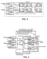
- FIG. 2 A situation where a power supply failure arises due, for instance, to shorting to ground on the motherboard will now be described with reference to a block diagram shown in FIG. 2.
- the first total line output is lost as DC power supply line A is shorted to ground on the motherboard
- the second total line output is supplied along DC power supply line B to make up for the loss. More specifically, if the shorted DC power supply line A is connected to the upper diode having a low on-resistance, when the first total line output is lost, the HDD 210, to which the first total line output had been supplied, will automatically switch to the second total line output supply scheme via DC power supply line B, which is connected to the lower diode having a high on-resistance. This ensures that the HDD 210 and other components can be accessed normally even in the event of shorting to ground on the motherboard.
- the HDD interface control circuits 500A and 500B which are loads provided on the motherboard, form a redundant circuit and receive operating power from a total line output via a DC-DC converter. Therefore, if, for example, any failure occurs in a HDD interface control circuit 500A, the DC-DC converter prevents the other components from being affected by the failure. Consequently, the remaining HDD interface control circuit 500B can continue to operate normally. As a result, since the HDDs 210 mounted to the motherboard remain accessible, no problem will arise in the disk array device.
- the time required for data recovery subsequent to failure recovery will be about the same as the time required for recovering one HDD 210. This eliminates the need for using high-reliability parts that endure the period of data recovery for all the mounted HDDs 210.
- power supply noise is generated by all of the n units of HDDs 210 along a long power supply path between the AC/DC power supplies 300a, 300b and the HDDs 210.
- the power supply noise is generated by a plurality of HDDs that share the same power supply. This power supply noise is generated due, for instance, to a ripple current caused by the operating state differences (for example, the difference in access states such as idle, seek, and read/write) among the HDDs, or a voltage drop caused by an impedance that the power supply path has.
- a DC-DC converter is provided as a power supply for the loads such as the HDD 210, and the DC-DC converter is connected to the power input terminal of the loads as shown in the block diagram of FIG. 4. Therefore, voltage drop and power supply noise generation occur only in the power supply paths within individual HDD housings 200. More specifically, voltage drop and power supply noise generation occur within a short power supply path between the constant voltage circuit section 220a and the HDD 210. As a result, the degree of voltage drop and power supply noise generation can be considerably reduced. Further, the DC-DC converter 220 can follow up on load variations so as to minimize the input voltage change resulting from the load variations.
- the output voltages of the AC/DC power supplies 300a, 300b are set at a value greater than the output voltage of the DC-DC converter 220. In this way, the current flow and voltage drop in a power supply path between the AC/DC power supplies 300a, 300b and the DC-DC converter can be reduced as shown in FIG. 4. Therefore, not only can the amount of noise generation from the power feed path be reduced, but low-power-consumption, small-size, inexpensive parts can be used for the power feed path.
- a control line for power supply instruction is connected from the power supply control logic section 600 to the DC-DC converter 220 to make the DC-DC converter 220 operate. In this way, the DC-DC converter 220 will not operate until a HDD housing 200 is properly mounted to the motherboard and the converter 220 receives a power supply instruction signal (POWER ON signal).
- POWER ON signal a power supply instruction signal
- the DC-DC converter 220 When the DC-DC converter 220 starts operating and oscillating, the output voltage linearly builds up. As a result, it looks as if the inrush current to a HDD 210 is inhibited. It can therefore be said that the DC-DC converter 220 has an inrush current protection function. Further, since only the input current limited by the DC-DC converter 220 flows from the AC/DC power supplies 300a, 300b to the DC-DC converter 220, it becomes possible to supply stabilized voltage to the other loads to which the same total line output is supplied, and it is not necessary to furnish a dedicated circuit for inrush current protection.
- the anode on the upper backflow prevention diode having a low on-resistance is connected to DC power supply line A so that the first total line output can be supplied to the anode
- the anode on the lower backflow prevention diode having a high on-resistance is connected to DC power supply line B so that the second total line output can be supplied to the anode.
- the anode on the upper backflow prevention diode having a low on-resistance is connected to DC power supply line B so that the second total line output can be supplied to the anode
- the anode on the lower backflow prevention diode having a high on-resistance is connected to DC power supply line A so that the first total line output can be supplied to the anode.
- the number of DC-DC converters 220 provided with the backflow prevention diode having a low on-resistance connected to the first total line output is equal to the number of DC-DC converters 220 provided with the backflow prevention diode having a low on-resistance connected to the second total line output.
- the expression, "the numbers of DC-DC converters 220 are equal,” has the following meaning: when an even number of HDDs 210 exist within the housing, the number can be divided by two, which is the number of groups (lines), and the number is the same; and, when an odd number of HDDs 210 exist within the housing, the difference in the number is 1.
- the numbers of DC-DC converters 220 are exactly equal or substantially equal as far as the first total line output and the second total line output supplied to the DC-DC converters 220 are equally distributed.
- the expression, “equally distributed,” can also mean that the AC input to be the source for the first total line output and the AC input to be the source for the second total line output are equally distributed in terms of electricity.
- the configuration of connecting the DC power supply lines A and B to the upper and lower backflow prevention diodes to ensure that the first and second total line outputs supplied to the DC-DC converters 220 are equally distributed is not limited to that of the present embodiment; various other designs can also be adopted.
- a controller 700 comprises a host interface control section 710, a memory 720, and a HDD interface control section 730. According to a state in which data is being written into the HDDs 210, the controller 700 sends, to the power supply control logic section 600 via the HDD interface control section 730, a signal for controlling the operation of each of the DC-DC converters 220. In accordance with the received signal, the power supply control logic section 600 transmits an ON or OFF control signal to the constant voltage circuit sections 220a of each of the DC-DC converters 220.
- the output operations of the DC-DC converters 220 are individually controlled so as to exercise power feed control over the HDDs 210 on an individual basis.
- stable output voltage supply can be provided by the DC-DC converters that are furnished individually for each HDD 210. Therefore, when each load, such as the HDD 210, does not have to be operated, the output of a DC-DC converter 220 can be shut off as appropriate with a control signal.
- the battery section 400 which acts as an auxiliary power supply
- the present invention makes it possible to individually shut off the power supply output to loads that need not operate.
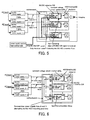
- a power monitoring section 210b of each HDD 210 monitors the power supply status and reports it to the controller (disk control section ) 700 as described earlier and as shown in FIG. 8.
- the controller 700 saves data or takes some other failure recovery action. Therefore, even if a DC-DC converter failure occurs, only the associated HDD will fail and all the other components remain intact. It is therefore possible to save data on a spare disk.
- the disk control section 700 If the data for the failed HDD 210 has already been written into the memory 720 of the disk control section 700 when the disk control section 70 receives a power supply failure report from the power monitoring section 210b of the HDD 210, the disk control section 700 reads the data from the memory 720 and writes it on a spare disk in some other normal HDD 210 ((5) in FIG. 8). The disk control section 700 then operates using the spare disk in the normal HDD 210 until the power supply failure is recovered. The other normal HDD 210 that has not failed informs the disk control section 700 that it is operating normally ((4) in FIG. 8).
- the disk control section 700 upon receipt of a power supply failure report from the power monitoring section 210b of the HDD 210, the disk control section 700 sends a request to a host device to halt data transfer and to change the destination of data read/data write process from disk array device 1 to disk array device 2 (disk subsystem 2 in the figure) ((3) in FIG. 9).
- the disk control section 700 in disk array device 1 confirms that disk array device 2 is operating normally ((4) in FIG. 9). After confirmation, the disk control section 700 in disk array device 1 copies the necessary data in disk array device 1 to disk array device 2, which is operating normally ((5) in FIG. 9).
- the host device then changes the destination of the data read/data write process from disk array device 1 to disk array device 2 ((6) in FIG. 9).
- the block diagram in FIG. 10 shows a case where the present invention is used for disk array device virtualization.
- a plurality of HDDs 210 including HDDs 210 at a remote site, are managed and operated as a single disk.
- the disk control section 700 If the data for the failed HDD 210 has already been written into the memory 720 of the disk control section 700 when the disk control section 70 receives a power supply failure report from the power monitoring section 210b of the HDD 210, the disk control section 700 reads the data from the memory 720 and writes it on a spare disk in some other normal HDD 210 ((5) in FIG. 10). The disk control section 700 then operates using the normal HDD 210 until the power supply failure is recovered. The other normal HDDs 210 (including those at remote sites) that have not failed inform the disk control section 700 that they are operating normally ((4) in FIG. 10).
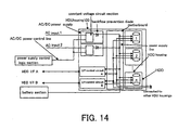
- a modified version of the present embodiment will now be described with reference to FIG. 11.
- the modified version does not have the battery section 400
- the present invention can be implemented because a duplex AC input is provided in a redundant manner as a power supply system. Either one of the two AC inputs performs the auxiliary power supply function of the battery section 400.
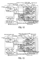
- FIG. 12 shows a modified version of the embodiment shown in FIG. 12.
- the total output of the AC/DC power supplies 300a is delivered to both the battery section 400 and power supply control logic section 600.
- a switching device is provided in DC power supply line B, which is connected to the battery section 400.
- This switching device includes a power MOS FET and is subjected to ON/OFF control by the power supply control logic section 600.
- the power supply control logic section 600 monitors the total output status; the logic section 600 makes the switching device turn ON only when the output of the battery section 400 is required, and otherwise, the switching device is kept OFF.
- a plurality of total line outputs are used as operating power for each load within a disk array device. Therefore, even if a certain total line output is lost due, for instance, to a failure, another total output is supplied, as operating power, to all loads within a disk array device. The disk array device operation is therefore kept normal.
- the fault can be confined within a single failed HDD. Therefore, the time required for data recovery subsequent to failure recovery is no more than the time required for the recovery of one HDD. This eliminates the need for using high-reliability parts that endure the period of data recovery for all the mounted HDDs.
- the HDD interface control circuitry which is a load mounted on the motherboard, is duplexed and receives operating power from total line outputs via DC-DC converters. Therefore, even if a failure occurs in one HDD interface control circuit, the DC-DC converter prevents the failure from spreading, thereby ensuring the normal operation of the remaining HDD interface control circuit. As a result, no problem arises in accessing the HDDs mounted on the motherboard; therefore, there is no problem in the disk array device as a whole.
- a circuit board on which HDDs, HDD interface control circuits, and other components are mounted as loads to which operating power should be supplied, has a DC-DC converter, which is to be connected to the power input terminals of these loads. It is therefore possible to minimize the wiring distance between the power input terminals and DC-DC converter, thereby considerably reducing voltage drop and noise generation.
- the DC-DC converter can also follow up on load variation for each load, thereby minimizing the input voltage variation arising out of such load variation.
- the control line for instructing power supply is connected to the DC-DC converter to make the DC-DC converter operative only after the HDD housing is properly mounted to the motherboard. Therefore, the DC-DC converter does not operate until the HDD housing properly is mounted to the motherboard and a power supply instruction signal is received.
- the DC-DC converter When the DC-DC converter starts operating and oscillating, the output voltage linearly builds up. As a result, it looks as if the inrush current to a HDD is inhibited. It can therefore be said that the DC-DC converter has an inrush current protection function. Further, since only the input current limited by the DC-DC converter flows from the AC/DC power supplies to the DC-DC converter, it becomes possible to supply stabilized voltage to the other loads to which the same total line output is supplied, and it is not necessary to furnish a dedicated circuit for inrush current protection.
- the output voltages of the AC/DC power supplies are set at a value greater than the regulated DC power supply's output voltage. In this way, the current flow and voltage drop in a power feed path between the AC/DC power supplies and DC-DC converter can be reduced. Therefore, not only can the amount of noise generation from the power feed path be reduced, but low-power-consumption, small-size, inexpensive parts can be used for the power feed path.
- the first and second total line outputs are used as the inputs for the regulated DC power supplies.
- the first and second total line outputs are normal, the total line output connected to the backflow prevention diode having a low on-resistance is used as the regulated DC power supply's input.
- the system is configured so that a number of DC stabilized power supplies provided with the backflow prevention diode having a low on-resistance connected to the first total line output and a number of DC stabilized power supplies provided with the backflow prevention diode having a low on-resistance connected to the second total line output are substantially the same. This ensures that the first and second total line outputs to be supplied to all regulated DC power supplies are equally distributed.
- the input current for the AC/DC power supplies is about half (1/2) the total current consumption during a normal operation.
- the amount of high-frequency noise generation from the AC/DC power supplies can be decreased.
- the output operations of the regulated DC power supplies provided for various loads, such as the HDDs, are individually controlled. More specifically, power feed control can be exercised individually for all HDDs, and stable output voltage supply can be provided by the regulated DC power supplies that are furnished individually for the HDDs. Therefore, when a load, such as a HDD, does not have to be operated, the output of a regulated DC power supply can be shut off as appropriate with a control signal.
- the present invention makes it possible to individually shut off the power supply output to loads that need not operate.
- the size, weight, and price of the disk array device can be reduced.
- each regulated DC power supply that is provided for outputting a supply voltage to the disk drive(s) for which the write process has been finished is stopped. This reduces the battery section's power consumption for the destaging process.
- the present invention can enhance the reliability of disk array devices.
Landscapes
- Engineering & Computer Science (AREA)
- Theoretical Computer Science (AREA)
- Physics & Mathematics (AREA)
- General Engineering & Computer Science (AREA)
- General Physics & Mathematics (AREA)
- Power Sources (AREA)
- Direct Current Feeding And Distribution (AREA)
- Stand-By Power Supply Arrangements (AREA)
Abstract
Description
Claims (11)
- A disk array device to which power is supplied by at least two AC inputs, comprising:at least two AC/DC power-supply groups provided in correspondence with each of said AC inputs, each said AC/DC power-supply group including at least two AC/DC power supplies that are connected to the AC input corresponding to that group, whereinoutputs from said AC/DC power supplies are summed separately for each group as group total outputs, andsaid group total outputs are input to each of a plurality of loads in said disk array device to provide power to each said loads.
- A disk array device to which power is supplied by an AC input, comprising:wherein said total output and an output of said battery section are input to each of a plurality of loads in said disk array device to provide power to each said loads.at least two AC/DC power supplies that are connected to said AC input, wherein outputs of each of said AC/DC power supplies are connected to provide a total output; anda battery section to which said total output is provided as an input thereof,
- A method of supplying power to a disk array device to which power is supplied by at least two AC inputs, said method comprising:where at least two AC/DC power-supply groups are provided in correspondence with each of said AC inputs and each said AC/DC power-supply group includes at least two AC/DC power supplies that are connected to the AC input corresponding to that group,summing outputs from said AC/DC power supplies separately for each group to obtain group total outputs for each group; andinputting said group total outputs to each of a plurality of loads in said disk array device to provide power to each said loads.
- A method of supplying power to a disk array device to which power is supplied by an AC input, said method comprising:where at least two AC/DC power supplies are connected to said AC input, outputs of each of said AC/DC power supplies are connected to provide a total output, and said total output is provided to a battery section as an input thereof,inputting said total output and an output of said battery section to each of a plurality of loads in said disk array device to provide power to each said loads.
- The device of claim 1 or the method of claim 3, wherein each of said loads is provided with a regulated DC power supply for generating a supply voltage from said group total outputs.
- The device or method of claim 5, wherein said regulated DC power supply is a DC-DC converter.
- The device or method of claim 5, wherein said load is a disk drive, and a housing containing said disk drive includes said regulated DC power supply.
- The device or method of claim 5, wherein an output voltage of said AC/DC power supply is higher than an output voltage of said regulated DC power supply.
- The device or method of claim 5, wherein each of said group total outputs is made of a first group total output and a second group total output,
each said DC stabilised power supply of each of said loads has a first backflow prevention device having a first turn-on voltage and a second backflow prevention device having a second turn-on voltage that is higher than said first turn-on voltage,
one end of said first backflow prevention device and one end of said second backflow prevention device in each said DC stabilised power supply are connected to each other, and a number of DC stabilised power supplies in which another end of said first backflow prevention device is connected to said first group total output and
a number of DC stabilised power supplies in which another end of said first backflow prevention device is connected to said second group total output are substantially the same. - The device or method of claim 5, wherein said regulated DC power supply outputs said supply voltage to said loads in accordance with a control signal that is input to said regulated DC power supply.
- The device or method of claim 7, wherein, when a write process is performed to write data stored in a memory onto said disk drive in response to a write instruction received from an external host device, a power supply control circuit outputs a control signal to stop the operation of the regulated DC power supply that is provided for outputting said supply voltage to said disk drive for which said write process has been finished.
Applications Claiming Priority (2)
| Application Number | Priority Date | Filing Date | Title |
|---|---|---|---|
| JP2002290739A JP4230189B2 (en) | 2002-10-03 | 2002-10-03 | Disk array device and power supply method thereof |
| JP2002290739 | 2002-10-03 |
Publications (2)
| Publication Number | Publication Date |
|---|---|
| EP1411523A2 true EP1411523A2 (en) | 2004-04-21 |
| EP1411523A3 EP1411523A3 (en) | 2006-03-29 |
Family
ID=32040667
Family Applications (1)
| Application Number | Title | Priority Date | Filing Date |
|---|---|---|---|
| EP03013044A Ceased EP1411523A3 (en) | 2002-10-03 | 2003-06-10 | Disk array device and method of supplying power thereto |
Country Status (4)
| Country | Link |
|---|---|
| US (4) | US7051216B2 (en) |
| EP (1) | EP1411523A3 (en) |
| JP (1) | JP4230189B2 (en) |
| CN (1) | CN1246750C (en) |
Cited By (9)
| Publication number | Priority date | Publication date | Assignee | Title |
|---|---|---|---|---|
| GB2411057A (en) * | 2004-02-11 | 2005-08-17 | Hewlett Packard Development Co | Power distribution system having plurality of power sources |
| GB2411056A (en) * | 2004-02-11 | 2005-08-17 | Hewlett Packard Development Co | Power distribution system having redundant sources |
| EP1830271A1 (en) * | 2006-03-01 | 2007-09-05 | Hitachi, Ltd. | Power supply device and power supply method |
| EP1843248A1 (en) * | 2006-04-07 | 2007-10-10 | Hitachi, Ltd. | Driving method of storage apparatus and disk subsystem including such storage apparatus |
| WO2008125039A1 (en) | 2007-04-13 | 2008-10-23 | Huawei Technologies Co., Ltd. | Magnetic disk array device |
| WO2010097840A1 (en) * | 2009-02-27 | 2010-09-02 | Hitachi, Ltd. | Redundant power supply apparatus |
| WO2011092743A1 (en) * | 2010-01-29 | 2011-08-04 | Hitachi, Ltd. | Storage system |
| WO2013024512A1 (en) * | 2011-08-18 | 2013-02-21 | Hitachi, Ltd. | Storage apparatus with redundant power supply |
| WO2013114420A1 (en) * | 2012-01-30 | 2013-08-08 | Hitachi, Ltd. | Storage apparatus |
Families Citing this family (59)
| Publication number | Priority date | Publication date | Assignee | Title |
|---|---|---|---|---|
| JP4325817B2 (en) * | 1999-04-05 | 2009-09-02 | 株式会社日立製作所 | Disk array device |
| JP4230189B2 (en) | 2002-10-03 | 2009-02-25 | 株式会社日立製作所 | Disk array device and power supply method thereof |
| JP4025216B2 (en) | 2003-02-21 | 2007-12-19 | 株式会社日立製作所 | Uninterruptible power system |
| US7424627B2 (en) * | 2003-05-22 | 2008-09-09 | Canon Kabushiki Kaisha | Storage device protection system, method for protecting hard disk thereof, medium for providing control program, and control program |
| US8301809B2 (en) * | 2003-07-02 | 2012-10-30 | Infortrend Technology, Inc. | Storage virtualization computer system and external controller thereof |
| JP4391192B2 (en) | 2003-10-09 | 2009-12-24 | 株式会社日立製作所 | Disk array device |
| JP2005115771A (en) * | 2003-10-09 | 2005-04-28 | Hitachi Ltd | Disk array device |
| JP4486348B2 (en) * | 2003-11-26 | 2010-06-23 | 株式会社日立製作所 | Disk array that suppresses drive operating time |
| JP4642347B2 (en) * | 2003-12-10 | 2011-03-02 | 株式会社日立製作所 | Storage system |
| JP4497918B2 (en) * | 2003-12-25 | 2010-07-07 | 株式会社日立製作所 | Storage system |
| JP4518541B2 (en) * | 2004-01-16 | 2010-08-04 | 株式会社日立製作所 | Disk array device and disk array device control method |
| JP4634049B2 (en) | 2004-02-04 | 2011-02-16 | 株式会社日立製作所 | Error notification control in disk array system |
| US7363525B2 (en) * | 2004-10-07 | 2008-04-22 | Cisco Technology, Inc. | Bidirectional inline power port |
| JP2005346321A (en) * | 2004-06-02 | 2005-12-15 | Hitachi Ltd | Disk array device and battery output control method for disk array device |
| US8051260B1 (en) * | 2004-06-30 | 2011-11-01 | Emc Corporation | Determining environmental availability in a storage subsystem |
| JP4605637B2 (en) * | 2004-07-29 | 2011-01-05 | 株式会社日立製作所 | Storage device system and signal transmission method in storage device system |
| US9495263B2 (en) * | 2004-12-21 | 2016-11-15 | Infortrend Technology, Inc. | Redundant SAS storage virtualization subsystem and system using the same, and method therefor |
| US8301810B2 (en) * | 2004-12-21 | 2012-10-30 | Infortrend Technology, Inc. | SAS storage virtualization controller, subsystem and system using the same, and method therefor |
| CN101107581B (en) * | 2005-01-25 | 2010-08-18 | 松下电器产业株式会社 | Power Systems |
| JP4585325B2 (en) * | 2005-02-08 | 2010-11-24 | 株式会社日立製作所 | Disk array device |
| US7475806B1 (en) * | 2005-02-24 | 2009-01-13 | Savr Communications, Inc. | Method and system of universal RFID communication |
| JP2006313487A (en) | 2005-05-09 | 2006-11-16 | Hitachi Ltd | Disk array device |
| JP4769805B2 (en) * | 2005-07-29 | 2011-09-07 | 株式会社サイバー・ソリューションズ | Network management system and network management information collection method |
| JP2007188421A (en) * | 2006-01-16 | 2007-07-26 | Fujitsu Ltd | Power supply control device and power supply control method |
| CN100483893C (en) * | 2006-01-20 | 2009-04-29 | 新巨企业股份有限公司 | Redundant Power Supply System |
| JP4800059B2 (en) * | 2006-02-13 | 2011-10-26 | 株式会社日立製作所 | Virtual storage system and control method thereof |
| JP2007233793A (en) * | 2006-03-02 | 2007-09-13 | Nec Corp | Disk enclosure device |
| JP4749308B2 (en) | 2006-10-20 | 2011-08-17 | 株式会社日立製作所 | Power supply device and power supply method for power supply device |
| JP5109333B2 (en) * | 2006-10-26 | 2012-12-26 | サンケン電気株式会社 | Power supply |
| JP4804377B2 (en) * | 2007-02-08 | 2011-11-02 | 株式会社日立製作所 | Power supply device and storage control device |
| US20080309160A1 (en) * | 2007-06-14 | 2008-12-18 | Hewlett-Packard Development Company, L. P. | Modular blade enclosure power subsystem disign |
| JP4833164B2 (en) * | 2007-07-24 | 2011-12-07 | 株式会社日立製作所 | Storage subsystem and power supply system |
| US7877622B2 (en) * | 2007-12-13 | 2011-01-25 | International Business Machines Corporation | Selecting between high availability redundant power supply modes for powering a computer system |
| US20100141039A1 (en) * | 2009-01-19 | 2010-06-10 | Microsoft Corporation | High availability, high efficiency data center electrical distribution |
| US8504860B2 (en) * | 2009-06-26 | 2013-08-06 | Seagate Technology Llc | Systems, methods and devices for configurable power control with storage devices |
| KR101255686B1 (en) * | 2009-07-23 | 2013-04-17 | 한국전자통신연구원 | structure of rackmount computer |
| US8723362B2 (en) * | 2009-07-24 | 2014-05-13 | Facebook, Inc. | Direct tie-in of a backup power source to motherboards in a server system |
| US8067857B2 (en) * | 2009-07-29 | 2011-11-29 | Hewlett-Packard Development Company, L.P. | Redundant power supply systems and methods |
| US20110185099A1 (en) * | 2010-01-28 | 2011-07-28 | Lsi Corporation | Modular and Redundant Data-Storage Controller And a Method for Providing a Hot-Swappable and Field-Serviceable Data-Storage Controller |
| WO2011158294A1 (en) * | 2010-06-17 | 2011-12-22 | Hitachi, Ltd. | Storage apparatus and method of detecting power failure in storage apparatus |
| US20120042175A1 (en) * | 2010-08-12 | 2012-02-16 | Hou-Yuan Lin | Motherboard with an energy saving function |
| JP2012100375A (en) * | 2010-10-29 | 2012-05-24 | Hitachi Ltd | Parallel power supply system |
| TW201325026A (en) * | 2011-12-15 | 2013-06-16 | Hon Hai Prec Ind Co Ltd | Uninterruptible power supply system |
| US8751836B1 (en) * | 2011-12-28 | 2014-06-10 | Datadirect Networks, Inc. | Data storage system and method for monitoring and controlling the power budget in a drive enclosure housing data storage devices |
| EP2624412A1 (en) * | 2012-02-06 | 2013-08-07 | Siemens Aktiengesellschaft | Power supply |
| JP5962101B2 (en) * | 2012-03-19 | 2016-08-03 | 富士通株式会社 | Backup power supply device, power supply system, computer system, power control method for computer system, and power control program |
| CN103514078A (en) * | 2012-06-28 | 2014-01-15 | 鸿富锦精密工业(深圳)有限公司 | Hard disk monitoring system |
| CN103513740A (en) * | 2012-06-28 | 2014-01-15 | 鸿富锦精密工业(深圳)有限公司 | Hard disk power supply circuit and hard disk back plate |
| TW201401720A (en) * | 2012-06-29 | 2014-01-01 | Hon Hai Prec Ind Co Ltd | Uninterruptible power supply system |
| CN205326821U (en) * | 2013-07-02 | 2016-06-22 | 三菱电机株式会社 | combined drive system |
| US9939865B2 (en) | 2014-06-13 | 2018-04-10 | Seagate Technology Llc | Selective storage resource powering for data transfer management |
| US10534417B1 (en) | 2015-03-10 | 2020-01-14 | Amazon Technologies, Inc. | Mass storage device electrical power consumption monitoring |
| CN104914972A (en) * | 2015-06-03 | 2015-09-16 | 浪潮集团有限公司 | DDR3 power supply device and method |
| CN106300325A (en) * | 2016-09-27 | 2017-01-04 | 天津大学 | A DC power supply system for data centers |
| EP3518369A1 (en) | 2018-01-30 | 2019-07-31 | Siemens Aktiengesellschaft | Method and control device for regulating electric power transfer and power network |
| CN110413218B (en) * | 2018-04-28 | 2023-06-23 | 伊姆西Ip控股有限责任公司 | Method, apparatus and computer program product for fault recovery in a storage system |
| CN109656752B (en) * | 2019-01-17 | 2023-04-18 | 浙江建设职业技术学院 | Data backup storage device for smart campus management system and installation method thereof |
| US12289011B2 (en) | 2022-02-16 | 2025-04-29 | Equinix, Inc. | Aggregating unused power in a facility |
| US12489299B2 (en) * | 2023-10-10 | 2025-12-02 | Lenovo Enterprise Solutions (Singapore) Pte. Ltd. | Configurable current steering in a printed circuit board |
Family Cites Families (53)
| Publication number | Priority date | Publication date | Assignee | Title |
|---|---|---|---|---|
| JPS57164318A (en) | 1981-04-02 | 1982-10-08 | Toshiba Corp | Information processing system |
| US5673412A (en) | 1990-07-13 | 1997-09-30 | Hitachi, Ltd. | Disk system and power-on sequence for the same |
| US5325363A (en) | 1992-05-11 | 1994-06-28 | Tandem Computers Incorporated | Fault tolerant power supply for an array of storage devices |
| US5675816A (en) | 1992-05-26 | 1997-10-07 | Fujitsu Limited | Magnetic disk subsystem with failsafe battery charging and power shut down |
| WO1993024878A1 (en) | 1992-05-26 | 1993-12-09 | Fujitsu Limited | Magnetic disk device |
| US6029199A (en) | 1992-10-23 | 2000-02-22 | International Business Machines Corporation | Computing system having a system supervisor and a collection of computing subunits each of which has a subunit supervisor |
| US5471099A (en) * | 1992-11-16 | 1995-11-28 | Hjs&E Engineering | Modular enclosure apparatus |
| JPH0793045A (en) | 1993-09-28 | 1995-04-07 | Fujitsu Ltd | Computer input / output device |
| JP2833460B2 (en) | 1993-12-27 | 1998-12-09 | 株式会社日立製作所 | Power system |
| US5832281A (en) | 1994-10-19 | 1998-11-03 | Canon Kabushiki Kaisha | Power control apparatus and power control method |
| JP3474665B2 (en) | 1995-03-02 | 2003-12-08 | 富士通株式会社 | Power supply control apparatus and method for computer system |
| US5842030A (en) | 1995-10-04 | 1998-11-24 | Larabell; Henri | Memory storage system having swappable power supplies |
| KR100310100B1 (en) | 1996-07-10 | 2001-12-17 | 윤종용 | Power supply apparatus for portable computer and dc input selection circuit adapted to same |
| US5790374A (en) | 1996-12-06 | 1998-08-04 | Ncr Corporation | Method and apparatus for providing power activity and fault light support using light conduits for single connector architecture (SCA) disk drives |
| US6742068B2 (en) | 1997-06-30 | 2004-05-25 | Emc Corporation | Data server with hot replaceable processing unit modules |
| JP3618529B2 (en) | 1997-11-04 | 2005-02-09 | 富士通株式会社 | Disk array device |
| US6272573B1 (en) | 1997-12-24 | 2001-08-07 | International Business Machines Corporation | Scalable modular data storage system |
| JP4083864B2 (en) | 1998-04-20 | 2008-04-30 | 株式会社日立製作所 | Interlocking control device between host, disk array and UPS |
| US6014319A (en) * | 1998-05-21 | 2000-01-11 | International Business Machines Corporation | Multi-part concurrently maintainable electronic circuit card assembly |
| FI107418B (en) * | 1998-05-22 | 2001-07-31 | Muuntolaite Oy | Method and plant for controlling a power source system |
| US6622164B1 (en) * | 1998-09-11 | 2003-09-16 | Quantum Corp. | Mass storage device with network interface |
| DE69910172T2 (en) * | 1998-09-25 | 2004-05-19 | Koninklijke Philips Electronics N.V. | CIRCUIT WITH PSEUDO MULTI-PORT MEMORY |
| US6311279B1 (en) | 1998-10-27 | 2001-10-30 | Compaq Computer Corporation | Network node with internal battery backup |
| JP2000197347A (en) | 1998-12-25 | 2000-07-14 | Hitachi Ltd | Power supply |
| KR100561379B1 (en) | 1999-01-08 | 2006-03-16 | 삼성전자주식회사 | Docking system safe from docking system power supply |
| US6317839B1 (en) | 1999-01-19 | 2001-11-13 | International Business Machines Corporation | Method of and apparatus for controlling supply of power to a peripheral device in a computer system |
| US6694438B1 (en) | 1999-07-02 | 2004-02-17 | Advanced Energy Industries, Inc. | System for controlling the delivery of power to DC computer components |
| JP4325817B2 (en) * | 1999-04-05 | 2009-09-02 | 株式会社日立製作所 | Disk array device |
| US6341354B1 (en) | 1999-04-16 | 2002-01-22 | Smartpower Corporation | Energy-conserving computer accessible remotely and instantaneously by providing keep-alive power to memory |
| US6231224B1 (en) | 1999-09-22 | 2001-05-15 | International Business Machines Corporation | Light pipe guide and carrier for hard disk drive |
| JP4071419B2 (en) | 2000-05-25 | 2008-04-02 | 株式会社日立製作所 | Disk array device |
| US20020165894A1 (en) | 2000-07-28 | 2002-11-07 | Mehdi Kashani | Information processing apparatus and method |
| US6510050B1 (en) | 2000-11-21 | 2003-01-21 | Sun Microsystems, Inc. | High density packaging for multi-disk systems |
| US6833634B1 (en) * | 2001-01-04 | 2004-12-21 | 3Pardata, Inc. | Disk enclosure with multiple power domains |
| TW579503B (en) | 2001-08-24 | 2004-03-11 | Icp Electronics Inc | Disk array control apparatus |
| JP3686863B2 (en) | 2001-11-30 | 2005-08-24 | Necアクセステクニカ株式会社 | Uninterruptible power system |
| US20030177404A1 (en) | 2002-03-14 | 2003-09-18 | Jorgenson Joel A. | Power distribution control system and method for limiting transient current conditions in computer architectures |
| JP3785377B2 (en) | 2002-03-29 | 2006-06-14 | インターナショナル・ビジネス・マシーンズ・コーポレーション | Electric device, computer apparatus, intelligent battery, and AC adapter confirmation method |
| JP3673239B2 (en) | 2002-04-22 | 2005-07-20 | 株式会社東芝 | Computer equipment |
| JP4219610B2 (en) * | 2002-04-23 | 2009-02-04 | 株式会社日立製作所 | Disk subsystem device |
| EP1361516A3 (en) | 2002-04-30 | 2011-05-18 | Hitachi, Ltd. | Method and system for backing up power supply of disk array device |
| JP4216006B2 (en) | 2002-06-14 | 2009-01-28 | 株式会社日立製作所 | Storage device control method |
| JP2004038290A (en) | 2002-06-28 | 2004-02-05 | Toshiba Corp | Disk control method used in an information processing system and the system |
| JP2004038331A (en) | 2002-06-28 | 2004-02-05 | Toshiba Corp | Information processing apparatus and method for supplying power to the information processing apparatus |
| JP4230189B2 (en) | 2002-10-03 | 2009-02-25 | 株式会社日立製作所 | Disk array device and power supply method thereof |
| US7131011B2 (en) | 2002-10-30 | 2006-10-31 | Microsoft Corporation | System and method for preserving state data of a personal computer in a standby state in the event of an AC power failure |
| JP4352693B2 (en) | 2002-12-10 | 2009-10-28 | 株式会社日立製作所 | Disk array control device and control method thereof |
| JP4372427B2 (en) | 2003-01-20 | 2009-11-25 | 株式会社日立製作所 | Storage device controller |
| JP4038134B2 (en) | 2003-02-05 | 2008-01-23 | インターナショナル・ビジネス・マシーンズ・コーポレーション | Power supply control apparatus and information processing apparatus |
| US7516272B2 (en) | 2003-03-28 | 2009-04-07 | Emc Corporation | Midplane-independent implementations of data storage system enclosures |
| US6954712B2 (en) | 2003-04-01 | 2005-10-11 | International Business Machines Corporation | Multi-mode SCSI diagnostic tool, system, and method |
| TWI280475B (en) | 2003-06-16 | 2007-05-01 | Wistron Corp | Method of controlling operation mode of a computer system |
| JP2005115771A (en) | 2003-10-09 | 2005-04-28 | Hitachi Ltd | Disk array device |
-
2002
- 2002-10-03 JP JP2002290739A patent/JP4230189B2/en not_active Expired - Fee Related
-
2003
- 2003-06-10 EP EP03013044A patent/EP1411523A3/en not_active Ceased
- 2003-06-16 US US10/463,723 patent/US7051216B2/en not_active Expired - Fee Related
- 2003-07-07 CN CN03147172.2A patent/CN1246750C/en not_active Expired - Fee Related
-
2005
- 2005-05-25 US US11/137,985 patent/US7131014B2/en not_active Expired - Fee Related
-
2006
- 2006-09-20 US US11/523,547 patent/US7284140B2/en not_active Expired - Fee Related
-
2007
- 2007-07-03 US US11/822,182 patent/US7681061B2/en not_active Expired - Fee Related
Cited By (15)
| Publication number | Priority date | Publication date | Assignee | Title |
|---|---|---|---|---|
| GB2411057A (en) * | 2004-02-11 | 2005-08-17 | Hewlett Packard Development Co | Power distribution system having plurality of power sources |
| GB2411056A (en) * | 2004-02-11 | 2005-08-17 | Hewlett Packard Development Co | Power distribution system having redundant sources |
| EP1830271A1 (en) * | 2006-03-01 | 2007-09-05 | Hitachi, Ltd. | Power supply device and power supply method |
| US7557461B2 (en) | 2006-03-01 | 2009-07-07 | Hitachi, Ltd. | Power supply device and power supply method |
| EP1843248A1 (en) * | 2006-04-07 | 2007-10-10 | Hitachi, Ltd. | Driving method of storage apparatus and disk subsystem including such storage apparatus |
| US7698595B2 (en) | 2006-04-07 | 2010-04-13 | Hitachi, Ltd. | Driving method of storage apparatus and disk subsystem including such storage apparatus |
| EP2065892A4 (en) * | 2007-04-13 | 2009-08-19 | Huawei Tech Co Ltd | MAGNETIC DISC DISK DEVICE |
| WO2008125039A1 (en) | 2007-04-13 | 2008-10-23 | Huawei Technologies Co., Ltd. | Magnetic disk array device |
| WO2010097840A1 (en) * | 2009-02-27 | 2010-09-02 | Hitachi, Ltd. | Redundant power supply apparatus |
| US8135967B2 (en) | 2009-02-27 | 2012-03-13 | Hitachi, Ltd. | Storage system |
| US8572415B2 (en) | 2009-02-27 | 2013-10-29 | Hitachi, Ltd. | Storage system |
| WO2011092743A1 (en) * | 2010-01-29 | 2011-08-04 | Hitachi, Ltd. | Storage system |
| US8380997B2 (en) | 2010-01-29 | 2013-02-19 | Hitachi, Ltd. | Power supply of storage system |
| WO2013024512A1 (en) * | 2011-08-18 | 2013-02-21 | Hitachi, Ltd. | Storage apparatus with redundant power supply |
| WO2013114420A1 (en) * | 2012-01-30 | 2013-08-08 | Hitachi, Ltd. | Storage apparatus |
Also Published As
| Publication number | Publication date |
|---|---|
| CN1487389A (en) | 2004-04-07 |
| JP4230189B2 (en) | 2009-02-25 |
| EP1411523A3 (en) | 2006-03-29 |
| US7131014B2 (en) | 2006-10-31 |
| US20070016811A1 (en) | 2007-01-18 |
| JP2004126972A (en) | 2004-04-22 |
| CN1246750C (en) | 2006-03-22 |
| US7051216B2 (en) | 2006-05-23 |
| US7681061B2 (en) | 2010-03-16 |
| US20040068670A1 (en) | 2004-04-08 |
| US7284140B2 (en) | 2007-10-16 |
| US20050216777A1 (en) | 2005-09-29 |
| US20070255968A1 (en) | 2007-11-01 |
Similar Documents
| Publication | Publication Date | Title |
|---|---|---|
| US7051216B2 (en) | Disk array device and method of supplying power to disk array device | |
| KR102889920B1 (en) | Cost-effective solid state disk data-protection method for power outages | |
| US7671485B2 (en) | Storage system | |
| US10922260B2 (en) | Modular carrier form factors for computing platforms | |
| JP4804377B2 (en) | Power supply device and storage control device | |
| US7051233B2 (en) | Method for backing up power supply of disk array device and system thereof | |
| US7222246B2 (en) | Method for determining number of dynamically temperature-adjusted power supply units needed to supply power according to measure operating temperature of power supply units | |
| US7272733B2 (en) | Method of providing dynamic power redundancy based on a difference of current power units and currently needed power units | |
| US11404906B1 (en) | Power failure protection system for solid state drives | |
| EP2065892B1 (en) | Disk array apparatus | |
| KR100373995B1 (en) | Hot-pluggable voltage regulator module | |
| CN110401260B (en) | Server standby power supply and server power supply | |
| US20060271810A1 (en) | Backup control system and method | |
| US20060242462A1 (en) | Power supply control in a server system | |
| US6058039A (en) | Memory package and hot-line insertion/removal method using time constant based on-off switching | |
| US6385114B1 (en) | Memory package, memory system and hot-line insertion/removal method thereof | |
| CN120414857B (en) | Battery backup unit setting method, power backup method, electronic device and storage medium | |
| CN101118459A (en) | Electric power switching mechanism of crowd together computer and method |
Legal Events
| Date | Code | Title | Description |
|---|---|---|---|
| PUAI | Public reference made under article 153(3) epc to a published international application that has entered the european phase |
Free format text: ORIGINAL CODE: 0009012 |
|
| AK | Designated contracting states |
Kind code of ref document: A2 Designated state(s): AT BE BG CH CY CZ DE DK EE ES FI FR GB GR HU IE IT LI LU MC NL PT RO SE SI SK TR |
|
| AX | Request for extension of the european patent |
Extension state: AL LT LV MK |
|
| PUAL | Search report despatched |
Free format text: ORIGINAL CODE: 0009013 |
|
| AK | Designated contracting states |
Kind code of ref document: A3 Designated state(s): AT BE BG CH CY CZ DE DK EE ES FI FR GB GR HU IE IT LI LU MC NL PT RO SE SI SK TR |
|
| AX | Request for extension of the european patent |
Extension state: AL LT LV MK |
|
| 17P | Request for examination filed |
Effective date: 20060331 |
|
| 17Q | First examination report despatched |
Effective date: 20060911 |
|
| AKX | Designation fees paid |
Designated state(s): DE FR GB IE |
|
| STAA | Information on the status of an ep patent application or granted ep patent |
Free format text: STATUS: THE APPLICATION HAS BEEN REFUSED |
|
| 18R | Application refused |
Effective date: 20101224 |