EP1411451A2 - System und Methode für das Design einer Arbeitszellen-Anordnung - Google Patents
System und Methode für das Design einer Arbeitszellen-Anordnung Download PDFInfo
- Publication number
- EP1411451A2 EP1411451A2 EP20030103725 EP03103725A EP1411451A2 EP 1411451 A2 EP1411451 A2 EP 1411451A2 EP 20030103725 EP20030103725 EP 20030103725 EP 03103725 A EP03103725 A EP 03103725A EP 1411451 A2 EP1411451 A2 EP 1411451A2
- Authority
- EP
- European Patent Office
- Prior art keywords
- workcell
- tasks
- time
- operator
- walking
- Prior art date
- Legal status (The legal status is an assumption and is not a legal conclusion. Google has not performed a legal analysis and makes no representation as to the accuracy of the status listed.)
- Withdrawn
Links
Images

Classifications
-
- G—PHYSICS
- G06—COMPUTING OR CALCULATING; COUNTING
- G06Q—INFORMATION AND COMMUNICATION TECHNOLOGY [ICT] SPECIALLY ADAPTED FOR ADMINISTRATIVE, COMMERCIAL, FINANCIAL, MANAGERIAL OR SUPERVISORY PURPOSES; SYSTEMS OR METHODS SPECIALLY ADAPTED FOR ADMINISTRATIVE, COMMERCIAL, FINANCIAL, MANAGERIAL OR SUPERVISORY PURPOSES, NOT OTHERWISE PROVIDED FOR
- G06Q10/00—Administration; Management
- G06Q10/06—Resources, workflows, human or project management; Enterprise or organisation planning; Enterprise or organisation modelling
- G06Q10/063—Operations research, analysis or management
-
- G—PHYSICS
- G06—COMPUTING OR CALCULATING; COUNTING
- G06F—ELECTRIC DIGITAL DATA PROCESSING
- G06F30/00—Computer-aided design [CAD]
-
- G—PHYSICS
- G06—COMPUTING OR CALCULATING; COUNTING
- G06Q—INFORMATION AND COMMUNICATION TECHNOLOGY [ICT] SPECIALLY ADAPTED FOR ADMINISTRATIVE, COMMERCIAL, FINANCIAL, MANAGERIAL OR SUPERVISORY PURPOSES; SYSTEMS OR METHODS SPECIALLY ADAPTED FOR ADMINISTRATIVE, COMMERCIAL, FINANCIAL, MANAGERIAL OR SUPERVISORY PURPOSES, NOT OTHERWISE PROVIDED FOR
- G06Q10/00—Administration; Management
- G06Q10/06—Resources, workflows, human or project management; Enterprise or organisation planning; Enterprise or organisation modelling
-
- G—PHYSICS
- G06—COMPUTING OR CALCULATING; COUNTING
- G06Q—INFORMATION AND COMMUNICATION TECHNOLOGY [ICT] SPECIALLY ADAPTED FOR ADMINISTRATIVE, COMMERCIAL, FINANCIAL, MANAGERIAL OR SUPERVISORY PURPOSES; SYSTEMS OR METHODS SPECIALLY ADAPTED FOR ADMINISTRATIVE, COMMERCIAL, FINANCIAL, MANAGERIAL OR SUPERVISORY PURPOSES, NOT OTHERWISE PROVIDED FOR
- G06Q10/00—Administration; Management
- G06Q10/06—Resources, workflows, human or project management; Enterprise or organisation planning; Enterprise or organisation modelling
- G06Q10/063—Operations research, analysis or management
- G06Q10/0639—Performance analysis of employees; Performance analysis of enterprise or organisation operations
Definitions
- the present invention relates to a system and method for designing a workcell layout and in particular to a computer-implemented system and method for designing a workcell layout.
- workcell layout design is a cumbersome and time-consuming process. It is either performed manually with paper and pencil or with a non-interactive, two-dimensional computer interface.
- One disadvantage of this methodology is that every time a change is made in the sequence of workcell tasks, or any of the workcell contents are moved, the layout design typically has to be redone from scratch and completely recalculated.
- Another disadvantage of the conventional methodology is that it is typically only performed by a small group of plant engineers who are responsible for optimizing the efficiency of potentially hundreds of individual workcells and operators. This method is particularly inefficient because the operators themselves often know best what workcell layout(s) may increase the efficiency of their work and, consequently, the quality of the products.
- each workcell there are several bins of parts and tools that need to be positioned; there may be external constraints (e.g., fixed obstacles, such as pillars located within the workcell); the operator moves at a speed that changes depending on the weight of the part he/she is carrying; the assembly line may be building a certain vehicle mix (e.g., two or three different vehicle models on the same line: then, at each workstation, different tasks may have to be performed depending on which vehicle is moving through) .
- external constraints e.g., fixed obstacles, such as pillars located within the workcell
- the operator moves at a speed that changes depending on the weight of the part he/she is carrying
- the assembly line may be building a certain vehicle mix (e.g., two or three different vehicle models on the same line: then, at each workstation, different tasks may have to be performed depending on which vehicle is moving through) .
- the two-dimensional tool approach uses an animation of the actual sequence of work elements in an operation: input information includes rack layouts, vehicle speed and configurations, task description and times (including walk times) associated with a task. Based on this input information the two dimensional computer based tool allows the user to see where an operator would perform a given task. While this approach represents an improvement over the paper and pencil method, there is no attempt to compute on the fly walking time based on the layout of the workcell, nor is there any attempt to systematically optimize workcell configuration.
- a system for designing a workcell characterised in that the system comprises at least one computer configured and programmed to receive input defining one or more dimensions of a workcell, receive input defining a size and location for one or more objects within the workcell, receive input defining a walking velocity for an operator within the workcell, receive input defining one or more tasks to be completed during a workcell cycle, receive input defining one or more times and locations for completing the one or more tasks during the workcell cycle, calculate a total walking time to complete the one or more tasks during the workcell cycle based upon the location of the one or more objects, the time and locations for completing the one or more tasks and the walking velocity and output the total walking time for the workcell cycle and a graphical representation of the workcell including the one or more objects and an operator walking path between points within the workcell at which the tasks are completed.
- the system may be additionally configured to receive input defining an assembly line velocity for a product being assembled and the total walking time calculation is additionally based on the assembly line velocity.
- the system may be additionally configured to receive input to interactively define object locations.
- the graphical representation may be coded with virtual reality markup language.
- the graphical representation may illustrate a workcell operator or assembly line in motion.
- the system may be additionally configured to receive input defining a work zone for a product within which the workcell operator performs a task and the total walking time calculation is additionally based upon the location of the work zone.
- the system may be additionally configured to calculate an order that the tasks should be completed and output the order so as to reduce non-value-added time.
- the system may be additionally configured to automatically generate a mathematically optimal workcell layout based upon at least one optimization routine.
- the system may be additionally configured to calculate and output a work cycle time based upon the location of the one or more objects, the time to complete the one or more tasks and the operator walking velocity.
- a computer-implemented system for representing a workcell comprising a computer configured to receive input defining one or more dimensions for a workcell, a size and location for one or more objects within the workcell, one or more tasks to be completed during a workcell cycle, a time and location for completing the one or more tasks during the workcell cycle, and a walking velocity for a workcell operator, a means for calculating a total walking time to complete the one or more tasks during the workcell cycle and a means for outputting the total walking time for the workcell cycle and a graphical representation of the workcell including the object(s) and an operator walking path between points within the workcell at which the tasks are completed.
- a computer-implemented method for designing a workcell characterised in that the method comprises receiving input defining one or more dimensions of a workcell, receiving input defining a size and location of one or more objects within the workcell, receiving input defining a walking velocity for an operator within the workcell, receiving input defining one or more tasks to be completed during a workcell cycle, receiving input defining one or more times and locations to complete the one or more tasks within the workcell, calculating a total walking time to complete the one or more tasks during the workcell cycle based upon the size and location of the one or more objects, the time and locations to complete the one or more tasks and the operator walking velocity and outputting the total walking time for the workcell cycle and a graphical representation of the workcell including the one or more objects and an operator walking path between points within the workcell at which the one or more tasks are completed.
- the method may further comprise receiving input defining an assembly line velocity for a product being assembled wherein the total walking time calculation is additionally based upon the assembly line velocity.
- the method may further comprise receiving input to interactively define object locations.
- the graphical representation may be coded with a virtual reality mark-up language and may illustrate a workcell operator or an assembly line in motion.
- the method may further comprise interactively redefining object locations or walking paths to minimize the total walking time.
- the method may further comprise receiving input defining a work zone for a product within which the workcell operator is going to complete a task wherein the total walking time calculation is additionally based upon the location of the work zone.
- the method may further comprise calculating and outputting a work cycle time based upon the location of the one or more objects, the time to complete the one or more tasks and the operator walking velocity.
- the method may further comprise calculating and outputting an order that the tasks should be completed so as to reduce non-value-added time.
- the one or more objects may include parts, bins, tools or supplies.
- the method may further comprise generating a mathematically optimal workcell layout based upon at least one optimization routine.
- the tasks to be completed, the walking path and walking time may be distributed among more than one operator.
- MODAPTS Predetermined Time Standards
- each task in an operator's sequence is assigned a MODAPTS code, which may be made up of two items: the type of activity and the number of MODs required to complete the activity.
- the MODAPTS code G3 is broken into the type of activity G (to get or grasp) and the 3 MODs necessary to complete the activity.
- a Manufacturing Process Engineer may write an assembly process by using approximately two hundred standard language verbs.
- An Artificial Intelligence (AI) system may then parse the engineer's input and assign the appropriate MODAPTS code for each action. These combined actions generate an appropriate "pay" for the plant to receive for the task or option on the vehicle during its assembly.
- AI Artificial Intelligence
- VRML Virtual Reality Modelling Language
- WWW world wide web
- VRML provides an immersive, three-dimensional environment, which provides navigation within the interaction with objects in the environment. Viewing the virtual reality world may require a VRML plug-in to a web browser.
- Commonly used VRML plug-ins freely available for download include Cosmo Player:
- VRML is typically stored in a text file, which can be created with any text editor or work processor.
- Another approach is to automatically generate a VRML file from the application program.
- VRML similar to HTML, can be generated dynamically using any sever scripting technique, such as CGI, ASP, Java Servlet.
- Most of the commonly used CAD or markup systems allow exporting to a VRML file format. This provides an efficient way to incorporate already existing 3D images in the application.
- the virtual reality world is described by a hierarchy of nodes, which are the main building blocks of VRML. Each node is characterized by its type and a specific set of fields associated with it. There are different types of nodes serving different functions in the virtual world. For example, the 3-D scene is described by the set of nodes representing geometrical shapes and their spatial positions.
- the dynamic behaviour of the model is realized through the mechanism called routes, which connects the fields of a pair of nodes in such a way that the change of the field value in one node triggers changes in the other node. Using multiple routes, a single event can be propagated through the entire model, dynamically changing properties of the objects.
- a special type of node called sensors initiates events in the model. Sensors are associated with events that are external to the model, such as user action or time change. For example, the user interaction with the model is typically implemented through the sensors, which react to viewer actions, such as move, click, and drag over the given shape. When the corresponding action is performed, the sensor generates an output event that can be routed to other nodes to change their properties.
- the animation is typically implemented using TimeSensor and Interpolator nodes.
- a TimeSensor node implements the clock that controls the playback of animation, while the Interpolator nodes describe the sequence of positions or orientations associated with different instances of the clock time.
- VRML contains more than fifty different nodes to represent complex, 3-D graphical scenes, enhance user navigation, and implement special effects and features.
- VRML offers a Script node to implement domain-specific algorithms using Java, JavaScript or VrmlScript (a subset of JavaScript).
- a VRML interface may be combined with a traditional 2-D layout of data and controls. In one embodiment, this can be done by combining VRML with a Java applet in the same HTML page.
- the Java applet can communicate with VRML through an External Authoring Interface (EAI), which allows the Java class to access and change the properties of VRML objects, as well as receive notifications of events.
- EAI External Authoring Interface
- VRML 2.0 can be integrated into an existing web-based client/server architecture to implement a comprehensive graphical user interface.
- the advantages of such an interface are especially apparent when the application domain is essentially three-dimensional.
- Data of particular interest in accordance with the present invention includes the spatial and temporal relations between individual objects.
- the application data which uses a predefined set of 3-D images representing specific domain objects, generates the scene "on the fly".
- the object representation can be simplified or even approximated by the basic geometrical shapes, such as box, sphere and cylinder.
- the total cycle time may be calculated as the sum of the time the operator needs to walk and the time required to pick up parts, install parts, and perform other non-walking tasks.
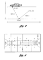
- the walking time calculations may be divided into two categories: the calculation of time required to walk between two fixed points and the calculation of time required to walk between a fixed point and a point where the operator moving at a certain velocity reaches a specific point on the vehicle, which is moving at a different velocity.
- Path 1 (the path between the two fixed points (x m , y m ) and (x k , y k )) belongs to the first type
- Path 2 (the path between the fixed point (x k , y k ) and the point at which the operator intersects the vehicle (x v , y v )) belongs to the second type.
- a fixed point can be a part bin location, a tool location, a user defined starting point or a departure point from the vehicle or any other suitable location.
- a vehicle may be divided into several zones. We may approximate the install location of the part by the centre point of the zone in which that install location resides.
- Figure 3 is an example of a vehicle divided into thirteen zones. So, for example, if the operator was installing a rear bumper, the appropriate zone would be zone 12.
- Variables whose values may be input by a user or read from a database include:
- Variables whose values may be obtained in the course of the calculations include:
- t p 1 ⁇ o ( x m - x k ) 2 + ( y m - y k ) 2 .
- t c is the time that the operator needs to walk from point ( x k ,y k ), leaving at time t I to zone j of the vehicle.
- t c is the time that the operator needs to walk from point ( x k ,y k ), leaving at time t I to zone j of the vehicle.
- t m the time that the operator needs to walk from point ( x k ,y k ), leaving at time t I to zone j of the vehicle.
- t m where the operator intersects the vehicle, but we do know that this point equals the distance that the vehicle will have travelled to get to this point x m plus an offset based on the initial position of the vehicle and on the location of the vehicle zone to which the operator is directed.
- the distance travelled by the vehicle is given by the velocity of the vehicle times the total time t T that will have elapsed by the time the operator reaches the vehicle zone to which he/she is directed.
- t T represents the total time required to reach x m (the unknown point)
- x m t T v c +x c +z x (j)
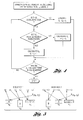
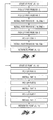
- the flowchart in Figure 4 describes a preferred method for calculating the entire time necessary to perform all tasks in a given sequence and for a given cell layout. We iterate over all tasks in a prescribed sequence, calculating the time the operator needs to walk between locations where the known walking tasks must be performed.
- the total cycle time can be calculated by determining whether the path associated to each operation that involves walking is between two fixed points (Path 1 in Figure 2) or between a fixed point and a point on the moving vehicle (Path 2 in Figure 2). Then for each operation in the sequence one determines the time at which that operation ends (running time): for operations that involve walking formula (2) is used for paths between two fixed points, formulas (5) and (6) are used for paths between a fixed point and a point on the moving vehicle.
- the total cycle time for a given sequence of operations is equal to the running time at the end of the sequence.
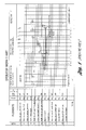
- Figures 8 and 9 show simple examples of sequences of operations for a given workcell.
- This section we describe a preferred methodology for minimizing an operator's walking time, which is considered non-value added time.
- This reduction in walking time can be accomplished in one embodiment by changing the sequence of tasks and/or rearranging the location of the part bins.
- Figure 5 shows two possible paths associated with the sequence, and of course, there are many more.
- the first formulation minimizes the walking time without ensuring that the part bins are completely contained in the workcell and do not overlap.
- the second formulation assumes that the part bins are in a line in the x-direction, they do not overlap in the x-direction, and they are completely contained in the workcell.
- the third formulation assumes that the part bins can be anywhere in the workcell as long as they are completely contained in the workcell, but if they overlap in the y-direction, then they cannot overlap in the x-direction and vice versa.
- the objective function is to minimize the total cycle time, which is the time it takes an operator to complete all tasks.
- t I is the total path time and is a function of all of the x-coordinates representing the centre point of the different part bin locations and also a function of all of similar y-coordinates for the third formulation.
- the first formulation is an unconstrained nonlinear programming problem (NLP) that minimizes the operator 's path time.
- NLP nonlinear programming problem
- One methodology for solving this problem includes using the downhill simplex method in multi-dimensions.
- the second formulation yields a constrained NLP that minimizes the operator's path time, while guaranteeing that the part bins do not overlap in the x-direction and are completely contained in the workcell.
- L i is the length of the part bins in the x-direction
- L x is the length of the workcell in the x-direction
- x i are the decision variables that yield the x-coordinate positions for the centre of the part bins.
- the third problem formulation makes sure that if the part bins overlap in the x direction, then they do not overlap in the y direction and vice versa. If the z direction is relevant, i.e., if part bins are allowed to be stacked on top of one another, this formulation can still be used. Furthermore, the formulation guarantees that the bins are a specified distance away from the assembly line; we refer to this distance as ⁇ , where 0 . ⁇ . max i LBY i and LBY i is the length of bin i in the y-direction.
- Other input variables are LBX i , the length of bin i in the x-direction; n , the number of bins; L x , the length of the workcell in the x-direction; and L y , the length of the workcell in the y-direction.
- the x and y decision variables are continuous variables that represent the x and y coordinates of the centre of the part bins.
- the p and q decision variables are binary variables used to guarantee that the bins can overlap in at most one direction. This can be formulated as a nonlinear mixed integer programming problem (MINLP) with n 2 +n variables and n ( n -1)[ n ( n -1)+1] / 2 constraints.
- MINLP nonlinear mixed integer programming problem
- Constraint 6 is similar, but for the y-direction. Constraint 7 guarantees that the bins do not overlap in at least one direction because p+q must be at least one.
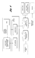
- FIG. 6 exhibits the preferred system architecture for the present invention.
- the architecture is that of a typical Web client/server system.
- the server script dynamically generates a VRML scene, such as the example VRML screen illustrated in Figure 7, from a set of predefined three-dimensional objects using information about their spatial and temporal relations. This information may be input by a user or retrieved from a database.
- VRML approximates most of the objects, using basic geometrical shapes, such as boxes. However, in some instances it is desirable to use an image that is close to the actual object in order to improve the conceptual understanding of the scene. For example, substituting a geometric shape with a three-dimensional image of the actual vehicle being assembled may help to improve the accuracy of the study. Fortunately, most three-dimensional vehicle images can be easily accessed and exported/imported to VRML.
- the operator path is calculated according to algorithm described above and superimposed on the workcell image (see Figure 7). This algorithm may be implemented in a Java class. The user can then interactively rearrange the locations of the part bins, tools, initial vehicle, and operator locations by clicking and dragging corresponding objects in the VRML scene.
- VRML generates an event with drag , which triggers recalculation of the operator walk path simultaneously with its visual adjustment.
- This allows for "what if" analysis to be accomplished in a very rapid manner compared to the manual paper and pencil method.
- the user can drag the object along a plane, which is the most often used function in the workcell planning what-if analysis.
- the user may switch this default behaviour associated with the drag action to movement in the vertical direction or rotation of the object (this vertical movement represents part bins that may be located on a shelf or parts arriving on a conveyor belt, etc.).
- the user can analyze how the speed of the line affects an operator's walking time (workload) by increasing or decreasing the line speed.
- an operator can use an "advice” button that suggests an arrangement of parts based on the optimization routines discussed above.
- the system also provides the capability to simulate the assembly operation. This capability is implemented using the VRML animation technique. Simulation allows the user to study the details of an operator's moves, according to MODAPTS rules, within the workcell synchronized with the move of the unit. This feature is very useful for validating the input data and feasibility of the given workcell arrangement, especially for complex operator paths. It can also be used to see how the design of a given workcell affects neighbouring workcells.
- the user can save the results back into a database.
- This may be done through a Java class, which queries VRML to obtain current locations of the cell objects and updates the database.
- Information maintained in the database could be used for future workcell planning, analysis and improvement.
- the interface is a three-dimensional visualization tool. Hence, several views can be obtained and printed, including the two-dimensional for a markup study or to be posted on the wall for the operator's use.
- the example HTML page contains both a VRML and Java class, which may be linked through EAI.
- the Java applet shows some aggregate information on the critical parameters of the workcell, such as unit cycle time, operator cycle time, walk time, and line speed. These parameters dynamically change with the changes in workcell arrangement.
- the Java panel may additionally contain a set of control buttons for line speed adjustment, simulation, three-dimensional object manipulations, and communication of the results back to the database.
- One of the main advantages of the proposed system is that it integrates a Web-based client server, a Virtual Reality interface, and mathematical models so that workcell arrangement can be designed, analyzed, simulated, documented, and maintained over corporate networks. This allows the workcell planning tool to efficiently interface with and complement other corporate systems involved in workcell studies.
- the present invention may be closely tied to a global study process allocation system, which maintains the information pertaining to the assembly process, including the sequence of steps for an operator with associated MODAPTS strings, the tools and parts required, and the position of the cell within the line.
- the process allocation system alone does not have the details on the geometry and locations of the specific workcell objects, and thus, can provide only average estimates for many operations, including operator walk time. Integrating the process allocation system with the present invention overcomes these problems.
- ROBCAD allows development and comprehensive analysis of the detailed models of assembly operation. Problems associated with ROBCAD that may be addressed by the present invention include: (1) the development of a ROBCAD model of an assembly plant workcell is very time consuming, even for well-trained and experienced engineers; (2) the changes made to the workcell at the plant level quite often are not communicated to ROBCAD analysts, which in turn diminishes the accuracy of the study. With the proposed system, the ROBCAD model can be automatically generated from the database (by generating robface and path files), which contains accurate data (since it is maintained at the plant floor level).
- the tool may be used in several other creative ways.
- the tool may give feedback to material control on whether or not proposed packages fit in the workcell.
- the tool may be used as a "visual" Quality Process Sheet (QPS) training aid.
- QPS Quality Process Sheet
- a QPS contains the breakdown of work into elements as specified by the operator.
- a plan view "snapshot" of the operator's workcell layout could also be pasted to the operations e-QPS sheet so that the workcell operation could be reviewed in various positions.
- one objective of the present invention is to minimize non-value added operations through a better workcell arrangement.
- One manner in which the present invention achieves this goal is by enabling a user to minimize operator walk time. For example, the user can rearrange the order of tasks an operator would perform or change the placement of parts and tools inside the workcell to find an arrangement that minimizes the walking time for an operator on the plant floor. Minimizing non-value added operations is also advantageous because it allows an operator to concentrate more on performing his or her task more effectively, yielding a better product.
- the present invention utilizes mathematic algorithms to compute an operator's walking time and path calculations for a given cell layout, including the movement and location of workcell contents, such as part bins and tools.
- Another aspect of the present invention is a virtual reality interface that generates a three-dimensional workcell scene.
- this scene displays the path calculations made by the mathematical modelling program in the background. This aspect is advantageous because it enables a user to interactively rearrange the workcell layout in an effort to arrive at the most efficient layout.
- An advantage of the present invention is its flexibility and ease of use. This advantage allows users, such as workcell operators, to utilize the present invention with minimal or no prior training. Enabling operators themselves to utilize the present invention also takes advantage of the operators' practical knowledge and experience.
- One embodiment of the present invention allows for real-time scenario planning by providing instantaneous calculations of the total time required to perform the tasks assigned to that workcell and of the total walking time. This feature allows the user to quickly evaluate a large variety of possibilities, a process that is very difficult using prior art methods.
- aspects of the present invention may be implemented on a web-based or other network platform so that aspects of the invention are not tied to any specific piece of hardware, and as a result, may be universally accessible.
- Changes made by a user may be stored in a central database so that updated information is not lost. This feature allows for propagation of best part allocations and of optimal walking paths from worker to worker.
- Another aspect of the present invention supports simulation of the operator walk through a VRML interface. This feature allows users to see how their work plans affect neighbouring operator workcells.
- the present invention may provide advice on walk path optimization with respect to given layout/process constraints by using a host of mathematical optimization methods well known to those versed in the art. This feature greatly cuts down the inefficiencies arising from prior art methods and practices.
Landscapes
- Engineering & Computer Science (AREA)
- Business, Economics & Management (AREA)
- Human Resources & Organizations (AREA)
- Strategic Management (AREA)
- Theoretical Computer Science (AREA)
- Economics (AREA)
- Entrepreneurship & Innovation (AREA)
- Physics & Mathematics (AREA)
- General Physics & Mathematics (AREA)
- Educational Administration (AREA)
- Development Economics (AREA)
- Tourism & Hospitality (AREA)
- Marketing (AREA)
- Game Theory and Decision Science (AREA)
- General Business, Economics & Management (AREA)
- Quality & Reliability (AREA)
- Operations Research (AREA)
- Computer Hardware Design (AREA)
- Evolutionary Computation (AREA)
- Geometry (AREA)
- General Engineering & Computer Science (AREA)
- General Factory Administration (AREA)
- Processing Or Creating Images (AREA)
Applications Claiming Priority (2)
| Application Number | Priority Date | Filing Date | Title |
|---|---|---|---|
| US270969 | 2002-10-15 | ||
| US10/270,969 US7092854B2 (en) | 2002-10-15 | 2002-10-15 | Computer-implemented method and system for designing a workcell layout |
Publications (2)
| Publication Number | Publication Date |
|---|---|
| EP1411451A2 true EP1411451A2 (de) | 2004-04-21 |
| EP1411451A3 EP1411451A3 (de) | 2006-06-28 |
Family
ID=32042906
Family Applications (1)
| Application Number | Title | Priority Date | Filing Date |
|---|---|---|---|
| EP03103725A Withdrawn EP1411451A3 (de) | 2002-10-15 | 2003-10-08 | System und Methode für das Design einer Arbeitszellen-Anordnung |
Country Status (2)
| Country | Link |
|---|---|
| US (1) | US7092854B2 (de) |
| EP (1) | EP1411451A3 (de) |
Cited By (1)
| Publication number | Priority date | Publication date | Assignee | Title |
|---|---|---|---|---|
| EP4553595A1 (de) * | 2023-11-13 | 2025-05-14 | ABB Schweiz AG | Konfigurationsverfahren und werkzeug zur konfiguration einer linearmotoranwendung |
Families Citing this family (7)
| Publication number | Priority date | Publication date | Assignee | Title |
|---|---|---|---|---|
| JP2003015724A (ja) * | 2001-07-03 | 2003-01-17 | Toyota Motor Corp | 使用部品群から作業時間群を算出するコンピュータ |
| JP2003015723A (ja) * | 2001-07-03 | 2003-01-17 | Toyota Motor Corp | ビジュアル表示画面を利用する作業配分立案支援装置 |
| US20040210464A1 (en) * | 2002-12-12 | 2004-10-21 | Belanger Joseph Joey Yves | System, method and computer product for implementing engineered labour standards |
| US20060250401A1 (en) * | 2005-05-06 | 2006-11-09 | Patrick Pannese | Systems and methods for generating 3D simulations |
| US8577886B2 (en) * | 2004-09-15 | 2013-11-05 | Within3, Inc. | Collections of linked databases |
| GB201116443D0 (en) * | 2011-09-23 | 2011-11-02 | Airbus Operations Ltd | Installation optimisation |
| US12142145B2 (en) * | 2019-12-27 | 2024-11-12 | Nissan Motor Co., Ltd. | Information processing method, information processing system, information processing device, and information terminal |
Family Cites Families (5)
| Publication number | Priority date | Publication date | Assignee | Title |
|---|---|---|---|---|
| US5623413A (en) * | 1994-09-01 | 1997-04-22 | Harris Corporation | Scheduling system and method |
| US6470301B1 (en) * | 1999-10-08 | 2002-10-22 | Dassault Systemes | Optimization tool for assembly workcell layout |
| US6671538B1 (en) * | 1999-11-26 | 2003-12-30 | Koninklijke Philips Electronics, N.V. | Interface system for use with imaging devices to facilitate visualization of image-guided interventional procedure planning |
| US6516242B1 (en) * | 2000-01-18 | 2003-02-04 | Dell Usa, L.P. | Apparatus for consolidating manufacturing of computing devices |
| JP4139042B2 (ja) * | 2000-04-26 | 2008-08-27 | 本田技研工業株式会社 | 工数管理システム |
-
2002
- 2002-10-15 US US10/270,969 patent/US7092854B2/en not_active Expired - Fee Related
-
2003
- 2003-10-08 EP EP03103725A patent/EP1411451A3/de not_active Withdrawn
Non-Patent Citations (1)
| Title |
|---|
| None * |
Cited By (1)
| Publication number | Priority date | Publication date | Assignee | Title |
|---|---|---|---|---|
| EP4553595A1 (de) * | 2023-11-13 | 2025-05-14 | ABB Schweiz AG | Konfigurationsverfahren und werkzeug zur konfiguration einer linearmotoranwendung |
Also Published As
| Publication number | Publication date |
|---|---|
| US20040073478A1 (en) | 2004-04-15 |
| EP1411451A3 (de) | 2006-06-28 |
| US7092854B2 (en) | 2006-08-15 |
Similar Documents
| Publication | Publication Date | Title |
|---|---|---|
| Chau et al. | 4D dynamic construction management and visualization software: 1. Development | |
| US5761674A (en) | Integrated construction project information management system | |
| Banks | Software for simulation | |
| US7406475B2 (en) | Software tool for heuristic search methods | |
| WO2002091300A2 (en) | Text overlay for multi-dimensional construction project models | |
| Kamat | VITASCOPE: Extensible and scalable 3D visualization of simulated construction operations | |
| US20100077377A1 (en) | System and Method for Creating Intelligent Simulation Objects Using Graphical Process Descriptions | |
| Lee | Real-time manufacturing modeling and simulation framework using augmented reality and stochastic network analysis | |
| JP2003044115A (ja) | 製造ライン設計方法及びその装置並びに工程設計方法 | |
| US7092854B2 (en) | Computer-implemented method and system for designing a workcell layout | |
| Vanegas et al. | Using simulation and visualization technologies to strengthen the design/construction interface | |
| Bowden | The spectrum of simulation software. | |
| Lefort et al. | Interactive virtual factory for design of a shopfloor using single cluster analysis | |
| US20090094574A1 (en) | System and method for creating intelligent simulation objects using graphical process descriptions | |
| Pinedo et al. | Design issues with regard to scheduling systems in manufacturing | |
| Scurati et al. | Data+ driven pss design in collaborative virtual environments | |
| Chang et al. | The research queuing package modeling environment (RESQME) | |
| Noble | Economic design in concurrent engineering | |
| Tomar et al. | A novel step toward repetitive projects scheduling using geographic information systems | |
| He et al. | Crowd simulation using DC model and density information | |
| Metaxatos et al. | Implementing combined model of origin-destination and route choice in EMME/2 system | |
| Rodrigues | An analysis and evaluation of Discrete Production Systems: a Simulation based approach | |
| Sadeghpour | A CAD-based model for site layout | |
| Rohrer | AutoMod | |
| Merkuryeva et al. | Simulation-based environment for multi-echelon cyclic planning and optimisation |
Legal Events
| Date | Code | Title | Description |
|---|---|---|---|
| PUAI | Public reference made under article 153(3) epc to a published international application that has entered the european phase |
Free format text: ORIGINAL CODE: 0009012 |
|
| AK | Designated contracting states |
Kind code of ref document: A2 Designated state(s): AT BE BG CH CY CZ DE DK EE ES FI FR GB GR HU IE IT LI LU MC NL PT RO SE SI SK TR |
|
| AX | Request for extension of the european patent |
Extension state: AL LT LV MK |
|
| RIC1 | Information provided on ipc code assigned before grant |
Ipc: G05B 19/418 20060101ALI20060303BHEP Ipc: G06F 17/50 20060101AFI20040212BHEP |
|
| PUAL | Search report despatched |
Free format text: ORIGINAL CODE: 0009013 |
|
| AK | Designated contracting states |
Kind code of ref document: A3 Designated state(s): AT BE BG CH CY CZ DE DK EE ES FI FR GB GR HU IE IT LI LU MC NL PT RO SE SI SK TR |
|
| AX | Request for extension of the european patent |
Extension state: AL LT LV MK |
|
| 17P | Request for examination filed |
Effective date: 20061023 |
|
| 17Q | First examination report despatched |
Effective date: 20061120 |
|
| AKX | Designation fees paid |
Designated state(s): DE FR GB |
|
| STAA | Information on the status of an ep patent application or granted ep patent |
Free format text: STATUS: THE APPLICATION IS DEEMED TO BE WITHDRAWN |
|
| 18D | Application deemed to be withdrawn |
Effective date: 20070531 |