EP1409059B9 - Enveloppe de catheter - Google Patents
Enveloppe de catheter Download PDFInfo
- Publication number
- EP1409059B9 EP1409059B9 EP01937458A EP01937458A EP1409059B9 EP 1409059 B9 EP1409059 B9 EP 1409059B9 EP 01937458 A EP01937458 A EP 01937458A EP 01937458 A EP01937458 A EP 01937458A EP 1409059 B9 EP1409059 B9 EP 1409059B9
- Authority
- EP
- European Patent Office
- Prior art keywords
- support member
- elongate
- elongate support
- flange
- catheter
- Prior art date
- Legal status (The legal status is an assumption and is not a legal conclusion. Google has not performed a legal analysis and makes no representation as to the accuracy of the status listed.)
- Expired - Lifetime
Links
- 0 *N1*CCCCCCC1 Chemical compound *N1*CCCCCCC1 0.000 description 4
Images


Classifications
-
- A—HUMAN NECESSITIES
- A61—MEDICAL OR VETERINARY SCIENCE; HYGIENE
- A61M—DEVICES FOR INTRODUCING MEDIA INTO, OR ONTO, THE BODY; DEVICES FOR TRANSDUCING BODY MEDIA OR FOR TAKING MEDIA FROM THE BODY; DEVICES FOR PRODUCING OR ENDING SLEEP OR STUPOR
- A61M25/00—Catheters; Hollow probes
- A61M25/0043—Catheters; Hollow probes characterised by structural features
-
- A—HUMAN NECESSITIES
- A61—MEDICAL OR VETERINARY SCIENCE; HYGIENE
- A61M—DEVICES FOR INTRODUCING MEDIA INTO, OR ONTO, THE BODY; DEVICES FOR TRANSDUCING BODY MEDIA OR FOR TAKING MEDIA FROM THE BODY; DEVICES FOR PRODUCING OR ENDING SLEEP OR STUPOR
- A61M25/00—Catheters; Hollow probes
- A61M25/0021—Catheters; Hollow probes characterised by the form of the tubing
- A61M25/0023—Catheters; Hollow probes characterised by the form of the tubing by the form of the lumen, e.g. cross-section, variable diameter
- A61M25/0026—Multi-lumen catheters with stationary elements
- A61M2025/0034—Multi-lumen catheters with stationary elements characterized by elements which are assembled, connected or fused, e.g. splittable tubes, outer sheaths creating lumina or separate cores
-
- A—HUMAN NECESSITIES
- A61—MEDICAL OR VETERINARY SCIENCE; HYGIENE
- A61M—DEVICES FOR INTRODUCING MEDIA INTO, OR ONTO, THE BODY; DEVICES FOR TRANSDUCING BODY MEDIA OR FOR TAKING MEDIA FROM THE BODY; DEVICES FOR PRODUCING OR ENDING SLEEP OR STUPOR
- A61M25/00—Catheters; Hollow probes
- A61M25/0043—Catheters; Hollow probes characterised by structural features
- A61M2025/0063—Catheters; Hollow probes characterised by structural features having means, e.g. stylets, mandrils, rods or wires to reinforce or adjust temporarily the stiffness, column strength or pushability of catheters which are already inserted into the human body
-
- A—HUMAN NECESSITIES
- A61—MEDICAL OR VETERINARY SCIENCE; HYGIENE
- A61M—DEVICES FOR INTRODUCING MEDIA INTO, OR ONTO, THE BODY; DEVICES FOR TRANSDUCING BODY MEDIA OR FOR TAKING MEDIA FROM THE BODY; DEVICES FOR PRODUCING OR ENDING SLEEP OR STUPOR
- A61M25/00—Catheters; Hollow probes
- A61M25/0021—Catheters; Hollow probes characterised by the form of the tubing
- A61M25/0023—Catheters; Hollow probes characterised by the form of the tubing by the form of the lumen, e.g. cross-section, variable diameter
- A61M25/0026—Multi-lumen catheters with stationary elements
- A61M25/0032—Multi-lumen catheters with stationary elements characterized by at least one unconventionally shaped lumen, e.g. polygons, ellipsoids, wedges or shapes comprising concave and convex parts
-
- A—HUMAN NECESSITIES
- A61—MEDICAL OR VETERINARY SCIENCE; HYGIENE
- A61M—DEVICES FOR INTRODUCING MEDIA INTO, OR ONTO, THE BODY; DEVICES FOR TRANSDUCING BODY MEDIA OR FOR TAKING MEDIA FROM THE BODY; DEVICES FOR PRODUCING OR ENDING SLEEP OR STUPOR
- A61M25/00—Catheters; Hollow probes
- A61M25/01—Introducing, guiding, advancing, emplacing or holding catheters
- A61M25/06—Body-piercing guide needles or the like
- A61M25/0662—Guide tubes
Definitions
- the present invention relates generally to catheters for performing medical procedures.
- Intravascular catheters are currently utilized in a wide variety of minimally-invasive medical procedures.
- an intravascular catheter enables a physician to remotely perform a medical procedure by inserting the catheter into the vascular system of the patient at an easily accessible location and navigating the tip of the catheter to the desired target site.
- virtually any target site in the patient's vascular system may be remotely accessed, including the coronary, cerebral, and peripheral vasculature.
- the catheter enters the patient's vasculature at a convenient location such as a blood vessel in the neck or near the groin.
- a convenient location such as a blood vessel in the neck or near the groin.
- the physician may urge the distal tip forward by applying longitudinal forces to the proximal portion of the catheter.
- the catheter to effectively communicate these longitudinal forces it is desirable that the catheter have a high level of pushability and kink resistance particularly near the proximal end.
- intravascular catheters be very flexible, particularly near the distal end.
- the distal portion of the catheter may include a plurality of bends or curves. Torsional forces applied on the proximal end must translate to the distal end to aid in steering. It is therefore desirable that the proximal portion of an intravascular catheter have a relatively high level of torquability to facilitate steering.
- the catheter may be used for various diagnostic and/or therapeutic purposes.
- a diagnostic use for an intravascular catheter is the delivery of radiopaque contrast solution to enhance fluoroscopic visualization.
- the intravascular catheter provides a fluid path leading from a location outside the body to a desired location inside the body of a patient.
- intravascular catheters be sufficiently resistant to kinking.
- intravascular catheters be sufficiently resistant to bursting or leaking.
- Examples of therapeutic purposes for intravascular catheters include percutaneous transluminal angioplasty (PTA) and percutaneous transluminal coronary angioplasty (PTCA). These angioplasty techniques typically involve the use of a guide catheter and a balloon catheter. During these procedures, the distal end of the guide catheter is typically inserted into the femoral artery located near the groin of the patient. The guide catheter is urged through the vasculature of the patient until its distal end is proximate the restriction. In many cases, the distal end of the guide catheter is positioned in the ostium of the coronary artery. The balloon catheter may then be fed through a lumen in the guide catheter such that the balloon is positioned proximate a restriction in a diseased vessel.
- PTA percutaneous transluminal angioplasty
- PTCA percutaneous transluminal coronary angioplasty
- the balloon is then inflated and the restriction in the vessel is opened.
- the guide catheter provide a low friction path for the balloon catheter.
- the balloon is inflated by urging a liquid though the elongate shaft of the balloon catheter and into the balloon.
- the balloon catheter must provide an unobstructed path for the inflation fluid. It is also desirable that the catheter be substantially free of leaks.
- the catheter have a relatively high level of pushability and torqueability, particularly near its proximal end. It is also desirable that a catheter be relatively flexible, particularly near it's distal end.
- the need for this combination of performance features is often addressed by building a catheter which has two or more discrete tubular members having different performance characteristics. For example, a relatively flexible distal section may be spliced to a relatively rigid proximal section.
- a catheter is formed from two or more discrete tubular members, it is often necessary to form a bond between the distal end of one tubular member and the proximal end of another tubular member.
- Intravascular catheters are often used in conjunction with a guidewire.
- the guidewire may be advanced through the patient's vasculature until its distal tip has reached a desired target location. Once the distal portion of the guidewire is proximate the desired location, the catheter may be threaded onto the guidewire and urged distally until the distal end of the catheter is proximate the target location.
- Intravascular catheters adapted for use with a guidewire typically fall into one of two categories: the over-the-wire category or the single operator exchange (SOB) category.
- An over-the wire type of catheter includes a guidewire lumen extending from the distal tip of the catheter to the proximal end of the catheter.
- a single operator exchange catheter typically includes a relatively short guidewire lumen proximate the distal end of the catheter.
- the guidewire In order to keep the guidewire tip near the target area, the guidewire must be held in place throughout the catheter exchange procedure. A portion of the guidewire is typically grasped by the physician in order to withdraw the first catheter while maintaining distal end of the guidewire in the desired position. To properly anchor the guidewire, a portion of the guidewire must be exposed at all times so it is available for the physician to grasp. In the case of an over-the-wire catheter, this requires that the length of the guidewire extending beyond the patient's body be longer than the catheters. In some cases, length must be added to the guidewire using a guidewire extension. In many cases intravascular catheters are longer than 200 cm. Correspondingly, there may be more than 200 cm of wire extending from the patient. Managing this length of wire during a catheter exchange procedure is awkward, and typically requires two persons. In particular, contamination must be avoided by assuring that the guidewire is not dropped from the sterile field.
- An SOE catheter has a relatively short guidewire wire lumen proximate its distal tip.
- the length of guidewire extending beyond the body of the patient need only be slightly longer than the guidewire lumen of the catheter.
- the physician may anchor or hold the guidewire as the first catheter is removed from the body with the exchange occurring over the shorter guidewire lumen.
- the guidewire lumen of an SOB catheter typically includes a distal guidewire port disposed at the distal tip of the catheter and a proximal guidewire port disposed proximally of the distal end of the catheter. It is desirable to fabricate an SOE catheter, to include a proximal guidewire port, while maintaining the other desirable performance features described previously.
- US-A-4846791 describes a multi-lumen catheter formed by first introducing one end of an extendable tube into a blood vessel and then inserting a divider into the distal end of the tube extending the length of the tube, thereby dividing the tube into a plurality of separate lumens.
- This document does not disclose the features of claim 1 that the elongate support member is made from metal and that is central portion lies off the center of gravity of the catheter shaft.
- US-A-5490845 describes a flexible catheter comprising a flexible, cylindrical member having a bore therethrough and including an intra-luminal chord within the wall of the cylindrical member or the lumen of the cylindrical member to prevent the collapse thereof and facilitate the removal of broken portions thereof.
- WO 00/33910 is a prior art in terms of Art. 54(3) EPC. It describes catheters having improved flexibility control, which can be provided by a slidable core wire disposed within the catheter and by shafts formed from segmented spine wires disposed within polymeric tubes.
- the present invention relates to a catheter shaft as defined in claim 1. More particularly, the present invention relates to a catheter shaft including one or more elongate support members.
- An elongate support member in accordance with one embodiment of the present invention comprises a first flange, a second flange, and a central member extending between the first flange and the second . flange.
- the first flange and the second flange define an elongate channel having an elongate opening.
- An inflation conduit defining an inflation lumen is disposed in elongate channel. During the assembly of proximal shaft portion, the inflation conduit may be passed through elongate opening and laid in the elongate channel.
- a sheath is disposed about the elongate support member and the inflation conduit.
- the first flange and the second flange of the elongate support member each have a free end proximate the elongate opening of the elongate channel and a fixed end which is fixed to the central, member of the elongate support member.
- the elongate support member is comprised of a mental such as stainless steel, nickel titanium alloys, other alloys, etc.
- the elongate support member may absorb the energy of bending through deformation of the first flange and the second flange.
- the free end of the first flange is free to move relative to the free end of the second flange. Bending energy applied to the elongate support member may be absorbed as the free end of the first flange and the free end of the second flange move relative to one another.
- the ability of the elongate support member to absorb bending energy may enhance the kink resistance, fracture resistance, and/or toughness of a catheter including the elongate support member.
- the elongate support member preferably, includes a right portion comprising one or more flanges extending beyond a right side of a first central plane extending through a longitudinal axis of the elongate support member and a left portion comprising one or more flanges extending beyond a left side of the first central plane. Additionally, the elongate support member includes a ventral portion comprising one or more flanges extending beyond a ventral side of a second central plane extending through a longitudinal axis of the elongate support member and a dorsal portion comprising one or more flanges extending beyond a dorsal side of the second central plane.
- the right portion has a transverse cross sectional area which is substantially equal to a transverse cross sectional area of the left portion.
- the ventral portion has a transverse cross sectional area which is substantially equal to a transverse cross sectional area of the dorsal portion.
- the transverse cross sectional area the ventral portion, the transverse cross sectional area the dorsal portion, the transverse cross sectional area the right portion, and the transverse cross sectional area the left portion are all substantially equal.
- the elongate support member resists bending along the first central plane. Also in a preferred embodiment, the elongate support member resists bending along the second central plane. In a particularly preferred embodiment, the resistance of the elongate support member to bending along second central plane is substantially equal to it's resistance to bending along first central plane. The non-preferential resistance to bending of the elongate support member may enhance the pushability and kink resistance of a catheter including the elongate support member.
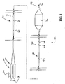
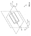
- FIG. 1 is a plan view of a catheter 50.
- Catheter 50 includes an elongate shaft 52 having a distal end 56 and a proximal end 54.
- a hub assembly 58 is disposed about elongate shaft 52, proximate proximal end 54 thereof.
- Hub assembly 58 includes a plurality of hub ports 74.
- Elongate shaft 52 includes a proximal shaft portion 60, a middle shaft portion 62, and a distal shaft portion 64.
- Proximal shaft portion 60, middle shaft portion 62, and distal shaft portion 64 each have a proximal end and a distal end.
- the distal end of proximal shaft portion 60 is fixed to the proximal end of middle shaft portion 62.
- the distal end of middle shaft portion 62 is fixed to the proximal end of distal shaft portion 64 proximate a transition region 66.
- catheter 50 may include more or less than three shaft portions .
- elongate shaft 52 of catheter 50 defines a proximal guidewire port 68.
- Catheter 50 also includes a distal guidewire port 70 disposed proximate distal end 56 of elongate shaft 52.
- Elongate shaft 52 includes a plurality of walls defining a guidewire lumen (not shown) which is in fluid communication with proximal guidewire port 68 and distal guidewire port 70.
- Elongate shaft 52 also includes a plurality of walls defining an inflation lumen 72.
- Inflation lumen 72 is in fluid communication with a hub port 74 of hub assembly 58 and a balloon 76 disposed about elongate shaft 52 proximate distal end 56.
- Hub port 74 of hub assembly 58 is adapted to couple with a fluid source.
- Balloon 76 may be inflated by urging fluid from the fluid source into balloon 76 via inflation lumen 72.
- Catheter 50 of Figure 1 is a type of catheter which may be generally referred to as a balloon catheter. It is to be appreciated that devices in accordance with the present invention may be used in conjunction with other types of catheter without deviating from the scope of the present invention.
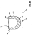
- FIG. 2A is a transverse cross-sectional view of an exemplary embodiment of a catheter shaft 100 in accordance with the present invention.
- Catheter shaft 100 may form, for example, a portion of elongate shaft 52 of catheter 50.
- proximal shaft portion 60 of elongate shaft 52 of catheter 50 comprises catheter shaft 100.
- Catheter shaft 100 includes an elongate support member 102 comprising a first flange 104, a second flange 106, and a central member 108 extending between first flange 104 and second flange 106.
- First flange 104 and a second flange 106 define an elongate channel 120 having an elongate opening 122.
- An inflation conduit 124 defining an inflation lumen 126 is disposed in elongate channel 120. During the assembly of catheter shaft 100, inflation conduit 124 may be passed through elongate opening 122 and laid in elongate channel 120. A sheath 128 is disposed about elongate support member 102 and inflation conduit 124.
- FIG. 2B is a transverse cross-sectional view of an additional exemplary embodiment of a catheter shaft 101 in accordance with the present invention.
- Catheter shaft 101 includes an elongate support member 102 comprising a first flange 104, a second flange 106, and a central member 108 extending between first flange 104 and second flange 106.
- First flange 104 and a second flange 106 define an elongate channel 120 having an elongate opening 122.
- a sheath 128 is disposed about elongate support member 102 and inflation conduit 124.
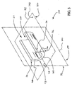
- Figure 3 is a perspective view of a portion of elongate support member 102 of catheter shaft 100.
- first flange 104 of elongate support member 102 has a free end 130 proximate elongate opening 122 of elongate channel 120 and a fixed end 132 which is fixed to central member 108 of elongate support member 102.
- second flange 106 of elongate support member 102 has a free end 134 proximate elongate opening 122 of elongate channel 120 and a fixed end 136 which is fixed to central member 108 of elongate support member 102.
- Elongate support member 102 has a longitudinal axis 138 which is shown as a dashed line in Figure .3 .
- longitudinal axis 138 extends through the center of gravity of elongate support member 102.
- a first central plane 140 is also shown with dashed lines in Figure 3 .
- First central plane 140 extends through longitudinal axis 138 of elongate support member 102.
- First central plane 140 has a right side 144 and a left side 146.
- a second central plane 142 also extends through longitudinal axis 138 of elongate support member 102 and intersects first central plane 140.
- second central plane 142 is disposed at a 90 degree angle to first central plane 140.
- Second central plane 142 has a ventral side 150 and a dorsal side 148.
- Figure 4 is a perspective view of a portion of elongate support member 102 which is bent along first central plane 140.
- elongate support member 102 is bent so that longitudinal axis 138 of elongate support member 102 defines a plane which is coplanar with first central plane 140.
- the bending of elongate support member 102 illustrated in Figure 4 is preferably elastic bending. In the case of elastic bending, elongate support member 102 will return to substantially the shape shown in Figure 3 when the bending forces are removed.
- Another type of bending is plastic bending. In the case of plastic bending, at least a portion of the deformation caused by the bending forces will remain after the bending forces are removed.
- elongate support member 102 resists bending along first central plane 140. Also in a preferred embodiment, elongate support member 102 resists bending along second central plane 142 shown in Figure 3 . In a particularly preferred embodiment, the resistance of elongate support member 102 to bending along second central plane 142 is substantially equal to it's resistance to bending along first central plane 140. The non-preferential resistance to bending of elongate support member 102 may enhance the pushability and kink resistance of a catheter including elongate support member 102.
- Figure 5 is a transverse cross-sectional view of elongate support member 102 and first central plane 140.
- first central plane 140 divides elongate support member 102 into a right portion 154 extending beyond right side 144 of first central plane 140 and a left portion 156 extending beyond left side 146 of first central plane 140.
- left portion 156 of elongate support member 102 comprises first flange 104 and a portion of central member 108.
- right portion 154 comprises second flange 106 and a portion of central member 108.
- right portion 154 has a transverse cross sectional area which is substantially equal to the transverse cross sectional area of left portion 156.
- elongate support member 102 is generally symmetrical about the first central plane 140.
- Figure 6 is a transverse cross-sectional view of elongate support member 102 and second central plane 142.
- second central plane 142 divides elongate support member 102 into a ventral portion 160 and a dorsal portion 158.
- Ventral portion 160 extends beyond ventral side 150 of second central plane 142 and dorsal portion 158 extends beyond dorsal side 148 of second central plane 142.
- dorsal portion 158 of elongate support member 102 comprises a portion of first flange 104 and a portion of second flange 106.
- Ventral portion 160 of elongate support member 102 comprises a portion of first flange 104, a portion of second flange 106, and central member 108.
- ventral portion 160 has a transverse cross sectional area which is substantially equal to the transverse cross sectional area of dorsal portion 158.
- elongate support member 102 is generally asymmetrical about second central plane 142.
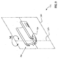
- Figure 7 is a perspective view of a segment of elongate support member 102 resting on two supports 162.
- a force F is shown acting on elongate support member 102 approximately midway between supports 162.
- the application of force F to elongate support member 102 results in a bending moment M b acting about a first bending axis 164.
- first bending axis 164 lies in second central plane 142. Bending moment M b may result in bending along first central plane 140.
- Figure .8 is an enlarged cross sectional view of a portion of elongate support member 102 taken along a sectional plane which extends through first bending axis 164.
- Second central plane 142 is also illustrated in Figure 8 , as describe previously, second central plane 142 divides elongate support member 102 into a dorsal portion 158 and a ventral portion 160.
- bending moment M b places dorsal portion 158 of elongate support member 102 in compression. Bending moment M b also places ventral portion 160 of elongate support member 102 in tension.
- ventral portion 160 preferably, has a transverse cross sectional area which is substantially equal to the transverse cross sectional area of dorsal portion 158.
- the area of elongate support member 102 in compression is substantially equal to the area of elongate support member 102 in tension.
- second central plane 142 comprises a neutral plane when support member 102 is bent along first central plane 140.
- Figure 9 is a cross sectional perspective view of a portion of elongate support member 102 taken through a sectional plane which extends through a second bending axis 166.
- second bending axis 166 lies in first central plane 140.
- first central plane 140 divides elongate support member 102 into a right portion 154 and a left portion 156.
- a bending moment M b is acting on elongate support member 102.
- bending moment M b places right portion 154 of elongate support member 102 in compression. Bending moment M b also places left portion 156 of elongate support member 102 in tension.
- right portion 154 preferably has a transverse cross sectional area which is substantially equal to the transverse cross sectional area of left portion 156.
- the area of elongate support member 102 in compression is substantially equal to the area of elongate support member 102 in tension.
- first central plane 140 comprises a neutral plane when support member 102 is bent along second central plane 142.
- the transverse cross sectional areas of left portion 156, right portion 154, ventral portion 160, and dorsal portion 158 are all substantially equal.
- the resistance of elongate support member 102 to bending along second central plane 142 is substantially equal to the bend resistance of elongate support member 102 along first central plane 140. This non-preferential resistance to bending may enhance the pushability and kink resistance of a catheter including elongate support member 102.
- Figure 10 is a transverse cross-sectional view of elongate support member 102 in a first deflected state.
- first flange 104 and second flange 106 are outwardly deflected relative to one another.
- elongate support member 102 is comprised of a somewhat springy material.
- elongate support member 102 may absorb the energy of bending through deformation of first flange 104 and second flange 106.
- the deformation may be elastic deformation or plastic deformation. Plastic deformation is deformation which will remain after the force creating the deformation is removed. Elastic deformation is deformation which disappears when the external forces are removed.
- the undeflected shape of elongate support member 102 is shown with hidden lines in Figure 10 .
- first flange 104 is free to move relative to free end 134 of second flange 106.
- Bending energy applied to elongate support member 102 may be absorbed as free end 130 of first flange 104 and free end 134 of second flange 106 move relative to one another.
- the ability of elongate support member 102 to absorb bending energy may enhance the kink resistance, fracture resistance, and/or toughness of a catheter including elongate support member 102.
- Figure 11 is a transverse cross-sectional view of elongate support member 102 in a second deflected state.
- first flange 104 and second flange 106 are deflected inward relative to one another.
- the undeflected shape of elongate support member 102 is shown with hidden lines in Figure 11 .
- FIG 12 is a transverse cross-sectional view of an additional exemplary embodiment of a catheter shaft 200 not in accordance with the present invention.
- Catheter shaft 200 includes an elongate support member 202 comprising a first flange 204, a second flange 206, a third flange 268, fourth flange 270, and a central member 208.
- Each flange includes a free end 272, and a fixed end 274 which is fixed to central member 208.
- First flange 204 and second flange 206 define a first elongate channel 220.
- Second flange 206 and third flange 268 define a second elongate channel 282.
- Third flange 268 and fourth flange 270 define a third elongate channel 284.
- Fourth flange 270 and first flange 204 define a fourth elongate channel 286.
- a sheath 228 is disposed about elongate support member 202.
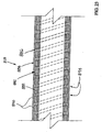
- FIG. 13 is a longitudinal cross sectional view of an exemplary embodiment of sheath 228 of Figure 12 .
- sheath 228 comprises an inner layer 80 which is overlaid by a support matrix 82.
- a jacket 84 comprising a jacket material 86 overlays support matrix 82.
- Jacket material 86 of jacket 84 is also disposed within a plurality of interstitial spaces defined by support matrix 82.
- support matrix 82 is comprised of a plurality of filaments 88.
- filaments 88 are comprised of stainless steel wire, wound in a braided pattern around inner layer 80.
- Other embodiments of support matrix 82 are possible .
- support matrix 82 may be comprised of a plurality of polymer filaments braided or knitted together.
- support matrix 82 may be comprised of polymer filaments wound in a spiral pattern around inner layer 80.
- jacket 84 is comprised of polyether block amide (PEBA).
- PEBA polyether block amide
- Polyether block amide is commercially available from Atochem Polymers of Birdsboro, Pennsylvania under the trade name PEBAX.
- Jacket 84 may be fabricated using an extrusion process. In this process, molten PEBA is extruded onto the combined layers of inner layer 80 and support matrix 82. When this process is used, the material of jacket 84 fills any interstitial spaces in support matrix 82.
- Jacket 84 may also be comprised of other materials
- materials which may be suitable in some applications include: thermoplastics, high performance engineering resins, polyethylene (PE), polypropylene (PP), polyvinylchloride (PVC), polyurethane, polytetrafluoroethylene (PTFE), polyether-ether ketone (PEEK), polyimide, polyamide, polyphenylene sulfide (PPS), polyphenylene oxide (PPO), polysufone, nylon, perfluoro(propyl vinyl ether) (PFA), and the like.
- Figure 14 is a perspective view of a portion of elongate support member 202 of Figure 12 .
- Elongate support member 202 has a longitudinal axis 238 which is shown as a dashed line in Figure 14 .
- longitudinal axis 238 extends through the center of gravity of elongate support member 202.
- a first central plane 240 is also shown with dashed lines in Figure 14 .
- First central plane 240 extends through longitudinal axis 238 of elongate support member 202.
- First central plane 240 has a right side 244 and a left side 246.
- a second central plane 242 also extends through longitudinal axis 238 of elongate support member 202 and intersects first central plane 240.
- second central plane 242 is disposed at a 90 degree angle to first central plane 240.
- Second central plane 242 has a ventral side 250 and a dorsal side 248.
- Figure 15 is a transverse cross-sectional view of elongate support member 202 and first central plane 240.
- first central plane 240 divides elongate support member 202 into a right portion 254 extending beyond right side 244 of first central plane 240 and a left portion 256 extending beyond left side 246 of first central plane 240.
- left portion 256 of elongate support member 202 comprises first flange 204, second flange 206, and a portion of central member 208.
- Right portion 254 comprises third flange 268, fourth flange 270, and a portion of central member 208.
- right portion 254 has a transverse cross sectional area which is substantially equal to the transverse cross sectional area of left portion 256.
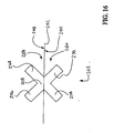
- Figure 16 is a transverse cross-sectional view of elongate support member 202 and second central plane 242.
- second central plane 242 divides elongate support member 202 into a ventral portion 260 and a dorsal portion 258.
- Ventral portion 260 extends beyond ventral side 250 of second central plane 242 and dorsal portion 258 extends beyond dorsal side 248 of second central plane 242.
- dorsal portion 258 of elongate support member 202 comprises second flange 206, third flange 268, and a portion of central member 208.
- Ventral portion 260 of elongate support member 202 comprises first flange 204, fourth flange 270, and a portion of central member 208.
- ventral portion 260 has a transverse cross sectional area which is substantially equal to the transverse cross sectional area of dorsal portion 258.
- the transverse cross sectional areas of left portion 256, right portion 254, ventral portion 260, and dorsal portion 258 are all substantially equal.
- the resistance of elongate support member 202 to bending along second central plane 242 is substantially equal to the bend resistance of elongate support member 202 along first central plane 240. This non-preferential resistance to bending may enhance the pushability and kink resistance of a catheter including elongate support member 202.
- Figure 17 is a transverse cross-sectional view of elongate support member 202 in a deflected state.
- first flange 204 and second flange 206 are inwardly deflected relative to one another.
- third flange 268 and fourth flange 270 are inwardly deflected relative to one another.
- elongate support member 202 is comprised of a somewhat springy material.
- elongate support member 202 may absorb the energy of bending through deformation of first flange 204, second flange 206, third flange 268 and fourth flange 270.
- the deformation may be elastic deformation or plastic deformation.
- the undeflected shape of elongate support member 202 is shown with hidden lines in Figure 17 .
- the free ends of the flanges are free to move relative to the fixed ends of the flanges.
- Bending energy applied to elongate support member 202 may be absorbed as the flanges deform.
- the ability of elongate support member 202 to absorb bending energy may enhance the kink resistance, fracture resistance, and/or toughness of a catheter including elongate support member 202.
- Figure 18 is a transverse cross-sectional view of an additional exemplary embodiment of catheter shaft 300 not in accordance with the present invention.
- Catheter shaft 300 includes an elongate support member 302 comprising a first flange 304, a second flange 306, a third flange 368, fourth flange 370, and a central member 308.
- Each flange includes a free end and a fixed end which is fixed to central member 308.
- first flange 304 and second flange 306 each have a generally polyhedral shape with a generally rectangular transverse cross section.
- Third flange 368 and fourth flange 370 each have a generally polyhedral shape with a generally triangular transverse cross section.
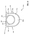
- FIG 19 is a transverse cross-sectional view of an additional exemplary embodiment of catheter shaft 400 in accordance with the present invention.
- Catheter shaft 400 includes an elongate support member 402, an inflation conduit 424, and a sheath 428 disposed about elongate support member 402 and inflation conduit 424.
- Elongate support member 402 comprises a first flange 404, a second flange 406, and a central member 408 extending between first flange 404 and second flange 406.
- First flange 404 and a second flange 406 define an elongate channel 420 having an elongate opening 422.
- First flange 404 of elongate support member 402 has a free end 472 proximate elongate opening 422 of elongate channel 420 and a fixed end 474 which is fixed to central member 408 of elongate support member 402.
- second flange 406 of elongate support member 402 has a free end 472 proximate elongate opening 422 of elongate channel 420 and a fixed end 474 which is fixed to central member 408 of elongate support member 402.
- central member 408 has a thickness which is substantially greater either the thickness of first flange 404 or the thickness of second flange 406.
- FIG. 20 is a transverse cross-sectional view of an additional exemplary embodiment of catheter shaft 500 in accordance with the present invention.
- Catheter shaft 500 includes an elongate support member 502, an inflation conduit 524, and a sheath 528 disposed about elongate support member 502 and inflation conduit 524.
- Elongate support member 502 comprises a first ridge portion 576, a second ridge portion 578, and a central portion 580 extending between first ridge portion 576 and second ridge portion 578.
- First ridge portion 576, second ridge portion 578, and central portion 580 define an elongate channel 520 having an elongate opening 522.
- Inflation conduit 524 is partially disposed within elongate channel 520.
- FIG 21 is a transverse cross-sectional view of an additional exemplary embodiment of catheter shaft 600 not in accordance with the present invention.
- Catheter shaft 600 includes an elongate support member 602, an inflation conduit 624, and a sheath 628 disposed about elongate support member 602 and inflation conduit 624.
- elongate support member 602 and inflation conduit 624 each have a generally D-shaped cross section.
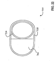
- FIG 22 is a transverse cross-sectional view of an additional exemplary embodiment of catheter shaft 700 not in accordance with the present invention.
- Catheter shaft 700 includes an elongate support member 702, an inflation conduit 724, and a sheath 728 disposed about elongate support member 702 and inflation conduit 724.
- elongate support member 702 has a generally D-shaped cross section
- inflation conduit 724 has a generally elliptical cross section.
- FIG 23 is a longitudinal cross sectional view of an exemplary embodiment of a sheath 828 .
- sheath 828 includes a support matrix 882 disposed within a jacket 884 comprising a jacket material 886.
- Support matrix 882 comprises a ribbon 888, preferably having a generally helical shape, forming a plurality of turns 890.
- Support matrix 882 also includes a plurality of gaps 894 defined by adjacent turns 890 of ribbon 888.
- jacket material 886 of jacket 884 extends into gaps 894.
- jacket material 886 comprises polyether block amide (PEBA).
- PEBA polyether block amide
- Polyether block amide is commercially available from Atochem Polymers of Birdsboro, Pennsylvania under the trade name PEBAX.
- Jacket 884 may be fabricated using an extrusion process. In this process, molten PEBA may be extruded over support matrix 882 filling gaps 894. Jacket 884 may also be comprised of other materials.
- thermoplastics high performance engineering resins
- PE polyethylene
- PP polypropylene
- PVC polyvinylchloride
- PVC polyurethane
- PTFE polytetrafluoroethylene
- PEEK polyether-ether ketone
- polyimide polyamide
- PPS polyphenylene sulfide
- PPO polyphenylene oxide
- polysufone nylon, perfluoro(propyl vinyl ether) (PFA), and the like.
- ribbon 888 comprises a metal.
- Particularly preferred metals include stainless steel, nickel-titanium alloy, nickel alloys, and titanium alloys.
- FIG 24 is a longitudinal cross sectional view of an additional exemplary embodiment of a sheath 928.
- sheath 928 includes a support matrix 982 disposed within a jacket 984 comprising a jacket material 986.
- Support matrix 982 comprises a wall 992 defining a plurality of perforations 994.
- each perforation 994 comprises a generally circular hole 996.
- jacket material 986 of jacket 984 extends into perforations 994 defined by wall 992 of support matrix 982. It is to be understood that perforations 994 may be any shape.
- Jacket material 986 may comprise various materials .
- thermoplastics high performance engineering resins
- PE polyethylene
- PP polypropylene
- PVC polyvinylchloride
- PVC polyurethane
- PTFE polytetrafluoroethylene
- PEEK polyether-ether ketone
- polyimide polyamide
- PPS polyphenylene sulfide
- PPO polyphenylene oxide
- PEBA polyether block amide
Claims (10)
- Corps de cathéter comprenant :un membre de support métallique allongé (102) comprenant une extrémité distale, une extrémité proximale, plusieurs brides allongées (104, 106) s'étendant entre elles, et une portion centrale (108), lesdites plusieurs brides allongées (104, 106) possédant une extrémité fixe et une extrémité libre, l'extrémité fixe de chaque bride étant fixée à la portion centrale (108), la portion centrale (108) étant disposée en dehors du centre de gravité dudit corps de cathéter ;un canal allongé (120) défini au sein du membre du support métallique allongé (102), le canal allongé (120) possédant une ouverture allongée (122) ;une lumière de gonflage (126) disposée au sein du canal allongé (120) ; etune gaine (128) disposée autour du membre de support allongé (102).
- Corps de cathéter selon la revendication 1, dans lequel le membre de support métallique allongé (102) comprend de l'acier inoxydable, un alliage à base de nickel ou bien un alliage de nickel et de titane.
- Corps de cathéter selon la revendication 1, dans lequel la gaine (128) comprend de la polyétheréther cétone, du polyimide, du polyphénylène sulfure ou du perfluoro(propyl vinyl éther).
- Corps de cathéter selon la revendication 1, dans lequel lesdites plusieurs brides allongées (104, 106) définissent le canal allongé (120) possédant l'ouverture allongée (122).
- Corps de cathéter selon la revendication 1, dans lequel ledit au moins un canal allongé (120) s'étend entre l'extrémité proximale du membre de support (102) et l'extrémité distale du membre de support (102).
- Corps de cathéter selon la revendication 1, dans lequel l'ouverture allongée (122) du canal allongé (120) s'étend entre l'extrémité proximale du membre de support (102) et l'extrémité distale du membre de support (102).
- Corps de cathéter selon la revendication 1, dans lequel l'ouverture allongée (122) du canal allongé (120) est disposée entre les extrémités libres desdites plusieurs brides (104, 106).
- Corps de cathéter selon la revendication 1, dans lequel les brides (104, 106) sont conçues pour absorber l'énergie de flexion lors de la flexion du membre de support (102).
- Corps de cathéter selon la revendication 1, dans lequel les brides (104, 106) sont conçues pour s'infléchir lors de la flexion du membre de support (102).
- Corps de cathéter selon la revendication 1, dans lequel les extrémités distales des brides (104, 106) sont conçues pour se déplacer l'une par rapport à l'autre lors de la flexion du membre de support allongé (102).
Applications Claiming Priority (3)
| Application Number | Priority Date | Filing Date | Title |
|---|---|---|---|
| US593193 | 1990-10-05 | ||
| US09/593,193 US6475184B1 (en) | 2000-06-14 | 2000-06-14 | Catheter shaft |
| PCT/US2001/015854 WO2001095974A1 (fr) | 2000-06-14 | 2001-05-17 | Enveloppe de catheter |
Publications (3)
| Publication Number | Publication Date |
|---|---|
| EP1409059A1 EP1409059A1 (fr) | 2004-04-21 |
| EP1409059B1 EP1409059B1 (fr) | 2009-04-29 |
| EP1409059B9 true EP1409059B9 (fr) | 2009-09-23 |
Family
ID=24373762
Family Applications (1)
| Application Number | Title | Priority Date | Filing Date |
|---|---|---|---|
| EP01937458A Expired - Lifetime EP1409059B9 (fr) | 2000-06-14 | 2001-05-17 | Enveloppe de catheter |
Country Status (7)
| Country | Link |
|---|---|
| US (1) | US6475184B1 (fr) |
| EP (1) | EP1409059B9 (fr) |
| AT (1) | ATE429945T1 (fr) |
| AU (1) | AU2001263195A1 (fr) |
| DE (1) | DE60138574D1 (fr) |
| ES (1) | ES2324977T3 (fr) |
| WO (1) | WO2001095974A1 (fr) |
Families Citing this family (33)
| Publication number | Priority date | Publication date | Assignee | Title |
|---|---|---|---|---|
| US7018401B1 (en) | 1999-02-01 | 2006-03-28 | Board Of Regents, The University Of Texas System | Woven intravascular devices and methods for making the same and apparatus for delivery of the same |
| EP1435253B1 (fr) | 2002-12-31 | 2007-01-17 | Abbott Laboratories Vascular Enterprises Limited | Cathéter avec partie plus flexible entre la tige et la pointe distale et procédé de fabrication |
| US7491213B2 (en) * | 2004-01-13 | 2009-02-17 | Boston Scientific Scimed, Inc. | Catheter shaft having distal support |
| US7794448B2 (en) | 2004-05-27 | 2010-09-14 | Abbott Laboratories | Multiple lumen catheter and method of making same |
| US7785318B2 (en) | 2004-05-27 | 2010-08-31 | Abbott Laboratories | Catheter having plurality of stiffening members |
| US7658723B2 (en) | 2004-05-27 | 2010-02-09 | Abbott Laboratories | Catheter having plurality of stiffening members |
| US7815627B2 (en) * | 2004-05-27 | 2010-10-19 | Abbott Laboratories | Catheter having plurality of stiffening members |
| US20070078439A1 (en) * | 2004-05-27 | 2007-04-05 | Axel Grandt | Multiple lumen catheter and method of making same |
| US7785439B2 (en) | 2004-09-29 | 2010-08-31 | Abbott Laboratories Vascular Enterprises Limited | Method for connecting a catheter balloon with a catheter shaft of a balloon catheter |
| US7662144B2 (en) | 2004-06-22 | 2010-02-16 | Boston Scientific Scimed, Inc. | Catheter shaft with improved manifold bond |
| WO2006127931A2 (fr) * | 2005-05-23 | 2006-11-30 | Abbott Laboratories | Catheter a plusieurs lumieres et procede d'elaboration |
| EP1971272A2 (fr) | 2006-01-09 | 2008-09-24 | VANCE PRODUCTS INCORPORATED d/b/a COOK UROLOGICAL INCORPORATED | Gaine d accès à pointe orientable |
| US8235969B2 (en) * | 2006-03-06 | 2012-08-07 | Boston Scientific Scimed, Inc. | Medical device shaft designs |
| KR101659197B1 (ko) | 2006-10-22 | 2016-09-22 | 이데브 테크놀로지스, 아이엔씨. | 스텐트 전진을 위한 장치 및 방법 |
| CA2667318C (fr) | 2006-10-22 | 2016-09-13 | Idev Technologies, Inc. | Procedes de fixation d'extremites de brins et dispositifs resultants |
| US20090287045A1 (en) | 2008-05-15 | 2009-11-19 | Vladimir Mitelberg | Access Systems and Methods of Intra-Abdominal Surgery |
| US20100100055A1 (en) * | 2008-05-22 | 2010-04-22 | Td.Jam Medical Technologies , Llc | Devices for Superficial Femoral Artery Intervention |
| US8758231B2 (en) | 2009-05-14 | 2014-06-24 | Cook Medical Technologies Llc | Access sheath with active deflection |
| US9023095B2 (en) | 2010-05-27 | 2015-05-05 | Idev Technologies, Inc. | Stent delivery system with pusher assembly |
| US9072624B2 (en) | 2012-02-23 | 2015-07-07 | Covidien Lp | Luminal stenting |
| ES2768548T3 (es) | 2013-03-14 | 2020-06-23 | Bard Inc C R | Punta de catéter cerrada que incluye una trayectoria eléctricamente conductora |
| US9700224B2 (en) | 2013-03-14 | 2017-07-11 | C. R. Bard, Inc. | Electrically conductive pathway in a closed-ended catheter |
| US10045867B2 (en) | 2013-08-27 | 2018-08-14 | Covidien Lp | Delivery of medical devices |
| US9782186B2 (en) | 2013-08-27 | 2017-10-10 | Covidien Lp | Vascular intervention system |
| WO2015138876A1 (fr) * | 2014-03-13 | 2015-09-17 | C.R. Bard, Inc. | Voie électriquement conductrice dans un cathéter à extrémité fermée |
| US10376396B2 (en) | 2017-01-19 | 2019-08-13 | Covidien Lp | Coupling units for medical device delivery systems |
| US11033714B2 (en) * | 2017-12-15 | 2021-06-15 | Biosense Webster (Israel) Ltd. | Catheter with biased and discrete deflection characteristics and related methods |
| US11123209B2 (en) | 2018-04-12 | 2021-09-21 | Covidien Lp | Medical device delivery |
| US11413176B2 (en) | 2018-04-12 | 2022-08-16 | Covidien Lp | Medical device delivery |
| US11071637B2 (en) | 2018-04-12 | 2021-07-27 | Covidien Lp | Medical device delivery |
| US10786377B2 (en) | 2018-04-12 | 2020-09-29 | Covidien Lp | Medical device delivery |
| US11413174B2 (en) | 2019-06-26 | 2022-08-16 | Covidien Lp | Core assembly for medical device delivery systems |
| US11944558B2 (en) | 2021-08-05 | 2024-04-02 | Covidien Lp | Medical device delivery devices, systems, and methods |
Family Cites Families (68)
| Publication number | Priority date | Publication date | Assignee | Title |
|---|---|---|---|---|
| US5232445A (en) | 1984-11-23 | 1993-08-03 | Tassilo Bonzel | Dilatation catheter |
| DE3442736A1 (de) | 1984-11-23 | 1986-06-05 | Tassilo Dr.med. 7800 Freiburg Bonzel | Dilatationskatheter |
| US4917103A (en) | 1985-09-18 | 1990-04-17 | C. R. Bard, Inc. | Guide wire extension |
| US4922923A (en) | 1985-09-18 | 1990-05-08 | C. R. Bard, Inc. | Method for effecting a catheter exchange |
| US5061273A (en) | 1989-06-01 | 1991-10-29 | Yock Paul G | Angioplasty apparatus facilitating rapid exchanges |
| US5350395A (en) | 1986-04-15 | 1994-09-27 | Yock Paul G | Angioplasty apparatus facilitating rapid exchanges |
| US5040548A (en) | 1989-06-01 | 1991-08-20 | Yock Paul G | Angioplasty mehtod |
| US4846174A (en) | 1986-08-08 | 1989-07-11 | Scimed Life Systems, Inc. | Angioplasty dilating guide wire |
| US4748982A (en) | 1987-01-06 | 1988-06-07 | Advanced Cardiovascular Systems, Inc. | Reinforced balloon dilatation catheter with slitted exchange sleeve and method |
| US4771777A (en) | 1987-01-06 | 1988-09-20 | Advanced Cardiovascular Systems, Inc. | Perfusion type balloon dilatation catheter, apparatus and method |
| US4988356A (en) | 1987-02-27 | 1991-01-29 | C. R. Bard, Inc. | Catheter and guidewire exchange system |
| US4867174A (en) | 1987-11-18 | 1989-09-19 | Baxter Travenol Laboratories, Inc. | Guidewire for medical use |
| US6004291A (en) | 1988-02-29 | 1999-12-21 | Scimed Life Systems, Inc. | Intravascular catheter with distal guide wire lumen and transition |
| US5156594A (en) | 1990-08-28 | 1992-10-20 | Scimed Life Systems, Inc. | Balloon catheter with distal guide wire lumen |
| US5425711A (en) | 1988-02-29 | 1995-06-20 | Scimed Life Systems, Inc. | Intravascular catheter with distal guide wire lumen and transition member |
| US4846791A (en) | 1988-09-02 | 1989-07-11 | Advanced Medical Technology & Development Corp. | Multi-lumen catheter |
| ES2049204T3 (es) | 1989-01-30 | 1994-07-16 | Bard Inc C R | Cateter coronario rapidamente cambiable. |
| US5728067A (en) | 1989-01-30 | 1998-03-17 | C. R. Bard, Inc. | Rapidly exchangeable coronary catheter |
| US4960410A (en) | 1989-03-31 | 1990-10-02 | Cordis Corporation | Flexible tubular member for catheter construction |
| US5180367A (en) | 1989-09-06 | 1993-01-19 | Datascope Corporation | Procedure and balloon catheter system for relieving arterial or veinal restrictions without exchanging balloon catheters |
| DE4104092A1 (de) | 1990-02-13 | 1991-08-14 | Christoph Dr Med Rieger | Von einem flexiblen kunststoffschlauch ueberzogene metallkanuele |
| US5180376A (en) | 1990-05-01 | 1993-01-19 | Cathco, Inc. | Non-buckling thin-walled sheath for the percutaneous insertion of intraluminal catheters |
| US5217482A (en) | 1990-08-28 | 1993-06-08 | Scimed Life Systems, Inc. | Balloon catheter with distal guide wire lumen |
| US5533968A (en) | 1991-05-15 | 1996-07-09 | Advanced Cardiovascular Systems, Inc. | Low profile catheter with expandable outer tubular member |
| US5743875A (en) | 1991-05-15 | 1998-04-28 | Advanced Cardiovascular Systems, Inc. | Catheter shaft with an oblong transverse cross-section |
| US5154725A (en) | 1991-06-07 | 1992-10-13 | Advanced Cardiovascular Systems, Inc. | Easily exchangeable catheter system |
| US5490837A (en) | 1991-07-05 | 1996-02-13 | Scimed Life Systems, Inc. | Single operator exchange catheter having a distal catheter shaft section |
| CA2114010A1 (fr) | 1991-07-24 | 1993-02-04 | Motasim M. Sirhan | Catheter a dilatation de type perfusion, a bas profil |
| US5380304A (en) | 1991-08-07 | 1995-01-10 | Cook Incorporated | Flexible, kink-resistant, introducer sheath and method of manufacture |
| AU2643392A (en) | 1991-09-05 | 1993-04-05 | Mayo Foundation For Medical Education And Research | Flexible tubular device for use in medical applications |
| CA2117088A1 (fr) | 1991-09-05 | 1993-03-18 | David R. Holmes | Dispositif tubulaire flexible presentant des applications medicales |
| US5389087A (en) | 1991-09-19 | 1995-02-14 | Baxter International Inc. | Fully exchangeable over-the-wire catheter with rip seam and gated side port |
| US5324269A (en) * | 1991-09-19 | 1994-06-28 | Baxter International Inc. | Fully exchangeable dual lumen over-the-wire dilatation catheter with rip seam |
| US5338295A (en) | 1991-10-15 | 1994-08-16 | Scimed Life Systems, Inc. | Dilatation catheter with polyimide-encased stainless steel braid proximal shaft |
| US5226888A (en) | 1991-10-25 | 1993-07-13 | Michelle Arney | Coiled, perfusion balloon catheter |
| DE59104636D1 (de) | 1991-12-11 | 1995-03-23 | Schneider Europ Ag | Ballonkatheter. |
| AU3619093A (en) | 1992-02-13 | 1993-09-03 | Navarre Biomedical, Ltd. | Kink resistant tubing method |
| US5316016A (en) | 1992-07-07 | 1994-05-31 | Scimed Life Systems, Inc. | Imaging balloon catheter and methods for use and manufacture |
| US5328472A (en) | 1992-07-27 | 1994-07-12 | Medtronic, Inc. | Catheter with flexible side port entry |
| US5364376A (en) | 1992-08-04 | 1994-11-15 | Danforth Biomedical Incorporated | Convertible catheter |
| US5300025A (en) | 1992-09-30 | 1994-04-05 | Advanced Cardiovascular Systems, Inc. | Dilatation catheter having a coil supported inflation lumen |
| US5531690A (en) | 1992-10-30 | 1996-07-02 | Cordis Corporation | Rapid exchange catheter |
| US5334147A (en) | 1993-04-28 | 1994-08-02 | Cordis Corporation | Rapid exchange type dilatation catheter |
| US5549553A (en) | 1993-04-29 | 1996-08-27 | Scimed Life Systems, Inc. | Dilation ballon for a single operator exchange intravascular catheter or similar device |
| US5752932A (en) | 1993-04-29 | 1998-05-19 | Scimed Life Systems, Inc. | Intravascular catheter with a recoverable guide wire lumen and method of use |
| JP3383009B2 (ja) | 1993-06-29 | 2003-03-04 | テルモ株式会社 | 血管カテーテル |
| WO1995002430A1 (fr) | 1993-07-15 | 1995-01-26 | Advanced Cardiovascular Systems, Inc. | Catheter intraluminal type echange rapide avec element de guidage |
| US5486191A (en) * | 1994-02-02 | 1996-01-23 | John Hopkins University | Winged biliary stent |
| US5387193A (en) | 1994-02-09 | 1995-02-07 | Baxter International Inc. | Balloon dilation catheter with hypotube |
| US5496344A (en) | 1994-05-03 | 1996-03-05 | Kanesaka; Nozomu | Dilator for a ballon catheter |
| JP3970341B2 (ja) | 1994-06-20 | 2007-09-05 | テルモ株式会社 | 血管カテーテル |
| US5578009A (en) | 1994-07-20 | 1996-11-26 | Danforth Biomedical Incorporated | Catheter system with push rod for advancement of balloon along guidewire |
| US5490845A (en) | 1994-09-20 | 1996-02-13 | Racz; Gabor J. | R-X safety catheter |
| US5556382A (en) | 1995-08-29 | 1996-09-17 | Scimed Life Systems, Inc. | Balloon perfusion catheter |
| US5637902A (en) | 1996-01-16 | 1997-06-10 | Vlsi Technology, Inc. | N-well resistor as a ballast resistor for output MOSFET |
| US5823996A (en) | 1996-02-29 | 1998-10-20 | Cordis Corporation | Infusion balloon catheter |
| US6346093B1 (en) * | 1996-09-13 | 2002-02-12 | Scimed Life Systems, Inc. | Single operator exchange biliary catheter with common distal lumen |
| US6007522A (en) * | 1996-09-13 | 1999-12-28 | Boston Scientific Corporation | Single operator exchange biliary catheter |
| GB9623402D0 (en) | 1996-11-08 | 1997-01-08 | Smiths Industries Plc | Catheter assemblies and inner cannulae |
| US5827269A (en) * | 1996-12-31 | 1998-10-27 | Gynecare, Inc. | Heated balloon having a reciprocating fluid agitator |
| US5919188A (en) * | 1997-02-04 | 1999-07-06 | Medtronic, Inc. | Linear ablation catheter |
| US5772642A (en) | 1997-02-19 | 1998-06-30 | Medtronic, Inc. | Closed end catheter |
| US6017323A (en) * | 1997-04-08 | 2000-01-25 | Target Therapeutics, Inc. | Balloon catheter with distal infusion section |
| US6273876B1 (en) | 1997-12-05 | 2001-08-14 | Intratherapeutics, Inc. | Catheter segments having circumferential supports with axial projection |
| US6464684B1 (en) | 1998-09-09 | 2002-10-15 | Scimed Life Systems, Inc. | Catheter having regions of differing braid densities and methods of manufacture therefor |
| US6613066B1 (en) * | 1998-10-05 | 2003-09-02 | Kaneka Corporation | Balloon catheter and production method therefor |
| WO2000033910A1 (fr) | 1998-12-09 | 2000-06-15 | Scimed Life Systems, Inc. | Catheter a commande de souplesse amelioree |
| US6350253B1 (en) | 1999-07-19 | 2002-02-26 | I-Flow Corporation | Catheter for uniform delivery of medication |
-
2000
- 2000-06-14 US US09/593,193 patent/US6475184B1/en not_active Expired - Fee Related
-
2001
- 2001-05-17 EP EP01937458A patent/EP1409059B9/fr not_active Expired - Lifetime
- 2001-05-17 ES ES01937458T patent/ES2324977T3/es not_active Expired - Lifetime
- 2001-05-17 AU AU2001263195A patent/AU2001263195A1/en not_active Abandoned
- 2001-05-17 AT AT01937458T patent/ATE429945T1/de not_active IP Right Cessation
- 2001-05-17 DE DE60138574T patent/DE60138574D1/de not_active Expired - Lifetime
- 2001-05-17 WO PCT/US2001/015854 patent/WO2001095974A1/fr active Application Filing
Also Published As
| Publication number | Publication date |
|---|---|
| ES2324977T3 (es) | 2009-08-21 |
| AU2001263195A1 (en) | 2001-12-24 |
| EP1409059B1 (fr) | 2009-04-29 |
| EP1409059A1 (fr) | 2004-04-21 |
| DE60138574D1 (de) | 2009-06-10 |
| WO2001095974A1 (fr) | 2001-12-20 |
| ATE429945T1 (de) | 2009-05-15 |
| US6475184B1 (en) | 2002-11-05 |
Similar Documents
| Publication | Publication Date | Title |
|---|---|---|
| EP1409059B9 (fr) | Enveloppe de catheter | |
| US11744988B2 (en) | Variable flexibility catheter support frame | |
| EP1797922B1 (fr) | Microcathéter doté d'une extrémité distale améliorée et transitions | |
| EP0361314B1 (fr) | Cathéter dirigeable avec bout distal commandable | |
| EP0778037B1 (fr) | Cathéter à ballonnet avec gaine tressée | |
| EP1379311B1 (fr) | Microcatheter muni d'un embout distal ameliore et de transitions | |
| US6159195A (en) | Exchange catheter and method of use | |
| EP0902703B1 (fr) | Catheter de guidage sans tressage | |
| US5733248A (en) | Universal guide catheter | |
| US5030204A (en) | Guiding catheter with controllable distal tip | |
| EP1294430B1 (fr) | Procedes de fabrication d'une gaine de catheter dotee d'au moins un orifice de fil guide | |
| US6548010B1 (en) | Transition region for an intravascular catheter | |
| EP2068994B1 (fr) | Arbre de cathéter comprenant une zone conique métallique | |
| US6077258A (en) | Braided angiography catheter having full length radiopacity and controlled flexibility | |
| US6017323A (en) | Balloon catheter with distal infusion section | |
| US8231551B2 (en) | Elongate medical device with continuous reinforcement member | |
| EP3332830B1 (fr) | Cathéter d'extension de guidage | |
| EP1517720B1 (fr) | Catheter a ballonnet | |
| US6585719B2 (en) | Low profile metal/polymer tubes | |
| WO1998044981A9 (fr) | Catheter a ballonnet a partie distale permettant d'effectuer une perfusion | |
| WO2010060889A1 (fr) | Microcathéter | |
| WO2010023108A1 (fr) | Cathéter multifonctionnel | |
| WO1996010434A1 (fr) | Catheter pouvant se remplacer rapidement |
Legal Events
| Date | Code | Title | Description |
|---|---|---|---|
| PUAI | Public reference made under article 153(3) epc to a published international application that has entered the european phase |
Free format text: ORIGINAL CODE: 0009012 |
|
| 17P | Request for examination filed |
Effective date: 20030117 |
|
| AK | Designated contracting states |
Kind code of ref document: A1 Designated state(s): AT BE CH CY DE DK ES FI FR GB GR IE IT LI LU MC NL PT SE TR |
|
| AX | Request for extension of the european patent |
Extension state: AL LT LV MK RO SI |
|
| 17Q | First examination report despatched |
Effective date: 20060216 |
|
| GRAP | Despatch of communication of intention to grant a patent |
Free format text: ORIGINAL CODE: EPIDOSNIGR1 |
|
| GRAS | Grant fee paid |
Free format text: ORIGINAL CODE: EPIDOSNIGR3 |
|
| GRAA | (expected) grant |
Free format text: ORIGINAL CODE: 0009210 |
|
| AK | Designated contracting states |
Kind code of ref document: B1 Designated state(s): AT BE CH CY DE DK ES FI FR GB GR IE IT LI LU MC NL PT SE TR |
|
| REG | Reference to a national code |
Ref country code: GB Ref legal event code: FG4D |
|
| REG | Reference to a national code |
Ref country code: CH Ref legal event code: EP |
|
| REF | Corresponds to: |
Ref document number: 60138574 Country of ref document: DE Date of ref document: 20090610 Kind code of ref document: P |
|
| REG | Reference to a national code |
Ref country code: IE Ref legal event code: FG4D |
|
| REG | Reference to a national code |
Ref country code: ES Ref legal event code: FG2A Ref document number: 2324977 Country of ref document: ES Kind code of ref document: T3 |
|
| PG25 | Lapsed in a contracting state [announced via postgrant information from national office to epo] |
Ref country code: FI Free format text: LAPSE BECAUSE OF FAILURE TO SUBMIT A TRANSLATION OF THE DESCRIPTION OR TO PAY THE FEE WITHIN THE PRESCRIBED TIME-LIMIT Effective date: 20090429 Ref country code: AT Free format text: LAPSE BECAUSE OF FAILURE TO SUBMIT A TRANSLATION OF THE DESCRIPTION OR TO PAY THE FEE WITHIN THE PRESCRIBED TIME-LIMIT Effective date: 20090429 Ref country code: PT Free format text: LAPSE BECAUSE OF FAILURE TO SUBMIT A TRANSLATION OF THE DESCRIPTION OR TO PAY THE FEE WITHIN THE PRESCRIBED TIME-LIMIT Effective date: 20090829 |
|
| PG25 | Lapsed in a contracting state [announced via postgrant information from national office to epo] |
Ref country code: SE Free format text: LAPSE BECAUSE OF FAILURE TO SUBMIT A TRANSLATION OF THE DESCRIPTION OR TO PAY THE FEE WITHIN THE PRESCRIBED TIME-LIMIT Effective date: 20090729 |
|
| PG25 | Lapsed in a contracting state [announced via postgrant information from national office to epo] |
Ref country code: MC Free format text: LAPSE BECAUSE OF NON-PAYMENT OF DUE FEES Effective date: 20090531 |
|
| REG | Reference to a national code |
Ref country code: CH Ref legal event code: PL |
|
| PG25 | Lapsed in a contracting state [announced via postgrant information from national office to epo] |
Ref country code: LI Free format text: LAPSE BECAUSE OF NON-PAYMENT OF DUE FEES Effective date: 20090531 Ref country code: CH Free format text: LAPSE BECAUSE OF NON-PAYMENT OF DUE FEES Effective date: 20090531 Ref country code: DK Free format text: LAPSE BECAUSE OF FAILURE TO SUBMIT A TRANSLATION OF THE DESCRIPTION OR TO PAY THE FEE WITHIN THE PRESCRIBED TIME-LIMIT Effective date: 20090429 |
|
| PLBE | No opposition filed within time limit |
Free format text: ORIGINAL CODE: 0009261 |
|
| STAA | Information on the status of an ep patent application or granted ep patent |
Free format text: STATUS: NO OPPOSITION FILED WITHIN TIME LIMIT |
|
| 26N | No opposition filed |
Effective date: 20100201 |
|
| PGFP | Annual fee paid to national office [announced via postgrant information from national office to epo] |
Ref country code: ES Payment date: 20100519 Year of fee payment: 10 Ref country code: FR Payment date: 20100525 Year of fee payment: 10 |
|
| PGFP | Annual fee paid to national office [announced via postgrant information from national office to epo] |
Ref country code: NL Payment date: 20100510 Year of fee payment: 10 Ref country code: IT Payment date: 20100517 Year of fee payment: 10 |
|
| PG25 | Lapsed in a contracting state [announced via postgrant information from national office to epo] |
Ref country code: GR Free format text: LAPSE BECAUSE OF FAILURE TO SUBMIT A TRANSLATION OF THE DESCRIPTION OR TO PAY THE FEE WITHIN THE PRESCRIBED TIME-LIMIT Effective date: 20090730 |
|
| PGFP | Annual fee paid to national office [announced via postgrant information from national office to epo] |
Ref country code: BE Payment date: 20100603 Year of fee payment: 10 |
|
| PGFP | Annual fee paid to national office [announced via postgrant information from national office to epo] |
Ref country code: GB Payment date: 20100401 Year of fee payment: 10 |
|
| PG25 | Lapsed in a contracting state [announced via postgrant information from national office to epo] |
Ref country code: LU Free format text: LAPSE BECAUSE OF NON-PAYMENT OF DUE FEES Effective date: 20090517 |
|
| PG25 | Lapsed in a contracting state [announced via postgrant information from national office to epo] |
Ref country code: TR Free format text: LAPSE BECAUSE OF FAILURE TO SUBMIT A TRANSLATION OF THE DESCRIPTION OR TO PAY THE FEE WITHIN THE PRESCRIBED TIME-LIMIT Effective date: 20090429 |
|
| PG25 | Lapsed in a contracting state [announced via postgrant information from national office to epo] |
Ref country code: CY Free format text: LAPSE BECAUSE OF FAILURE TO SUBMIT A TRANSLATION OF THE DESCRIPTION OR TO PAY THE FEE WITHIN THE PRESCRIBED TIME-LIMIT Effective date: 20090429 |
|
| BERE | Be: lapsed |
Owner name: BOSTON SCIENTIFIC LIMITED Effective date: 20110531 |
|
| REG | Reference to a national code |
Ref country code: NL Ref legal event code: V1 Effective date: 20111201 |
|
| GBPC | Gb: european patent ceased through non-payment of renewal fee |
Effective date: 20110517 |
|
| PG25 | Lapsed in a contracting state [announced via postgrant information from national office to epo] |
Ref country code: NL Free format text: LAPSE BECAUSE OF NON-PAYMENT OF DUE FEES Effective date: 20111201 |
|
| REG | Reference to a national code |
Ref country code: FR Ref legal event code: ST Effective date: 20120131 |
|
| PG25 | Lapsed in a contracting state [announced via postgrant information from national office to epo] |
Ref country code: IT Free format text: LAPSE BECAUSE OF NON-PAYMENT OF DUE FEES Effective date: 20110517 |
|
| PG25 | Lapsed in a contracting state [announced via postgrant information from national office to epo] |
Ref country code: BE Free format text: LAPSE BECAUSE OF NON-PAYMENT OF DUE FEES Effective date: 20110531 |
|
| PG25 | Lapsed in a contracting state [announced via postgrant information from national office to epo] |
Ref country code: FR Free format text: LAPSE BECAUSE OF NON-PAYMENT OF DUE FEES Effective date: 20110531 |
|
| PG25 | Lapsed in a contracting state [announced via postgrant information from national office to epo] |
Ref country code: GB Free format text: LAPSE BECAUSE OF NON-PAYMENT OF DUE FEES Effective date: 20110517 |
|
| REG | Reference to a national code |
Ref country code: ES Ref legal event code: FD2A Effective date: 20130531 |
|
| PG25 | Lapsed in a contracting state [announced via postgrant information from national office to epo] |
Ref country code: ES Free format text: LAPSE BECAUSE OF NON-PAYMENT OF DUE FEES Effective date: 20110518 |
|
| PGFP | Annual fee paid to national office [announced via postgrant information from national office to epo] |
Ref country code: IE Payment date: 20140512 Year of fee payment: 14 |
|
| PGFP | Annual fee paid to national office [announced via postgrant information from national office to epo] |
Ref country code: DE Payment date: 20140515 Year of fee payment: 14 |
|
| REG | Reference to a national code |
Ref country code: DE Ref legal event code: R082 Ref document number: 60138574 Country of ref document: DE Representative=s name: VOSSIUS & PARTNER PATENTANWAELTE RECHTSANWAELT, DE |
|
| REG | Reference to a national code |
Ref country code: DE Ref legal event code: R081 Ref document number: 60138574 Country of ref document: DE Owner name: BOSTON SCIENTIFIC LIMITED, BM Free format text: FORMER OWNER: BOSTON SCIENTIFIC LTD., BUSH HILL, ST. MICHAEL, BB Effective date: 20150202 Ref country code: DE Ref legal event code: R082 Ref document number: 60138574 Country of ref document: DE Representative=s name: VOSSIUS & PARTNER PATENTANWAELTE RECHTSANWAELT, DE Effective date: 20150202 |
|
| REG | Reference to a national code |
Ref country code: DE Ref legal event code: R119 Ref document number: 60138574 Country of ref document: DE |
|
| REG | Reference to a national code |
Ref country code: IE Ref legal event code: MM4A |
|
| PG25 | Lapsed in a contracting state [announced via postgrant information from national office to epo] |
Ref country code: IE Free format text: LAPSE BECAUSE OF NON-PAYMENT OF DUE FEES Effective date: 20150517 Ref country code: DE Free format text: LAPSE BECAUSE OF NON-PAYMENT OF DUE FEES Effective date: 20151201 |