EP1408663A2 - Phase demodulation - Google Patents
Phase demodulation Download PDFInfo
- Publication number
- EP1408663A2 EP1408663A2 EP20030022850 EP03022850A EP1408663A2 EP 1408663 A2 EP1408663 A2 EP 1408663A2 EP 20030022850 EP20030022850 EP 20030022850 EP 03022850 A EP03022850 A EP 03022850A EP 1408663 A2 EP1408663 A2 EP 1408663A2
- Authority
- EP
- European Patent Office
- Prior art keywords
- phase
- algorithm
- phase demodulation
- demodulation
- sampling
- Prior art date
- Legal status (The legal status is an assumption and is not a legal conclusion. Google has not performed a legal analysis and makes no representation as to the accuracy of the status listed.)
- Withdrawn
Links
Images


Classifications
-
- H—ELECTRICITY
- H04—ELECTRIC COMMUNICATION TECHNIQUE
- H04L—TRANSMISSION OF DIGITAL INFORMATION, e.g. TELEGRAPHIC COMMUNICATION
- H04L27/00—Modulated-carrier systems
- H04L27/18—Phase-modulated carrier systems, i.e. using phase-shift keying
- H04L27/22—Demodulator circuits; Receiver circuits
- H04L27/233—Demodulator circuits; Receiver circuits using non-coherent demodulation
- H04L27/2338—Demodulator circuits; Receiver circuits using non-coherent demodulation using sampling
-
- H—ELECTRICITY
- H04—ELECTRIC COMMUNICATION TECHNIQUE
- H04B—TRANSMISSION
- H04B7/00—Radio transmission systems, i.e. using radiation field
- H04B7/005—Control of transmission; Equalising
Definitions
- the present invention relates generally to a phase demodulation method for demodulating a phase-modulated communication signal. More particularly, the present invention relates to a phase demodulation method and a phase demodulator for minimizing a phase error generated by noise.
- a phase modulation/demodulation method in a communication field simultaneously varies and transmits a phase of sinusoidal waves of a predetermined frequency at intervals of a predetermined phase.
- Several problems causing distortions of the sinusoidal waves are created in such a process. An example of this is when a communication signal is loaded on a carrier wave and interference with other signals occur, or noise is undesirably added to a desired signal, etc., thereby distorting the sinusoidal waves: If a signal having the distorted sinusoidal waves is received at a reception end, a frequency of the signal is adjusted down to an initial frequency and filtered to be proper to a signal bandwidth in such a way that the signal is demodulated to an original signal.
- a demodulated signal is sampled at a more than twice an original signal frequency.
- a sampling interval is represented by the following Equation 2.
- phase demodulation algorithm A method for demodulating values called I and Q signals from the above sampling signals is called a phase demodulation algorithm.
- phase demodulation algorithm can be represented by the following Equation 3.
- Characteristics of the phase demodulation algorithm are determined by a coefficient C k used in a complex phasor S.
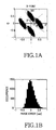
- Fig. 1A is a view illustrating a constellation in a conventional 3-sample algorithm (i.e., 3-point algorithm).
- Fig. 1B is a view illustrating a phase error distribution in a conventional 3-sample algorithm.
- Fig. 2A is a view illustrating a constellation in a conventional 4-sample algorithm (i.e., 4-point algorithm).
- Fig. 2B is a view illustrating a phase error distribution in a conventional 4-sample algorithm.
- Figs. 1A and 2A in case of considering an axis of 0° and an axis of 90° as reference lines, Fig. 1A using the 3-point algorithm shows that symbols ⁇ and ⁇ each have errors of almost 90° and the distribution of the errors is in a wide range. Fig. 2A using the 4-point algorithm shows that values of symbols ⁇ and ⁇ are much less than the symbols ⁇ and ⁇ .
- the 4-point algorithm reduces the error distribution much more than the 3-point algorithm does.
- a processor used for phase calculation may receive an excessive load during a phase calculation time.
- One aspect of the present invention is to provide a phase demodulation method for minimizing a phase error of a communication signal by calculating an accurate phase using a minimum number of sampling times and a minimum number of calculation times.
- a phase demodulation method for improving a phase demodulation process applicable to various kinds of phase demodulation algorithms by only changing a signal processing method.
- phase demodulator for performing the phase demodulation methods.
- a phase demodulation method for demodulating a phase-demodulated communication signal using a digital phase demodulation algorithm including the steps of: adding one sampling to the digital phase demodulation algorithm represented by an equation where k is the number of sampling times and C k is a complex constant; and, demodulating the phase-demodulated communication signal.
- the step of adding one sampling for a phase error minimization to the digital phase demodulation algorithm may be represented by the following equation: where, k is the number of sampling times, C k and d k are complex constants, and ⁇ - x indicates the one sampling added in the step.
- the phase error minimization may be determined by a value of ⁇ satisfying the following equation: where, k is the number of sampling times, C k and d k are complex constants, and ⁇ is a phase error.
- the present invention relates to a method for minimizing a phase error in the case where physical noises are propagated in phase spaces (i.e., I and Q spaces) of a signal in a step for determining a coefficient C k .
- phase spaces i.e., I and Q spaces
- sampled signals are affected by the Gaussian noise as shown in the following Equation 4.
- Equation 5 The above signals are propagated with a complex phasor S as shown in the following Equation 5.
- Errors of the complex phasor S can be represented as a magnitude error ⁇
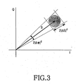
- Fig. 3 is a view illustrating a relationship between phase magnitude and phase deviation in the case where noise added to an original signal is propagated in a phase plane. Particularly, Fig. 3 shows that the noise propagated in the phase space spreads a complex phasor S so that a phase error occurs.
- the aforesaid magnitude error and phase error of the complex phasor can be represented by the following Equation 6.
- the phase error the Taylor expansion method is used on the assumption that the phase error is low, and a value corresponding to a linear term is further reflected in a calculation procedure.
- a constant C k for minimizing an error of the complex phasor can be calculated by the above Eq. 6.
- the magnitude error is of little importance in a phase modulation/demodulation method. It is necessary to minimize the phase error only.
- 2 ⁇ of the phase error ranges from a minimum value ⁇ 2 /
- Equation 7 the complex phasor S is represented by the following Equation 7.
- F k (x) can be represented as a characteristic polynomial having a solution value of e im ⁇ in case of m ⁇ 1.
- phase demodulation characteristic polynomial so that a phase error is reduced. If a solution is added to a characteristic polynomial, a degree of the characteristic polynomial increases and a value of K also increases in a way so that the number of sampling points (i.e., times) increases by one. If the number of sampling times increases, reduction of the phase error is reasonable. If a wrong phase demodulation algorithm is adopted even though the number of sampling times increases, the phase error may be excessively higher. However, a phase demodulation algorithm created in accordance with the present invention can minimize the phase error at all times.
- Equation 9 In addition, in order to minimize the phase error, the following Equation 9 should be satisfied.
- phase error can be minimized regardless of Gaussian noise added to communication signals.
- the present invention is described on the assumption that the phase error has a low value, more effective results can be obtained if the present invention is actually applied to a phase modulation/demodulation method for subdividing phase intervals.
- Fig. 4A is a view illustrating a constellation in a conventional 4-sample algorithm (i.e., 4-point algorithm) in accordance with a preferred embodiment of the present invention.
- Fig. 4b is a view illustrating a phase error distribution in a conventional 4-sample algorithm in accordance with a preferred embodiment of the present invention.
- the magnitudes of ⁇ and ⁇ are much less than ⁇ and ⁇ shown in Fig. 1A using the conventional 3-point algorithm and ⁇ and ⁇ shown in Fig. 2A using the conventional 4-point algorithm.
- Table 1 is provided to illustrate the relationship among three kinds of phase demodulation algorithms for performing a phase demodulation operation by sampling a phase of input signals at intervals of ⁇ /3 radians. In this case, all the algorithms are designed to calculate the phase by automatically removing DC components from the input signals.
- the signal used for such phase demodulation is represented by an equation of 0.1 + cos ( ⁇ ), and the Gaussian noise having a standard deviation of 0.1 is added to this signal.
- Table 1 illustrates a first conventional algorithm for performing a phase demodulation operation using three samplings (i.e.; 3-sample algorithm or 3-point algorithm), and a second conventional algorithm using four samplings (i.e., 4-sample algorithm or 4-point algorithm).
- Table 1 variables of a k and b k and maximum and minimum values of phase deviation can be recognized.
- one sampling is added to the 3-sample algorithm to create an algorithm (i.e., 4-sample algorithm) for minimizing a phase error so that variables of a k and b k and maximum and minimum values of phase deviations can also be recognized.
- the second conventional algorithm shown in the second column of Table 1 and the algorithm of the present invention shown in the third column of Table 1 perform four samplings, so that they can be directly compared with each other as shown in Table 1.
- the inventive algorithm shown in the third column calculates a phase more accurately than the second conventional algorithm shown in the second column.
- a phase demodulation method demodulates a phase-modulated communication signal by adding one sampling minimizing a phase error to an arbitrary digital phase demodulation algorithm, it minimizes the phase error generated when a noise is propagated in phase space during a demodulation time of the phase-modulated communication signal, using a minimum number of sampling times and a minimum number of calculation times.
- phase demodulation method according to the present invention is easily applied to various kinds of phase demodulation algorithms by only changing a signal processing method, thereby improving a phase demodulation process.
Landscapes
- Engineering & Computer Science (AREA)
- Computer Networks & Wireless Communication (AREA)
- Signal Processing (AREA)
- Digital Transmission Methods That Use Modulated Carrier Waves (AREA)
Abstract

Description
- The present invention relates generally to a phase demodulation method for demodulating a phase-modulated communication signal. More particularly, the present invention relates to a phase demodulation method and a phase demodulator for minimizing a phase error generated by noise.
- Typically, a phase modulation/demodulation method in a communication field simultaneously varies and transmits a phase of sinusoidal waves of a predetermined frequency at intervals of a predetermined phase. Several problems causing distortions of the sinusoidal waves are created in such a process. An example of this is when a communication signal is loaded on a carrier wave and interference with other signals occur, or noise is undesirably added to a desired signal, etc., thereby distorting the sinusoidal waves: If a signal having the distorted sinusoidal waves is received at a reception end, a frequency of the signal is adjusted down to an initial frequency and filtered to be proper to a signal bandwidth in such a way that the signal is demodulated to an original signal. Commonly, in case of describing physical characteristics of a modulation/demodulation process, the above steps are simplified as a procedure for adding an independent Gaussian noise to an original signal. Provided that the Gaussian noise is not considered, signal waves received at a reception end can be represented by the following Equation 1.

- In case of a digital phase demodulation, a demodulated signal is sampled at a more than twice an original signal frequency. In this case, in case of representing a sampling interval as a phase interval of δ, a k-th sampled value is represented by the following Equation 2.

- A method for demodulating values called I and Q signals from the above sampling signals is called a phase demodulation algorithm. Such phase demodulation algorithm can be represented by the following Equation 3.

- Characteristics of the phase demodulation algorithm are determined by a coefficient Ck used in a complex phasor S.
- Fig. 1A is a view illustrating a constellation in a conventional 3-sample algorithm (i.e., 3-point algorithm). Fig. 1B is a view illustrating a phase error distribution in a conventional 3-sample algorithm. Fig. 2A is a view illustrating a constellation in a conventional 4-sample algorithm (i.e., 4-point algorithm). Fig. 2B is a view illustrating a phase error distribution in a conventional 4-sample algorithm.
- Referring to Figs. 1A and 2A, in case of considering an axis of 0° and an axis of 90° as reference lines, Fig. 1A using the 3-point algorithm shows that symbols α and β each have errors of almost 90° and the distribution of the errors is in a wide range. Fig. 2A using the 4-point algorithm shows that values of symbols γ and δ are much less than the symbols α and β.
- In addition, as shown in Figs. 1B and 2B, the 4-point algorithm reduces the error distribution much more than the 3-point algorithm does.
- It is noted that the aforesaid digital phase demodulation algorithms more accurately calculate a signal phase in proportion to the number of sampling times, and is also resistant to noise.
- However, it is impossible to indefinitely increase the number of sampling times in case of a symbol rate of a very high value. Also, a processor used for phase calculation may receive an excessive load during a phase calculation time.
- Therefore, there is a need for an optimized algorithm for calculating an accurate phase using a minimum number of sampling times and a minimum number of calculation times.
- It is the object of the present invention to provide a phase demodulation method for minimizing a phase error generated when a noise is propagated in phase space during a demodulation period of a phase-modulated communication signal.
- This object is solved by the subject matters of the independent claims.
- Preferred embodiments are defined in the dependent claims.
- One aspect of the present invention is to provide a phase demodulation method for minimizing a phase error of a communication signal by calculating an accurate phase using a minimum number of sampling times and a minimum number of calculation times.
- In yet another aspect of the present invention, a phase demodulation method is provided for improving a phase demodulation process applicable to various kinds of phase demodulation algorithms by only changing a signal processing method.
- In yet a further aspect of the present invention, a phase demodulator is provided for performing the phase demodulation methods.
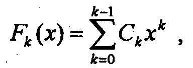
- In one embodiment of the present invention, a phase demodulation method for demodulating a phase-demodulated communication signal using a digital phase demodulation algorithm, including the steps of: adding one sampling to the digital phase demodulation algorithm represented by an equationwhere k is the number of sampling times and Ck is a complex constant; and, demodulating the phase-demodulated communication signal.
- In the embodiment, the step of adding one sampling for a phase error minimization to the digital phase demodulation algorithm may be represented by the following equation:where, k is the number of sampling times, Ck and dk are complex constants, and λ - x indicates the one sampling added in the step.

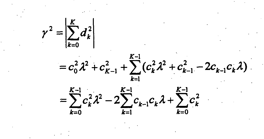
- In the embodiment, the phase error minimization may be determined by a value of λ satisfying the following equation:where, k is the number of sampling times, Ck and dk are complex constants, and γ is a phase error.
- Fig. 1A is a view illustrating a constellation in a conventional 3-sample algorithm (i.e., 3-point algorithm);
- Fig. 1B is a view illustrating a phase error distribution in a conventional 3-sample algorithm;
- Fig. 2A is a view illustrating a constellation in a conventional 4-sample algorithm (i.e., 4-point algorithm);
- Fig. 2B is a view illustrating a phase error distribution in a conventional 4-sample algorithm;
- Fig. 3 is a view illustrating a relationship between phase magnitude and phase deviation in the case where noise added to an original signal is propagated in a phase plane;
- Fig. 4A is a view illustrating a constellation in a conventional 4-sample algorithm (i.e., 4-point algorithm) in accordance with a preferred embodiment of the present invention; and,
- Fig. 4B is a view illustrating a phase error distribution in a conventional 4-sample algorithm in accordance with a preferred embodiment of the present invention.
-
- In accordance with the present invention, preferred embodiments of the present invention will be described in detail with reference to the annexed drawings. In the drawings, the same or similar elements are denoted by the same reference numerals even though they are depicted in different drawings. For the purposes of clarity and simplicity, a detailed description of known functions and configurations incorporated herein will be omitted as it may make the subject matter of the present invention unclear.
- The present invention relates to a method for minimizing a phase error in the case where physical noises are propagated in phase spaces (i.e., I and Q spaces) of a signal in a step for determining a coefficient Ck. In the case where Gaussian noise having an average value of 0 and a standard deviation of σ are added to signal waveforms during a communication step, sampled signals are affected by the Gaussian noise as shown in the following Equation 4.
- The above signals are propagated with a complex phasor S as shown in the following Equation 5.

- Errors of the complex phasor S can be represented as a magnitude error 〈|ΔS|2〉 and an angle error 〈|Δϕ|2〉 in phase space.
- Fig. 3 is a view illustrating a relationship between phase magnitude and phase deviation in the case where noise added to an original signal is propagated in a phase plane. Particularly, Fig. 3 shows that the noise propagated in the phase space spreads a complex phasor S so that a phase error occurs.
- The aforesaid magnitude error and phase error of the complex phasor can be represented by the following Equation 6. In case of the phase error, the Taylor expansion method is used on the assumption that the phase error is low, and a value corresponding to a linear term is further reflected in a calculation procedure.

- A constant Ck for minimizing an error of the complex phasor can be calculated by the above Eq. 6. The magnitude error is of little importance in a phase modulation/demodulation method. It is necessary to minimize the phase error only. Provided that a signal phase ϕ is contained in the phase error, a value 〈|Δϕ|2〉 of the phase error ranges from a minimum value σ2 / |S|2[ρ 2+γ2] to a maximum value σ2 / |S|2[ρ2-γ2] Therefore, in order to minimize the phase error value, only γ2 should be minimized.
- Therefore, in order to minimize the phase error in a phase demodulation algorithm for demodulating phase-modulated communication signals, a phase demodulation algorithm needs to demodulate an accurate phase, and the value of γ2 should be zero. In order to recognize a principle for enabling the phase demodulation algorithm to demodulate an accurate phase, the complex phasor S is represented by the following Equation 7.

- Considering that the complex phasor S should have a phase of ϕo, a value of Fk(eimδ) should be 0 in case of m≠1, or should be 1 in case of m=1. So, Fk(x) can be represented as a characteristic polynomial having a solution value of eimδ in case of m≠1. Herein, there is no problem in a phase demodulation step even though Fk(x) has another solution value. In case of using an arbitrary phase demodulation algorithm, i.e., in case of Fk(x) is fixed to a predetermined value, there is no problem even though a specific value of λ-x in case of λ≠eiδ is multiplied by the value of Fk(x).
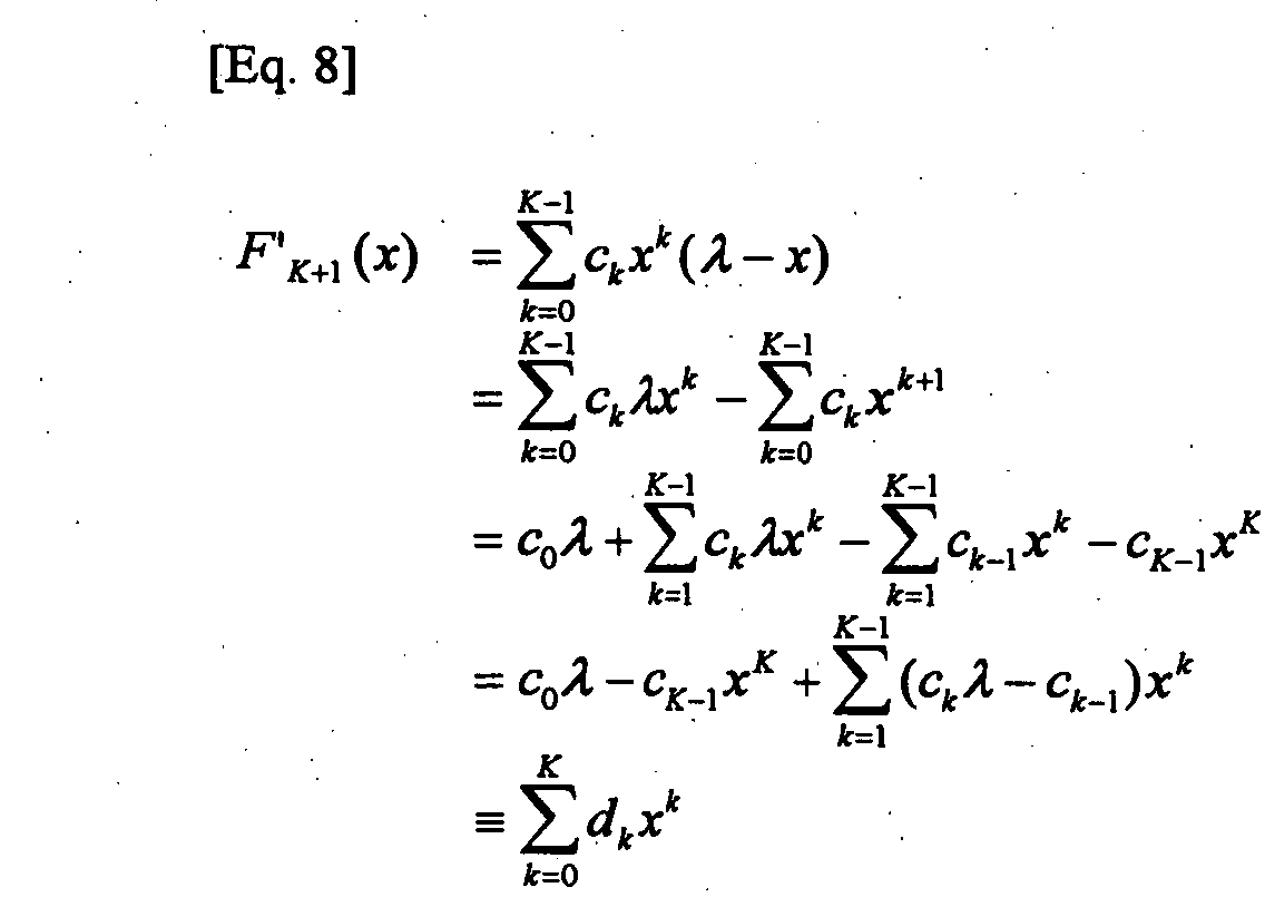
- Therefore, one arbitrary solution is added to an arbitrary phase demodulation characteristic polynomial so that a phase error is reduced. If a solution is added to a characteristic polynomial, a degree of the characteristic polynomial increases and a value of K also increases in a way so that the number of sampling points (i.e., times) increases by one. If the number of sampling times increases, reduction of the phase error is reasonable. If a wrong phase demodulation algorithm is adopted even though the number of sampling times increases, the phase error may be excessively higher. However, a phase demodulation algorithm created in accordance with the present invention can minimize the phase error at all times.
- First of all, one solution is added to an arbitrary phase demodulation characteristic polynomial as shown in the following Equation 8.
- In addition, in order to minimize the phase error, the following Equation 9 should be satisfied.
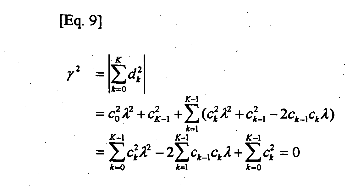
- In case of making a phase demodulation algorithm by calculating a value of λ from a quadratic equation related to λ shown in the above Eq. 9, a phase error can be minimized regardless of Gaussian noise added to communication signals. Although the present invention is described on the assumption that the phase error has a low value, more effective results can be obtained if the present invention is actually applied to a phase modulation/demodulation method for subdividing phase intervals.
- Fig. 4A is a view illustrating a constellation in a conventional 4-sample algorithm (i.e., 4-point algorithm) in accordance with a preferred embodiment of the present invention. Fig. 4b is a view illustrating a phase error distribution in a conventional 4-sample algorithm in accordance with a preferred embodiment of the present invention. As shown in Fig. 4A, the magnitudes of ε and are much less than α and β shown in Fig. 1A using the conventional 3-point algorithm and γ and δ shown in Fig. 2A using the conventional 4-point algorithm.
- The following Table 1 is provided to illustrate the relationship among three kinds of phase demodulation algorithms for performing a phase demodulation operation by sampling a phase of input signals at intervals of π/3 radians. In this case, all the algorithms are designed to calculate the phase by automatically removing DC components from the input signals.
3-sample algorithm 4-sample algorithm 3-sample algorithm + 1- sample algorithm 0, π/3, 2π/3 0, π/3, 2π/3, π 0, π/3, 2π/3, π ak {1, -1.5, 0.5} {1, -1, -1, 1} {1, -0.75, -1.198, 0.9478} bk {0, 0.8660, -0.8660} {0, 1.732, -1.732, 0} {0, 1.528, -1.209, -0.3188} Phase deviation[ rad] 0.02540(Maximum) 0.04678(Minimum) 0.01386(Maximum) 0.02023(Minimum) 0.01342 - The signal used for such phase demodulation is represented by an equation of 0.1 + cos (ϕ), and the Gaussian noise having a standard deviation of 0.1 is added to this signal.
- As shown in the above, Table 1 illustrates a first conventional algorithm for performing a phase demodulation operation using three samplings (i.e.; 3-sample algorithm or 3-point algorithm), and a second conventional algorithm using four samplings (i.e., 4-sample algorithm or 4-point algorithm). Based on the Table 1, variables of ak and bk and maximum and minimum values of phase deviation can be recognized. Further, in accordance with the present invention shown in the third column of Table 1, one sampling is added to the 3-sample algorithm to create an algorithm (i.e., 4-sample algorithm) for minimizing a phase error so that variables of ak and bk and maximum and minimum values of phase deviations can also be recognized.
- The second conventional algorithm shown in the second column of Table 1 and the algorithm of the present invention shown in the third column of Table 1 perform four samplings, so that they can be directly compared with each other as shown in Table 1. Apparently from Table 1, the inventive algorithm shown in the third column calculates a phase more accurately than the second conventional algorithm shown in the second column.
- As is apparent from the above description, since a phase demodulation method according to the present invention demodulates a phase-modulated communication signal by adding one sampling minimizing a phase error to an arbitrary digital phase demodulation algorithm, it minimizes the phase error generated when a noise is propagated in phase space during a demodulation time of the phase-modulated communication signal, using a minimum number of sampling times and a minimum number of calculation times.
- Furthermore, a phase demodulation method according to the present invention is easily applied to various kinds of phase demodulation algorithms by only changing a signal processing method, thereby improving a phase demodulation process.
- While the invention has been shown and described with reference to a preferred embodiment thereof, it will be understood by those skilled in the art that various changes in form and details may be made therein without departing from the scope of the invention as defined by the appended claims. Therefore, this invention is not to be unduly limited to the embodiment set forth herein, but to be defined by the appended claims and equivalents thereof.
Claims (4)
- A phase demodulation method for demodulating a phase-demodulated communication signal through a predetermined number of samplings using a digital phase demodulation algorithm, comprising the steps of:adding one sampling to the digital phase demodulation algorithm represented by an equationwhere k represents the number of sampling times and Ck represents a complex constant; and,
 demodulating the phase-demodulated communication signal.
 - The phase demodulation method according to claim 1, wherein the step of adding one sampling for a phase error minimization to the digital phase demodulation algorithm is represented by the following equation:where k represents the number of sampling times, Ck and dk are complex constants, and λ - x indicates the one sampling added.

- The phase demodulation method according to claim 2, wherein the phase error minimization is determined by a value of λ satisfying the following equation:where, k is the number of sampling times, Ck and dk are complex constants, and γ is a phase error.

- A phase demodulator adapted to perform the phase demodulation method according to one of claims 1 to 3.
Applications Claiming Priority (2)
| Application Number | Priority Date | Filing Date | Title |
|---|---|---|---|
| KR2002061478 | 2002-10-09 | ||
| KR1020020061478A KR100640432B1 (en) | 2002-10-09 | 2002-10-09 | Phase demodulation method to minimize phase error of communication signal |
Publications (2)
| Publication Number | Publication Date |
|---|---|
| EP1408663A2 true EP1408663A2 (en) | 2004-04-14 |
| EP1408663A3 EP1408663A3 (en) | 2006-12-06 |
Family
ID=32026130
Family Applications (1)
| Application Number | Title | Priority Date | Filing Date |
|---|---|---|---|
| EP03022850A Withdrawn EP1408663A3 (en) | 2002-10-09 | 2003-10-08 | Phase demodulation |
Country Status (5)
| Country | Link |
|---|---|
| US (1) | US6859094B2 (en) |
| EP (1) | EP1408663A3 (en) |
| JP (1) | JP3844756B2 (en) |
| KR (1) | KR100640432B1 (en) |
| CN (1) | CN100433744C (en) |
Cited By (1)
| Publication number | Priority date | Publication date | Assignee | Title |
|---|---|---|---|---|
| US7903769B2 (en) | 2005-12-12 | 2011-03-08 | Telefonaktiebolaget L M Ericsson (Publ) | Method and apparatus for phase-noise compensation in digital receivers |
Citations (1)
| Publication number | Priority date | Publication date | Assignee | Title |
|---|---|---|---|---|
| US6181751B1 (en) * | 1996-10-22 | 2001-01-30 | Nec Corporation | Multi-stage detection system in digital demodulator |
Family Cites Families (10)
| Publication number | Priority date | Publication date | Assignee | Title |
|---|---|---|---|---|
| JPS52123670A (en) * | 1976-04-09 | 1977-10-18 | Takeda Riken Ind Co Ltd | Digital frequency measuring device |
| US4112497A (en) * | 1977-03-29 | 1978-09-05 | Nasa | Digital demodulator-correlator |
| US4412302A (en) * | 1980-12-15 | 1983-10-25 | Rca Corporation | Digital phase demodulation and correlation |
| KR960009537B1 (en) * | 1993-12-21 | 1996-07-20 | Korea Electronics Telecomm | Circuit for detecting phase transformation |
| KR950026141A (en) * | 1994-02-08 | 1995-09-18 | 이헌조 | Symbol timing compensation device |
| JPH08139775A (en) * | 1994-11-14 | 1996-05-31 | Toyo Commun Equip Co Ltd | Digital demodulator |
| US5796780A (en) * | 1996-02-09 | 1998-08-18 | Ericsson Inc. | Coherent modulation of CPM signals |
| KR100200589B1 (en) * | 1996-06-12 | 1999-06-15 | 윤종용 | Digital reconstruction method and method of high resolution TV receiver |
| JP3918329B2 (en) * | 1998-11-24 | 2007-05-23 | 富士通株式会社 | Receiving apparatus and receiving method |
| KR100429981B1 (en) * | 2001-12-26 | 2004-05-03 | 엘지전자 주식회사 | Aqm error compensation apparatus and method |
-
2002
- 2002-10-09 KR KR1020020061478A patent/KR100640432B1/en not_active Expired - Fee Related
-
2003
- 2003-07-08 US US10/616,174 patent/US6859094B2/en not_active Expired - Lifetime
- 2003-08-21 CN CNB031543936A patent/CN100433744C/en not_active Expired - Fee Related
- 2003-10-06 JP JP2003346869A patent/JP3844756B2/en not_active Expired - Fee Related
- 2003-10-08 EP EP03022850A patent/EP1408663A3/en not_active Withdrawn
Patent Citations (1)
| Publication number | Priority date | Publication date | Assignee | Title |
|---|---|---|---|---|
| US6181751B1 (en) * | 1996-10-22 | 2001-01-30 | Nec Corporation | Multi-stage detection system in digital demodulator |
Cited By (1)
| Publication number | Priority date | Publication date | Assignee | Title |
|---|---|---|---|---|
| US7903769B2 (en) | 2005-12-12 | 2011-03-08 | Telefonaktiebolaget L M Ericsson (Publ) | Method and apparatus for phase-noise compensation in digital receivers |
Also Published As
| Publication number | Publication date |
|---|---|
| KR100640432B1 (en) | 2006-10-30 |
| US20040071230A1 (en) | 2004-04-15 |
| JP2004135332A (en) | 2004-04-30 |
| EP1408663A3 (en) | 2006-12-06 |
| CN100433744C (en) | 2008-11-12 |
| JP3844756B2 (en) | 2006-11-15 |
| US6859094B2 (en) | 2005-02-22 |
| KR20040032370A (en) | 2004-04-17 |
| CN1489352A (en) | 2004-04-14 |
Similar Documents
| Publication | Publication Date | Title |
|---|---|---|
| US6590860B1 (en) | Receiving device and signal receiving method | |
| US20040218520A1 (en) | OFDM receiver, semiconductor integrated circuit and OFDM method for receiving a signal | |
| JP4068228B2 (en) | Carrier control loop for digital transmission signal receiver | |
| US5115454A (en) | Method and apparatus for carrier synchronization and data detection | |
| US6415004B1 (en) | Phase detector, timing recovery device using the same, and a demodulator using the timing recovery device | |
| EP0736986B1 (en) | Data reception apparatus and method thereof which use reference data inserted into a transmission signal in order to estimate the transmission channel quality | |
| US7254189B1 (en) | Blind carrier offset detection for quadrature modulated digital communication systems | |
| US6442383B1 (en) | Demodulator and digital wireless communication receiver | |
| EP0788225B1 (en) | Frequency offset estimating circuit and AFC circuit using the same | |
| JP4402789B2 (en) | DC offset correction method and apparatus for direct conversion receiver | |
| US11601150B1 (en) | Demodulation for phase-noise mitigation in 5G and 6G | |
| JP7004618B2 (en) | Frequency estimator and tracking receiver | |
| JPH0654003A (en) | Signal series detection method | |
| JP2659060B2 (en) | Frequency error detection method | |
| CN116545824A (en) | Frequency offset estimation method, device and receiver | |
| EP1408663A2 (en) | Phase demodulation | |
| US5432819A (en) | DPSK communications with Doppler compensation | |
| EP0851640B1 (en) | Correction of DC and phase offsets in PSK receivers | |
| US6965654B1 (en) | Frequency offset quantity detecting apparatus | |
| JP4044022B2 (en) | MFSK reception system | |
| JP3350290B2 (en) | Receiver | |
| JP3498600B2 (en) | Carrier phase estimator and demodulator using carrier phase estimator | |
| JPH09246917A (en) | Frequency error estimation device | |
| CA2110032C (en) | Frequency error detecting device capable of correctly detecting a frequency error between a carrier frequency and a standard frequency | |
| US6639952B1 (en) | Demodulator synchronization loop lock-in detection circuit |
Legal Events
| Date | Code | Title | Description |
|---|---|---|---|
| PUAI | Public reference made under article 153(3) epc to a published international application that has entered the european phase |
Free format text: ORIGINAL CODE: 0009012 |
|
| 17P | Request for examination filed |
Effective date: 20031008 |
|
| AK | Designated contracting states |
Kind code of ref document: A2 Designated state(s): AT BE BG CH CY CZ DE DK EE ES FI FR GB GR HU IE IT LI LU MC NL PT RO SE SI SK TR |
|
| AX | Request for extension of the european patent |
Extension state: AL LT LV MK |
|
| PUAL | Search report despatched |
Free format text: ORIGINAL CODE: 0009013 |
|
| AK | Designated contracting states |
Kind code of ref document: A3 Designated state(s): AT BE BG CH CY CZ DE DK EE ES FI FR GB GR HU IE IT LI LU MC NL PT RO SE SI SK TR |
|
| AX | Request for extension of the european patent |
Extension state: AL LT LV MK |
|
| AKX | Designation fees paid |
Designated state(s): DE FR GB |
|
| 17Q | First examination report despatched |
Effective date: 20100623 |
|
| RAP1 | Party data changed (applicant data changed or rights of an application transferred) |
Owner name: SAMSUNG ELECTRONICS CO., LTD. |
|
| GRAP | Despatch of communication of intention to grant a patent |
Free format text: ORIGINAL CODE: EPIDOSNIGR1 |
|
| INTG | Intention to grant announced |
Effective date: 20170621 |
|
| STAA | Information on the status of an ep patent application or granted ep patent |
Free format text: STATUS: THE APPLICATION IS DEEMED TO BE WITHDRAWN |
|
| 18D | Application deemed to be withdrawn |
Effective date: 20171103 |