EP1408594A2 - DC ground fault detector and system-interconnected generation device using the DC ground fault detector - Google Patents
DC ground fault detector and system-interconnected generation device using the DC ground fault detector Download PDFInfo
- Publication number
- EP1408594A2 EP1408594A2 EP03022214A EP03022214A EP1408594A2 EP 1408594 A2 EP1408594 A2 EP 1408594A2 EP 03022214 A EP03022214 A EP 03022214A EP 03022214 A EP03022214 A EP 03022214A EP 1408594 A2 EP1408594 A2 EP 1408594A2
- Authority
- EP
- European Patent Office
- Prior art keywords
- ground fault
- temperature
- power
- zero
- operative
- Prior art date
- Legal status (The legal status is an assumption and is not a legal conclusion. Google has not performed a legal analysis and makes no representation as to the accuracy of the status listed.)
- Granted
Links
Images



Classifications
-
- H—ELECTRICITY
- H02—GENERATION; CONVERSION OR DISTRIBUTION OF ELECTRIC POWER
- H02J—ELECTRIC POWER NETWORKS; CIRCUIT ARRANGEMENTS OR SYSTEMS FOR SUPPLYING OR DISTRIBUTING ELECTRIC POWER; SYSTEMS FOR STORING ELECTRIC ENERGY
- H02J3/00—Circuit arrangements for AC mains or AC distribution networks
- H02J3/38—Arrangements for feeding a single network from two or more generators or sources in parallel; Arrangements for feeding already energised networks from additional generators or sources in parallel
-
- H—ELECTRICITY
- H02—GENERATION; CONVERSION OR DISTRIBUTION OF ELECTRIC POWER
- H02H—EMERGENCY PROTECTIVE CIRCUIT ARRANGEMENTS
- H02H3/00—Emergency protective circuit arrangements for automatic disconnection directly responsive to an undesired change from normal electric working condition with or without subsequent reconnection ; integrated protection
- H02H3/16—Emergency protective circuit arrangements for automatic disconnection directly responsive to an undesired change from normal electric working condition with or without subsequent reconnection ; integrated protection responsive to fault current to earth, frame or mass
-
- H—ELECTRICITY
- H02—GENERATION; CONVERSION OR DISTRIBUTION OF ELECTRIC POWER
- H02H—EMERGENCY PROTECTIVE CIRCUIT ARRANGEMENTS
- H02H7/00—Emergency protective circuit arrangements specially adapted for specific types of electric machines or apparatus or for sectionalised protection of cable or line systems, and effecting automatic switching in the event of an undesired change from normal working conditions
- H02H7/10—Emergency protective circuit arrangements specially adapted for specific types of electric machines or apparatus or for sectionalised protection of cable or line systems, and effecting automatic switching in the event of an undesired change from normal working conditions for converters; for rectifiers
- H02H7/12—Emergency protective circuit arrangements specially adapted for specific types of electric machines or apparatus or for sectionalised protection of cable or line systems, and effecting automatic switching in the event of an undesired change from normal working conditions for converters; for rectifiers for static converters or rectifiers
- H02H7/122—Emergency protective circuit arrangements specially adapted for specific types of electric machines or apparatus or for sectionalised protection of cable or line systems, and effecting automatic switching in the event of an undesired change from normal working conditions for converters; for rectifiers for static converters or rectifiers for inverters, i.e. DC/AC converters
- H02H7/1222—Emergency protective circuit arrangements specially adapted for specific types of electric machines or apparatus or for sectionalised protection of cable or line systems, and effecting automatic switching in the event of an undesired change from normal working conditions for converters; for rectifiers for static converters or rectifiers for inverters, i.e. DC/AC converters responsive to abnormalities in the input circuit, e.g. transients in the DC input
-
- H—ELECTRICITY
- H02—GENERATION; CONVERSION OR DISTRIBUTION OF ELECTRIC POWER
- H02J—ELECTRIC POWER NETWORKS; CIRCUIT ARRANGEMENTS OR SYSTEMS FOR SUPPLYING OR DISTRIBUTING ELECTRIC POWER; SYSTEMS FOR STORING ELECTRIC ENERGY
- H02J3/00—Circuit arrangements for AC mains or AC distribution networks
- H02J3/38—Arrangements for feeding a single network from two or more generators or sources in parallel; Arrangements for feeding already energised networks from additional generators or sources in parallel
- H02J3/381—Dispersed generators
-
- H—ELECTRICITY
- H02—GENERATION; CONVERSION OR DISTRIBUTION OF ELECTRIC POWER
- H02J—ELECTRIC POWER NETWORKS; CIRCUIT ARRANGEMENTS OR SYSTEMS FOR SUPPLYING OR DISTRIBUTING ELECTRIC POWER; SYSTEMS FOR STORING ELECTRIC ENERGY
- H02J2101/00—Supply or distribution of decentralised, dispersed or local electric power generation
- H02J2101/20—Dispersed power generation using renewable energy sources
- H02J2101/22—Solar energy
- H02J2101/24—Photovoltaics
-
- Y—GENERAL TAGGING OF NEW TECHNOLOGICAL DEVELOPMENTS; GENERAL TAGGING OF CROSS-SECTIONAL TECHNOLOGIES SPANNING OVER SEVERAL SECTIONS OF THE IPC; TECHNICAL SUBJECTS COVERED BY FORMER USPC CROSS-REFERENCE ART COLLECTIONS [XRACs] AND DIGESTS
- Y02—TECHNOLOGIES OR APPLICATIONS FOR MITIGATION OR ADAPTATION AGAINST CLIMATE CHANGE
- Y02E—REDUCTION OF GREENHOUSE GAS [GHG] EMISSIONS, RELATED TO ENERGY GENERATION, TRANSMISSION OR DISTRIBUTION
- Y02E10/00—Energy generation through renewable energy sources
- Y02E10/50—Photovoltaic [PV] energy
- Y02E10/56—Power conversion systems, e.g. maximum power point trackers
Definitions
- the present invention relates to a system-interconnected generation device, which includes a DC ground fault detector operative to detect a ground fault about DC power lines that are arranged to allow a DC current generated at a generation unit to flow therethrough, and which regeneratively supplies the power generated at the generation unit to a commercial power system.
- a recent widespread system-interconnected generation device self-consumes part of the power generated using sunlight as an energy source and regeneratively supplies extra power not self-consumed to a commercial power system.
- Such the system-interconnected generation device comprises a booster circuit operative to boost a voltage of DC power generated from a solar battery, and an inverter circuit operative to control the DC power to be converted into AC power with the same frequency as that of AC power in the commercial power system.
- the system-interconnected generation device may also comprise a current sensor located near DC power lines that are arranged to connect the solar battery to the system-interconnected generation device as disclosed in the patent publication 1 (JP-A-2001/275259).
- a ground fault is determined about the DC power lines based on a variation in the output from the current sensor, the solar battery is disconnected from the system-interconnected generation device to improve safety.
- the current sensor for DC ground fault detection may suffer a temperature drift.
- an expensive material such as a saturable reactor for a magnetic wound core, which causes a problem associated with the cost elevation.
- the present invention has an object to provide an inexpensive DC ground fault detector and a system-interconnected generation device that includes the DC ground fault detector.
- the present invention provides a DC ground fault detector, which comprises a zero-phase current transformer (ZCT) configured to receive a pair of DC power lines passing therethrough and operative to output a current difference between currents flowing in the DC power lines to determine a ground fault about the DC power lines based on the current difference and a predetermined reference value.
- the DC ground fault detector further comprises a temperature sensor operative to detect a temperature on the zero-phase current transformer (ZCT) or an ambient temperature in the vicinity of the zero-phase current transformer; and a temperature corrector operative to correct the current difference output from the zero-phase current transformer (ZCT) or the reference value based on the temperature detected at the temperature sensor.
- the present invention also provides a system-interconnected generation device, which comprises a booster circuit operative to boost a DC power supplied from a generation unit; an inverter circuit operative to convert the DC power boosted at the booster circuit into an AC power with a certain controlled frequency; a controller operative to control the booster circuit and the frequency to regeneratively supply the AC power to a commercial power system; and a DC ground fault detector configured to detect a ground fault about DC power lines arranged to supply DC power from the generation unit.
- the DC ground fault detector includes a zero-phase current transformer (ZCT) configured to receive a pair of DC power lines passing therethrough and operative to output a current difference between currents flowing in the DC power lines to determine a ground fault about the DC power lines based on the current difference and a predetermined reference value; a temperature sensor operative to detect a temperature on the zero-phase current transformer (ZCT) or an ambient temperature in the vicinity of the zero-phase current transformer; and a temperature corrector operative to correct the current difference output from the zero-phase current transformer (ZCT) or the reference value based on the temperature detected at the temperature sensor.
- ZCT zero-phase current transformer
- the generation unit may comprise a solar battery operative to receive sunlight to generate the DC power.
- Fig. 1 is a circuit diagram showing an embodiment of a system-interconnected generation device connected to a generation unit and a commercial power system.
- the generation unit may include a solar battery as well as a fuel cell and a commonly known generator.
- rectified DC power is employed.
- a system-interconnected generation device 10 is connected through terminals P and N to a solar battery 11.
- the system-interconnected generation device 10 is also connected (interconnected) through terminals R, O and T to the commercial power system 13 (shown as a single-phase three-wire system).
- the system-interconnected generation device 10 is operative to convert DC power, generated at the solar battery 11 when it is exposed to sunlight, into AC power with the same frequency as that of the commercial power system 13, which is regeneratively supplied to the commercial power system 13.
- the solar battery 11 has an array configuration (PV array) that consists of a plurality of solar battery cells.
- the system-interconnected generation device 10 mainly comprises a booster circuit 14, an inverter circuit 15, a low-pass filter 16, and a microcomputer 17 serving as a controller.
- a generated voltage sensor 33 detects a voltage of the DC power supplied from the solar battery 11 to the booster 14.
- a generated current sensor 34 similarly detects a current thereof.
- a boosted voltage sensor 18 detects a voltage of the DC power boosted at the booster 14.
- a first system voltage sensor 19 detects an AC voltage between the terminals R and O from the system-interconnected generation device.
- a second system voltage sensor 20 similarly detects an AC voltage between the terminals O and T.
- An inverter output current sensor 21 detects an AC current of the AC power output from the inverter 15.
- a temperature sensor 50 is arranged to detect a temperature on a zero-phase current transformer (ZCT) or an ambient temperature in the vicinity thereof.
- ZCT zero-phase current transformer
- the booster 14 receives the unstable DC power generated from the solar battery 11 (the generated power varies depending on environmental factors such as clear, cloudy, rainy, morning, day and night).
- the booster 14 boosts the DC power so as to have a higher voltage than the system voltage of the commercial power system 13.
- the booster 14 includes a smoothing capacitor 22, a choke coil 23, a switching circuit 24, a diode 25 and a capacitor 26.
- the smoothing capacitor 22 stabilizes the DC power supplied to the choke coil 23 and the switching circuit 24.
- the switching circuit 24 includes a switching element 27 and a diode 28.
- a power transistor, a power MOSFET or an IGBT may be suitable for the switching element 27.
- the current accumulated in the choke coil 23 boosts the anode side of the diode 25 to a high voltage in addition to the voltage on the smoothing capacitor 22.
- the current flows through the diode 25 into the capacitor 26 to elevate the terminal voltage across the capacitor 26 close to the high voltage. In this case, the diode 25 prevents the reverse flow of power from the capacitor 26.
- the switching element 27 is kept in ON-state for a certain time period (that is, ON-duty), which is adjustable to control the voltage placed across the capacitor 26 in the booster 14. If the system voltage in the commercial power system 13 is equal to AC 200V, it has a crest value (peak value) of ⁇ 280V. Therefore, it is required to boost the voltage at the booster 14 up to DC 280V or more to regeneratively supply the AC power to the commercial power system 13 from a system interconnection device 12. In practice, the voltage boosted at the booster 14 is set at a value higher than 280V by 20-30V in consideration of an on-resistance of a switching element 29 (later described) in the inverter 15 and a resistance of a reactor 31 in the current smoothing circuit 16.
- the inverter 15 includes four bridged switching elements 29 (to generate a single-phase AC; and six to generate a three-phase AC) each provided with a diode 30 (flywheel diode).
- the inverter 15 converts the DC power boosted at the booster 14 into a pseudo-sinusoidal AC power with the same frequency and the same or almost same phase as those of the commercial power system 13.
- the inverter 15 turns the switching elements 29 on/off to convert the DC power received from the booster 14 into a pulse-width-modulated (PWM) AC power.
- the waveform of the AC power (AC current, AC voltage) output from the inverter 15 can meet the AC voltage waveform of the system voltage in the commercial power system 13 when the time period of the switching element 29 in ON-state (ON-duty) is appropriately adjusted. Consequently, the phase and frequency of the AC power output from the inverter 15 can be substantially coincident with that of the system power in the commercial power system 13.
- the current smoothing circuit 16 includes a reactor 31 and a capacitor 32, as shown in Fig. 1, to smooth the current of the AC power converted by the inverter 15.
- the AC power smoothed by the current smoothing circuit 16 is regeneratively supplied to the commercial power system 13 through a noise filter 36, a system release contactor 37 and a protective relay 38.
- the release contactor 37 is operative under the control of the microcomputer 7 to connect/disconnect the system-interconnected generation device 10 with the commercial power system 13. As described later in detail, the microcomputer 7 provides an actuation signal to the release contactor 37 to disconnect the system-interconnected generation device 10 from the commercial power system 13 for terminating the running of the system-interconnected generation device 10; and to connect the system-interconnected generation device 10 with the commercial power system 13 for beginning the running of the system-interconnected generation device 10.
- the generated voltage sensor 33 includes an isolation amplifier, for example, to measure the voltage of the DC power generated at the solar battery 11 and supplied to the booster 14 and provide the measured value to the microcomputer 17.
- the generated current sensor 34 includes a current transformer, for example, to measure the current of the DC power generated at the solar battery 11 and supplied to the booster 14 and provide the measured value to the microcomputer 17.
- the boosted voltage sensor 18 includes an isolation amplifier, for example, to measure the boosted voltage output from the booster 14 and provide the measured value to the microcomputer 17.
- the first system voltage sensor 19 and the second system voltage sensor 20 have transformers to measure the system voltages of the system power in the commercial power system 13 and provide the measured values to the microcomputer 17.
- the inverter output current sensor 21 includes a current transformer, for example, to measure the AC current converted at the inverter 15 and provide the measured value to the microcomputer 17.
- the temperature sensor 50 is operative to measure a temperature on the zero-phase current transformer (ZCT) 41 or an ambient temperature in the vicinity thereof and provide the measured value to the microcomputer 17.
- ZCT zero-phase current transformer
- Fig. 2 is a block diagram of the DC ground fault detector 40 briefly configured.
- the microcomputer 17, or a part of the DC ground fault detector 40 is provided with a PWM (Pulse Width Modulation) port 47 configured to provide an ON/OFF signal; a first A/D port 48 configured to receive an analog voltage; a second A/D port 49 configured to receive an analog voltage, or the measured value from the temperature sensor 50; an I/O interface 51; an oscillator and frequency divider 52; a MPU (Central Processing Unit) 53; a ROM (Read Only Memory) 54; a RAM (Random Access Memory) 55; and a bus (signal lines) 56.
- PWM Pulse Width Modulation
- the I/O interface 51 controls signal (data) communications among the PWM port 47, the second A/D port 49, the MPU, and the oscillator and frequency divider.
- the oscillator and frequency divider 52 creates a reference oscillation signal (reference clock signal) based on oscillations of a quartz vibrator 46 and, based on the reference oscillation signal, a pulse signal train with a certain frequency, ON-duty (for example, 50%) and voltage.
- This pulse signal train is output to the zero-phase current transformer (ZCT) 41 as an exciting pulse signal through the I/O interface 51, the PWM port 47 and an exciting amplifier (buffer amplifier) 42.
- ZCT zero-phase current transformer
- An example of the exciting pulse signal output has a pulse waveform with a voltage of +2.5V ⁇ 2.5V.
- the MPU 53 totally controls the microcomputer 17 in accordance with a control program stored in the ROM 54.
- the ROM 54 previously stores control data containing the control program.
- the RAM 55 is employed to store various data temporarily.
- the bus 56 connects the I/O interface 51, the MPU 53, the ROM 54 and the RAM 55 to each other.
- the microcomputer 17 receives the measured value from the generated voltage sensor 33 and the measured value from the generated current sensor 34 and determines the power generated at the solar battery 11 through computation.
- the microcomputer 17 turns on the release contactor (normally-open contact) 37 to close the contact. Consequently, the system-interconnected generation device 10 is connected with the commercial power system 13 to begin the running of the system-interconnected generation device 10.
- the AC power supplied from the system-interconnected generation device 10 to the commercial power system 13 is required to have a higher crest value (peak value) than a total of crest values of the AC power measured at the first system voltage sensor 19 and the AC power measured at the second system voltage sensor 20. Accordingly, the microcomputer 17 adjusts the DC voltage measured at the boosted voltage sensor 18 so as to exhibit a higher value by 20-30V than the total of the crest values. This adjustment can be executed in the microcomputer 17 by adjusting the ON-duty of the ON/OFF signal given to the switching element 27 for obtaining a pseudo-sinusoidal wave with a predetermined pattern to be output to the booster 14.
- the microcomputer 17 determines zero-cross points in the waveforms (sinusoidal waves) of the system voltage detected by the first system voltage sensor 19 and the second system voltage sensor 20 to establish synchronization with the ON/OFF signal given to the switching element 27 for obtaining the pseudo-sinusoidal wave with the predetermined pattern.
- the microcomputer 17 controls the booster 14 and the inverter 15, the substantially same AC power as the AC power in the commercial power system 13 is supplied from the system-interconnected generation device 10 to the commercial power system 13.
- the system-interconnected generation device 10 includes two DC lines 39A and 39B arranged to connect the solar battery 11 with the booster 14. Through the DC lines 39A and 39B, a DC current flows from the solar battery 11 to the booster 14.
- the zero-phase current transformer (ZCT) 41 of the DC ground fault detector 40 is located around the two DC lines 39A and 39B, or target conductive lines to be measured.
- the DC ground fault detector 40 is described below.
- the DC ground fault detector 40 includes the zero-phase current transformer (ZCT) 41, the exciting amplifier 42, a voltage doubler rectifier 43, and the microcomputer 17. It detects a DC ground fault about the system-interconnected generation device 10 at the side close to the solar battery 11.
- ZCT zero-phase current transformer
- the zero-phase current transformer (ZCT) 41 includes a detecting core 44 configured to receive the two DC lines 39 passing therethrough.
- This ZCT has a wound core composed of an inexpensive magnetic substance such as permalloy.
- the detecting core (detecting magnetic substance) 44 in the ZCT is housed in a housing 45.
- an exciting pulse signal output from the PWM port 47 of the microcomputer 17 is fed to the winding of the zero-phase current transformer (ZCT) 41 to excite the detecting core 44.
- ZCT zero-phase current transformer
- the detecting core 44 kept in an excited state measures a difference (definite difference) between currents flowing in the two DC lines 39A and 39B and provides an output current (AC) in accordance with the current difference to the voltage doubler rectifier 43.
- the voltage doubler rectifier 43 rectifies the output current (AC) provided from the detecting core 44 of the zero-phase current transformer (ZCT) 41 and converts the rectified DC voltage into a double or more voltage, which is provided to the first A/D port 48 (A/D: Analog to Digital) of the microcomputer 17.
- the microcomputer 17 detects if a DC ground fault occurs about the DC lines 39A, 39B based on the magnitude of the voltage applied to the first A/D port 48.
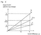
- Fig. 3 illustrates a relation of the current difference between currents flowing in the DC lines 39A and 39B to the output current from the detecting core 44 ( ⁇ the input voltage of the first A/D port 48).
- an ambient temperature in the vicinity of the detecting core 44 is assumed equal to a reference temperature Tref.
- I0 for example, 100 mA
- the MPU 53 in the microcomputer 17 determines that a ground fault occurs about the DC lines 39A and 39B, and detects a DC ground fault.
- the MPU 53 in the microcomputer 17 can not detect any DC ground fault in spite of an actual occurrence of the DC ground fault.
- the MPU 53 in the microcomputer 17 can detect a DC ground fault. In this case, however, the current I1 output from the detecting core 44 exceeds Iref even within a range of the current difference ⁇ I between I02 and I0. In the range of the current difference ⁇ I, the MPU 53 in the microcomputer 17 may detect a DC ground fault even though no DC ground fault occurs actually.
- the MPU 53 corrects the voltage input to the first A/D port 48 through a temperature corrective computation.
- the voltage input to the first A/D port 48 is converted into a voltage at the reference temperature Tref.
- Fig. 4 is a flowchart of brief processes in the DC ground fault detector 40.
- the MPU 53 receives the voltage input to the first A/D port 48 originated from the detecting core 44 and processed in the voltage doubler rectifier 43 to measure a current difference (Step S1).
- the MPU 53 then receives the voltage input to the second A/D port 49 from the temperature sensor 50 via the I/O interface 51 to measure an actual temperature Tm in the vicinity of the detecting core 44 (Step S2).
- the MPU 53 refers the ROM 54 next and, based on the temperature Tm measured at Step S2, corrects the voltage Vm input to the first A/D port 48 into a voltage at the reference temperature Tref to obtain a corrected voltage Vmc through a temperature corrective computation (Step S3).
- the MPU 53 determines if the corrected voltage Vmc is above the reference voltage Vref to determine if a ground fault is detected (Step S4).
- Step S4 if the corrected voltage Vmc is below the reference voltage Vref (Step S4: No), the MPU 53 determines that no ground fault is detected. In this case, the MPU 53 terminates the process of DC ground fault detection at that timing.
- Step S4 if the corrected voltage Vmc is above the reference voltage Vref (Step S4: Yes), the MPU 53 determines that a ground fault is detected. In this case, the MPU 53 performs processes after the ground fault detection such as disconnection of the current circuit and notification to the user (with an alarm output and an alert lamp turned-on), and terminates the process of DC ground fault detection.
- an inexpensive ZCT zero-phase current transformer
- ZCT zero-phase current transformer
- the zero-phase current transformer (ZCT) 41 can be configured with a low cost.
- detection of ground faults using the zero-phase current transformer (ZCT) 41 can ensure a high safety for the system-interconnected generation device 10.
- the temperature in the vicinity of the detecting core 44 is measured, and the temperature corrective computation is executed to reduce the influence from the temperature dependency of the current sensor 41. Therefore, accurate detection of ground faults can be achieved without addition of a temperature correcting circuit and selective use of a zero-phase current transformer (ZCT) with a smaller temperature drift.
- ZCT zero-phase current transformer
- the present invention has been described based on the above embodiment, though it is not limited in the embodiment.
- the reference voltage Vref may be corrected in the microcomputer 17 based on the measured value from the temperature sensor 50.
- the generation unit is exemplified as the solar battery 11, and the system-interconnected generation device is described for solar-electric power generation.
- Other generation units such as a wind-force power generator may be employed to regeneratively supply generated power to the commercial power system.
- the DC ground fault detector 40 is described as applied to the solar-electric power generation though it may also be applied particularly to a fuel cell for generating a high voltage.
Landscapes
- Engineering & Computer Science (AREA)
- Power Engineering (AREA)
- Inverter Devices (AREA)
- Supply And Distribution Of Alternating Current (AREA)
- Emergency Protection Circuit Devices (AREA)
- Testing Of Short-Circuits, Discontinuities, Leakage, Or Incorrect Line Connections (AREA)
- Measuring Instrument Details And Bridges, And Automatic Balancing Devices (AREA)
Abstract
Description
I1 < Iref
Accordingly,
V1 < Vref
In this case, the
I1 > Iref
Accordingly,
V1 > Vref
Thus, the
Claims (3)
- A DC ground fault detector (40), which comprises a zero-phase current transformer (ZCT) (41) configured to receive a pair of DC power lines (39A, 39B) passing therethrough and operative to output a current difference between currents flowing in said DC power lines to determine a ground fault about said DC power lines based on said current difference and a predetermined reference value, characterized in that said DC ground fault detector (40) further comprises a temperature sensor (50) operative to detect a temperature on said zero-phase current transformer (ZCT) or an ambient temperature in the vicinity of said zero-phase current transformer; and a temperature corrector (17) operative to correct said current difference output from said zero-phase current transformer (ZCT) or said reference value based on said temperature detected at said temperature sensor.
- A system-interconnected generation device (10), which comprises a booster circuit (14) operative to boost a DC power supplied from a generation unit (11); an inverter circuit (15) operative to convert said DC power boosted at said booster circuit into an AC power with a certain controlled frequency; a controller (17) operative to control said booster circuit and said frequency to regeneratively supply said AC power to a commercial power system (13); and a DC ground fault detector (40) configured to detect a ground fault about DC power lines arranged to supply DC power from said generation unit, characterized in that said DC ground fault detector (40) includes a zero-phase current transformer (ZCT) (41) configured to receive a pair of DC power lines (39A, 39B) passing therethrough and operative to output a current difference between currents flowing in said DC power lines to determine a ground fault about said DC power lines based on said current difference and a predetermined reference value; a temperature sensor (50) operative to detect a temperature on said zero-phase current transformer (ZCT) or an ambient temperature in the vicinity of said zero-phase current transformer; and a temperature corrector (17) operative to correct said current difference output from said zero-phase current transformer (ZCT) or said reference value based on said temperature detected at said temperature sensor.
- The system-interconnected generation device according to claim 2, characterized in that said generation unit (11) comprises a solar battery operative to receive sunlight to generate said DC power.
Applications Claiming Priority (4)
| Application Number | Priority Date | Filing Date | Title |
|---|---|---|---|
| JP2002297190 | 2002-10-10 | ||
| JP2002297190 | 2002-10-10 | ||
| JP2003305875A JP2004153991A (en) | 2002-10-10 | 2003-08-29 | DC ground fault detecting device, and grid-connected power generation device using the DC ground fault detecting device |
| JP2003305875 | 2003-08-29 |
Publications (3)
| Publication Number | Publication Date |
|---|---|
| EP1408594A2 true EP1408594A2 (en) | 2004-04-14 |
| EP1408594A3 EP1408594A3 (en) | 2006-09-20 |
| EP1408594B1 EP1408594B1 (en) | 2013-05-08 |
Family
ID=32032954
Family Applications (1)
| Application Number | Title | Priority Date | Filing Date |
|---|---|---|---|
| EP03022214.5A Expired - Lifetime EP1408594B1 (en) | 2002-10-10 | 2003-09-30 | DC ground fault detector and system-interconnected generation device using the DC ground fault detector |
Country Status (5)
| Country | Link |
|---|---|
| EP (1) | EP1408594B1 (en) |
| JP (1) | JP2004153991A (en) |
| KR (1) | KR100548086B1 (en) |
| CN (1) | CN1241028C (en) |
| TW (1) | TWI227957B (en) |
Cited By (8)
| Publication number | Priority date | Publication date | Assignee | Title |
|---|---|---|---|---|
| WO2007031357A3 (en) * | 2005-09-14 | 2007-10-11 | Siemens Akteingesellschaft Oes | Decentralized power supply device and method |
| WO2007115893A1 (en) * | 2006-04-07 | 2007-10-18 | Siemens Aktiengesellschaft | Space-saving inverter with reduced switching losses and increased life |
| EP1933156A4 (en) * | 2006-08-31 | 2011-03-02 | Mitsubishi Electric Corp | DEVICE FOR DETECTING ZERO CURRENT |
| US8860430B2 (en) | 2009-06-22 | 2014-10-14 | Jx Nippon Oil & Energy Corporation | Insulation resistance measurement device and insulation resistance measurement method |
| DE102013104629A1 (en) * | 2013-05-06 | 2014-11-06 | Refusol Gmbh | Energy generating device with functionally reliable potential separation |
| EP2741094A4 (en) * | 2011-08-01 | 2015-04-01 | Jx Nippon Oil & Energy Corp | EARTH FAULT DETECTION DEVICE, EARTH FAULT DETECTION METHOD, SOLAR ENERGY SYSTEM, AND EARTH FAULT DETECTION PROGRAM |
| GB2519342A (en) * | 2013-10-18 | 2015-04-22 | Heber Ltd | Detection of circuit integrity |
| CN107402340A (en) * | 2017-07-28 | 2017-11-28 | 南京南瑞继保电气有限公司 | A kind of single-phase grounded malfunction in grounded system of low current method of discrimination based on energy model |
Families Citing this family (13)
| Publication number | Priority date | Publication date | Assignee | Title |
|---|---|---|---|---|
| KR100618569B1 (en) * | 2004-10-21 | 2006-08-31 | 엘에스산전 주식회사 | Electronic power measuring device and method with temperature compensation function |
| CN101359029B (en) * | 2008-09-23 | 2010-06-02 | 东北电力大学 | Single-bus DC ground fault online automatic monitoring device |
| TWI420772B (en) * | 2010-04-06 | 2013-12-21 | Szu Lin Liu | Wind-powered output power regulating circuit |
| JP5835692B2 (en) * | 2011-11-30 | 2015-12-24 | 株式会社東芝 | Vehicle drive control device |
| CN105182220A (en) * | 2015-09-15 | 2015-12-23 | 安徽佑赛科技有限公司 | Three phase full bridge inverter power circuit test system and method |
| CN106772191A (en) * | 2016-11-28 | 2017-05-31 | 株洲中车时代电气股份有限公司 | A kind of method for improving current transformer control accuracy, device and current transformer |
| JP6319929B1 (en) * | 2017-03-24 | 2018-05-09 | 竹内マネージメント株式会社 | DC ground fault detection device, solar power generation system, and program |
| CN107478929A (en) * | 2017-08-03 | 2017-12-15 | 国网四川省电力公司电力科学研究院 | A kind of multifunctional mobile earthing or grounding means test system |
| JP6851002B2 (en) * | 2018-01-25 | 2021-03-31 | パナソニックIpマネジメント株式会社 | Power supply circuit and fuel cell power generation system |
| CN110032236B (en) * | 2019-04-30 | 2024-01-23 | 成都新欣神风电子科技有限公司 | DC sensor circuit with arbitrary bias voltage output |
| EP3893346A1 (en) | 2020-04-09 | 2021-10-13 | HS Elektronik Systeme GmbH | Electric safety circuit |
| KR102794719B1 (en) * | 2024-08-29 | 2025-04-15 | 주식회사 루텍 | Measurement Device Having Detachable Thermometer Module |
| CN120802129B (en) * | 2025-09-16 | 2026-02-06 | 国网浙江省电力有限公司永嘉县供电公司 | Line testing method, apparatus, equipment and medium based on DC signal testing |
Family Cites Families (4)
| Publication number | Priority date | Publication date | Assignee | Title |
|---|---|---|---|---|
| JPH01113674A (en) * | 1987-10-28 | 1989-05-02 | Asahi Chem Ind Co Ltd | Current detector |
| JPH11122819A (en) * | 1997-10-20 | 1999-04-30 | Fuji Electric Co Ltd | DC ground fault detector |
| JP2002233045A (en) * | 2001-02-02 | 2002-08-16 | Canon Inc | Apparatus and method for ground fault detection in a photovoltaic power system |
| JP2003262655A (en) * | 2002-03-08 | 2003-09-19 | Fuji Electric Co Ltd | DC leakage detector |
-
2003
- 2003-08-29 JP JP2003305875A patent/JP2004153991A/en active Pending
- 2003-09-29 TW TW092126819A patent/TWI227957B/en not_active IP Right Cessation
- 2003-09-29 CN CNB031248829A patent/CN1241028C/en not_active Expired - Lifetime
- 2003-09-29 KR KR1020030067480A patent/KR100548086B1/en not_active Expired - Fee Related
- 2003-09-30 EP EP03022214.5A patent/EP1408594B1/en not_active Expired - Lifetime
Cited By (8)
| Publication number | Priority date | Publication date | Assignee | Title |
|---|---|---|---|---|
| WO2007031357A3 (en) * | 2005-09-14 | 2007-10-11 | Siemens Akteingesellschaft Oes | Decentralized power supply device and method |
| WO2007115893A1 (en) * | 2006-04-07 | 2007-10-18 | Siemens Aktiengesellschaft | Space-saving inverter with reduced switching losses and increased life |
| EP1933156A4 (en) * | 2006-08-31 | 2011-03-02 | Mitsubishi Electric Corp | DEVICE FOR DETECTING ZERO CURRENT |
| US8860430B2 (en) | 2009-06-22 | 2014-10-14 | Jx Nippon Oil & Energy Corporation | Insulation resistance measurement device and insulation resistance measurement method |
| EP2741094A4 (en) * | 2011-08-01 | 2015-04-01 | Jx Nippon Oil & Energy Corp | EARTH FAULT DETECTION DEVICE, EARTH FAULT DETECTION METHOD, SOLAR ENERGY SYSTEM, AND EARTH FAULT DETECTION PROGRAM |
| DE102013104629A1 (en) * | 2013-05-06 | 2014-11-06 | Refusol Gmbh | Energy generating device with functionally reliable potential separation |
| GB2519342A (en) * | 2013-10-18 | 2015-04-22 | Heber Ltd | Detection of circuit integrity |
| CN107402340A (en) * | 2017-07-28 | 2017-11-28 | 南京南瑞继保电气有限公司 | A kind of single-phase grounded malfunction in grounded system of low current method of discrimination based on energy model |
Also Published As
| Publication number | Publication date |
|---|---|
| CN1497259A (en) | 2004-05-19 |
| CN1241028C (en) | 2006-02-08 |
| TWI227957B (en) | 2005-02-11 |
| JP2004153991A (en) | 2004-05-27 |
| EP1408594B1 (en) | 2013-05-08 |
| EP1408594A3 (en) | 2006-09-20 |
| TW200409432A (en) | 2004-06-01 |
| KR100548086B1 (en) | 2006-02-02 |
| KR20040032750A (en) | 2004-04-17 |
Similar Documents
| Publication | Publication Date | Title |
|---|---|---|
| EP1408594B1 (en) | DC ground fault detector and system-interconnected generation device using the DC ground fault detector | |
| EP1271742B1 (en) | System interconnection electric power generator | |
| KR100809443B1 (en) | Controller of Single Phase Power Converter for Solar Power System | |
| US9065323B2 (en) | Systems and methods for detecting islanding conditions in grid-tied inverters | |
| JP6337468B2 (en) | Ground fault detection device | |
| JP6248729B2 (en) | Control device, power conversion device, power supply system, program, and control method | |
| JPS58182726A (en) | Optimal operating point automatic setting method and device for DC power supply | |
| JP2013042627A (en) | Dc power supply control device and dc power supply control method | |
| US20170317503A1 (en) | Power storage control apparatus, direct-current power system, and controlling method thereof | |
| JP2016131441A (en) | Isolated operation detector, controller, power conditioner, power supply system, and isolated operation detection method | |
| US8803497B2 (en) | Current detector of inductive load | |
| JP2018207763A (en) | Power converter and reactor abnormality detection method provided in power converter | |
| CN121752911A (en) | Detecting grid impedance in a power grid | |
| US5631542A (en) | Method for controlling the strength of a charging current | |
| JP2005312158A (en) | Power converter, control method therefor, and solar power generator | |
| US6879061B2 (en) | Current adjusting apparatus and current adjusting method | |
| JP2003018740A (en) | DC ground fault detector and grid-connected power generator | |
| JP2001037252A (en) | Sine wave generation method for power factor correction control | |
| JP2000184739A (en) | Power converter control method | |
| JP2004032914A (en) | Grid-connected inverter and grid-connected system using the same | |
| JP2000217256A (en) | Automatic voltage regulator | |
| JP2852351B2 (en) | Power converter for solar cells | |
| JP2000023368A (en) | Solar power system | |
| JPH1014113A (en) | Operation method of grid-connected inverter | |
| CN209525397U (en) | A phase loss detection device for n-phase power supply |
Legal Events
| Date | Code | Title | Description |
|---|---|---|---|
| PUAI | Public reference made under article 153(3) epc to a published international application that has entered the european phase |
Free format text: ORIGINAL CODE: 0009012 |
|
| 17P | Request for examination filed |
Effective date: 20040217 |
|
| AK | Designated contracting states |
Kind code of ref document: A2 Designated state(s): AT BE BG CH CY CZ DE DK EE ES FI FR GB GR HU IE IT LI LU MC NL PT RO SE SI SK TR |
|
| AX | Request for extension of the european patent |
Extension state: AL LT LV MK |
|
| PUAL | Search report despatched |
Free format text: ORIGINAL CODE: 0009013 |
|
| AK | Designated contracting states |
Kind code of ref document: A3 Designated state(s): AT BE BG CH CY CZ DE DK EE ES FI FR GB GR HU IE IT LI LU MC NL PT RO SE SI SK TR |
|
| AX | Request for extension of the european patent |
Extension state: AL LT LV MK |
|
| RIC1 | Information provided on ipc code assigned before grant |
Ipc: H02H 3/16 20060101ALI20060811BHEP Ipc: G01R 31/02 20060101ALI20060811BHEP Ipc: H02H 7/122 20060101AFI20040120BHEP |
|
| AKX | Designation fees paid |
Designated state(s): DE FR GB IT NL |
|
| 17Q | First examination report despatched |
Effective date: 20071017 |
|
| GRAP | Despatch of communication of intention to grant a patent |
Free format text: ORIGINAL CODE: EPIDOSNIGR1 |
|
| GRAS | Grant fee paid |
Free format text: ORIGINAL CODE: EPIDOSNIGR3 |
|
| GRAA | (expected) grant |
Free format text: ORIGINAL CODE: 0009210 |
|
| RAP1 | Party data changed (applicant data changed or rights of an application transferred) |
Owner name: SANYO ELECTRIC CO. LTD |
|
| AK | Designated contracting states |
Kind code of ref document: B1 Designated state(s): DE FR GB IT NL |
|
| REG | Reference to a national code |
Ref country code: GB Ref legal event code: FG4D |
|
| REG | Reference to a national code |
Ref country code: DE Ref legal event code: R096 Ref document number: 60343976 Country of ref document: DE Effective date: 20130704 |
|
| REG | Reference to a national code |
Ref country code: NL Ref legal event code: VDEP Effective date: 20130508 |
|
| PG25 | Lapsed in a contracting state [announced via postgrant information from national office to epo] |
Ref country code: NL Free format text: LAPSE BECAUSE OF FAILURE TO SUBMIT A TRANSLATION OF THE DESCRIPTION OR TO PAY THE FEE WITHIN THE PRESCRIBED TIME-LIMIT Effective date: 20130508 |
|
| PLBE | No opposition filed within time limit |
Free format text: ORIGINAL CODE: 0009261 |
|
| STAA | Information on the status of an ep patent application or granted ep patent |
Free format text: STATUS: NO OPPOSITION FILED WITHIN TIME LIMIT |
|
| 26N | No opposition filed |
Effective date: 20140211 |
|
| REG | Reference to a national code |
Ref country code: DE Ref legal event code: R097 Ref document number: 60343976 Country of ref document: DE Effective date: 20140211 |
|
| GBPC | Gb: european patent ceased through non-payment of renewal fee |
Effective date: 20130930 |
|
| REG | Reference to a national code |
Ref country code: FR Ref legal event code: ST Effective date: 20140530 |
|
| PG25 | Lapsed in a contracting state [announced via postgrant information from national office to epo] |
Ref country code: GB Free format text: LAPSE BECAUSE OF NON-PAYMENT OF DUE FEES Effective date: 20130930 |
|
| PG25 | Lapsed in a contracting state [announced via postgrant information from national office to epo] |
Ref country code: FR Free format text: LAPSE BECAUSE OF NON-PAYMENT OF DUE FEES Effective date: 20130930 |
|
| PGFP | Annual fee paid to national office [announced via postgrant information from national office to epo] |
Ref country code: IT Payment date: 20150925 Year of fee payment: 13 |
|
| PG25 | Lapsed in a contracting state [announced via postgrant information from national office to epo] |
Ref country code: IT Free format text: LAPSE BECAUSE OF NON-PAYMENT OF DUE FEES Effective date: 20160930 |
|
| PGFP | Annual fee paid to national office [announced via postgrant information from national office to epo] |
Ref country code: DE Payment date: 20170927 Year of fee payment: 15 |
|
| REG | Reference to a national code |
Ref country code: DE Ref legal event code: R119 Ref document number: 60343976 Country of ref document: DE |
|
| PG25 | Lapsed in a contracting state [announced via postgrant information from national office to epo] |
Ref country code: DE Free format text: LAPSE BECAUSE OF NON-PAYMENT OF DUE FEES Effective date: 20190402 |