EP1407918B1 - Electric vehicle - Google Patents
Electric vehicle Download PDFInfo
- Publication number
- EP1407918B1 EP1407918B1 EP03023130A EP03023130A EP1407918B1 EP 1407918 B1 EP1407918 B1 EP 1407918B1 EP 03023130 A EP03023130 A EP 03023130A EP 03023130 A EP03023130 A EP 03023130A EP 1407918 B1 EP1407918 B1 EP 1407918B1
- Authority
- EP
- European Patent Office
- Prior art keywords
- controller
- power source
- vtc
- bmc
- battery
- Prior art date
- Legal status (The legal status is an assumption and is not a legal conclusion. Google has not performed a legal analysis and makes no representation as to the accuracy of the status listed.)
- Expired - Fee Related
Links
- 238000004891 communication Methods 0.000 claims description 115
- 230000004913 activation Effects 0.000 claims description 52
- 230000004044 response Effects 0.000 claims description 40
- 230000003213 activating effect Effects 0.000 claims description 8
- 230000005540 biological transmission Effects 0.000 description 36
- 238000010276 construction Methods 0.000 description 13
- 230000005856 abnormality Effects 0.000 description 8
- 230000006870 function Effects 0.000 description 7
- 238000000034 method Methods 0.000 description 7
- 230000008569 process Effects 0.000 description 7
- 238000007599 discharging Methods 0.000 description 6
- 230000002159 abnormal effect Effects 0.000 description 5
- 238000003780 insertion Methods 0.000 description 5
- 230000037431 insertion Effects 0.000 description 5
- 230000000903 blocking effect Effects 0.000 description 3
- 230000010485 coping Effects 0.000 description 3
- 230000009471 action Effects 0.000 description 2
- 238000010586 diagram Methods 0.000 description 2
- HBBGRARXTFLTSG-UHFFFAOYSA-N Lithium ion Chemical compound [Li+] HBBGRARXTFLTSG-UHFFFAOYSA-N 0.000 description 1
- 238000009825 accumulation Methods 0.000 description 1
- 230000004397 blinking Effects 0.000 description 1
- 238000001514 detection method Methods 0.000 description 1
- 230000008014 freezing Effects 0.000 description 1
- 238000007710 freezing Methods 0.000 description 1
- 239000004973 liquid crystal related substance Substances 0.000 description 1
- 229910001416 lithium ion Inorganic materials 0.000 description 1
- 230000007704 transition Effects 0.000 description 1
Images


Classifications
-
- B—PERFORMING OPERATIONS; TRANSPORTING
- B60—VEHICLES IN GENERAL
- B60L—PROPULSION OF ELECTRICALLY-PROPELLED VEHICLES; SUPPLYING ELECTRIC POWER FOR AUXILIARY EQUIPMENT OF ELECTRICALLY-PROPELLED VEHICLES; ELECTRODYNAMIC BRAKE SYSTEMS FOR VEHICLES IN GENERAL; MAGNETIC SUSPENSION OR LEVITATION FOR VEHICLES; MONITORING OPERATING VARIABLES OF ELECTRICALLY-PROPELLED VEHICLES; ELECTRIC SAFETY DEVICES FOR ELECTRICALLY-PROPELLED VEHICLES
- B60L50/00—Electric propulsion with power supplied within the vehicle
- B60L50/50—Electric propulsion with power supplied within the vehicle using propulsion power supplied by batteries or fuel cells
- B60L50/60—Electric propulsion with power supplied within the vehicle using propulsion power supplied by batteries or fuel cells using power supplied by batteries
- B60L50/66—Arrangements of batteries
-
- B—PERFORMING OPERATIONS; TRANSPORTING
- B60—VEHICLES IN GENERAL
- B60L—PROPULSION OF ELECTRICALLY-PROPELLED VEHICLES; SUPPLYING ELECTRIC POWER FOR AUXILIARY EQUIPMENT OF ELECTRICALLY-PROPELLED VEHICLES; ELECTRODYNAMIC BRAKE SYSTEMS FOR VEHICLES IN GENERAL; MAGNETIC SUSPENSION OR LEVITATION FOR VEHICLES; MONITORING OPERATING VARIABLES OF ELECTRICALLY-PROPELLED VEHICLES; ELECTRIC SAFETY DEVICES FOR ELECTRICALLY-PROPELLED VEHICLES
- B60L50/00—Electric propulsion with power supplied within the vehicle
- B60L50/50—Electric propulsion with power supplied within the vehicle using propulsion power supplied by batteries or fuel cells
- B60L50/51—Electric propulsion with power supplied within the vehicle using propulsion power supplied by batteries or fuel cells characterised by AC-motors
-
- B—PERFORMING OPERATIONS; TRANSPORTING
- B60—VEHICLES IN GENERAL
- B60L—PROPULSION OF ELECTRICALLY-PROPELLED VEHICLES; SUPPLYING ELECTRIC POWER FOR AUXILIARY EQUIPMENT OF ELECTRICALLY-PROPELLED VEHICLES; ELECTRODYNAMIC BRAKE SYSTEMS FOR VEHICLES IN GENERAL; MAGNETIC SUSPENSION OR LEVITATION FOR VEHICLES; MONITORING OPERATING VARIABLES OF ELECTRICALLY-PROPELLED VEHICLES; ELECTRIC SAFETY DEVICES FOR ELECTRICALLY-PROPELLED VEHICLES
- B60L53/00—Methods of charging batteries, specially adapted for electric vehicles; Charging stations or on-board charging equipment therefor; Exchange of energy storage elements in electric vehicles
- B60L53/10—Methods of charging batteries, specially adapted for electric vehicles; Charging stations or on-board charging equipment therefor; Exchange of energy storage elements in electric vehicles characterised by the energy transfer between the charging station and the vehicle
- B60L53/14—Conductive energy transfer
-
- B—PERFORMING OPERATIONS; TRANSPORTING
- B60—VEHICLES IN GENERAL
- B60L—PROPULSION OF ELECTRICALLY-PROPELLED VEHICLES; SUPPLYING ELECTRIC POWER FOR AUXILIARY EQUIPMENT OF ELECTRICALLY-PROPELLED VEHICLES; ELECTRODYNAMIC BRAKE SYSTEMS FOR VEHICLES IN GENERAL; MAGNETIC SUSPENSION OR LEVITATION FOR VEHICLES; MONITORING OPERATING VARIABLES OF ELECTRICALLY-PROPELLED VEHICLES; ELECTRIC SAFETY DEVICES FOR ELECTRICALLY-PROPELLED VEHICLES
- B60L53/00—Methods of charging batteries, specially adapted for electric vehicles; Charging stations or on-board charging equipment therefor; Exchange of energy storage elements in electric vehicles
- B60L53/30—Constructional details of charging stations
- B60L53/305—Communication interfaces
-
- B—PERFORMING OPERATIONS; TRANSPORTING
- B60—VEHICLES IN GENERAL
- B60L—PROPULSION OF ELECTRICALLY-PROPELLED VEHICLES; SUPPLYING ELECTRIC POWER FOR AUXILIARY EQUIPMENT OF ELECTRICALLY-PROPELLED VEHICLES; ELECTRODYNAMIC BRAKE SYSTEMS FOR VEHICLES IN GENERAL; MAGNETIC SUSPENSION OR LEVITATION FOR VEHICLES; MONITORING OPERATING VARIABLES OF ELECTRICALLY-PROPELLED VEHICLES; ELECTRIC SAFETY DEVICES FOR ELECTRICALLY-PROPELLED VEHICLES
- B60L2200/00—Type of vehicles
- B60L2200/12—Bikes
-
- B—PERFORMING OPERATIONS; TRANSPORTING
- B60—VEHICLES IN GENERAL
- B60L—PROPULSION OF ELECTRICALLY-PROPELLED VEHICLES; SUPPLYING ELECTRIC POWER FOR AUXILIARY EQUIPMENT OF ELECTRICALLY-PROPELLED VEHICLES; ELECTRODYNAMIC BRAKE SYSTEMS FOR VEHICLES IN GENERAL; MAGNETIC SUSPENSION OR LEVITATION FOR VEHICLES; MONITORING OPERATING VARIABLES OF ELECTRICALLY-PROPELLED VEHICLES; ELECTRIC SAFETY DEVICES FOR ELECTRICALLY-PROPELLED VEHICLES
- B60L2200/00—Type of vehicles
- B60L2200/26—Rail vehicles
-
- B—PERFORMING OPERATIONS; TRANSPORTING
- B60—VEHICLES IN GENERAL
- B60L—PROPULSION OF ELECTRICALLY-PROPELLED VEHICLES; SUPPLYING ELECTRIC POWER FOR AUXILIARY EQUIPMENT OF ELECTRICALLY-PROPELLED VEHICLES; ELECTRODYNAMIC BRAKE SYSTEMS FOR VEHICLES IN GENERAL; MAGNETIC SUSPENSION OR LEVITATION FOR VEHICLES; MONITORING OPERATING VARIABLES OF ELECTRICALLY-PROPELLED VEHICLES; ELECTRIC SAFETY DEVICES FOR ELECTRICALLY-PROPELLED VEHICLES
- B60L2240/00—Control parameters of input or output; Target parameters
- B60L2240/10—Vehicle control parameters
- B60L2240/36—Temperature of vehicle components or parts
-
- B—PERFORMING OPERATIONS; TRANSPORTING
- B60—VEHICLES IN GENERAL
- B60L—PROPULSION OF ELECTRICALLY-PROPELLED VEHICLES; SUPPLYING ELECTRIC POWER FOR AUXILIARY EQUIPMENT OF ELECTRICALLY-PROPELLED VEHICLES; ELECTRODYNAMIC BRAKE SYSTEMS FOR VEHICLES IN GENERAL; MAGNETIC SUSPENSION OR LEVITATION FOR VEHICLES; MONITORING OPERATING VARIABLES OF ELECTRICALLY-PROPELLED VEHICLES; ELECTRIC SAFETY DEVICES FOR ELECTRICALLY-PROPELLED VEHICLES
- B60L2250/00—Driver interactions
- B60L2250/10—Driver interactions by alarm
-
- B—PERFORMING OPERATIONS; TRANSPORTING
- B60—VEHICLES IN GENERAL
- B60L—PROPULSION OF ELECTRICALLY-PROPELLED VEHICLES; SUPPLYING ELECTRIC POWER FOR AUXILIARY EQUIPMENT OF ELECTRICALLY-PROPELLED VEHICLES; ELECTRODYNAMIC BRAKE SYSTEMS FOR VEHICLES IN GENERAL; MAGNETIC SUSPENSION OR LEVITATION FOR VEHICLES; MONITORING OPERATING VARIABLES OF ELECTRICALLY-PROPELLED VEHICLES; ELECTRIC SAFETY DEVICES FOR ELECTRICALLY-PROPELLED VEHICLES
- B60L2250/00—Driver interactions
- B60L2250/22—Driver interactions by presence detection
-
- B—PERFORMING OPERATIONS; TRANSPORTING
- B60—VEHICLES IN GENERAL
- B60L—PROPULSION OF ELECTRICALLY-PROPELLED VEHICLES; SUPPLYING ELECTRIC POWER FOR AUXILIARY EQUIPMENT OF ELECTRICALLY-PROPELLED VEHICLES; ELECTRODYNAMIC BRAKE SYSTEMS FOR VEHICLES IN GENERAL; MAGNETIC SUSPENSION OR LEVITATION FOR VEHICLES; MONITORING OPERATING VARIABLES OF ELECTRICALLY-PROPELLED VEHICLES; ELECTRIC SAFETY DEVICES FOR ELECTRICALLY-PROPELLED VEHICLES
- B60L2270/00—Problem solutions or means not otherwise provided for
- B60L2270/30—Preventing theft during charging
- B60L2270/36—Preventing theft during charging of vehicles
-
- Y—GENERAL TAGGING OF NEW TECHNOLOGICAL DEVELOPMENTS; GENERAL TAGGING OF CROSS-SECTIONAL TECHNOLOGIES SPANNING OVER SEVERAL SECTIONS OF THE IPC; TECHNICAL SUBJECTS COVERED BY FORMER USPC CROSS-REFERENCE ART COLLECTIONS [XRACs] AND DIGESTS
- Y02—TECHNOLOGIES OR APPLICATIONS FOR MITIGATION OR ADAPTATION AGAINST CLIMATE CHANGE
- Y02T—CLIMATE CHANGE MITIGATION TECHNOLOGIES RELATED TO TRANSPORTATION
- Y02T10/00—Road transport of goods or passengers
- Y02T10/60—Other road transportation technologies with climate change mitigation effect
- Y02T10/70—Energy storage systems for electromobility, e.g. batteries
-
- Y—GENERAL TAGGING OF NEW TECHNOLOGICAL DEVELOPMENTS; GENERAL TAGGING OF CROSS-SECTIONAL TECHNOLOGIES SPANNING OVER SEVERAL SECTIONS OF THE IPC; TECHNICAL SUBJECTS COVERED BY FORMER USPC CROSS-REFERENCE ART COLLECTIONS [XRACs] AND DIGESTS
- Y02—TECHNOLOGIES OR APPLICATIONS FOR MITIGATION OR ADAPTATION AGAINST CLIMATE CHANGE
- Y02T—CLIMATE CHANGE MITIGATION TECHNOLOGIES RELATED TO TRANSPORTATION
- Y02T10/00—Road transport of goods or passengers
- Y02T10/60—Other road transportation technologies with climate change mitigation effect
- Y02T10/7072—Electromobility specific charging systems or methods for batteries, ultracapacitors, supercapacitors or double-layer capacitors
-
- Y—GENERAL TAGGING OF NEW TECHNOLOGICAL DEVELOPMENTS; GENERAL TAGGING OF CROSS-SECTIONAL TECHNOLOGIES SPANNING OVER SEVERAL SECTIONS OF THE IPC; TECHNICAL SUBJECTS COVERED BY FORMER USPC CROSS-REFERENCE ART COLLECTIONS [XRACs] AND DIGESTS
- Y02—TECHNOLOGIES OR APPLICATIONS FOR MITIGATION OR ADAPTATION AGAINST CLIMATE CHANGE
- Y02T—CLIMATE CHANGE MITIGATION TECHNOLOGIES RELATED TO TRANSPORTATION
- Y02T90/00—Enabling technologies or technologies with a potential or indirect contribution to GHG emissions mitigation
- Y02T90/10—Technologies relating to charging of electric vehicles
- Y02T90/12—Electric charging stations
-
- Y—GENERAL TAGGING OF NEW TECHNOLOGICAL DEVELOPMENTS; GENERAL TAGGING OF CROSS-SECTIONAL TECHNOLOGIES SPANNING OVER SEVERAL SECTIONS OF THE IPC; TECHNICAL SUBJECTS COVERED BY FORMER USPC CROSS-REFERENCE ART COLLECTIONS [XRACs] AND DIGESTS
- Y02—TECHNOLOGIES OR APPLICATIONS FOR MITIGATION OR ADAPTATION AGAINST CLIMATE CHANGE
- Y02T—CLIMATE CHANGE MITIGATION TECHNOLOGIES RELATED TO TRANSPORTATION
- Y02T90/00—Enabling technologies or technologies with a potential or indirect contribution to GHG emissions mitigation
- Y02T90/10—Technologies relating to charging of electric vehicles
- Y02T90/14—Plug-in electric vehicles
-
- Y—GENERAL TAGGING OF NEW TECHNOLOGICAL DEVELOPMENTS; GENERAL TAGGING OF CROSS-SECTIONAL TECHNOLOGIES SPANNING OVER SEVERAL SECTIONS OF THE IPC; TECHNICAL SUBJECTS COVERED BY FORMER USPC CROSS-REFERENCE ART COLLECTIONS [XRACs] AND DIGESTS
- Y02—TECHNOLOGIES OR APPLICATIONS FOR MITIGATION OR ADAPTATION AGAINST CLIMATE CHANGE
- Y02T—CLIMATE CHANGE MITIGATION TECHNOLOGIES RELATED TO TRANSPORTATION
- Y02T90/00—Enabling technologies or technologies with a potential or indirect contribution to GHG emissions mitigation
- Y02T90/10—Technologies relating to charging of electric vehicles
- Y02T90/16—Information or communication technologies improving the operation of electric vehicles
Definitions
- the present invention relates to an electric vehicle in which wheels are driven by a motor supplied with power from a battery.
- the battery capacity (electric capacity) is reduced by electric discharge based on the usage of the battery.
- the battery capacity is replenished by connecting an battery charger to the battery, and charging the battery by the battery charger.
- the electric vehicle is provided with a controller for battery management for controlling the charging and discharging state of the battery (battery management controller; BMC) separately in addition to a controller for controlling the motor, such as, for example, known from JP-A-11-89011 or JP-A-11-266510 .
- BMC battery management controller
- EP-A-0 644 079 according to the preamble of claim 1 discloses an electric vehicle having an electric motor for driving the vehicle, a chargeable battery supplying electric power to the motor, a running control portion and a battery monitor/charge control portion interconnected by communication lines. Both control portions include an actuating unit for actuating the other control portion.
- a communication path for communication between a first controller and a second controller is also a path for transmitting an information signal concerning the battery or the vehicle.
- the communication path is effectively utilized, since it is not necessary to configure a path for transmitting a signal to start up the other controller.
- both of the first and the second controllers each include a mutual actuating unit for actuating the other controller via the first communication path in response to actuation of its own controller.
- an electric vehicle of the kind cited at the beginning is configured in that the first controller includes a first power source for actuating and stopping the controller itself and a first power source control circuit for turning ON and OFF the power source, the first communication path includes a first path for connecting the second controller and the first power source control circuit, the second controller transmits an activation signal to the first power source control circuit via the first passage when electric charging to the battery is started in a state in which the first controller is not activated, and the first controller is adapted to be started by tuming-ON operation of the first power source by the first power source control circuit in response to the transmitted activation signal.
- a battery charger which can be brought into and out of electrical contact with the battery and the second controller, for charging the battery in the state of being electrically connected to the battery and the second controller, the battery charger including a third controller for controlling an output current and/or an output voltage during charging operation of the battery charger.
- a second communication path for communicating between the second controller and the third controller wherein the second controller includes a second power source for actuating and stopping the controller itself and a second power source control circuit for turning ON and OFF the second power source.
- the second communication path includes a second path for connecting the third controller and the second power source control circuit, the third controller transmits an activation signal to the second power source control circuit via the second path when the battery charger is electrically connected to the battery in a state in which the second controller is not activated, and the second controller is actuated by turning-ON operation of the second power source by the second power source control circuit in response to the transmitted activation signal.
- the third controller transmits a stop signal to the second power source control circuit via the second path when the battery charger is electrically disconnected from the battery when the first and the second controllers are activated, the second controller stops activating by turning-OFF operation of the second power source by the second power source control circuit in response to the transmitted stop signal, the first power source control circuit turns OFF the first power source in response to the stop of activation of the second controller and/or an activation stopping signal transmitted from the second controller, and the first controller stops activation by the turning-OFF operation of the first power source.
- An embodiment of the electric vehicle includes a display unit for displaying the charged state of the battery, a fourth controller for controlling the displaying mode of the display unit, and a third communication path for communicating between the first controller and the fourth controller, the fourth controller includes a third power source for activating and stopping the controller itself and a third power source control circuit for turning ON and OFF the third power source, the third communication path including a third path for connecting the first controller and the third power source control circuit, wherein the first controller transmits an activation signal to the third power source control circuit via the third path in response to activation of the controller itself in a state in which the fourth controller is not activated, and the fourth controller is activated by turning-ON operation of the third power source by the third power source control circuit in response to the transmitted activation signal.
- the first communication path includes a fourth path for connecting the first controller and the second power source control circuit, the first controller transmits the activation signal to the second power source control circuit via the fourth path in response to activation of itself in a state in which the second controller is not activated, and the second controller is activated by turning-ON operation of the second power source by the second power source control circuit in response to the transmitted activation signal.
- another embodiment includes a main switch connected to the first controller and capable of being turned ON and OFF, and the first controller is activated by turning-ON operation of the main switch and stops operation by tuming-OFF operation of the main switch.
- Such a main switch is connected to the first controller and is capable of being turned ON and OFF, the first controller is activated by turning ON operation of the main switch, the activated first controller transmits an activation signal to the second power control circuit via the fourth path, the second controller is activated by turning ON operation of the second power source by the second power source control circuit in response to the transmitted activation signal, the first controller shifts the operation mode of the controller itself to a charging mode when the battery charger is electrically connected to the battery with the main switch turned ON and stops operation when the battery charger is electrically disconnected from the battery.
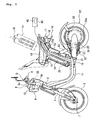
- Fig. 1 is a side view of an electric motorcycle 1 according to an embodiment of the present invention
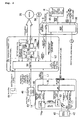
- Fig. 2 is a block diagram of an electric system of the electric motorcycle 1.
- the electric motorcycle 1 includes a head pipe 2 at the upper front portion of a vehicle body thereof, and a steering shaft, not shown, for changing the direction of the vehicle body is rotatably inserted through the head pipe.
- a handle supporting member 3 to which a handle 3a is fixed is mounted at the upper end of the steering shaft, and a grip 4 is mounted to both ends of the handle 3a.
- a grip G on the right side not shown (far side in Fig. 1) constitutes a rotatable throttle grip.
- a pair of left and right front forks 5 are mounted so as to extend downwardly of the lower end of the head pipe 2.
- a front wheel 6 is attached to the lower ends of the front forks 5 via the front axle 7, and the front wheel 6 is rotatably supported by the front axle 7 in a state of being suspended so as to be dumped by the front forks 5.
- a display control unit 8 including a meter 8a integrally provided with a display unit formed, for example, of liquid crystal for displaying the charged state of a battery, the traveling state of the electric motorcycle 1, the traveling mode, and so on, which will be described later, an alarm output unit for supplying an alarm sound (electronic buzzer or the like), and an input unit including a plurality of switches (three switches, for example) for entering information such as values or characters is disposed forwardly of the handle 3a of the handle supporting member 3.
- a head lamp 9, which is auxiliary equipment (including lamps, alarms, and switches for controlling the same) H is fixed to the handle supporting member 3 at the position downwardly of the meter 8a. Flasher lamps 10, which are auxiliary equipments H (only one of them is shown in Fig. 1), are provided on both sides of the head lamp 9, respectively.
- a pair of left and right vehicle body frames 11 shaped substantially like a letter L in side view extends from the head pipe 2 toward the rear of the vehicle body.
- the vehicle body frames 11 are shaped like a round pipe, and extend obliquely downward from the head pipe 2 toward the rear of the vehicle body, and then extend horizontally toward the rear to be shaped substantially like a letter L in side view.
- a pair of left and right seat rails 12 extend from the rear side ends of the pair of vehicle body frames 11 obliquely upward toward the rear, and the rear ends 12a of the seat rails 12 are bent toward the rear along the shape of a seat 13.
- a battery box 14 is detachably disposed between the pair of left and right seat rails 12 (the removed state is shown by chain double-dashed lines in Fig. 1), and a plurality of rechargeable batteries (secondary battery; for example, a lithium ion battery) 14a are stored in the battery box 14.
- secondary battery for example, a lithium ion battery
- a seat stay 15 shaped like an inverted letter U is welded to the pair of left and right seat rails 12 in the vicinity of the bent portions so as to be inclined upward toward the front of the vehicle body, and the seat 13 is disposed in a portion enclosed by the seat stay 15 an the left and the right seat rails 12 so as to be capable of opening and closing, that is, the front end of the seat 15 is capable of rotating in the vertical direction.
- a rear fender 16 is attached to the rear end of the seat rail 12, and a tail lamp 17, which is auxiliary equipment H, is mounted to the rear surface of the rear fender 16.
- a flash lamps, which are auxiliary equipments H, (only one of them is shown in Fig. 1) 18 are attached to the left side and the right side of the tail lamp 17.
- rear arm brackets 19 (only one of them is shown in Fig. 1) are welded to the horizontal portion of the pair of left and right vehicle body frames 11 below the seat 13, and the front end of a rear arm 20 is pivotably supported by a pair of left and right rear arm brackets 19 via a pivot shaft 21.
- a side stand 25 is rotatably supported by the rear arm 20 on the left side via a shaft 26 on the rear side of the horizontal portions of the pair of left and right vehicle body frames 11, and the side stand 25 is urged by a return spring 27 in the closing direction.
- An axial gap type electric vehicle 28 connected to the rear wheel 22 for rotating the rear wheel 22 (hereinafter may be referred to simply as electric vehicle 28), and a vehicle controller (hereinafter, may be also referred to as VTC) 29 electrically connected to the electric vehicle 28 for driving the electric vehicle 28 are mounted at the portion between the rear ends 20a of the rear arms 20.
- VTC vehicle controller
- a BMC microcomputer 35 which is a battery management controller, connected to the battery 14a for managing electric charge to the battery 14a and electric discharge from the battery 14a is provided in the battery box 14.
- the display control unit 8 is, as shown in Fig. 1 and Fig. 2, provided with a meter controller 39 including a meter microcomputer 38 for controlling the display mode of the display unit of the meter 8a and driving of the auxiliary equipment H.
- the BMC microcomputer 35 in the battery box 14 is constructed in such a manner that a connector of the battery charger 40 can be attached to and detached from (can be brought into and out of electrical contact with the microcomputer 3) a connector electrically connected to the battery 14a and the BMC microcomputer 35 via an insertion port IS for electric charge.
- the battery charger 40 is capable of charging the battery 14a under the control of the BMC microcomputer 35 in a state of being electrically connected to the battery 14a and the BMC microcomputer 35 (in a state in which the connector of the battery charger 40 is attached to the connector which is connected to the BMC microcomputer 35).
- the battery charger 40 is provided with a battery charger controller (hereinafter, referred to as battery charger microcomputer) 42 for controlling the output current and/or the output voltage during charging operation by the battery charger 40 (the charging section thereof), as shown in Fig. 1 and Fig. 2.
- battery charger microcomputer a battery charger controller for controlling the output current and/or the output voltage during charging operation by the battery charger 40 (the charging section thereof), as shown in Fig. 1 and Fig. 2.
- a main switch 44 for turning the VTC 29 ON/OFF by operating the driver is provided in the vicinity of the meter 8a.
- the throttle grip G is rotatable about the axis thereof, and the throttle grip G is provided therein with a completely closing switch 46 for transmitting a completely closing signal to the VTC 29 by turning the switch ON when it is rotated to the completely closed position.
- a potentiometer 48 connected to the throttle grip G with a wire for detecting the amount of rotation based on the rotation of the throttle grip G and transmitting the result as a potential difference value of throttle to the VTC 29.
- the completely closing switch 46 and the potentiometer 48 constitute a throttle unit 49.
- the VTC 29 is, as shown in Fig. 2, provided with a microcomputer 50.
- the VTC microcomputer 50 can communicate with the BMC microcomputer 35 via a first communication path L1 for two systems (for transmitting and receiving); fixed line and/or wireless, and the VTC microcomputer 50 can communicate with the meter microcomputer 38 via a second communication path L2 of two systems; fixed line and/or wireless.
- the BMC microcomputer 35 and the meter microcomputer 38 are connected in series by the first communication path L1 and the second communication path L2 with the VTC (VTC microcomputer) 50 interposed therebetween.
- the first communication path L1 is a path between the BMC microcomputer 35 and the VTC microcomputer 50,though which signals indicating information on vehicle control or the state of the battery, are communicated (transmitted and received)
- the second communication path L2 is a path between the VTC microcomputer 50 and the meter microcomputer 38,through which signals indicating information, such as vehicle control or the state of the battery, are communicated (transmitted and received).
- the VTC 29 is also connected to the VTC microcomputer 50, and is provided with a mutual observation circuit 51 for observing the operating state of the VTC microcomputer 50.
- the VTC microcomputer 50 has a function to observe the operating state of the mutual observation circuit 51.
- the VTC 29 is provided with a logical output unit 53 for supplying a logical signal based on a switching signal of the main switch 44, a control signal of the VTC microcomputer 50, and an observation signal from the mutual observation circuit 51.
- the VTC 29 is provided with a power module 54 including an inverter for supplying three-phase current to the motor 28 and rotating the motor 28, and a gate drive 55 for controlling a gate signal for driving the inverter of the power module 54 and controlling the number of revolution of the motor 28 through the power module 54.
- the gate drive 55 is connected to the logical output unit 53 so as to actuate when the logical output of the logical output unit 53 is at High level, and stop operation when it is in Low level (High level > Low level).
- a CT is a current sensor for detecting three-phase current output from the power module 54 and feeding the result back to the VTC microcomputer 50, and the power module 54 is provided therein a temperature sensor T1 for detecting the temperature of the power unit in the power module 54.
- the motor 28 is provided with an encoder (ENC) 56 for detecting the number of revolution of the motor 28, and the output of the number of revolution of the encoder 56 is fed back to the VTC microcomputer 50.
- EEC encoder
- the battery box 14 includes, as shown in Fig. 2, a remaining quantity display LED 60 mounted to one surface thereof as a meter for displaying the remaining quantity of the battery 14a in response to the drive signal from the BMC microcomputer 35, an electric charge switch 61 connected to the battery charger 40 when the battery box 14 is mounted for controlling ON/OFF of charging operation of the battery charger 40 in response to a control signal from the BMC microcomputer 35, and a sensor 62 connected to the battery 14a and also connected to the battery charger 40 when the battery box 14a is mounted.
- the sensor 62 is constructed to detect a charging current supplied (outputted) to the battery 14a from the battery charger 40 and a discharging current discharged (including discharge during travel of the vehicle and natural self-discharge) from the battery 14a. The detected values of the charging and discharging current are transmitted to the BMC microcomputer 35.
- each battery (single cell) of the battery 14a or the total voltage is transmitted to the BMC microcomputer 35 respectively, and the temperature in the battery 14a is transmitted to the BMC microcomputer 35 via a thermistor.
- a meter controller 36 is connected to the VTC 29 via the second communication path L2, and is provided with an auxiliary equipment disconnecting switch 65 connected to the auxiliary equipment H via an auxiliary equipment power supply line.
- the auxiliary equipment disconnecting switch 65 can turn ON and OFF the power supply to the auxiliary equipment H.
- the VTC microcomputer 50 is connected to the battery 14a without the intermediation of the BMC microcomputer 35, so that the voltage of the battery 14a can be detected.
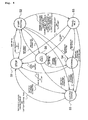
- Fig. 3 is a drawing showing the construction of the circuit relating to the mutual activation among the VTC microcomputer 50, the BMC microcomputer 35, and the meter microcomputer 38, which are not shown in Fig. 2.
- the VTC 29 is provided with a VTC power supply circuit 69, a VTC communication transmission circuit 70, and a VTC communication reception circuit 71, and is connected to the BMC microcomputer 35 via the VTC communication transmission circuit 70, the VTC communication reception circuit 71, and the communication path L1.
- the VTC microcomputer 50 is provided with a VTC communication transmission circuit 72 and a VTC communication reception circuit 73, and is connected to the meter microcomputer 38 via the VTC communication transmission circuit 72, the VTC communication reception circuit 73 and the communication path L2.
- the VTC power supply circuit 69 includes a VTC power source 69a for supplying a power for operating the VTC 29 (VTC microcomputer 50), and a VTC power source control circuit 69b for turning ON and OFF the VTC power source 69a, and the VTC power source control circuit 69b is provided with a VTC power source transistor (Tr).
- the collector terminal of the VTC power source Tr is connected to the VTC power source 69a, and the base terminal is connected to one system (L1 a) of the first communication path L1.
- the VTC communication transmission circuit 70 is provided with a transmission transistor (Tr) 70a, and a base terminal of the transmission Tr 70a is connected to the VTC microcomputer 50, and a collector terminal is connected to the other system L1b of the first communication path L1.
- Tr transmission transistor
- the VTC communication reception circuit 71 is provided with a reception transistor (Tr) 71 a, and a collector terminal of the reception Tr71 a is connected to the VTC microcomputer 50.
- a base terminal of the reception Tr71 a is connected to a line which connects the base terminals of the first communication path L1a and the VTC power source Tr.
- the VTC communication transmission circuit 72 is provided with a transmission transistor (Tr) 72a and a base terminal of the transmission Tr 72a is connected to the VTC microcomputer 50, and a collector terminal is connected to one of the systems L2a of the second communication path L2.
- the VTC communication reception circuit 73 is provided with a reception transistor (Tr) 73a, and a collector terminal of the reception Tr 73a is connected to the VTC microcomputer 50. A base terminal of the reception Tr 73a is connected to the other system L2b of the second communication path L2.
- the battery box 14 is provided with a BMC power source circuit 74, a BMC communication transmission circuit 75, and a BMC communication reception circuit 76, and is connected to the VTC microcomputer 50 via the BMC communication transmission circuit 75, the BMC transmission reception circuit 76, and the communication path L1.
- the BMC power source circuit 74 is provide with a BMC power source 74a for supplying a power for operating the BMC microcomputer 35, and a BMC power source control circuit 74b for turning ON and OFF the BMC power source 74a, and the BMC power source control circuit 74b is provided with a BMC power source transistor (Tr).
- a collector terminal of the BMC power source Tr is connected to the BMC power source 74a, and a base terminal is connected to the first communication path L1b.
- the BMC communication transmission circuit 75 is provided with a transmission transistor (Tr) 75a, and a base terminal of the transmission Tr 75a is connected to the BMC microcomputer 35, and a collector terminal is connected to the first communication path L1a.
- Tr transmission transistor
- the BMC communication reception circuit 76 is provided with a reception transistor (Tr) 76a, and a collector terminal of the reception Tr 76a is connected to the BMC microcomputer 35. A base terminal of the reception Tr 76a is connected to the first communication path L1 b.
- the display control unit 8 is provided with a meter power source circuit 77, a meter communication transmission circuit 78, and a meter communication reception circuit 79, and is connected to the VTC microcomputer 50 via the meter communication transmission circuit 78, the meter communication reception circuit 79, and the second communication path L2a.
- the meter power circuit 77 includes a meter power source 77a for supplying a power for operating the meter microcomputer 38, and a meter power source control circuit 77b for turning ON and OFF the meter power source 77a.
- the meter power source control circuit 77b is provided with a meter power source transistor (Tr).
- Tr meter power source transistor
- a collector terminal of the meter power source Tr is connected to the meter power source 77a, and a base terminal is connected to the second communication path L2a.
- the meter communication transmission circuit 78 is provided with a transmission transistor (Tr) 78a and a base terminal of the transmission Tr 78a is connected to the BMC microcomputer 35, and a collector terminal is connected to the second communication path L2b.
- Tr transmission transistor
- the meter communication reception circuit 79 is provided a reception transistor (Tr) 79a, and a collector terminal of the reception Tr 79a is connected to the meter microcomputer 38. A base terminal of the reception Tr 79a is connected to the second communication path L2a.
- the battery 14a is connected to an emitter terminal of the BMC power source transistor Tr in the battery box 14, an emitter terminal of the VTC power source Tr in the VTC 29, and an emitter terminal of the meter power source Tr of the display control unit 8.
- a collector terminal of a transistor (Tr) 88 and a collector terminal of a transistor (Tr) 89 are connected to predetermined midpoints of a line which connects the first communication path L1b and the base terminal of the BMC power source Tr, respectively, so that an activation signal is transmitted from the battery charger 40 to the base terminal of Tr 88.
- a base terminal of the Tr 89 is connected to the BMC microcomputer 35, so that a self-activation signal from the BMC microcomputer 35 can be transmitted to the base terminal of the BMC power source transistor Tr via the Tr 89.
- a collector terminal of a transistor (Tr) V1 is connected to the base terminal of the VTC power source Tr, so that ON/OFF signals from the main switch 44 are input to the base terminal, and the VTC power source transistor Tr can be activated/stopped in response to the ON/OFF signals.
- a base terminal of a transistor (Tr) M1 is connected to the meter microcomputer 38, and a collector terminal is connected to a base terminal of the meter power source Tr, so that a self-activation signal from the meter microcomputer 38 can be supplied to the base terminal of the meter power source transistor Tr.
- the ON signal is transmitted to a transistor TrV1, and the transistor V1 is turned ON.
- the VTC power source Tr By turning the transistor V1 ON, the VTC power source Tr is turned ON, and consequently, a voltage signal of the battery 14a is supplied to the VTC power source 69a via the VTC power source Tr, and the VTC microcomputer 50 is activated by the VTC power source 69a.
- the activated VTC microcomputer 50 turns the transmission transistor 70a in the VTC communication transmission circuit 70 ON, as shown by broken lines B3 in the drawing, and thus the transistor 76a of the BMC communication reception circuit 76 is turned ON. Consequently, a current flows from the BMC power source Tr through a diode D to the transistor 76a, and the BMC power source Tr is turned ON. As a consequence, a voltage signal of the battery 14a is supplied through the BMC power source Tr to the BMC power source 74a, and the BMC microcomputer 35 is activated by the BMC power source 74a.
- Activation of the meter microcomputer 38 is the same as the path shown by broken lines B2.
- VTC microcomputer 50 it is possible to activate the VTC microcomputer 50 in advance by turning the main switch 44 ON, and then activating the BMC microcomputer 35 and the meter microcomputer 38 by the VTC microcomputer 50.
- the BMC microcomputer 35 stops operation of the VTC microcomputer 50 as described above.
- the operation of the meter microcomputer 38 is stopped, and the operation of the BMC microcomputer 50 itself is also stopped. Consequently, the operation of the entire system of the electric motorcycle 1 is stopped (shut down).
- VTC power source Tr is turned OFF and supply of a voltage signal of the battery 14a to the VTC power source 69a is blocked off, and the operation of the VTC microcomputer 50 is stopped.
- the transmission transistor 70a and the transistor 76a of the BMC communication reception circuit 76 are turned OFF, respectively, and, as a consequence, the BMC power source Tr is turned OFF. Accordingly, supply of a voltage signal of the battery 14a to the BMC power source 74a is blocked off, and thus the operation of the BMC microcomputer 35 is stopped.
- the transmission transistor 72a of the VTC communication transmission circuit 72 is turned OFF, and thus the meter power source Tr is turned OFF. Consequently, supply of a voltage signal of the battery 14a to the meter power source 77a is blocked off, and thus the operation of the meter microcomputer 38 is stopped.
- the activated microcomputer can activate the other microcomputer via the first communication path L1 in response to the activation of itself.
- the operation of one of the BMC microcomputer 35 and the VTC microcomputer 50 is stopped in response to disconnection of the battery charger 40 or turning the main switch 44 OFF, the operation of the other microcomputer can be stopped via the first communication passage L1 by the previously stopped microcomputer.
- the meter microcomputer 38 can be activated/stopped via the second communication path L2 in response to activation/stop of the VTC microcomputer 50.
- the VTC microcomputer 50 activates other microcomputers (the BMC microcomputer 35, the meter microcomputer 38), respectively, it is necessary to transmit trigger signals for activation to the VTC microcomputer 50 in a concentrated manner in various scenes in which the other microcomputers are needed to be activated (for example, connection of the battery charger 40, turning ON of the main switch 44).
- the plurality of microcomputers (the VTC microcomputer 50, the BMC microcomputer 35, and the meter microcomputer 38) and sensors are disposed away from each other as in the case of the electric motorcycle 1, wiring have to be made for the VTC microcomputer 50 from the position away from the VTC microcomputer 50, and wiring may become complex.
- the VTC microcomputer 50 and the BMC microcomputer 35 can activate/stop with respect to each other via the first communication passage L1, and the meter microcomputer 38 may be activated/stopped in response to activation/stop of the VTC microcomputer 50. Therefore, the system of the electric motorcycle 1 can be activated/stopped with a simple construction.
- the VTC power source control circuit 69b, the BMC power source control circuit 74b, and the meter power source control circuit 77b which are power source control circuits independently of the VTC microcomputer 50, the BMC microcomputer 35, and the meter microcomputer 38 are provided, it is not necessary to keep the respective microcomputers 50, 35, 38 in a waiting state any more. Consequently, the power consumption can be reduced, and the reliability may be improved.
- the first communication path L1 between the VTC microcomputer 50 and the BMC microcomputer 35 is constructed as a shared path that can communicate the signals for mutual activation/stop together with signals indicating information on vehicle control and the state of the battery, the system construction can be simplified in comparison with the case in which the signal communication path for mutual activation is provided separately from the signal communication path showing information on the vehicle control and the state of the battery.
- activation/stop by controlling the main switch 44, and the activation/stop in response to start/termination of electric charge can be realized in a simple construction, respectively.
- Fig. 4 is a drawing showing a state transfer in which the electric motorcycle 1 according to the present embodiment (a system composed of the VTC 29, the BMC microcomputer 35, the meter microcomputer 38, and the battery charger microcomputer 42 (during electric charge)) can be transferred.
- the VTC microcomputer 50 determines whether or not the battery charger 40 is electrically connected to the BMC microcomputer 35 via the BMC microcomputer 35.
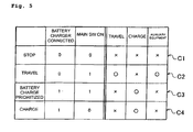
- the VTC microcomputer 50 When the connecting state was not found as a result of this determination, the VTC microcomputer 50 is transferred to the state of waiting start S2 shown in Fig. 4, and then starts power supply to the auxiliary equipment H by transmitting an auxiliary-equipment-power-supply-ON signal to the auxiliary equipment disconnecting switch 65 (C2 in Fig. 5).
- the VTC microcomputer 50 stops power supply to the auxiliary equipment H by transmitting an auxiliary-equipment-power-supply-OFF signal to the auxiliary equipment disconnecting switch 65, and gives electric charge from the battery charger 40 to the battery 14a top priority (the state (charging mode) S3 in Fig. 4, C3 in Fig. 5) even when the main switch 44 is in an ON-state.
- the VTC microcomputer 50 When information indicating that the battery charger 40 is connected to the BMC microcomputer 35 is transmitted from the BMC microcomputer 35 in a case in which the main switch 44 is OFF ("0"), the VTC microcomputer 50 maintains the state S3 in Fig. 4, and allows only electric charge from the battery charger 40 to the battery 14a (C4 in Fig. 5).
- the usage (electric discharge) of the battery 14a may be minimized by blocking off energization to the auxiliary equipment H, which may affect to the remaining quantity (electric discharge) of the battery 14a.
- the capacity of the battery 14a can be controlled accurately by the BMC microcomputer 35, and the battery 14a can be charged accurately.
- the relay 101 when a relay 101 is mounted in the construction according to the present embodiment, as shown in Fig. 6(a), the relay 101 is actuated in response to turning-ON operation of a kill switch 100 by the driver, and thus the VTC microcomputer 50 detects turning ON of the kill switch 100, so that energization from the gate drive 55 and the power module 54 to the motor 28 can be blocked off by the VTC microcomputer 50.
- the operation signal (speaking accurately, an OFF signal "0" which is an inverted signal) is transmitted to the gate of each transistor of the gate drive 55 directly in response to turning ON operation of the motor stop switch 102 by the driver. Consequently, energization from the gate drive 55 and the power module 54 to the motor 28 can be blocked off.
- the driver can perform the emergency stop operation of the motorcycle 1 without employing an expensive relay, and thus the total cost of the motorcycle 1 can be reduced.
- system ON/OFF signals from the main switch 44 can be transmitted to the gate drive 55 directly via the logical output unit 53. Therefore, it is also possible to control the signal transmitted from the logical output unit 53 to the gate of each transistor of the gate drive 55 to "0", and block energization from the gate drive 55 and the power module 54 to the motor 28 off by turning the main switch 44 ON and transmitting the inverted output ("0") to the logical output unit 53.
- the motor stop switch 102 is not necessarily required.
- the VTC microcomputer 50 stores data of the motorcycle 1 under such abnormal condition in a memory in the VTC microcomputer 50, and displays it via the meter 8 as needed.
- data indicating the abnormal state stored in the memory of the VTC microcomputer 50 can be transmitted to the communication equipment by connecting communication equipment having a protocol which differs from the protocol of the meter microcomputer 38 to the communication path L2 between the VTC microcomputer 50 and other microcomputers (such as meter microcomputer 38) with a coupler or the like.
- the VTC microcomputer 50 determines the switching in accordance with the protocol. In other words, the VTC microcomputer 50 transmits a signal indicating the protocol of the meter to the meter microcomputer 38 and waits for response from the meter microcomputer 38. Then, when no response is received, it transmits a signal having the protocol of the communication equipment and waits for the response from the communication equipment.
- the VTC microcomputer 50 of the electric motorcycle 1 does not transfer immediately to the travelable state even when the main switch 44 is turned ON in the start waiting state S2, but it is brought into the travelable state S5 by some actions performed subsequently (for example, when one of the plurality of switches on the meter 8 is operated).
- the throttle unit 49 is constructed into a dual-system of the potentiometer 48 and the completely closing switch 46 as shown in Fig. 2, it is also possible to allow transfer to the travelable state S5 only when the driver turns the throttle to the completely closed position once to turn the completely closing switch 46 ON from the start waiting state S2, and the potential difference value transmitted from the potentiometer 48 is included within the range of completely closed state, whereby further reliable travel is enabled.
- the throttle unit 49 is constructed into a dual-system of the potentiometer 48 and the completely closing switch 46. Therefore, abnormalities of the potentiometer 48 (for example, fixation due to freezing or the like) can be detected if the potential difference value of the potentiometer 48 exceeds a threshold value for abnormality detection as shown in Fig. 8 when the completely closing switch 46 is turned from ON to OFF.
- the state of abnormalities can be displayed on the meter 8 via the meter microcomputer 38.
- the state transition S3 in a state of being charged, the quantity of the battery in a state of being charged can be displayed on the meter 8 via the meter microcomputer 38, and also on the remaining quantity display LED 60 of the battery box 14.
- the driver inputs a personal identification number through a plurality of switches on the input unit of the meter (display control unit) 8.
- the input personal identification number is transmitted to the VTC microcomputer 50 via the meter microcomputer 38, and stored in the memory of the VTC microcomputer 50.
- the state of the electric motorcycle 1 (VTC microcomputer 50) is transferred to the anti-theft state S6. Therefore, even when the operation for transferring from the start waiting state S2 to the above-described travelable state S5, for example, is performed by the driver, the vehicle is not transferred to the travelable state S5 unless the personal identification number is input through the plurality of switches on the input unit, then the VTC microcomputer 50 determines that the input personal identification number and the personal identification number stored in the memory are identical (release of anti-theft mode), and the vehicle is transferred to the start waiting state S2.
- the dischargeable limit of the battery 14a is detected by the BMC microcomputer 35.
- the BMC microcomputer 35 compares the preset lower limit value of the battery voltage and the current battery voltage and determines that electric discharge is terminated when the current battery voltage is lower than the lower limit value.
- the battery voltage value is detected also by the VTC microcomputer 50, comparison between the preset lower limit value of the battery voltage and the curren' battery voltage to determine termination of electric discharge by the VTC microcomputer 50 in case of the BMC microcomputer 35 failure.
- termination of electric discharge can be determined by the use of the battery voltage detecting function of the VTC microcomputer 50 without damaging the battery, and thus the vehicle can be traveled until the termination of the electric discharge.
- the VTC microcomputer 50 does not generate engine idle sound when the vehicle is transferred from the start waiting state S2 to the travelable state S5.
- the VTC microcomputer 50 generates an idle alarm sound automatically via the display control unit 8 or the like only when the vehicle is in the travelable state S5, and is stopped, and the throttle of the throttle unit 49 is completely closed.
- the driver can turn the idle alarm sound off by gripping the brake, so that generation of unintended alarm sound may be prevented.
- the blinking of a winker can be also realized by an electronic buzzer via the display control unit 8.
- the BMC controller 35 of the electric motorcycle 1 in the present embodiment being normally in a sleeping state (low power consumption state), is driven by the VTC controller 50 or the like at predetermined intervals, and accumulates the quantity of electric discharge (quantity of electric discharge during usage, and quantity of self discharge), which is observed as a capacity learning value.
- the VTC microcomputer 50 will have a difficulty to activate the BMC microcomputer 35.
- the BMC microcomputer 35 can detect and accumulate a discharging current, which cannot be detected normally, to minimize the accumulation error by detecting the presence of a flowing current and activating automatically, or by activating at regular intervals.
- the BMC microcomputer 35 can prohibit the capacity learning to prevent the error from being entered in the learned value.
- prohibition of the capacity learning is stored and continued until the normal electric charge is terminated, and then is released upon normal termination of electric charge, so that the capacity learning is restarted.
- one controller can activate/stop the other controller via the first communication path for communication between those controllers in response to activation of itself. Therefore, the system of the electric vehicle can be activated/stopped in a simple construction.
- the first power source control circuit, the second power source control circuit, and the third power source control circuit independently of the first controller, the second controller, and the fourth controller. Therefore, it is not necessary to keep each controller in a waiting state. Consequently, power consumption can be reduced, and reliability may be improved.
- the first communication path between the first controller and the second controller is constructed as a shared path that can be used for communicating an activation signal from one controller to the other controller together with a signal indicating information on the vehicle and the battery. Therefore, the system construction can be simplified.
- activation/stop operation in response to activation/stop operation and starting/termination of charging by the operation of the main switch can be realized in a simple structure, respectively.
- a motor 28, a VTC microcomputer 50 for controlling the motor 28, a battery 14a being chargeable and supplying a power to the motor 28, a BMC microcomputer 35 connected to the battery 14a for managing charging to the battery 14a and discharging from the battery 14a, and a first communication path L1 for communication between the VTC microcomputer 50 and the BMC microcomputer 35 are provided, and the VTC microcomputer 50 and the BMC microcomputer 35 each are provided with a mutual actuating unit for actuating the other microcomputer via the first communication path L1 in response to actuation of its own microcomputer.
- an electric vehicle comprises a motor, a first controller for controlling the motor, a battery being chargeable and supplying electric power to the motor, a second controller connected to the battery for controlling electric charge for the battery and electric discharge from the battery, and a first communication path for communication between the first controller and the second controller, wherein the second controller activates the first controller via the first communication path when electric charge to the battery is started in a state in which the first controller is not in the activated state.
- It may further comprise a battery charger, which can be brought into and out of electrical contact with the battery and the second controller, for charging the battery in the state of being electrically connected to the battery and the second controller, and the battery charger including a third controller for controlling an output current and/or an output voltage during charging operation of the battery charger, wherein the third controller activates the second controller when the battery charger is electrically connected to the second controller.
- a battery charger which can be brought into and out of electrical contact with the battery and the second controller, for charging the battery in the state of being electrically connected to the battery and the second controller
- the battery charger including a third controller for controlling an output current and/or an output voltage during charging operation of the battery charger, wherein the third controller activates the second controller when the battery charger is electrically connected to the second controller.
- such an electric vehicle may further comprise a display unit for displaying the charged state of the battery, and a fourth controller having a second communication path for the first controller for controlling the display mode of the display unit, wherein the first controller activates the fourth controller via the second communication path when the fist controller itself is activated.
- an electric vehicle comprises a motor, a first controller for controlling the motor, a battery being chargeable and supplying electric power to the motor, a second controller connected to the battery for controlling electric charge for the battery and electric discharge from the battery, a first communication path for communication between the first controller and the second controller, a display unit for displaying the charged state of the battery, and a third controller having the second communication path for the first controller and controlling the display mode of the display unit, wherein the second and the third controllers are connected in series by the first communication path and the second communication path with the first controller interposed therebetween, and the first and the second controllers can be activated each other.
- an electric vehicle further comprises a battery charger which can be brought into and out of electrical contact with the battery and the second controller for charging the battery in a state of being electrically connected to the battery and the second controller, and the battery charger including a fourth controller for controlling an output current and/or an output voltage while the battery charger is charged, wherein the fourth controller activates the second controller when the battery charger is electrically connected to the second controller, the activated second controller activates the first controller via the first communication path, and the activated first controller activates the third controller via the second communication path.
- the electric vehicle is provided with a plurality of controllers including a controller for motor control and a controller for battery management. All the embodiments described before may be combined with each other in a desired combination.
Description
- The present invention relates to an electric vehicle in which wheels are driven by a motor supplied with power from a battery.
- In recent years, there is growing interest in electric vehicles such as electric motorcycles and the like in which wheels are driven by a motor supplied with power from a battery due to global environment problems and traffic environment problems.
- Since the electric vehicle is supplied with power from a battery, the battery capacity (electric capacity) is reduced by electric discharge based on the usage of the battery.
- Therefore, the battery capacity is replenished by connecting an battery charger to the battery, and charging the battery by the battery charger.
- Therefore, it is important to control the charging and discharging state of the battery. Therefore, the electric vehicle is provided with a controller for battery management for controlling the charging and discharging state of the battery (battery management controller; BMC) separately in addition to a controller for controlling the motor, such as, for example, known from
JP-A-11-89011 JP-A-11-266510 -
EP-A-0 644 079 according to the preamble ofclaim 1 discloses an electric vehicle having an electric motor for driving the vehicle, a chargeable battery supplying electric power to the motor, a running control portion and a battery monitor/charge control portion interconnected by communication lines. Both control portions include an actuating unit for actuating the other control portion. - It is the object of the present invention to provide a simple structured electric vehicle having a number of controllers.
- This object is solved by the features of
claim 1. - According to the invention, a communication path for communication between a first controller and a second controller is also a path for transmitting an information signal concerning the battery or the vehicle. Thus, the communication path is effectively utilized, since it is not necessary to configure a path for transmitting a signal to start up the other controller.
- Preferably, both of the first and the second controllers each include a mutual actuating unit for actuating the other controller via the first communication path in response to actuation of its own controller.
- Alternatively or additionally, an electric vehicle of the kind cited at the beginning is configured in that the first controller includes a first power source for actuating and stopping the controller itself and a first power source control circuit for turning ON and OFF the power source, the first communication path includes a first path for connecting the second controller and the first power source control circuit, the second controller transmits an activation signal to the first power source control circuit via the first passage when electric charging to the battery is started in a state in which the first controller is not activated, and the first controller is adapted to be started by tuming-ON operation of the first power source by the first power source control circuit in response to the transmitted activation signal.
- Preferably, a battery charger is provided which can be brought into and out of electrical contact with the battery and the second controller, for charging the battery in the state of being electrically connected to the battery and the second controller, the battery charger including a third controller for controlling an output current and/or an output voltage during charging operation of the battery charger.
- Furthermore, according to a preferred embodiment, a second communication path for communicating between the second controller and the third controller is provided, wherein the second controller includes a second power source for actuating and stopping the controller itself and a second power source control circuit for turning ON and OFF the second power source. Therein, the second communication path includes a second path for connecting the third controller and the second power source control circuit, the third controller transmits an activation signal to the second power source control circuit via the second path when the battery charger is electrically connected to the battery in a state in which the second controller is not activated, and the second controller is actuated by turning-ON operation of the second power source by the second power source control circuit in response to the transmitted activation signal.
- Moreover, the third controller transmits a stop signal to the second power source control circuit via the second path when the battery charger is electrically disconnected from the battery when the first and the second controllers are activated, the second controller stops activating by turning-OFF operation of the second power source by the second power source control circuit in response to the transmitted stop signal, the first power source control circuit turns OFF the first power source in response to the stop of activation of the second controller and/or an activation stopping signal transmitted from the second controller, and the first controller stops activation by the turning-OFF operation of the first power source.
- An embodiment of the electric vehicle includes a display unit for displaying the charged state of the battery, a fourth controller for controlling the displaying mode of the display unit, and a third communication path for communicating between the first controller and the fourth controller, the fourth controller includes a third power source for activating and stopping the controller itself and a third power source control circuit for turning ON and OFF the third power source, the third communication path including a third path for connecting the first controller and the third power source control circuit, wherein the first controller transmits an activation signal to the third power source control circuit via the third path in response to activation of the controller itself in a state in which the fourth controller is not activated, and the fourth controller is activated by turning-ON operation of the third power source by the third power source control circuit in response to the transmitted activation signal.
- Therein, the first communication path includes a fourth path for connecting the first controller and the second power source control circuit, the first controller transmits the activation signal to the second power source control circuit via the fourth path in response to activation of itself in a state in which the second controller is not activated, and the second controller is activated by turning-ON operation of the second power source by the second power source control circuit in response to the transmitted activation signal.
- Further, another embodiment includes a main switch connected to the first controller and capable of being turned ON and OFF, and the first controller is activated by turning-ON operation of the main switch and stops operation by tuming-OFF operation of the main switch.
- Such a main switch is connected to the first controller and is capable of being turned ON and OFF, the first controller is activated by turning ON operation of the main switch, the activated first controller transmits an activation signal to the second power control circuit via the fourth path, the second controller is activated by turning ON operation of the second power source by the second power source control circuit in response to the transmitted activation signal, the first controller shifts the operation mode of the controller itself to a charging mode when the battery charger is electrically connected to the battery with the main switch turned ON and stops operation when the battery charger is electrically disconnected from the battery.
- Further preferred embodiments are subject to the subclaims.
- In the following, the invention will be described in more detail by means of preferred embodiments thereof in conjunction with the accompanying drawings, wherein:
- Fig. 1
- is a side view of an electric motorcycle according to an embodiment of the present invention, showing an example of an apparatus on which an axial gap type dynamo-electric machine is mounted,
- Fig. 2
- is a block diagram of an electric system of the motorcycle shown in Fig. 1,
- Fig. 3
- is a drawing showing the construction of the circuit relating to the mutual activation among the VTC microcomputer, the BMC microcomputer, and the meter microcomputer, which are not shown in Fig. 2,
- Fig. 4
- is a drawing showing a state transfer in which the electric motorcycle according to the present embodiment can be transferred,
- Fig. 5
- is an explanatory drawing showing a controlling state with a battery charger connected,
- Fig. 6(a)
- is an explanatory drawing illustrating a process of blocking energization to a motor off with a relay mounted,
- Fig. 6(b)
- is an explanatory drawing illustrating a process of blocking energization to a motor off with no relay mounted,
- Fig. 7
- is an explanatory drawing showing a pushing operation of the electric motorcycle which is in the start waiting state according to the present embodiment, and
- Fig. 8
- is an explanatory drawing illustrating a process of detecting fixation of a potentiometer at a throttle unit according to the present embodiment.
- As an electric vehicle according to the present invention, in particular, an embodiment of an electric motorcycle will be described, referring to attached drawings.
- Fig. 1 is a side view of an
electric motorcycle 1 according to an embodiment of the present invention, and Fig. 2 is a block diagram of an electric system of theelectric motorcycle 1. - As shown in Fig. 1 and Fig. 2, the
electric motorcycle 1 includes ahead pipe 2 at the upper front portion of a vehicle body thereof, and a steering shaft, not shown, for changing the direction of the vehicle body is rotatably inserted through the head pipe. Ahandle supporting member 3 to which ahandle 3a is fixed is mounted at the upper end of the steering shaft, and a grip 4 is mounted to both ends of thehandle 3a. A grip G on the right side not shown (far side in Fig. 1) constitutes a rotatable throttle grip. - A pair of left and right
front forks 5 are mounted so as to extend downwardly of the lower end of thehead pipe 2. Afront wheel 6 is attached to the lower ends of thefront forks 5 via the front axle 7, and thefront wheel 6 is rotatably supported by the front axle 7 in a state of being suspended so as to be dumped by thefront forks 5. - A
display control unit 8 including ameter 8a integrally provided with a display unit formed, for example, of liquid crystal for displaying the charged state of a battery, the traveling state of theelectric motorcycle 1, the traveling mode, and so on, which will be described later, an alarm output unit for supplying an alarm sound (electronic buzzer or the like), and an input unit including a plurality of switches (three switches, for example) for entering information such as values or characters is disposed forwardly of thehandle 3a of thehandle supporting member 3. Ahead lamp 9, which is auxiliary equipment (including lamps, alarms, and switches for controlling the same) H is fixed to thehandle supporting member 3 at the position downwardly of themeter 8a.Flasher lamps 10, which are auxiliary equipments H (only one of them is shown in Fig. 1), are provided on both sides of thehead lamp 9, respectively. - A pair of left and right vehicle body frames 11 shaped substantially like a letter L in side view extends from the
head pipe 2 toward the rear of the vehicle body. The vehicle body frames 11 are shaped like a round pipe, and extend obliquely downward from thehead pipe 2 toward the rear of the vehicle body, and then extend horizontally toward the rear to be shaped substantially like a letter L in side view. - A pair of left and right seat rails 12 extend from the rear side ends of the pair of vehicle body frames 11 obliquely upward toward the rear, and the
rear ends 12a of the seat rails 12 are bent toward the rear along the shape of aseat 13. - A
battery box 14 is detachably disposed between the pair of left and right seat rails 12 (the removed state is shown by chain double-dashed lines in Fig. 1), and a plurality of rechargeable batteries (secondary battery; for example, a lithium ion battery) 14a are stored in thebattery box 14. - A
seat stay 15 shaped like an inverted letter U is welded to the pair of left and right seat rails 12 in the vicinity of the bent portions so as to be inclined upward toward the front of the vehicle body, and theseat 13 is disposed in a portion enclosed by the seat stay 15 an the left and the right seat rails 12 so as to be capable of opening and closing, that is, the front end of theseat 15 is capable of rotating in the vertical direction. - A
rear fender 16 is attached to the rear end of theseat rail 12, and atail lamp 17, which is auxiliary equipment H, is mounted to the rear surface of therear fender 16. In addition, a flash lamps, which are auxiliary equipments H, (only one of them is shown in Fig. 1) 18 are attached to the left side and the right side of thetail lamp 17. - On the other hand, rear arm brackets 19 (only one of them is shown in Fig. 1) are welded to the horizontal portion of the pair of left and right vehicle body frames 11 below the
seat 13, and the front end of a rear arm 20 is pivotably supported by a pair of left and rightrear arm brackets 19 via apivot shaft 21. Arear wheel 22, which corresponds to a drive wheel, is rotatably supported at arear end 20a of the rear arm 20, and the rear arm 20 and therear wheel 22 are suspended by arear cushion 23 so as to absorb the impact. - A
side stand 25 is rotatably supported by the rear arm 20 on the left side via ashaft 26 on the rear side of the horizontal portions of the pair of left and rightvehicle body frames 11, and theside stand 25 is urged by areturn spring 27 in the closing direction. - An axial gap type
electric vehicle 28 connected to therear wheel 22 for rotating the rear wheel 22 (hereinafter may be referred to simply as electric vehicle 28), and a vehicle controller (hereinafter, may be also referred to as VTC) 29 electrically connected to theelectric vehicle 28 for driving theelectric vehicle 28 are mounted at the portion between therear ends 20a of the rear arms 20. - As shown in Fig. 1 and Fig. 2, a BMC
microcomputer 35, which is a battery management controller, connected to thebattery 14a for managing electric charge to thebattery 14a and electric discharge from thebattery 14a is provided in thebattery box 14. - The
display control unit 8 is, as shown in Fig. 1 and Fig. 2, provided with a meter controller 39 including ameter microcomputer 38 for controlling the display mode of the display unit of themeter 8a and driving of the auxiliary equipment H. - On the other hand, the
BMC microcomputer 35 in thebattery box 14 is constructed in such a manner that a connector of thebattery charger 40 can be attached to and detached from (can be brought into and out of electrical contact with the microcomputer 3) a connector electrically connected to thebattery 14a and theBMC microcomputer 35 via an insertion port IS for electric charge. Thebattery charger 40 is capable of charging thebattery 14a under the control of theBMC microcomputer 35 in a state of being electrically connected to thebattery 14a and the BMC microcomputer 35 (in a state in which the connector of thebattery charger 40 is attached to the connector which is connected to the BMC microcomputer 35). - The
battery charger 40 is provided with a battery charger controller (hereinafter, referred to as battery charger microcomputer) 42 for controlling the output current and/or the output voltage during charging operation by the battery charger 40 (the charging section thereof), as shown in Fig. 1 and Fig. 2. - In addition, as shown in Fig. 2, a
main switch 44 for turning theVTC 29 ON/OFF by operating the driver is provided in the vicinity of themeter 8a. - On the other hand, the throttle grip G is rotatable about the axis thereof, and the throttle grip G is provided therein with a completely closing
switch 46 for transmitting a completely closing signal to theVTC 29 by turning the switch ON when it is rotated to the completely closed position. There is also provided apotentiometer 48 connected to the throttle grip G with a wire for detecting the amount of rotation based on the rotation of the throttle grip G and transmitting the result as a potential difference value of throttle to theVTC 29. The completely closingswitch 46 and thepotentiometer 48 constitute athrottle unit 49. - The
VTC 29 is, as shown in Fig. 2, provided with amicrocomputer 50. - The
VTC microcomputer 50 can communicate with theBMC microcomputer 35 via a first communication path L1 for two systems (for transmitting and receiving); fixed line and/or wireless, and theVTC microcomputer 50 can communicate with themeter microcomputer 38 via a second communication path L2 of two systems; fixed line and/or wireless. - In other words, in the present embodiment, the
BMC microcomputer 35 and themeter microcomputer 38 are connected in series by the first communication path L1 and the second communication path L2 with the VTC (VTC microcomputer) 50 interposed therebetween. - The first communication path L1 is a path between the
BMC microcomputer 35 and theVTC microcomputer 50,though which signals indicating information on vehicle control or the state of the battery, are communicated (transmitted and received), and the second communication path L2 is a path between theVTC microcomputer 50 and themeter microcomputer 38,through which signals indicating information, such as vehicle control or the state of the battery, are communicated (transmitted and received). - The
VTC 29 is also connected to theVTC microcomputer 50, and is provided with amutual observation circuit 51 for observing the operating state of theVTC microcomputer 50. TheVTC microcomputer 50 has a function to observe the operating state of themutual observation circuit 51. - In addition, the
VTC 29 is provided with a logical output unit 53 for supplying a logical signal based on a switching signal of themain switch 44, a control signal of theVTC microcomputer 50, and an observation signal from themutual observation circuit 51. - The
VTC 29 is provided with apower module 54 including an inverter for supplying three-phase current to themotor 28 and rotating themotor 28, and agate drive 55 for controlling a gate signal for driving the inverter of thepower module 54 and controlling the number of revolution of themotor 28 through thepower module 54. - The gate drive 55 is connected to the logical output unit 53 so as to actuate when the logical output of the logical output unit 53 is at High level, and stop operation when it is in Low level (High level > Low level).
- A CT is a current sensor for detecting three-phase current output from the
power module 54 and feeding the result back to theVTC microcomputer 50, and thepower module 54 is provided therein a temperature sensor T1 for detecting the temperature of the power unit in thepower module 54. - On the other hand, the
motor 28 is provided with an encoder (ENC) 56 for detecting the number of revolution of themotor 28, and the output of the number of revolution of theencoder 56 is fed back to theVTC microcomputer 50. - Then the
battery box 14 includes, as shown in Fig. 2, a remainingquantity display LED 60 mounted to one surface thereof as a meter for displaying the remaining quantity of thebattery 14a in response to the drive signal from theBMC microcomputer 35, anelectric charge switch 61 connected to thebattery charger 40 when thebattery box 14 is mounted for controlling ON/OFF of charging operation of thebattery charger 40 in response to a control signal from theBMC microcomputer 35, and asensor 62 connected to thebattery 14a and also connected to thebattery charger 40 when thebattery box 14a is mounted. Thesensor 62 is constructed to detect a charging current supplied (outputted) to thebattery 14a from thebattery charger 40 and a discharging current discharged (including discharge during travel of the vehicle and natural self-discharge) from thebattery 14a. The detected values of the charging and discharging current are transmitted to theBMC microcomputer 35. - The voltage of each battery (single cell) of the
battery 14a or the total voltage is transmitted to theBMC microcomputer 35 respectively, and the temperature in thebattery 14a is transmitted to theBMC microcomputer 35 via a thermistor. - On the other hand, a meter controller 36 is connected to the
VTC 29 via the second communication path L2, and is provided with an auxiliaryequipment disconnecting switch 65 connected to the auxiliary equipment H via an auxiliary equipment power supply line. The auxiliaryequipment disconnecting switch 65 can turn ON and OFF the power supply to the auxiliary equipment H. - The
VTC microcomputer 50 is connected to thebattery 14a without the intermediation of theBMC microcomputer 35, so that the voltage of thebattery 14a can be detected. - Fig. 3 is a drawing showing the construction of the circuit relating to the mutual activation among the
VTC microcomputer 50, theBMC microcomputer 35, and themeter microcomputer 38, which are not shown in Fig. 2. - In other words, as shown in Fig. 3, the
VTC 29 is provided with a VTCpower supply circuit 69, a VTC communication transmission circuit 70, and a VTCcommunication reception circuit 71, and is connected to theBMC microcomputer 35 via the VTC communication transmission circuit 70, the VTCcommunication reception circuit 71, and the communication path L1. TheVTC microcomputer 50 is provided with a VTCcommunication transmission circuit 72 and a VTCcommunication reception circuit 73, and is connected to themeter microcomputer 38 via the VTCcommunication transmission circuit 72, the VTCcommunication reception circuit 73 and the communication path L2. - The VTC
power supply circuit 69 includes aVTC power source 69a for supplying a power for operating the VTC 29 (VTC microcomputer 50), and a VTC powersource control circuit 69b for turning ON and OFF theVTC power source 69a, and the VTC powersource control circuit 69b is provided with a VTC power source transistor (Tr). The collector terminal of the VTC power source Tr is connected to theVTC power source 69a, and the base terminal is connected to one system (L1 a) of the first communication path L1. - The VTC communication transmission circuit 70 is provided with a transmission transistor (Tr) 70a, and a base terminal of the
transmission Tr 70a is connected to theVTC microcomputer 50, and a collector terminal is connected to the other system L1b of the first communication path L1. - The VTC
communication reception circuit 71 is provided with a reception transistor (Tr) 71 a, and a collector terminal of the reception Tr71 a is connected to theVTC microcomputer 50. A base terminal of the reception Tr71 a is connected to a line which connects the base terminals of the first communication path L1a and the VTC power source Tr. - The VTC
communication transmission circuit 72 is provided with a transmission transistor (Tr) 72a and a base terminal of thetransmission Tr 72a is connected to theVTC microcomputer 50, and a collector terminal is connected to one of the systems L2a of the second communication path L2. The VTCcommunication reception circuit 73 is provided with a reception transistor (Tr) 73a, and a collector terminal of thereception Tr 73a is connected to theVTC microcomputer 50. A base terminal of thereception Tr 73a is connected to the other system L2b of the second communication path L2. - The
battery box 14 is provided with a BMCpower source circuit 74, a BMCcommunication transmission circuit 75, and a BMCcommunication reception circuit 76, and is connected to theVTC microcomputer 50 via the BMCcommunication transmission circuit 75, the BMCtransmission reception circuit 76, and the communication path L1. - The BMC
power source circuit 74 is provide with aBMC power source 74a for supplying a power for operating theBMC microcomputer 35, and a BMC powersource control circuit 74b for turning ON and OFF theBMC power source 74a, and the BMC powersource control circuit 74b is provided with a BMC power source transistor (Tr). A collector terminal of the BMC power source Tr is connected to theBMC power source 74a, and a base terminal is connected to the first communication path L1b. - The BMC
communication transmission circuit 75 is provided with a transmission transistor (Tr) 75a, and a base terminal of thetransmission Tr 75a is connected to theBMC microcomputer 35, and a collector terminal is connected to the first communication path L1a. - The BMC
communication reception circuit 76 is provided with a reception transistor (Tr) 76a, and a collector terminal of thereception Tr 76a is connected to theBMC microcomputer 35. A base terminal of thereception Tr 76a is connected to the first communication path L1 b. - The
display control unit 8 is provided with a meterpower source circuit 77, a metercommunication transmission circuit 78, and a meter communication reception circuit 79, and is connected to theVTC microcomputer 50 via the metercommunication transmission circuit 78, the meter communication reception circuit 79, and the second communication path L2a. - The
meter power circuit 77 includes ameter power source 77a for supplying a power for operating themeter microcomputer 38, and a meter powersource control circuit 77b for turning ON and OFF themeter power source 77a. The meter powersource control circuit 77b is provided with a meter power source transistor (Tr). A collector terminal of the meter power source Tr is connected to themeter power source 77a, and a base terminal is connected to the second communication path L2a. - The meter
communication transmission circuit 78 is provided with a transmission transistor (Tr) 78a and a base terminal of the transmission Tr 78a is connected to theBMC microcomputer 35, and a collector terminal is connected to the second communication path L2b. - The meter communication reception circuit 79 is provided a reception transistor (Tr) 79a, and a collector terminal of the
reception Tr 79a is connected to themeter microcomputer 38. A base terminal of thereception Tr 79a is connected to the second communication path L2a. - The
battery 14a is connected to an emitter terminal of the BMC power source transistor Tr in thebattery box 14, an emitter terminal of the VTC power source Tr in theVTC 29, and an emitter terminal of the meter power source Tr of thedisplay control unit 8. - On the other hand, a collector terminal of a transistor (Tr) 88 and a collector terminal of a transistor (Tr) 89 are connected to predetermined midpoints of a line which connects the first communication path L1b and the base terminal of the BMC power source Tr, respectively, so that an activation signal is transmitted from the
battery charger 40 to the base terminal ofTr 88. A base terminal of theTr 89 is connected to theBMC microcomputer 35, so that a self-activation signal from theBMC microcomputer 35 can be transmitted to the base terminal of the BMC power source transistor Tr via theTr 89. - A collector terminal of a transistor (Tr) V1 is connected to the base terminal of the VTC power source Tr, so that ON/OFF signals from the
main switch 44 are input to the base terminal, and the VTC power source transistor Tr can be activated/stopped in response to the ON/OFF signals. In Fig. 3, a base terminal of a transistor (Tr) M1 is connected to themeter microcomputer 38, and a collector terminal is connected to a base terminal of the meter power source Tr, so that a self-activation signal from themeter microcomputer 38 can be supplied to the base terminal of the meter power source transistor Tr. - Subsequently, referring to Fig. 3, the mutual activation/stop operation among the
VTC microcomputer 50, theBMC microcomputer 35, and themeter microcomputer 38 in theelectric motorcycle 1 according to the present embodiment will be described. - (1) Mutual activation when starting electric charge to the
battery 14a of thebattery charger 40/stop operation when charging to thebattery 14a of thebattery charger 40 has finished.
When the connector of thebattery charger 40 is inserted into a connector which is connected to theBMC microcomputer 35 on the side of thebattery 14a via the insertion port IS for electric charging, and thus thebattery charger 40 is electrically connected to thebattery 14a and theBMC microcomputer 35, electric charging from thebattery charger 40 to thebattery 14a is started.
In this case, thebattery charger microcomputer 42 of thebattery charger 40 transmits an activation signal to a gate terminal of thetransistor 88 in thebattery box 14. As a consequence, thetransistor 88 is turned ON and, as a result of turning ON of thetransistor 88, the BMC power source Tr is turned ON. Consequently, the voltage signal of thebattery 14a is supplied to theBMC power source 74a via the emitter terminal of the BMC power source Tr, and theBMC microcomputer 35 is activated by theBMC power source 74a.
The activatedBMC microcomputer 35 turns thetransmission transistor 75a of the BMCcommunication transmission circuit 75 ON as shown by broken lines B1 in the drawing and, as a consequence of turning ON of thetransmission transistor 75a, a signal is transmitted to a gate terminal of the VTC power source Tr, and thus the VTC power source Tr is turned ON. Consequently, a voltage signal of thebattery 14a is supplied to theVTC power source 69a via the emitter terminal of the VTC power source Tr, and theVTC microcomputer 50 is activated by theVTC power source 69a.
The activatedVTC microcomputer 50 turns thetransmission transistor 72a of the VTCcommunication transmission circuit 72 ON, as shown by broken lines B2 in the drawing and, as a consequence of turning ON of thetransmission transistor 72a, the meter power source Tr is turned ON. Consequently, a voltage signal of thebattery 14a is supplied to themeter power source 77a via the emitter terminal of the meter power source Tr, and themeter microcomputer 38 is activated by themeter power source 77a.
In other words, according to this arrangement, theBMC microcomputer 35, theVTC microcomputer 50, and themeter microcomputer 38 can be activated automatically in sequence in response to starting of electric charge to thebattery 14a of thebattery charger 40.
On the other hand, when the electric charge from thebattery charger 40 to thebattery 14a is finished and the connector of thebattery charger 40 is pulled out from the connector on the side of theBMC microcomputer 35 via the insertion port IS for electric charge (when thebattery charger 40 is electrically disconnected from thebattery 14a and the BMC microcomputer 35), as shown by broken lines B1 in the figure, thetransmission transistor 75a of the BMCcommunication transmission circuit 75 is turned OFF (activation stop signal from the BMC microcomputer 35 (disconnection signal)) or a signal from theBMC microcomputer 35 to the gate terminal of the VTC power source Tr does not exist any more. Consequently, the VTC power source Tr is turned OFF, and supply of the voltage signal of thebattery 14a to theVTC power source 69a is blocked off, so that the operation of theVTC microcomputer 50 stops.
As a result of stopping the operation of theVTC microcomputer 50, thetransmission transistor 72a of the VTCcommunication transmission circuit 72 is turned OFF and thus the meter power source Tr is turned OFF. Consequently, supply of the voltage signal of thebattery 14a to themeter power source 77a is blocked off, and thus the operation of themeter microcomputer 38 is stopped.
On the other hand, theBMC microcomputer 35 turns thetransistor 89 OFF, then turns the BMC power source Tr OFF, and then turns theBMC power source 74a, which is the power source of itself, OFF to stop operation thereof.
As described above, in this arrangement, the operation of theVTC microcomputer 50, themeter microcomputer 38, and theBMC microcomputer 35 can be stopped automatically, respectively, (the system of theelectric motorcycle 1 can be shut down) in response to termination of electric charge to thebattery 14a of the battery charger 40(electrical disconnection of thebattery charger 40 from thebattery 14a). - (2) Mutual activation when the
main switch 44 is turned ON/stop operation when turned OFF. - When the driver turned the
main switch 44 ON, the ON signal is transmitted to a transistor TrV1, and the transistor V1 is turned ON. - By turning the transistor V1 ON, the VTC power source Tr is turned ON, and consequently, a voltage signal of the
battery 14a is supplied to theVTC power source 69a via the VTC power source Tr, and theVTC microcomputer 50 is activated by theVTC power source 69a. - The activated
VTC microcomputer 50 turns thetransmission transistor 70a in the VTC communication transmission circuit 70 ON, as shown by broken lines B3 in the drawing, and thus thetransistor 76a of the BMCcommunication reception circuit 76 is turned ON. Consequently, a current flows from the BMC power source Tr through a diode D to thetransistor 76a, and the BMC power source Tr is turned ON. As a consequence, a voltage signal of thebattery 14a is supplied through the BMC power source Tr to theBMC power source 74a, and theBMC microcomputer 35 is activated by theBMC power source 74a. - Activation of the
meter microcomputer 38 is the same as the path shown by broken lines B2. - In other words, according to this arrangement, it is possible to activate the
VTC microcomputer 50 in advance by turning themain switch 44 ON, and then activating theBMC microcomputer 35 and themeter microcomputer 38 by theVTC microcomputer 50. - In a state in which the main switch is turned ON, when the connector of the
battery charger 40 is inserted into the connector connected to theBMC microcomputer 35 on the side of thebattery 14a via the insertion port IS for electric charge, and thebattery charger 40 is electrically connected to thebattery 14a and theBMC microcomputer 35, electric charge from thebattery charger 40 to thebattery 14a is started, and theVTC microcomputer 50 is shifted to the charging mode, which will be described later. - When the connector of the
battery charger 40 is pulled out from the connector on the side of theBMC microcomputer 35 via the insertion port IS for electric charge in this charging mode (when thebattery charger 40 is electrically disconnected from thebattery 14a and the BMC microcomputer 35), theBMC microcomputer 35 stops operation of theVTC microcomputer 50 as described above. By stopping the operation of theVTC microcomputer 50, the operation of themeter microcomputer 38 is stopped, and the operation of theBMC microcomputer 50 itself is also stopped. Consequently, the operation of the entire system of theelectric motorcycle 1 is stopped (shut down). - On the other hand, when the driver turns the
main switch 44 OFF, the OFF signal is transmitted to the transistor V1 and the transistor V1 is turned OFF. - Consequently, the VTC power source Tr is turned OFF and supply of a voltage signal of the
battery 14a to theVTC power source 69a is blocked off, and the operation of theVTC microcomputer 50 is stopped. - By stopping the operation of the
VTC microcomputer 50, thetransmission transistor 70a and thetransistor 76a of the BMCcommunication reception circuit 76 are turned OFF, respectively, and, as a consequence, the BMC power source Tr is turned OFF. Accordingly, supply of a voltage signal of thebattery 14a to theBMC power source 74a is blocked off, and thus the operation of theBMC microcomputer 35 is stopped. - In the same manner, by stopping the operation of the
VTC microcomputer 50, thetransmission transistor 72a of the VTCcommunication transmission circuit 72 is turned OFF, and thus the meter power source Tr is turned OFF. Consequently, supply of a voltage signal of thebattery 14a to themeter power source 77a is blocked off, and thus the operation of themeter microcomputer 38 is stopped. - In this manner, according to this arrangement, it is possible to stop the operation of the
VTC microcomputer 50, theBMC microcomputer 35, and themeter microcomputer 38 respectively automatically in response to turning-OFF operation of themain switch 44 of the driver (the system of theelectric vehicle 1 can be shut down). - As described above, in this arrangement, since the first communication path L1 and the second communication path L2 for connecting the
VTC microcomputer 50 and theBMC microcomputer 35, and theVTC microcomputer 50 and themeter microcomputer 38, respectively, so as to enable communication (wired/wireless) are provided, for example, when one of theBMC microcomputer 35 and theVTC microcomputer 50 is activated by connecting thebattery charger 40 or by turning themain switch 44 ON, the activated microcomputer can activate the other microcomputer via the first communication path L1 in response to the activation of itself. When the operation of one of theBMC microcomputer 35 and theVTC microcomputer 50 is stopped in response to disconnection of thebattery charger 40 or turning themain switch 44 OFF, the operation of the other microcomputer can be stopped via the first communication passage L1 by the previously stopped microcomputer. - Then, the
meter microcomputer 38 can be activated/stopped via the second communication path L2 in response to activation/stop of theVTC microcomputer 50. - In other words, for example, in the arrangement in which the
VTC microcomputer 50 activates other microcomputers (theBMC microcomputer 35, the meter microcomputer 38), respectively, it is necessary to transmit trigger signals for activation to theVTC microcomputer 50 in a concentrated manner in various scenes in which the other microcomputers are needed to be activated (for example, connection of thebattery charger 40, turning ON of the main switch 44). - Therefore, in the construction in which the plurality of microcomputers (the
VTC microcomputer 50, theBMC microcomputer 35, and the meter microcomputer 38) and sensors are disposed away from each other as in the case of theelectric motorcycle 1, wiring have to be made for theVTC microcomputer 50 from the position away from theVTC microcomputer 50, and wiring may become complex. - However, in this arrangement, since the
BMC microcomputer 35 and themeter microcomputer 38 are connected in series by the first communication path L1 and the second communication path L2 with theVTC microcomputer 50 interposed therebetween, theVTC microcomputer 50 and theBMC microcomputer 35 can activate/stop with respect to each other via the first communication passage L1, and themeter microcomputer 38 may be activated/stopped in response to activation/stop of theVTC microcomputer 50. Therefore, the system of theelectric motorcycle 1 can be activated/stopped with a simple construction. - In addition, according to this arrangement, since the VTC power
source control circuit 69b, the BMC powersource control circuit 74b, and the meter powersource control circuit 77b, which are power source control circuits independently of theVTC microcomputer 50, theBMC microcomputer 35, and themeter microcomputer 38 are provided, it is not necessary to keep therespective microcomputers - According to this arrangement, the first communication path L1 between the
VTC microcomputer 50 and theBMC microcomputer 35 is constructed as a shared path that can communicate the signals for mutual activation/stop together with signals indicating information on vehicle control and the state of the battery, the system construction can be simplified in comparison with the case in which the signal communication path for mutual activation is provided separately from the signal communication path showing information on the vehicle control and the state of the battery. - In addition, according to this arrangement, activation/stop by controlling the
main switch 44, and the activation/stop in response to start/termination of electric charge can be realized in a simple construction, respectively. - Subsequently, control of the auxiliary equipment during electric charge of the
battery 14a by thebattery charger 40 according to the present embodiment will be described. - Fig. 4 is a drawing showing a state transfer in which the
electric motorcycle 1 according to the present embodiment (a system composed of theVTC 29, theBMC microcomputer 35, themeter microcomputer 38, and the battery charger microcomputer 42 (during electric charge)) can be transferred. - In addition, as shown in Fig. 4, when the
main switch 44 is turned ON ("1") in a state in which themotorcycle 1 is stopped traveling {when themain switch 44 is OFF, or in auto-OFF (a state of automatic system down transferred after a predetermined time period has elapsed in a state in which the opening of the throttle of the throttle grip G is completely closed, even when themain switch 44 is ON ("1"))} S1 (Stop Mode S1)(C1 in Fig. 5), theVTC microcomputer 50 determines whether or not thebattery charger 40 is electrically connected to theBMC microcomputer 35 via theBMC microcomputer 35. - When the connecting state was not found as a result of this determination, the
VTC microcomputer 50 is transferred to the state of waiting start S2 shown in Fig. 4, and then starts power supply to the auxiliary equipment H by transmitting an auxiliary-equipment-power-supply-ON signal to the auxiliary equipment disconnecting switch 65 (C2 in Fig. 5). - On the other hand, when the connecting state was detected as a result of determination whether or not the
battery charger 40 was electrically connected to theBMC microcomputer 35, theVTC microcomputer 50 stops power supply to the auxiliary equipment H by transmitting an auxiliary-equipment-power-supply-OFF signal to the auxiliaryequipment disconnecting switch 65, and gives electric charge from thebattery charger 40 to thebattery 14a top priority (the state (charging mode) S3 in Fig. 4, C3 in Fig. 5) even when themain switch 44 is in an ON-state. - When information indicating that the
battery charger 40 is connected to theBMC microcomputer 35 is transmitted from theBMC microcomputer 35 in a case in which themain switch 44 is OFF ("0"), theVTC microcomputer 50 maintains the state S3 in Fig. 4, and allows only electric charge from thebattery charger 40 to thebattery 14a (C4 in Fig. 5). - In other words, according to this arrangement, during electric charge of the
battery 14a by thebattery charger 40, the usage (electric discharge) of thebattery 14a may be minimized by blocking off energization to the auxiliary equipment H, which may affect to the remaining quantity (electric discharge) of thebattery 14a. - Therefore, the capacity of the
battery 14a can be controlled accurately by theBMC microcomputer 35, and thebattery 14a can be charged accurately. - Subsequently, ways of coping with the emergency state of the
electric motorcycle 1 for the entirety of themotorcycle 1 according to the present embodiment will be described. - (1) Ways of coping on the system side (torque control).
In a case where part of the system detected abnormality (for example, when theVTC microcomputer 50 detected an abnormal temperature of thepower module 54 via the temperature sensor T1, or when theBMC microcomputer 35 detected an abnormal temperature of thebattery 14a via the thermistor) while theelectric motorcycle 1 is in the start waiting state (start waiting mode) S2 (the same in the case of a travelable state, and an anti-theft state that will be described later), the entirety of the electric motorcycle 1 (system) is transferred to an abnormal state S4 shown in Fig. 4.
In this case, theVTC microcomputer 50 makes torque for themotor 28 pulsate via thegate drive 55 and thepower module 54 based on the current opening of the throttle transmitted from the throttle unit 49 (intermittent torque variations).
Consequently, a driver who is operating theelectric motorcycle 1 can recognize that any abnormality occurred in the system of themotorcycle 1 immediately without influencing the surrounding area from its pulsating traveling state. - (2) Ways of coping based on the operation by a driver.
- It is assumed that the driver operating the
electric motorcycle 1 wants to stop the vehicle quickly in a certain emergency state. - In this case, for example, when a
relay 101 is mounted in the construction according to the present embodiment, as shown in Fig. 6(a), therelay 101 is actuated in response to turning-ON operation of akill switch 100 by the driver, and thus theVTC microcomputer 50 detects turning ON of thekill switch 100, so that energization from thegate drive 55 and thepower module 54 to themotor 28 can be blocked off by theVTC microcomputer 50. - In addition, according to the present embodiment, even when the
relay 101 is not mounted, energization to themotor 28 can be blocked off. - In other words, in the arrangement according to the present embodiment, when a motor-
stop switch 102 is mounted, as shown in Fig. 6(b), the operation signal (speaking accurately, an OFF signal "0" which is an inverted signal) is transmitted to the gate of each transistor of thegate drive 55 directly in response to turning ON operation of themotor stop switch 102 by the driver. Consequently, energization from thegate drive 55 and thepower module 54 to themotor 28 can be blocked off. - In this arrangement, the driver can perform the emergency stop operation of the
motorcycle 1 without employing an expensive relay, and thus the total cost of themotorcycle 1 can be reduced. - In this arrangement according to the present embodiment, system ON/OFF signals from the
main switch 44 can be transmitted to thegate drive 55 directly via the logical output unit 53. Therefore, it is also possible to control the signal transmitted from the logical output unit 53 to the gate of each transistor of thegate drive 55 to "0", and block energization from thegate drive 55 and thepower module 54 to themotor 28 off by turning themain switch 44 ON and transmitting the inverted output ("0") to the logical output unit 53. In this case, themotor stop switch 102 is not necessarily required. - Subsequently, the pushing operation of the
electric motorcycle 1 according to the present embodiment in a state of waiting start S2 will be described. - When the
motorcycle 1 is in the start waiting state S2 as shown in the transfer state in Fig. 4, theVTC microcomputer 50 detects the start waiting state S2 with a function shown in a block (start waiting state detecting unit) 110 in Fig. 7 and, when this start waiting state is detected, theblock 110 outputs coefficients Kp=1, Ki=0 to a block (speed control amplifier) 111 in Fig. 7. Then, theblock 111 assign Kp=1, Ki=0 to the coefficients in a transfer function (Kp+Ki/s) of a feedback control system, and the throttle input from thethrottle unit 46 is output as a vehicle current speed instruction value Imfb as is. Consequently, a speed control system which controls the speed to substantially the same speed as the walking speed with the throttle fully opened is constructed. - Subsequently, a switching determination process regarding the communication equipment connecting action in the
electric motorcycle 1 according to the present embodiment will be described. - When abnormalities are occurred in the system of the
electric motorcycle 1, theVTC microcomputer 50 stores data of themotorcycle 1 under such abnormal condition in a memory in theVTC microcomputer 50, and displays it via themeter 8 as needed. - In this case, data indicating the abnormal state stored in the memory of the
VTC microcomputer 50 can be transmitted to the communication equipment by connecting communication equipment having a protocol which differs from the protocol of themeter microcomputer 38 to the communication path L2 between theVTC microcomputer 50 and other microcomputers (such as meter microcomputer 38) with a coupler or the like. - In this case, the
VTC microcomputer 50 determines the switching in accordance with the protocol. In other words, theVTC microcomputer 50 transmits a signal indicating the protocol of the meter to themeter microcomputer 38 and waits for response from themeter microcomputer 38. Then, when no response is received, it transmits a signal having the protocol of the communication equipment and waits for the response from the communication equipment. - By repeating the above-described protocol determination process, whether or not the
meter microcomputer 38 is connected to theVTC microcomputer 50 can easily be determined. - Subsequently, the process performed when the
electric motorcycle 1 according to the present embodiment is transferred from the activation waiting state S2 to the travelable state S5 will be described. - As shown in Fig. 4, the
VTC microcomputer 50 of theelectric motorcycle 1 does not transfer immediately to the travelable state even when themain switch 44 is turned ON in the start waiting state S2, but it is brought into the travelable state S5 by some actions performed subsequently (for example, when one of the plurality of switches on themeter 8 is operated). - In addition, in the present embodiment, since the
throttle unit 49 is constructed into a dual-system of thepotentiometer 48 and the completely closingswitch 46 as shown in Fig. 2, it is also possible to allow transfer to the travelable state S5 only when the driver turns the throttle to the completely closed position once to turn the completely closingswitch 46 ON from the start waiting state S2, and the potential difference value transmitted from thepotentiometer 48 is included within the range of completely closed state, whereby further reliable travel is enabled. - In particular, according to the present embodiment, since the
throttle unit 49 is constructed into a dual-system of thepotentiometer 48 and the completely closingswitch 46. Therefore, abnormalities of the potentiometer 48 (for example, fixation due to freezing or the like) can be detected if the potential difference value of thepotentiometer 48 exceeds a threshold value for abnormality detection as shown in Fig. 8 when the completely closingswitch 46 is turned from ON to OFF. - In the present embodiment when the
VTC microcomputer 50 detected abnormality (the state S4), the state of abnormalities can be displayed on themeter 8 via themeter microcomputer 38. In addition, according to the present embodiment, in a state of being charged (the state transition S3), the quantity of the battery in a state of being charged can be displayed on themeter 8 via themeter microcomputer 38, and also on the remainingquantity display LED 60 of thebattery box 14. - Subsequently, anti-theft function in the
electric motorcycle 1 according to the present embodiment will be described. - For example, in a state in which the vehicle is stopped during travel, the driver inputs a personal identification number through a plurality of switches on the input unit of the meter (display control unit) 8. The input personal identification number is transmitted to the
VTC microcomputer 50 via themeter microcomputer 38, and stored in the memory of theVTC microcomputer 50. - In this manner, when the personal identification number is set and stored in the
VTC microcomputer 50, the state of the electric motorcycle 1 (VTC microcomputer 50) is transferred to the anti-theft state S6. Therefore, even when the operation for transferring from the start waiting state S2 to the above-described travelable state S5, for example, is performed by the driver, the vehicle is not transferred to the travelable state S5 unless the personal identification number is input through the plurality of switches on the input unit, then theVTC microcomputer 50 determines that the input personal identification number and the personal identification number stored in the memory are identical (release of anti-theft mode), and the vehicle is transferred to the start waiting state S2. - As a consequence, riding of the third party who does not know the personal identification number other than the owner on the
electric motorcycle 1 is prevented. - Even when the
meter 8 is replaced, since the personal identification number is stored in theVTC microcomputer 50, a system in which the personal identification number cannot be cleared is achieved. - Subsequently, a traveling function in case of the BMC failure in the
electric motorcycle 1 according to the present embodiment will be described. - In the present embodiment, the dischargeable limit of the
battery 14a is detected by theBMC microcomputer 35. - In other words, the
BMC microcomputer 35 compares the preset lower limit value of the battery voltage and the current battery voltage and determines that electric discharge is terminated when the current battery voltage is lower than the lower limit value. - In this case, according to the present embodiment, since the battery voltage value is detected also by the
VTC microcomputer 50, comparison between the preset lower limit value of the battery voltage and the curren' battery voltage to determine termination of electric discharge by theVTC microcomputer 50 in case of theBMC microcomputer 35 failure. - In this manner, even in case of the
BMC microcomputer 35 failure, termination of electric discharge can be determined by the use of the battery voltage detecting function of theVTC microcomputer 50 without damaging the battery, and thus the vehicle can be traveled until the termination of the electric discharge. - Subsequently, the process regarding idle alarm sound and turning off of the idle alarm sound by braking in the
electric motorcycle 1 in the present embodiment will be described. - The
VTC microcomputer 50 does not generate engine idle sound when the vehicle is transferred from the start waiting state S2 to the travelable state S5. - In order to avoid such phenomenon, the
VTC microcomputer 50 generates an idle alarm sound automatically via thedisplay control unit 8 or the like only when the vehicle is in the travelable state S5, and is stopped, and the throttle of thethrottle unit 49 is completely closed. - The driver can turn the idle alarm sound off by gripping the brake, so that generation of unintended alarm sound may be prevented.
- The blinking of a winker can be also realized by an electronic buzzer via the
display control unit 8. - Subsequently, a capacity learning function of the
electric motorcycle 1 in the present embodiment will be described. - The
BMC controller 35 of theelectric motorcycle 1 in the present embodiment, being normally in a sleeping state (low power consumption state), is driven by theVTC controller 50 or the like at predetermined intervals, and accumulates the quantity of electric discharge (quantity of electric discharge during usage, and quantity of self discharge), which is observed as a capacity learning value. - However, when abnormalities are occurred in the communication path L1 between the
BMC microcomputer 35 and theVTC microcomputer 50, theVTC microcomputer 50 will have a difficulty to activate theBMC microcomputer 35. - In this case, the
BMC microcomputer 35 can detect and accumulate a discharging current, which cannot be detected normally, to minimize the accumulation error by detecting the presence of a flowing current and activating automatically, or by activating at regular intervals. - In case of the communication path failure, the
BMC microcomputer 35 can prohibit the capacity learning to prevent the error from being entered in the learned value. - In this case, prohibition of the capacity learning is stored and continued until the normal electric charge is terminated, and then is released upon normal termination of electric charge, so that the capacity learning is restarted.
- In the embodiment described above, the case of being mounted on the electric motorcycle has been described. However, the present invention is not limited thereto, and other electric vehicle may be employed.
- As described above, according to the present invention, owing to the mutual activating unit for the first controller and the second controller, one controller can activate/stop the other controller via the first communication path for communication between those controllers in response to activation of itself. Therefore, the system of the electric vehicle can be activated/stopped in a simple construction.
- According to the construction described above, there are provided the first power source control circuit, the second power source control circuit, and the third power source control circuit independently of the first controller, the second controller, and the fourth controller. Therefore, it is not necessary to keep each controller in a waiting state. Consequently, power consumption can be reduced, and reliability may be improved.
- According to the construction described above, the first communication path between the first controller and the second controller is constructed as a shared path that can be used for communicating an activation signal from one controller to the other controller together with a signal indicating information on the vehicle and the battery. Therefore, the system construction can be simplified.
- In addition, according to the construction described above, activation/stop operation in response to activation/stop operation and starting/termination of charging by the operation of the main switch can be realized in a simple structure, respectively.
- Accordingly, as described before, in order to determine an activating relation among a plurality of controllers depending on the construction of an electric vehicle, a
motor 28, aVTC microcomputer 50 for controlling themotor 28, abattery 14a being chargeable and supplying a power to themotor 28, aBMC microcomputer 35 connected to thebattery 14a for managing charging to thebattery 14a and discharging from thebattery 14a, and a first communication path L1 for communication between theVTC microcomputer 50 and theBMC microcomputer 35 are provided, and theVTC microcomputer 50 and theBMC microcomputer 35 each are provided with a mutual actuating unit for actuating the other microcomputer via the first communication path L1 in response to actuation of its own microcomputer. - As described before, according to an embodiment, an electric vehicle comprises a motor, a first controller for controlling the motor, a battery being chargeable and supplying electric power to the motor, a second controller connected to the battery for controlling electric charge for the battery and electric discharge from the battery, and a first communication path for communication between the first controller and the second controller, wherein the second controller activates the first controller via the first communication path when electric charge to the battery is started in a state in which the first controller is not in the activated state.
- It may further comprise a battery charger, which can be brought into and out of electrical contact with the battery and the second controller, for charging the battery in the state of being electrically connected to the battery and the second controller, and the battery charger including a third controller for controlling an output current and/or an output voltage during charging operation of the battery charger, wherein the third controller activates the second controller when the battery charger is electrically connected to the second controller.
- Moreover, such an electric vehicle may further comprise a display unit for displaying the charged state of the battery, and a fourth controller having a second communication path for the first controller for controlling the display mode of the display unit, wherein the first controller activates the fourth controller via the second communication path when the fist controller itself is activated.
- According to a further embodiment, an electric vehicle comprises a motor, a first controller for controlling the motor, a battery being chargeable and supplying electric power to the motor, a second controller connected to the battery for controlling electric charge for the battery and electric discharge from the battery, a first communication path for communication between the first controller and the second controller, a display unit for displaying the charged state of the battery, and a third controller having the second communication path for the first controller and controlling the display mode of the display unit, wherein the second and the third controllers are connected in series by the first communication path and the second communication path with the first controller interposed therebetween, and the first and the second controllers can be activated each other.
- In a preferred embodiment, an electric vehicle further comprises a battery charger which can be brought into and out of electrical contact with the battery and the second controller for charging the battery in a state of being electrically connected to the battery and the second controller, and the battery charger including a fourth controller for controlling an output current and/or an output voltage while the battery charger is charged, wherein the fourth controller activates the second controller when the battery charger is electrically connected to the second controller, the activated second controller activates the first controller via the first communication path, and the activated first controller activates the third controller via the second communication path.
- As described above, the electric vehicle is provided with a plurality of controllers including a controller for motor control and a controller for battery management. All the embodiments described before may be combined with each other in a desired combination.
Claims (16)
- An electric vehicle comprising:a motor (28);a battery (14a) being chargeable and supplying electric power to the motor (28),a first controller (VTC,29) for controlling the motor (28), said first controller (VTC,29) is supplied with electrical power through an electrical wire from the battery (14a);a second controller (BMC,35) connected to the battery (14a) for controlling electric charge for the battery (14a) and electric discharge from the battery (14a), said second controller (BMC,35) is supplied with electrical power through an electrical wire from the battery (14a); anda first communication path (L1) for communication between the first controller (VTC,29) and the second controller (BMC,35); wherein at least one of the first and the second controllers (VTC,29; BMC,35) includes an actuating unit for actuating the other controller (BMC,35; VTC,29) via the first communication path (L1) in response to its own actuation, characterized in that said first communication path (L1) is also a path for transmitting an information signal concerning the battery (14a) or the vehicle, and is different from each of said electrical wires.
- Electric vehicle according to claim 1, characterized in that both of the first and the second controllers (VTC,29; BMC,35) each include a mutual actuating unit for actuating the other controller (BMC,35; VTC,29) via the first communication path (L1) in response to actuation of its own controller (VTC,29; BMC,35).
- Electric vehicle according to claim 1 or 2, characterized in that the first controller (VTC,29) includes a first power source (69a) for operating and stopping the first controller (VTC,29) itself and a first power source control circuit (69b) for turning ON and OFF the first power source (69a).
- Electric vehicle according to claim 3, characterized in that the first controller (VTC,29) is adapted to be started by a tuming-ON operation of the first power source (69a) by the first power source control circuit (69b) in response to a transmitted activation signal.
- Electric vehicle according to claim 3 or 4, characterized in that the first communication path (L1) includes a first path (L1a) for connecting the second controller (BMC,35) and the first power source control circuit (69b), the second controller (BMC,35) being capable of transmitting an activation signal to the first power source control circuit (69b) via the first path (L1 a) when an electric charging to the battery (14a) is started in a state in which the first controller (VTC,29) is not activated.
- Electric vehicle according to at least one of the claims 1 to 5, characterized by a battery charger (40), which can be brought into and out of electrical contact with the battery (14a) and the second controller (BMC,35), for charging the battery (14a) in a state of being electrically connected to the battery (14a) and the second controller (BMC,35), wherein the battery charger (40) includes a third controller (42) for controlling an output current and/or an output voltage during charging operation of the battery charger (40), and in that said electric vehicle comprises a second communication path for communication between the second controller (BMC,35) and the third controller (42).
- Electric vehicle according to at least one of the claims 1 to 6, characterized in that the second controller (BMC,35) includes a second power source (74a) for operating and stopping the second controller (BMC,35) itself and a second power source control circuit (74b) for turning ON and OFF the second power source (74a).
- Electric vehicle according to claim 7, characterized in that the second controller (BMC,35) is adapted to be started by a turning-ON operation of the second power source (74a) by the second power source control circuit (74b) in response to a transmitted activation signal.
- Electric vehicle according to claim 7 or 8, characterized in that the second communication path includes a second path for connecting the third controller (42) and the second power source control circuit (74b), and in that the third controller (42) is capable of transmitting an activation signal to the second power source control circuit (74b) via the second path when the battery charger is electrically connected to the battery (14a) in a state in which the second controller (BMC,35) is not activated.
- Electric vehicle according to at least one of the claims 7 to 9, characterized in that the third controller (42) is capable of transmitting a stop signal to the second power source control circuit (74b) via the second path when the battery charger (40) is electrically disconnected from the battery (14a) in a state in which the first and the second controllers (VTC,29; BMC,35) are activated, as a reaction of which
the second controller (BMC,35) stops activating by turning-OFF operation of the second power source (74a) by the second power source control circuit (74b) in response to the transmitted stop signal,
the first power source control circuit (69a) turns OFF the first power source (69b) in response to the stop of activation of the second controller (BMC,35) and/or an activation stopping signal transmitted from the second controller (BMC,35), and
the first controller (VTC,29) stops activation by turning the turning-OFF operation of the first power source (69a). - Electric vehicle according to at least one of the claims 3 or 4, characterized by further comprising:a display unit (8a) for displaying the charged state of the battery (14a),a fourth controller (8) for controlling the displaying mode of the display unit (8a),the fourth controller (8) including a third power source (77a) for operating the controller (8) itself and a third power source control circuit (77b) for turning ON and OFF the third power source (77a), anda third communication path (L2) for communicating between the first controller (VTC,29) and the fourth controller (8),the third communication path (L2) including a third path (L2a) for connecting the first controller (VTC,29) and the third power source control circuit (77b).
- Electric vehicle according to claim 11, characterized in that the first controller (VTC,29) is capable of transmitting an activation signal to the third power source control circuit (77b) via the third path (L2a) in response to activation of the first controller (VTC,29) itself in a state in which the fourth controller (8) is not activated, as a reaction of which the fourth controller (8) is activated by a turning-ON operation of the third power source (77a) by the third power source control circuit (77b) in response to the transmitted activation signal.
- Electric vehicle according to at least one of the claims 7 to 11, characterized in that the first communication path (L1) includes a fourth path (L1b) connecting the first controller (VTC,29) and the second power source control circuit (74b), the first controller (VTC,29) being capable of transmitting an activation signal to the second power source control circuit (74b) via the fourth path (L1b) in response to activation of itself in a state in which the second controller (BMC,35) is not activated, such that the second controller (BMC,35) is activated by a turning-ON operation of the second power source (74a) by the second power source control circuit (74b) in response to the transmitted activation signal.
- Electric vehicle according to at least one of the claims 1 to 13, characterized by further comprising a main switch (44) connected to the first controller (VTC,29) and capable of being turned ON and OFF, wherein the first controller (VTC,29) is activated by tuming-ON operation of the main switch (44) and stops operation by turning-OFF operation of the main switch (44).
- Electric vehicle according to claim 13 or 14, characterized in that the activated first controller (VTC,29) transmits an activation signal to the second power control circuit (74b) via the fourth path (L1b) as a reaction of which the second controller (BMC,35) is activated by a turning ON operation of the second power source (74a) by the second power source control circuit (74b) in response to the transmitted activation signal.
- Electric vehicle according to at least one of the claims 6 to 15, characterized in that the first controller (VTC,29) is capable of shifting the operation mode of the first controller (VTC,29) itself to a charging mode when the battery charger (40) is electrically connected to the battery (14a) with the main switch (44) turned ON and of stopping an operation when the battery charger (40) is electrically disconnected from the battery (14a).
Applications Claiming Priority (4)
| Application Number | Priority Date | Filing Date | Title |
|---|---|---|---|
| JP2002299506 | 2002-10-11 | ||
| JP2002299506 | 2002-10-11 | ||
| JP2002314629A JP2004187329A (en) | 2002-10-11 | 2002-10-29 | Electrically driven vehicle |
| JP2002314629 | 2002-10-29 |
Publications (3)
| Publication Number | Publication Date |
|---|---|
| EP1407918A2 EP1407918A2 (en) | 2004-04-14 |
| EP1407918A3 EP1407918A3 (en) | 2006-04-26 |
| EP1407918B1 true EP1407918B1 (en) | 2008-01-30 |
Family
ID=32032965
Family Applications (1)
| Application Number | Title | Priority Date | Filing Date |
|---|---|---|---|
| EP03023130A Expired - Fee Related EP1407918B1 (en) | 2002-10-11 | 2003-10-10 | Electric vehicle |
Country Status (7)
| Country | Link |
|---|---|
| US (1) | US7096984B2 (en) |
| EP (1) | EP1407918B1 (en) |
| JP (1) | JP2004187329A (en) |
| KR (1) | KR100548704B1 (en) |
| CN (1) | CN1281435C (en) |
| DE (1) | DE60318928T2 (en) |
| TW (1) | TWI240684B (en) |
Families Citing this family (37)
| Publication number | Priority date | Publication date | Assignee | Title |
|---|---|---|---|---|
| US7422579B2 (en) * | 2001-05-01 | 2008-09-09 | St. Jude Medical Cardiology Divison, Inc. | Emboli protection devices and related methods of use |
| US7374560B2 (en) * | 2001-05-01 | 2008-05-20 | St. Jude Medical, Cardiology Division, Inc. | Emboli protection devices and related methods of use |
| US7210550B2 (en) * | 2003-05-30 | 2007-05-01 | Honda Motor Co., Ltd. | Under-seat structure for a motorcycle |
| US8221348B2 (en) * | 2005-07-07 | 2012-07-17 | St. Jude Medical, Cardiology Division, Inc. | Embolic protection device and methods of use |
| JP2007015641A (en) * | 2005-07-11 | 2007-01-25 | Yamaha Motor Co Ltd | Power-assisted bicycle |
| CN101471164B (en) * | 2007-12-27 | 2012-07-04 | 深圳玛西尔电动车有限公司 | Potentiometer regulation mechanism for speed control device of vehicle |
| US7967096B2 (en) | 2008-03-20 | 2011-06-28 | Zuumcraft, Inc. | Lean steering truck with a torsion spring assembly |
| TW201012669A (en) * | 2008-09-30 | 2010-04-01 | Honda Motor Co Ltd | Electric motorcycle |
| JP5167055B2 (en) * | 2008-09-30 | 2013-03-21 | 本田技研工業株式会社 | Electric motorcycle |
| WO2010095839A2 (en) * | 2009-02-19 | 2010-08-26 | 주식회사 레오모터스 | Method for automatically controlling a travel mode of an electric vehicle |
| JP5443152B2 (en) * | 2009-09-30 | 2014-03-19 | ヤマハ発動機株式会社 | Electric motorcycle |
| JP5764644B2 (en) * | 2009-09-30 | 2015-08-19 | ヤマハ発動機株式会社 | Electric motorcycle |
| JP5171974B2 (en) * | 2010-02-19 | 2013-03-27 | ヤマハ発動機株式会社 | Electric motorcycle |
| US20110302078A1 (en) | 2010-06-02 | 2011-12-08 | Bryan Marc Failing | Managing an energy transfer between a vehicle and an energy transfer system |
| JP2012011842A (en) * | 2010-06-30 | 2012-01-19 | Nippon Seiki Co Ltd | Vehicle display unit |
| JP5482604B2 (en) * | 2010-09-24 | 2014-05-07 | トヨタ自動車株式会社 | Vehicle control apparatus and control method |
| KR101235516B1 (en) * | 2010-10-05 | 2013-02-20 | 엘에스산전 주식회사 | Apparatus and method for reducing power consumption in electric vehicle charging stand |
| JPWO2012085977A1 (en) * | 2010-12-24 | 2014-05-22 | 川崎重工業株式会社 | Electric motorcycle |
| JP2012186893A (en) * | 2011-03-04 | 2012-09-27 | Honda Motor Co Ltd | Electric vehicle |
| JP5643687B2 (en) * | 2011-03-15 | 2014-12-17 | 本田技研工業株式会社 | Battery mounting structure for saddle-ride type electric vehicles |
| WO2012132582A1 (en) | 2011-03-31 | 2012-10-04 | 本田技研工業株式会社 | Electric vehicle control device |
| US8265816B1 (en) * | 2011-05-27 | 2012-09-11 | General Electric Company | Apparatus and methods to disable an electric vehicle |
| JP5632976B2 (en) * | 2011-10-28 | 2014-11-26 | 川崎重工業株式会社 | Saddle-type electric vehicle |
| CN103166274B (en) * | 2011-12-15 | 2015-04-15 | 东莞钜威新能源有限公司 | Battery management system and corresponding electronic system |
| WO2013094651A1 (en) * | 2011-12-22 | 2013-06-27 | ヤマハ発動機株式会社 | Saddle-type electric vehicle |
| CN103987562B (en) * | 2011-12-26 | 2016-06-08 | 川崎重工业株式会社 | The diagnostic method of the electrodynamic type vehicles and system |
| JP5577367B2 (en) * | 2012-03-19 | 2014-08-20 | 本田技研工業株式会社 | Control device for electric vehicle |
| EP2947750B1 (en) | 2013-01-17 | 2020-09-23 | Murata Manufacturing Co., Ltd. | Electrical storage apparatus and startup method |
| JP2014144699A (en) * | 2013-01-29 | 2014-08-14 | Sanyo Electric Co Ltd | Electric bicycle and charger, circuit |
| US10179583B2 (en) * | 2016-03-29 | 2019-01-15 | Ford Global Technologies, Llc | Vehicle subsystem coordination and control |
| JP6720034B2 (en) * | 2016-09-15 | 2020-07-08 | ヤマハ発動機株式会社 | Electric assisted bicycle |
| JP6558393B2 (en) | 2017-04-06 | 2019-08-14 | トヨタ自動車株式会社 | Course setting device and course setting method |
| TWI656989B (en) * | 2018-03-12 | 2019-04-21 | 光陽工業股份有限公司 | Method and device for controlling opening and storage of battery box of electric vehicle |
| JP2019170077A (en) * | 2018-03-23 | 2019-10-03 | 日本電産トーソク株式会社 | motor |
| US11390350B2 (en) * | 2018-08-07 | 2022-07-19 | Harley-Davidson Motor Company Group, LLC | Seat caddy for charging cable |
| DE102019210240A1 (en) * | 2019-07-10 | 2021-01-14 | Zf Friedrichshafen Ag | Gate control of a semiconductor module for an inverter |
| CN113060238B (en) * | 2019-12-16 | 2022-09-09 | 纳恩博(常州)科技有限公司 | Scooter control method and device, storage medium and electronic device |
Family Cites Families (13)
| Publication number | Priority date | Publication date | Assignee | Title |
|---|---|---|---|---|
| US3993154A (en) * | 1975-11-05 | 1976-11-23 | Whittaker Corporation | Wheelchair-mounted control apparatus |
| JP3000804B2 (en) * | 1992-10-21 | 2000-01-17 | 日産自動車株式会社 | Hybrid electric vehicle |
| JP3240020B2 (en) * | 1993-09-16 | 2001-12-17 | 本田技研工業株式会社 | Power supply for electric vehicles |
| JP3608017B2 (en) * | 1996-07-22 | 2005-01-05 | トヨタ自動車株式会社 | Power system |
| CN1055574C (en) * | 1996-03-06 | 2000-08-16 | 杨泰和 | Automatically-monitored and engine-driven assistant accumulator charging system |
| JP3843171B2 (en) | 1997-09-05 | 2006-11-08 | ヤマハ発動機株式会社 | Auxiliary power supply device for electric auxiliary vehicle |
| US5941328A (en) * | 1997-11-21 | 1999-08-24 | Lockheed Martin Corporation | Electric vehicle with variable efficiency regenerative braking depending upon battery charge state |
| JPH11266510A (en) | 1998-03-16 | 1999-09-28 | Yamaha Motor Co Ltd | Electric vehicle |
| US6757597B2 (en) * | 2001-01-31 | 2004-06-29 | Oshkosh Truck | A/C bus assembly for electronic traction vehicle |
| US6724100B1 (en) * | 2000-09-08 | 2004-04-20 | Ford Motor Company | HEV charger/generator unit |
| US6792341B2 (en) * | 2002-10-23 | 2004-09-14 | Ford Motor Company | Method and system for controlling power distribution in a hybrid fuel cell vehicle |
| US6795756B1 (en) * | 2003-04-16 | 2004-09-21 | Ford Motor Company | Method and system for controlling power distribution in a hybrid fuel cell vehicle |
| US6889126B2 (en) * | 2003-04-22 | 2005-05-03 | Nissan Motor Co., Ltd. | Drive force control for hybrid electric vehicle |
-
2002
- 2002-10-29 JP JP2002314629A patent/JP2004187329A/en active Pending
-
2003
- 2003-09-16 TW TW092125473A patent/TWI240684B/en not_active IP Right Cessation
- 2003-09-28 CN CNB03126459XA patent/CN1281435C/en not_active Expired - Fee Related
- 2003-10-07 KR KR1020030069501A patent/KR100548704B1/en not_active IP Right Cessation
- 2003-10-07 US US10/680,985 patent/US7096984B2/en not_active Expired - Fee Related
- 2003-10-10 DE DE60318928T patent/DE60318928T2/en not_active Expired - Lifetime
- 2003-10-10 EP EP03023130A patent/EP1407918B1/en not_active Expired - Fee Related
Also Published As
| Publication number | Publication date |
|---|---|
| US20040069549A1 (en) | 2004-04-15 |
| DE60318928T2 (en) | 2008-05-21 |
| TWI240684B (en) | 2005-10-01 |
| CN1281435C (en) | 2006-10-25 |
| KR20040033250A (en) | 2004-04-21 |
| KR100548704B1 (en) | 2006-02-02 |
| EP1407918A2 (en) | 2004-04-14 |
| DE60318928D1 (en) | 2008-03-20 |
| US7096984B2 (en) | 2006-08-29 |
| CN1493476A (en) | 2004-05-05 |
| JP2004187329A (en) | 2004-07-02 |
| EP1407918A3 (en) | 2006-04-26 |
| TW200410849A (en) | 2004-07-01 |
Similar Documents
| Publication | Publication Date | Title |
|---|---|---|
| EP1407918B1 (en) | Electric vehicle | |
| EP2799276B1 (en) | Electric vehicle, and method for operating control device for same | |
| US6917180B2 (en) | Methods and apparatus for controlling electric vehicle battery charger and motor using a single unitary controller | |
| EP2799275B1 (en) | Electric vehicle, and method for operating control device for same | |
| CN102315666B (en) | Discharge Control Apparatus For Electric Vehicle | |
| TWI594922B (en) | Straddled electric vehicle, and charging system for straddled electric vehicle | |
| EP1455431A2 (en) | Battery charging device for vehicles driven with electrical motors | |
| US20110074214A1 (en) | Battery apparatus and electric vehicle | |
| JP6603085B2 (en) | Vehicle power supply device and vehicle control device | |
| CN102161364B (en) | Electric motorcycle | |
| JP2001122180A (en) | Small-sized electric vehicle with motor assist function | |
| EP3333004B1 (en) | Power source control device and power source control method | |
| JP2001122181A (en) | Small-sized vehicle with motor assist function | |
| CN105073476A (en) | Monitoring device for a vehicle and method for monitoring a vehicle | |
| JPH1016868A (en) | Electric bicycle | |
| JP4698030B2 (en) | Electric bicycle and communication method used therefor | |
| JPH09312936A (en) | Vehicle power supply distribution apparatus | |
| JP3952398B2 (en) | Vehicle with driving condition monitoring device | |
| JP4004274B2 (en) | Vehicle lamp drive system | |
| JP2001122182A (en) | Travel control device for small-sized electric vehicle with motor assist function | |
| JP2023180896A (en) | work vehicle | |
| JP2001186672A (en) | System of charging motor car | |
| JPWO2013098902A1 (en) | Electric vehicle and control method thereof | |
| JP2001151185A (en) | Communicative device for power assisted bicycle and power assisted bicycle provided with it |
Legal Events
| Date | Code | Title | Description |
|---|---|---|---|
| PUAI | Public reference made under article 153(3) epc to a published international application that has entered the european phase |
Free format text: ORIGINAL CODE: 0009012 |
|
| AK | Designated contracting states |
Kind code of ref document: A2 Designated state(s): AT BE BG CH CY CZ DE DK EE ES FI FR GB GR HU IE IT LI LU MC NL PT RO SE SI SK TR |
|
| AX | Request for extension of the european patent |
Extension state: AL LT LV MK |
|
| PUAL | Search report despatched |
Free format text: ORIGINAL CODE: 0009013 |
|
| AK | Designated contracting states |
Kind code of ref document: A3 Designated state(s): AT BE BG CH CY CZ DE DK EE ES FI FR GB GR HU IE IT LI LU MC NL PT RO SE SI SK TR |
|
| AX | Request for extension of the european patent |
Extension state: AL LT LV MK |
|
| 17P | Request for examination filed |
Effective date: 20060523 |
|
| 17Q | First examination report despatched |
Effective date: 20060726 |
|
| AKX | Designation fees paid |
Designated state(s): DE FR GB IT |
|
| GRAP | Despatch of communication of intention to grant a patent |
Free format text: ORIGINAL CODE: EPIDOSNIGR1 |
|
| GRAS | Grant fee paid |
Free format text: ORIGINAL CODE: EPIDOSNIGR3 |
|
| GRAA | (expected) grant |
Free format text: ORIGINAL CODE: 0009210 |
|
| AK | Designated contracting states |
Kind code of ref document: B1 Designated state(s): DE FR GB IT |
|
| REG | Reference to a national code |
Ref country code: GB Ref legal event code: FG4D |
|
| REF | Corresponds to: |
Ref document number: 60318928 Country of ref document: DE Date of ref document: 20080320 Kind code of ref document: P |
|
| ET | Fr: translation filed | ||
| PLBE | No opposition filed within time limit |
Free format text: ORIGINAL CODE: 0009261 |
|
| STAA | Information on the status of an ep patent application or granted ep patent |
Free format text: STATUS: NO OPPOSITION FILED WITHIN TIME LIMIT |
|
| 26N | No opposition filed |
Effective date: 20081031 |
|
| REG | Reference to a national code |
Ref country code: FR Ref legal event code: PLFP Year of fee payment: 13 |
|
| REG | Reference to a national code |
Ref country code: FR Ref legal event code: PLFP Year of fee payment: 14 |
|
| PGFP | Annual fee paid to national office [announced via postgrant information from national office to epo] |
Ref country code: GB Payment date: 20161020 Year of fee payment: 14 Ref country code: FR Payment date: 20161020 Year of fee payment: 14 Ref country code: DE Payment date: 20161020 Year of fee payment: 14 |
|
| PGFP | Annual fee paid to national office [announced via postgrant information from national office to epo] |
Ref country code: IT Payment date: 20161024 Year of fee payment: 14 |
|
| REG | Reference to a national code |
Ref country code: DE Ref legal event code: R119 Ref document number: 60318928 Country of ref document: DE |
|
| GBPC | Gb: european patent ceased through non-payment of renewal fee |
Effective date: 20171010 |
|
| REG | Reference to a national code |
Ref country code: FR Ref legal event code: ST Effective date: 20180629 |
|
| PG25 | Lapsed in a contracting state [announced via postgrant information from national office to epo] |
Ref country code: DE Free format text: LAPSE BECAUSE OF NON-PAYMENT OF DUE FEES Effective date: 20180501 Ref country code: GB Free format text: LAPSE BECAUSE OF NON-PAYMENT OF DUE FEES Effective date: 20171010 |
|
| PG25 | Lapsed in a contracting state [announced via postgrant information from national office to epo] |
Ref country code: FR Free format text: LAPSE BECAUSE OF NON-PAYMENT OF DUE FEES Effective date: 20171031 |
|
| PG25 | Lapsed in a contracting state [announced via postgrant information from national office to epo] |
Ref country code: IT Free format text: LAPSE BECAUSE OF NON-PAYMENT OF DUE FEES Effective date: 20171010 |