BACKGROUND OF THE INVENTION
Technical Field
The present invention relates to an injection device.
Description of the Related Art
In a conventional inj ection molding machine, a molded product
is obtained by injecting a resin, which is a molding material and
which has been heated and melted, into a heating cylinder under
high pressure so as to fill the cavity of a mold device, and cooling
and hardening the resin within the cavity.
The injection molding machine has the mold device, a mold
clamping device, and an inj ection device. The mold clamping device
has a fixed platen and a movable platen. Due to the movable platen
being made to advance and withdraw by a cylinder for mold clamping,
the mold device is closed, fastened, and opened.
The injection device has the heating cylinder which heats
and melts the resin, and an injection nozzle which injects the
molten resin. A screw is disposed within the heating cylinder so
as to rotate freely and so as to advance and withdraw freely. During
a metering process, when the screw is rotated by the driving of
a motor for metering, molten resin is stored in front of a screw
head at the front end of the screw. Accompanying this, the screw
is withdrawn rearward. In an injecting process, when the screw
is advanced forward by the driving of a motor for injection, the
resin stored in front of the screw head is injected from the injection
nozzle, and is filled into the cavity within the mold device.
At the time when the resin is injected, a portion of the resin
stored in front of the screw head attempts to reversely flow rearward
via the groove of the screw and the space between the outer peripheral
surface of the screw and the inner peripheral surface of the heating
cylinder. Thus, a reverse flow preventing device is provided so
as to prevent the portion of the resin stored in front of the screw
head from reversely flowing rearward. To this end, a reverse flow
preventing ring is provided between the screw main body and the
screw head. As the reverse flow preventing ring, there are a
co-rotating type reverse flow preventing ring which is rotated
integrally with the screw head, and a non-co-rotating type reverse
flow preventing ring which rotates freely with respect to the screw
head, both of which are disclosed in Japanese Patent Application
Laid-Open (JP-A) No. 2001-88179.
In the conventional injection device, when the co-rotating
type reverse flow preventing ring is used, accompanying rotation
of the screw, the reverse flow preventing ring is rotated. As a
result, the reverse flow preventing ring, while rotating, contacts
the heating cylinder. It is easy for wear to arise at the outer
peripheral surface of the reverse flow preventing ring and the
inner peripheral surface of the heating cylinder. The durabilities
of the reverse flow preventing ring and the heating cylinder are
thereby deteriorated.
In particular, when molding is carried out by using a resin
which contains silicone (e. g. , whose silicone content is 0. 5 to
3% by mass), the greater the silicone content, the faster the
progression of wear. When the silicone precipitates from the resin,
the lubricating layer formed by the resin becomes thin, and the
progression of wear is accelerated even more. Thus, it has been
thought to slow the progression of wear by making large the gap
between the outer peripheral surface of the reverse flow preventing
ring and the inner peripheral surface of the heating cylinder which
is generally 50 µm or less (i.e., by making the difference between
the radius of the reverse flow preventing ring and the radius of
the heating cylinder large). However, when this gap is made to
be large, in the injecting process, the amount of resin which
reversely flows rearward at the time when the screw is advanced
forward increases. As a result, the amount of resin which is filled
into the cavity becomes unstable, and the quality of the molded
product deteriorates.
Further, when the non-co-rotating type reverse flow
preventing ring is used, the reverse flow preventing ring is
completely independent of the screw, and the ring does not rotate
even if the screw is rotated. Thus, the occurrence of wear at the
outer peripheral surface of the reverse flow preventing ring can
be prevented. However, in the metering process, when the screw
is rotated, accompanying this rotation, the screw is withdrawn
rearward. Thus, the screw head and the reverse flow preventing
ring slide against each other, and wear arises at the rear end
surface of the screw head and the front end surface of the reverse
flow preventing ring. Accordingly, the durabilities of the reverse
flow preventing device and the heating cylinder deteriorate. Here,
the rear end surface of the screw head is the surface at the distal
end portion of the screw head, which surface opposes the front
end surface of the reverse flow preventing ring. The front end
surface of the reverse flow preventing ring is the screw head side
end surface of the ring.
The above-described problems cannot be avoided in this case
as well. Namely, when molding is carried out by using a resin which
contains silicone, the greater the content of silicone, the faster
the progression of the wear. When the silicone precipitates from
the resin, the lubricating layer formed by the resin becomes thin,
and the progression of wear is accelerated even more.
An object of the present invention is to provide an injection
device which overcomes the above-described problems of a
conventional injection device, and which can prevent wear from
occurring, and which can improve the durabilities of a reverse
flow preventing device, a heating cylinder, and a screw head.
SUMMARY OF THE INVENTION
According to the present invention, this object is achieved
by an injection device as defined by claim 1. The dependent claims
define preferred or advantageous embodiments of the present
invention.
To this end, the injection device of the present invention
has a heating cylinder, and a screw disposed within the heating
cylinder so as to rotate freely and advance and withdraw freely.
The screw has a screw main body; a screw head which is mounted
to a front end of the screw main body, and which has a distal end
portion and a small diameter portion; and a reverse flow preventing
ring which is disposed at a periphery of the small diameter portion
and which prevents a molding material from flowing reversely as
the screw is advanced forward. Boron carbide is covered on a surface
of at least one of the reverse flow preventing ring, the heating
cylinder, and the screw head.
In another injection device of the present invention, the
surface includes at least a sliding surface which slides against
any of the reverse flow preventing ring, the heating cylinder and
the screw head.
In yet another injection device of the present invention,
a gap of about 30 µm to 110 µm is formed between an outer peripheral
surface of the reverse flow preventing ring and an inner peripheral
surface of the heating cylinder.
In still another injection device of the present invention,
an intermediate layer is formed between the boron carbide and a
base material.
In still yet another inj ection device of the present invention,
a hardness of a sliding surface of the heating cylinder is lower
than a hardness of a sliding surface of the reverse flow preventing
ring.
In yet another injection device of the present invention,
a hardness of a sliding surface of the screw head is lower than
a hardness of a sliding surface of the reverse flow preventing
ring.
BRIEF DESCRIPTION OF THE DRAWINGS
Fig. 1 is a cross-sectional view showing main portions of
an injection device in a first embodiment of the present invention.
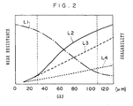
Fig. 2 is a characteristic diagram of a reverse flow preventing
device.
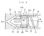
Fig. 3 is a cross-sectional view showing main portions of an
injection device in a second embodiment of the present invention.
DETAILED DESCRIPTION OF THE INVENTION
Hereinafter, embodiments of the present invention will be
described in detail with reference to the drawings.
Fig. 1 is a cross-sectional view showing main portions of
an injection device in a first embodiment of the present invention.
Fig. 2 is a characteristic diagram of a reverse flow preventing
device. In Fig. 2, the gap is on the horizontal axis, and the wear
resistance and sealability are on the vertical axis.
In Fig. 1, reference numeral 11 is a heating cylinder serving
as a cylinder member. The heating cylinder 11 has an injection
nozzle 21 at the front end portion thereof (the left end portion
in Fig. 1). A nozzle opening 21a is formed at the front end (the
left end in Fig. 1) of the injection nozzle 21. Further, reference
numeral 12 is a screw which serves as an injecting member and is
disposed so as to be freely rotatable and so as to be able to freely
advance and withdraw, within the heating cylinder 11. The screw
12 has a screw main body 13, and a screw head 14 which is mounted
to the front end of the screw main body 13.
A spiral flight 15 is formed at the outer peripheral surface
of the screw main body 13. A groove 16 is formed along the flight
15. Further, the screw head 14 has a distal end portion 17 which
is formed in a substantially conical configuration, and a small
diameter portion 18 which is circular and which is formed integrally
with the rear (the right side in Fig. 1) of the distal end portion 17
and whose diameter is smaller than that of the distal end portion
17 . Grooves 19, which are for the passage of an unillustrated resin
which serves as a molding material, are formed so as to extend
along the axial direction at plural places (four places in the
present embodiment) in the circumferential direction of the distal
end portion 17.
A co-rotating type reverse flow preventing ring 23, which is
cylindrical and is for preventing the resin from flowing reversely,
is disposed at the periphery of the small diameter portion 18 so
as to be able to move freely in the axial direction with respect
to the screw head 14. An annular flow path 24 is formed between
the small diameter portion 18 and the reverse flow preventing ring
23. A gap G is formed between the outer peripheral surface of the
reverse flow preventing ring 23 and the surface of the heating
cylinder 11, i.e., the inner peripheral surface of the heating
cylinder 11. The gap G is the difference in the radial direction
dimensions of these two members, i . e. , the difference between the
radius of the reverse flow preventing ring 23 and the radius of
the heating cylinder 11. Further, the reverse flow preventing ring
23 has a main body portion 25 positioned at the outer periphery
of the small diameter portion 18, and claws 26 which are formed
so as to project forward (toward the left in Fig. 1) from the main
body portion 25 and which serve as anchor portions which anchor
with the grooves 19. Accordingly, the reverse flow preventing
ring 23 is rotated as the screw 12 is rotated.
Note that, in the present embodiment, four of the claws 26 are
provided, and the claws 26 anchor with the grooves 19 respectively.
However, it suffices to provide at least one claw 26.
In the injection device having the above-described structure,
an unillustrated motor for metering, which serves as a
first driving portion, is provided in order to rotate the screw
12, and an unillustrated motor for injection, which serves as a
second driving portion, is provided in order to make the screw
12 advance and withdraw (i.e., in order to move the screw 12 toward
the left and the right in Fig. 1).
In the metering process, when a metering processing means
of an unillustrated control section carries out metering
processing and the motor for metering is driven, the screw 12 is
rotated, and resin is supplied from an unillustrated hopper which
is disposed at a predetermined place at the heating cylinder 11.
This resin is heated and melted by the heating cylinder 11, and
is moved forward through the groove 16, and passes through the
flow path 24 and the grooves 19, and is stored in front of the
screw head 14 . Accompanying this, the screw 12 is withdrawn rearward
(moved to the right in Fig. 1).
Next, in the injecting process, when an injection processing
means of the control section carries out injection processing and
the motor for injection is driven, the screw 12 is advanced forward
(moved to the left in Fig. 1). The resin stored in front of the
screw head 14 is injected out from the injection nozzle 21, and
is filled into the cavity of an unillustrated mold device.
At the time of injecting the resin, a portion of the resin
stored in front of the screw head 14 attempts to reversely flow
rearward via the groove 16 of the screw 12, the space between the
outer peripheral surface of the screw 12 and the inner peripheral
surface of the heating cylinder 11, and the like. Here, the reverse
flow preventing device is provided, and prevents the portion of
the resin stored in front of the screw head 14 from reversely
flowing rearward.
To this end, the reverse flow preventing device is formed
from a sealing portion 31 formed at the front end portion of the
screw main body 13, the screw head 14, the reverse flow preventing
ring 23, and the like. The sealing portion 31 has a first sealing
surface 31a which is formed at an incline so as to be tilted rearward
from the central side toward the radial direction outer side. The
reverse flow preventing ring 23 has, at the rear end thereof, a
second sealing surface 25a formed so as to correspond to the first
sealing surface 31a.
Accordingly, in the injecting process, when the screw 12 is
advanced forward, the reverse flow preventing ring 23 is pushed
rearward by the pressure of the resin in front of the screw head
14, and the first and second sealing surfaces 31a, 25a are brought
into close contact with one another. Accordingly, the resin within
the flow path 24 does not flow toward the screw main body 13 side.
Therefore, it is possible to prevent the portion of the resin stored
in front of the screw head 14 from attempting to reversely flow
rearward.
As shown in the present embodiment, when the co-rotating type
reverse flow preventing ring 23 is used, the reverse flow preventing
ring 23 is rotated accompanying the rotation of the screw 12.
Therefore, the reverse flow preventing ring 23, while rotating,
contacts the heating cylinder 11, and the outer peripheral surface
of the reverse flow preventing ring 23 and the inner peripheral
surface of the heating cylinder 11 are sliding surfaces which slide
against one another. When wear arises at the outer peripheral surface
of the reverse flow preventing ring 23 and the inner peripheral
surface of the heating cylinder 11, the durabilities of the reverse
flow preventing device and the heating cylinder 11 deteriorate.
In particular, when molding is carried out by using a resin
which contains silicone, the greater the silicone content, the
faster the progression of wear. Further, when the silicone precipitates
from the resin, the lubricating layer formed by the resin
becomes thin, and the progression of wear becomes even faster.
Thus, it has been thought to slow the progression of wear
by making the gap G large. However, when the gap G becomes large,
when the screw 12 is advanced forward in the injecting process,
the amount of resin which reversely flows rearward increases. As
a result, the amount of resin filled in the cavity becomes unstable,
and the quality of the molded product deteriorates.
Therefore, in the present embodiment, boron carbide
(tetraboron carbide: B4C), which serves as a covering film (a hard
covering film) formed of a material having high wear resistance,
is covered by vapor deposition on the surface of the reverse flow
preventing ring 23. Note that, at the reverse flow preventing ring
23, in order to make the surface of the steel material which is
the base material corrosion-resistant, it is preferable to form
a chromium (Cr) layer as an intermediate layer, and to cover the
boron carbide on the surface of the chromium layer. Moreover,
although it is preferable that the boron carbide be covered only
on the surface of the reverse flow preventing ring 23, the boron
carbide may be covered on the inner peripheral surface of the heating
cylinder 11. Or, the surface of the reverse flow preventing ring
23 and the inner peripheral surface of the heating cylinder 11
may be covered with boron carbide.
As shown in Table 1, boron carbide has a low coefficient of
friction as compared with other highly wear-resistant materials
such as titanium nitride (TiN), and has high hardness (Vickers
hardness) as compared with titanium nitride (TiN), chromium
nitride (CrN) and the like. Therefore, the progress of wear can
be slowed. Moreover, because the temperature of the vapor
deposition for forming the covering film is low, the adhesion with
the steel material, the chromium layer, and the like is good. It
is difficult for the boron carbide to be peeled off from the steel
material, the chromium layer and the like, and in addition, it
is difficult for the boron carbide to be affected by deformation.
Note that when the chromium layer is used as an intermediate layer,
it is even more difficult for the boron carbide to be peeled off
because the chromium binds together well with the steel material
and the boron carbide. A titanium (Ti) layer, a silicone layer,
or the like can be used as an intermediate layer which can bind
together well with the steel material and the boron carbide.
| | coefficient of friction | Vickers hardness [Hv] | vapor deposition temperature [°C] |
| boron carbide (B4C) | 0.2 - 0.3 | 2600 - 2800 | < 120 |
| titaniumnitride (TiN) | 0.3 - 0.5 | 2000 - 2300 | 480 - 510 |
| chromiumnitride (CrN) | 0.2 - 0.3 | 1500 - 1800 | 400 - 500 |
When the gap G is varied, the smaller the gap G, the greater
the sealability, and the easier it is to prevent the portion of
the resin stored in front of the screw head 14 from reversely flowing
rearward. In contrast, the greater the gap G, the worse the
sealability, and the harder it is to prevent the portion of the
resin stored in front of the screw head 14 from reversely flowing
rearward.
Moreover, the smaller the gap G, the greater the friction,
and therefore, the lower the wear resistance, and the easier it
is for wear to arise. In contrast, the larger the gap G, the less
the friction, and therefore, the higher the wear resistance, and
the more difficult it is for wear to arise.
Here, a comparison of the sealability, andthewear resistances
of steel, boron carbide, and titanium nitride and chromium nitride
at the time when the gap G is varied is shown in Fig. 2. In Fig.
2, L1 is a line showing sealablity, L2 is a line showing the wear
resistanceofboroncarbide, L3isalineshowingthewearresistances
of titanium nitride and chromium nitride, and L4 is a line showing
the wear resistance of steel.
As shown in Fig. 2, it can be seen that, in the case of boron
carbide, when the gap G is greater than or equal to 30 µm, the
wear resistance is markedly higher than those of steel and titanium
nitride and chromium nitride. Accordingly, it is preferable to
cover the surface of the reverse flow preventing ring 23 and the
inner peripheral surface of the heating cylinder 11 with boron
carbide, and to make the gap G greater than or equal to 30 µm.
Note that, when the gap G is larger than 110 µm, the sealability
is low. Therefore, it is preferable that the gap G is less than
or equal to 110 µm.
In this way, when the surface of the reverse flow preventing
ring 23 and the inner peripheral surface of the heating cylinder
11 are covered by boron carbide and the gap G is greater than or
equal to 30 µm and less than or equal to 110 µm, even if the reverse
flow preventing ring 23, while rotating, contacts the heating
cylinder 11, it is difficult for wear to arise at the outer peripheral
surface of the reverse flow preventing ring 23 and the inner
peripheral surface of the heating cylinder 11, and the durabilities
of the reverse flow preventing device and the heating cylinder
11 can be improved.
Moreover, when molding is carried out by using a resin which
contains silicone, even if the silicone content is large, and the
silicone precipitates from the resin, and the lubricating layer
formed by the resin becomes thin, and it becomes easy for the reverse
flow preventing ring 23 and the heating cylinder 11 to contact
one another, it is possible to prevent wear from arising because
the coefficient of friction of the boron carbide is low.
Further, because there is no need to make the gap G large,
when the screw 12 is advanced forward during the inj ecting process,
the amount of resin which reversely flows rearward is not large,
and the amount of resin which is filled into the cavity can be
stabilized. Accordingly, the quality of the molded product can
be improved.
Moreover, boron carbide is coveredon the surface of the reverse
flow preventing ring 23, whereas the inner peripheral surface of
the heating cylinder 11 is subjected to a nitriding treatment such
that steel nitride is formed in a vicinity of the inner peripheral
surface of the heating cylinder 11. Inthiscase, theVickershardness
of the boron carbide is 2600 to 2800 Hv, whereas the Vickers hardness
of the steel nitride is 1000 Hv or less. A sufficient difference
in hardness is formed between the outer peripheral surface of the
reverse flow preventing ring 23 and the inner peripheral surface
of the heating cylinder 11.
Accordingly, the coefficient of friction between the reverse
flow preventing ring 23 and the heating cylinder 11 can be made
small. Therefore, not only is it possible to sufficiently prevent
the occurrence of wear between the outer peripheral surface of the
reverse flow preventing ring 23 and the inner peripheral surface
of the heating cylinder 11, but also, it is possible to prevent
scoring from occurring when the screw 12 is advanced forward.
Moreover, accompanying the increase in wear resistance due
to the boron carbide, the peelability can be improved. Therefore,
it is possible to prevent resin and the like from adhering to the
surface. Accordingly, the occurrence of resin scorching can be
prevented.
Next, a second embodiment of the present invention will be
described. Structures which are the same as those of the first
embodiment are denoted by the same reference numerals, and
description thereof is omitted.
Fig. 3 is a cross-sectional view showing main portions of
an injection device in the second embodiment of the present
invention.
In this case, in the metering process, when the metering processing
means of the unillustrated control section carries out
metering processing and the unillustrated motor for metering is
driven, the screw 12, which serves as an injecting member, is
rotated, and resin, which is not illustrated and which serves as
a molding material, is supplied from the unillustrated hopper which
is disposed at a predetermined place at the heating cylinder 11.
This resin is heated and melted by the heating cylinder 11, and
is moved forward (toward the left in the figure) through the groove
16, and passes through the flow path 24 and the grooves 19, and
is stored in front of the screw head 14. Accompanying this, the
screw 12 is withdrawn rearward (moved to the left in the figure) .
Next, in the injecting process, when the injection processing
means of the control section carries out injection processing and
the unillustrated motor for injection is driven, the screw 12 is
advanced forward (moved to the right in the figure). The resin
stored in front of the screw head 14 is injected out from the
injection nozzle 21, and is filled into the cavity of the
unillustrated mold device.
The reverse flow preventing device is provided in order to
prevent the portion of the resin stored in front of the screw head
14 from reversely flowing rearward (toward the right in the figure) .
The reverse flow preventing device is formed from the sealing
portion 31 formed at the front end portion (the left end portion
in the figure) of the screw main body 13, the distal end portion
17, a reverse flow preventing ring 35, and the like. The sealing
portion 31 has the first sealing surface 31a which is formed at
an incline so as to be tilted rearward from the central side toward
the radial direction outer side. The reverse flow preventing ring
35 has, at the rear end (the right end in the figure) thereof,
a second sealing surface 35a formed so as to correspond to the
first sealing surface 31a.
Accordingly, in the injecting process, when the screw 12 is
advanced forward, the reverse flow preventing ring 35 is pushed
rearward by the pressure of the resin in front of the distal end
portion 17, and the first and second sealing surfaces 31a, 35a
are brought into close contact with one another. As a result, the
resin within the flow path 24 does not flow toward the screw main
body 13 side. Therefore, it is possible to prevent the portion
of the resin stored in front of the screw head 14 from attempting
to reversely flow rearward.
As shown in the present embodiment, when the non-co-rotating
type reverse flow preventing ring 35 is used, the reverse flow
preventing ring 35 is completely independent of the screw head
14, and is not rotated accompanying the rotation of the screw 12.
Thus, the occurrence of wear at the outer peripheral surface of
the reverse flow preventing ring 35 and the inner peripheral
surface of the heating cylinder 11 is suppressed.
In the metering process, when the screw 12 is withdrawn rearward
as the screw 12 is rotated and the resin is stored in front of
the screw head 14, the reverse flow preventing ring 35 is moved
forward relative to the screw 12, and is pushed against the screw
head 14. In this case, the screw 12 rotates, whereas the reverse
flow preventing ring 35 is not rotated. Therefore, the screw head
14 and the reverse flow preventing ring 35 slide against one another,
and wear arises at the rear end surface of the screw head 14 (the
right end surface in the figure) and the front end surface of the
reverse flow preventing ring 35 (the left end surface in the
figure). Note that the screw head 14 has, at the rear end thereof,
a first sliding surface 17a which is formed at an incline so as
to be tilted forward from the central side toward the radial
direction outer side. The reverse flow preventing ring 35 has,
at the front end (the left end in the figure) thereof, a second
sliding surface 35b formed so as to correspond to the first sliding
surface 17a.
Here, boron carbide, which serves as a covering film (a hard
covering film) formed of a material having high wear resistance,
is covered by vapor deposition on the surfaces of the reverse flow
preventing ring 35 and the screw head 14. Note that, at the reverse
flow preventing ring 35 and the screw head 14, in order to make
the surface of the steel material which is the base material
corrosion-resistant, it is preferable to form a chromium layer
as an intermediate layer, and to cover the boron carbide on the
surface of the chromium layer.
Accordingly, even if the screw head 14 and the reverse flow
preventing ring 35 slide against one another while the screw 12
is rotating, it is difficult for wear to arise at the second
sliding surface 35b of the reverse flow preventing ring 35 and
the first sliding surface 17a of the screw head 14, and the
durabilities of the reverse flow preventing device and the screw
head 14 are improved.
Note that it is preferable to cover the boron carbide only
on the surface of the reverse flow preventing ring 35. However,
the boron carbide may be covered on the surface of the screw head
14. Moreover, the boron carbide may be covered on the surfaces
of the reverse flow preventing ring 35 and the screw head 14.
Moreover, boron carbide is covered on the second sliding
surface 35b, whereas the first sliding surface 17a is subjected
to a nitriding treatment such that steel nitride is formed in a
vicinity of the first sliding surface 17a. In this case, the
Vickers hardness of the boron carbide is 2600 to 2800 Hv, whereas
the Vickers hardness of the steel nitride is 1000 Hv or less . A
sufficient difference in hardness is formed between the first and
second sliding surfaces 17a, 35b.
Accordingly, the coefficient of friction between the screw
head 14 and the reverse flow preventing ring 35 can be made small.
Therefore, the occurrence of wear at the first and second sliding
surfaces 17a, 35b can be sufficiently prevented.
Moreover, when molding is carried out by using a resin which
contains silicone, even if the silicone content is large, and the
silicone precipitates from the resin, and the lubricating layer
formed by the resin becomes thin, and it becomes easy for the screw
head 14 and the reverse flow preventing ring 35 to contact one
another, it is possible to prevent wear from arising.
EXAMPLE
Molding was carried out by using resin "H45H" (manufactured
by Toyo-Styrene Co., Ltd.) in an inj ection molding machine "SG180M"
(screw diameter: 40 mm) manufactured by Sumitomo Heavy Industries,
Ltd. The resin "H45H" contained 2% by mass of silicone "KF96H"
manufactured by Shin-Etsu Chemical Co. , Ltd. and 0.5% by mass of
carbon "#950" manufactured by Mitsubishi Chemical Corp.
Then, a multilayer structure of one chromium layer and two
boron layers including boron carbide "DB-1031J" manufactured by
Diamond Black Inc. was covered on the screw head and the reverse
flow preventing device used in the injection device of the "SG180M"
injection molding machine.
Note that the present invention is not limited to the
above-described Example, and various modifications can be carried
out on the basis of the gist of the present invention, and such
modifications are not to be excluded from the scope of the present
invention.
As described above, the injection device of the present
invention has a heating cylinder, and a screw disposed within the
heating cylinder so as to rotate freely and advance and withdraw
freely.
The screw has a screw main body; a screw head which is mounted
to a front end of the screw main body, and which has a distal end
portion and a small diameter portion; and a reverse flow preventing
ring which is disposed at a periphery of the small diameter portion
and which prevents a molding material from flowing reversely as
the screw is advanced forward. Boron carbide is covered on a surface
of at least one of the reverse flow preventing ring, the heating
cylinder, and the screw head. In this way, when the surface is
covered by boron carbide, it is difficult for wear to arise at
the outer peripheral surface of the reverse flow preventing ring
and the inner peripheral surface of the heating cylinder, and the
durabilities of the reverse flow preventing device and the heating
cylinder can be improved.
Moreover, when molding is carried out by using a resin which
contains silicone, even if the silicone content is large, and the
silicone precipitates from the resin, and the lubricating layer
formed by the resin becomes thin, wear can be prevented from arising.
In yet another injection device of the present invention,
a gap of about 30 µm to 110 µm is formed between an outer peripheral
surface of the reverse flow preventing ring and an inner peripheral
surface of the heating cylinder. Because of the gap of about 30
µm to 110 µm, when the screw is advanced forward during the injecting
process, the amount of resin which reversely flows rearward is
not large, and the amount of resin which is filled into the cavity
can be stabilized. Accordingly, the quality of the molded product
can be improved.
In still yet another inj ection device of the present invention,
a hardness of a sliding surface of the heating cylinder is lower
than a hardness of a sliding surface of the reverse flow preventing
ring. Accordingly, the coefficient of friction between the
reverse flow preventing ring and the heating cylinder can be made
small. Therefore, it is possible to sufficiently prevent the
occurrence of wear between the sliding surfaces.
In yet another injection device of the present invention,
a hardness of a sliding surface of the screw head is lower than
a hardness of a sliding surface of the reverse flow preventing
ring. Accordingly, the coefficient of friction between the
reverse flow preventing ring and the screw head can be made small.
Therefore, it is possible to sufficiently prevent the occurrence
of wear between the sliding surfaces.