EP1407546B1 - Reactance filter having an improved edge steepness - Google Patents
Reactance filter having an improved edge steepness Download PDFInfo
- Publication number
- EP1407546B1 EP1407546B1 EP02737839A EP02737839A EP1407546B1 EP 1407546 B1 EP1407546 B1 EP 1407546B1 EP 02737839 A EP02737839 A EP 02737839A EP 02737839 A EP02737839 A EP 02737839A EP 1407546 B1 EP1407546 B1 EP 1407546B1
- Authority
- EP
- European Patent Office
- Prior art keywords
- resonator
- branch
- resonators
- reactance filter
- filter according
- Prior art date
- Legal status (The legal status is an assumption and is not a legal conclusion. Google has not performed a legal analysis and makes no representation as to the accuracy of the status listed.)
- Expired - Lifetime
Links
Images


Classifications
-
- H—ELECTRICITY
- H03—ELECTRONIC CIRCUITRY
- H03H—IMPEDANCE NETWORKS, e.g. RESONANT CIRCUITS; RESONATORS
- H03H9/00—Networks comprising electromechanical or electro-acoustic devices; Electromechanical resonators
- H03H9/46—Filters
- H03H9/54—Filters comprising resonators of piezo-electric or electrostrictive material
- H03H9/58—Multiple crystal filters
- H03H9/60—Electric coupling means therefor
- H03H9/605—Electric coupling means therefor consisting of a ladder configuration
Definitions
- the invention relates to bulk wave filters (bulk acoustic wave filter or BAW filter called), which are constructed according to the Reaktanzfiltertex.
- reactance filters are for example also from the DE 196 38 451 A and the JP 63 253711 A known.
- a BAW resonator R exists according to FIG. 1a in its simplest embodiment of a thin film P of a piezoelectric material, which is provided on the top and bottom each with an electrode E1, E2. Ideally, this structure is surrounded by air on both sides of the electrode.
- an electric field acts on the piezoelectric layer, as a result of which the piezoelectric material converts part of the electrical energy into mechanical energy in the form of acoustic waves. These propagate parallel to the field direction as so-called bulk waves and are reflected at the electrode / air interfaces.
- f r which depends on the thickness of the piezoelectric layer or on the thickness of the volume oscillator, the resonator shows a resonance and thus behaves like an electrical resonator.
- the BAW resonator R consists of a series resonance circuit of dynamic inductance L1, dynamic capacitance C1 and a dynamic resistance R1, as well as a static connected in parallel thereto Capacitance C0 of the BAW resonator.
- the series resonance circuit reproduces the behavior of the resonator in the case of resonance, ie in the region of the resonance frequency f r .
- the static capacitance C0 reflects the behavior in the range f «f r and f r » f.
- the dynamic capacitance C1 is proportional to the static capacitance C0 of the BAW resonator.
- a reactance filter is made according to FIG. 7 of at least one basic element which has a series-connected resonator R2 with a resonant frequency f rs and associated antiresonant frequency f as and a second resonator R1 connected in parallel with a second terminal, in particular parallel to the ground, with a resonant frequency f rp and associated antiresonant frequency f ap .
- a filter with bandpass behavior and a center frequency f 0 the following relationship applies to the two resonators in the serial or parallel branch: f ap ⁇ f rs ⁇ f 0
- FIG. 16a shows the course of the impedance Zs of the serial resonator and the admittance Yp of the parallel resonator over the frequency f.
- FIG. 16b shows the transmission behavior of a filter consisting of a basic element, the resonance frequencies of which FIG. 16a are selected.
- FIG. 7 shows a basic member, in principle as a two-port with the terminals 3 - 1 and 3 - 2 (Tor 1) and the terminals 3 - 3 and 3, respectively - 4 of Tor 2 is to be considered.
- the connection 3 - 1 is the input and the connection 3 - 3 the output of the series resonator.
- the input of the parallel resonator is connected to the connection 3 - 1.
- the terminals 3 - 2 and 3 - 4 represent the reference ground in an asymmetrical operation.
- the output of the parallel resonator 3 - 5, which faces the reference ground, is hereinafter referred to as the output or ground side of the parallel resonator.
- the inductance L ser which lies between the output side of the parallel resonator and the reference ground, reflects the connection to the housing ground in the real structure again.
- Resonators of the same type (series resonator or parallel resonator) arranged directly one after the other in a circuit of a reactance filter can also be combined to form a resonator, the overall capacitive effect of the combined resonator remaining the same.
- the curve 1 in FIG. 6 shows the transmission behavior of a reactance filter, which is composed of uniform BAW resonators, each having a relatively large ratio of dynamic to static capacity. The individual resonators therefore have a relatively large bandwidth.
- Curve 2 is the transmission curve of a corresponding reactance filter of resonators with a small ratio of dynamic to static capacitance and therefore relatively low bandwidth of the single resonators. In the first case (curve 1) one obtains a bandpass filter with high bandwidth and low edge steepness, in the second case (curve 2) one obtains a bandpass filter with lower bandwidth and high edge steepness.
- a further possibility for broadening a steep-edged filter consists in a reduction of the ratio (C 0p / C 0s ) of static capacitance C0 p in the parallel branch and static capacitance C0s in the series branch.
- the bandwidth can be increased to some extent without losing the self-adaptation and the associated low losses.
- the selection level of the BAW reactance filter is greatly reduced, so that the filter can no longer fulfill possible selection requirements and, for example, can no longer adequately damp unwanted frequencies.
- the invention takes advantage of this and indicates a reactance filter constructed of BAW-type resonators. It comprises at least one basic element with a first resonator in a first branch and a second resonator in a second one Branch, which are connected in parallel with each other, wherein one of the branches is the serial branch, while the other branch is a parallel branch.
- the reactance filter according to the invention has a transmission behavior with an improved because steeper edge.
- the other edge and the other resonator and filter properties remain unaffected. If, for example, in the case of a resonator in the serial branch, the ratio V c is reduced compared with the corresponding ratio V c in the resonator of the parallel branch, the right flank of the passband is set steeper, that is to say the flank delimiting the passband from higher frequencies.
- a passband having a steeper left slope is obtained.
- the right edge of the passband is determined by the characteristics of the serial resonator.
- the steepness of the right flank can be seen from how quickly the impedance curve of the serial resonator increases from the resonant frequency to the anti-resonant frequency.
- a steeper impedance increase in a (serial) resonator is obtained when the distance between resonant and anti-resonant frequencies of the resonator is reduced.
- a reactance filter Since a real reactance filter is generally obtained by connecting a plurality of base elements, a reactance filter usually has a plurality of series resonators and a plurality of parallel resonators.
- a reactance filter according to the invention is already obtained when said changes are made in a single resonator of one type (serial or parallel).
- a further improved even steeper edge is obtained if a plurality of resonators of one type, preferably all resonators of one type have a smaller distance between resonant and anti-resonant frequencies. Due to the given dependence of the corresponding quantities on each other, this distance increases with the said ratio V c of the dynamic to the static capacity.
- a resonator having such a reduced pitch will be referred to as a narrow band resonator hereinafter.
- a resonator with a correspondingly greater distance from the resonance and anti-resonance frequency is referred to as a broadband resonator.
- the broadbandity of the filter that is, the width of the passband is achieved regardless of the use of at least one narrow-band resonator for a first branch characterized in that broadband resonators are used in the second branch.
- a filter according to the invention having, for example, an improved steeper left flank is achieved by narrow-band parallel resonators which as a result achieve a high selection at frequencies which are slightly lower than the lowest frequency of the pass band of the filter.
- filters are preferably used as filters in the receive path of the current GSM or CDMA-based mobile radio systems, which must provide a high suppression of the transmission band.
- K 2 eff ⁇ / 2 2 x fa - Fri. fa
- K 2 eff ⁇ / 2 2 x fa - Fri. fa
- a narrow band resonator can be realized on a suitable piezoelectric material with a lower effective electromechanical coupling coefficient.
- This effective electromechanical coupling coefficient is obtained from the sum of the effective couplings of all the modes propagatable in a piezoelectric material.
- the effective coupling (for the used mode) can be determined from the equivalent circuit diagram of a BAW resonator according to the following formula: k 2 eff ⁇ C ⁇ 1 C 1 + C 0
- a reactance filter according to the invention therefore has, for example, resonators with a higher coupling piezo material in the series branch of the reactance filter, whereas resonators with lower coupling piezo material have the same branch in the same branch.
- Such a filter then has a high steepness of the left flank.
- the reactance filter according to the invention retains a high bandwidth, which is ensured by the relatively high separation of resonance frequencies and anti-resonance frequency in the series resonators.
- the effective coupling can also be reduced in a reactance filter with BAW resonators by inserting an additional layer of non-piezoelectric material between the two electrodes of a BAW resonator.
- the coupling coefficient is thereby reduced by the proportion which the layer of the non-piezoelectric material has at the ratio of the layer thickness of the non-piezoelectric material to the total layer thickness of the resonator.
- a reduction of the effective coupling is obtained, which for the filter or the resonator is equivalent to a reduction of the ratio V c and thus also equivalent to a reduction the distance of resonance and anti-resonant frequency is.
- a reactance filter according to the invention therefore has, for example, resonators which use in a first branch an electrode material which differs from the electrode material of the resonators in the second branch.
- a reactance filter with resonators with tungsten electrodes in a first branch and resonators with aluminum electrodes in a second branch accordingly has a narrowband resonator in the second branch. If the second branch is a parallel branch, the left edge of the passband of the reactance filter is improved. If the corresponding narrowband resonator is used in the serial branch, the right flank is improved in the reactance filter.
- a BAW resonator is preferably surrounded by air on both sides of the electrodes.
- two contact points far away from one another are provided for an electrode layer, this being referred to as so-called bridge resonators.
- the acoustic wave is reflected on both sides of the resonator at the solid-air interface. It is also possible, however, one BAW resonator in such a way that one of the electrodes over the entire surface rests on a substrate.
- the reflection of the acoustic wave can then be ensured with an acoustic mirror, which can be realized for example by two layers of different acoustic impedance, each having a layer thickness of ⁇ / 4 with respect to the wavelength ⁇ of the acoustic wave within the layer material.
- the repeated reflections at the junctions of two layers with very different acoustic impedances then lead to extinction of the wave components reflected at different boundary surfaces, which in turn means a high reflection for the mirror.
- a reactance filter according to the invention therefore has Bridgeresonators, for example, in the parallel branch, whereas resonators with an acoustic mirror are provided in the serial branch, wherein a transmission characteristic with a passband steeper in the right flank is obtained.
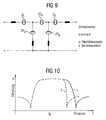
- FIG. 7 shows a basic element which is constructed from a first resonator R1 in a parallel branch and a second resonator R2 in a serial branch. Ports 3-1 and 3-2 form the filter input, ports 3-3 and 3-4 the filter output.
- the parallel branch or the resonator R1 in the parallel branch is connected via a series inductance L ser , formed from the sum of the inductances of the terminal to the housing ground, to the terminals 3-2 and 3-4 respectively.
- the resonator is formed R1 with a piezoelectric layer of zinc oxide having an electromechanical coupling constant K 2 eff 1 and the resonator R2 with a piezoelectric layer p of aluminum nitride having a piezoelectric coupling constant K 2 eff 2 in this embodiment, where K 2 eff 1> K 2 eff 2.
- K 2 eff 1> K 2 eff 2 the resonance frequencies and thus also the Antiresonanzfrequenzen the two resonators R1 and R2 are adjusted so that the resonance frequency of R2 is approximately equal to the anti-resonant frequency of R1.
- the transmission curve 2 in FIG. 10 shows the damping behavior of a reactance filter according to the invention according to this embodiment, which is compared with the transmission curve 1 of a conventional reactance filter, in which both resonators use zinc oxide for the piezoelectric layer p of the resonators. It turns out that the right flank of the curve 2 is set much steeper than that of the known filter. The bandwidth of the overall filter is only marginally reduced.
- FIG. 12 shows the influence of the electrode material on the impedance behavior of a resonator.
- Curves 3 and 4 show the impedance behavior according to FIG. 1 formed resonator, wherein curve 3 represents the impedance of a resonator with aluminum electrodes, the curve 4, however, the impedance behavior of a resonator with tungsten electrodes. It can be seen that the greater effective coupling of tungsten electrodes according to curve 4 results in a higher distance of the resonant frequency from the anti-resonant frequency.
- FIG. 15 shows a resonator, which is arranged with the aid of an acoustic mirror AS on a substrate S.
- a reactance filter according to the invention will now consist of at least one basic element (for example according to FIG. 7 ), wherein in a first branch resonators in Bridgebau way, in a second branch, however, resonators are used with acoustic mirror. Since the effective coupling coefficient for resonators according to FIG. 14 is greater than resonators according to FIG. 15 , the flank of the passband which is associated with the armature with the acoustic mirrors can be made steeper. For example, if the resonators R1 are implemented with acoustic mirrors, the resonators R2 as Bridgeresonatoren, a steeper left flank is obtained in the transmission behavior of the reactance filter thus constructed.
Description
Die Erfindung betrifft Volumenwellenfilter (bulk acustic wave filter oder auch BAW-Filter genannt), die nach dem Reaktanzfilterprinzip aufgebaut sind.The invention relates to bulk wave filters (bulk acoustic wave filter or BAW filter called), which are constructed according to the Reaktanzfilterprinzip.
Aus einem Artikel
Weitere Reaktanzfilter sind beispielsweise auch aus der
Ein BAW-Resonator R besteht gemäß
Im Ersatzschaltbild gemäß ![]()
![]()
Für die Resonanzfrequenz fr und die Antiresonanzfrequenz fa eines BAW-Resonators gelten: 

Ein Reaktanzfilter besteht gemäß ![]()
![]()
Das Selektionsniveau eines aus BAW-Resonatoren aufgebauten Reaktanzfilters wird zum einen durch das Verhältnis C0p / C0s aus statischer Kapazität C0p im Parallelzweig und statischer Kapazität C0s im Serienzweig bestimmt, zum anderen durch die Anzahl der kaskadierten, also der miteinander in Reihe geschalteten Grundglieder.The selection level of a reactance filter constructed from BAW resonators is determined on the one hand by the ratio C0 p / C0 s of static capacitance C0 p in the parallel branch and static capacitance C0 s in the series branch, on the other hand by the number of cascaded, ie connected in series phalanges.
Mehrere Grundglieder können angepaßt miteinander verschaltet werden, wobei die Struktur zweiter benachbarter Grundglieder jeweils gespiegelt ist. Dann ist die Ausgangsimpedanz des ersten Grundglieds (7-1 in
Unmittelbar in einer Verschaltung eines Reaktanzfilters hintereinander liegende Resonatoren gleichen Typs (Serienresonator oder Parallelresonator) können auch jeweils zu einem Resonator zusammengefaßt werden, wobei die kapazitive Gesamtwirkung des zusammengefaßten Resonators gleichbleibt.Resonators of the same type (series resonator or parallel resonator) arranged directly one after the other in a circuit of a reactance filter can also be combined to form a resonator, the overall capacitive effect of the combined resonator remaining the same.
Aus den Formeln (1.2) bis (1.4) ist ersichtlich, daß sowohl die maximal erreichbare Bandbreite als auch die Steilheit der Flanken eines solchen Reaktanzfilters von der Differenz aus Resonanz- und Antiresonanzfrequenz der einzelnen Resonatoren abhängt. Diese Differenz wiederum ergibt sich aus dem Verhältnis von dynamischer Kapazität C1 und statischer Kapazität C0. Da diese Kapazitäten zueinander proportional sind, ändert sich das Kapazitätsverhältnis C1/C0 durch eine Änderung einer dieser Kapazitäten nicht. Beispielsweise könnte C0 durch Änderung der Größe des Resonators variiert werden. In der Regel haben alle Resonatoren eines Reaktanzfilters die gleiche relative Bandbreite (fa - fr)/f0.From the formulas (1.2) to (1.4) it can be seen that both the maximum achievable bandwidth and the steepness of the Flanks of such a reactance filter on the difference of resonance and anti-resonant frequency of the individual resonators depends. This difference, in turn, results from the ratio of dynamic capacitance C1 and static capacitance C0. Since these capacitances are proportional to each other, the capacitance ratio C1 / C0 does not change by changing one of these capacitances. For example, C0 could be varied by changing the size of the resonator. As a rule, all resonators of a reactance filter have the same relative bandwidth (fa-fr) / f0.
Die Kurve 1 in
Versucht man nun, bei einem solchen steilflankigen Filter, die Bandbreite auf das Niveau desjenigen Filters mit dem größeren Kapazitätsverhältnis zu erhöhen, indem man die Mittenfrequenzen von Serienresonatoren erhöht und/oder die Mittenfrequenz der Parallelresonatoren verringert, erhält man in der Mitte des Paßbandes eine starke Fehlanpassung, da nunmehr fap << frs. Damit ist die Bedingung (1.4) nicht mehr erfüllt. Daher steigen auch die Verluste in der Mitte des Paßbandes stärker an.If one tries to increase the bandwidth to the level of that filter with the larger capacitance ratio by increasing the center frequencies of series resonators and / or reducing the center frequency of the parallel resonators with such a steep-edged filter, a strong mismatch is obtained in the middle of the passband since now ap f << f rs. Thus, condition (1.4) is no longer satisfied. Therefore, the losses increase more in the middle of Paßbandes.
Eine weitere Möglichkeit zur Verbreiterung eines steilflankigen Filters besteht in einer Verkleinerung des Verhältnisses (C0p/C0s) von statischer Kapazität C0p im Parallelzweig und statischer Kapazität C0s im Serienzweig. Dadurch kann die Bandbreite in einem gewissem Maße vergrößert werden, ohne die Selbstanpassung und die damit verbundenen geringen Verluste zu verlieren. Mit dieser Maßnahme wird aber das Selektionsniveau des BAW-Reaktanzfilters stark reduziert, so daß das Filter mögliche Selektionsanforderungen nicht mehr erfüllen kann und unerwünschte Frequenzen beispielsweise nicht mehr ausreichend abdämpfen kann.A further possibility for broadening a steep-edged filter consists in a reduction of the ratio (C 0p / C 0s ) of static capacitance C0 p in the parallel branch and static capacitance C0s in the series branch. As a result, the bandwidth can be increased to some extent without losing the self-adaptation and the associated low losses. With this measure, however, the selection level of the BAW reactance filter is greatly reduced, so that the filter can no longer fulfill possible selection requirements and, for example, can no longer adequately damp unwanted frequencies.
Aufgabe der vorliegenden Erfindung ist es daher, ein aus BAW-Resonatoren aufgebautes Reaktanzfilter anzugeben, welches eine verbesserte Flankensteilheit bei ausreichender Bandbreite aufweist, ohne daß dazu eine zusätzliche Anpassung oder eine Reduktion des Selektionsniveaus aufgenommen werden muß.It is therefore an object of the present invention to specify a reactance filter constructed from BAW resonators, which has an improved edge steepness with sufficient bandwidth, without the need for an additional adaptation or a reduction of the selection level.
Diese Aufgabe wird erfindungsgemäß durch ein Reaktanzfilter mit den Merkmalen von Anspruch 1 gelöst.This object is achieved by a reactance filter with the features of
Vorteilhafte Ausgestaltungen der Erfindung sowie bevorzugte Anwendungen der Erfindung sind weiteren Ansprüchen zu entnehmen.Advantageous embodiments of the invention and preferred applications of the invention can be found in further claims.
Die Erfindung nutzt die Tatsache, daß für die HF-Filter in vielen Mobilfunksystemen hohe Anforderungen an die Bandabgrenzung jeweils nur zum entsprechenden anderen Duplexband erforderlich sind. D. h., ein HF-Filter benötigt in der Regel nur auf der Seite des Paßbandes eine steile Flanke, die dem anderen Duplexband zugewandt ist. Bei den augenblicklich gängigen Mobilfunksystemen auf der Basis von GSM, CDMA, AMPS oder TDMA ist dies im Falle eines Empfangsfilters die linke Flanke, im Falle eines Sendefilters hingegen die rechte Flanke.The invention makes use of the fact that for the RF filters in many mobile radio systems high demands on the band demarcation in each case only to the corresponding other duplex band are required. That is, an RF filter usually requires only on the side of the Paßbandes a steep edge, which faces the other duplex tape. In the case of currently available mobile radio systems based on GSM, CDMA, AMPS or TDMA, this is the left flank in the case of a receive filter, but the right flank in the case of a transmit filter.
Die Erfindung macht sich dies zunutze und gibt ein Reaktanzfilter an, das aus Resonatoren vom BAW-Typ aufgebaut ist. Es umfaßt zumindest ein Grundglied mit einem ersten Resonator in einem ersten Zweig und einem zweiten Resonator in einem zweiten Zweig, die parallel zueinander geschalten sind, wobei einer der Zweige der serielle Zweig, der andere Zweig dagegen ein paralleler Zweig ist. Jeder der Resonatoren weist ein spezifisches Verhältnis Vc von dynamischer Kapazität C1 zu statischer Kapazität C0 auf: ![]()
wobei erfindungsgemäß das Verhältnis Vc für den Resonator eines ersten Zweigs niedriger eingestellt ist als für den Resonator des zweiten Zweigs. In Abhängigkeit davon, in welchem Zweig das Verhältnis Vc niedriger eingestellt wird, weist das erfindungsgemäße Reaktanzfilter ein Durchlaßverhalten mit einer verbesserten weil steileren Flanke auf. Die andere Flanke sowie die übrigen Resonator- und Filtereigenschaften bleiben davon unberührt. Wird beispielsweise bei einem Resonator im seriellen Zweig das Verhältnis Vc gegenüber dem entsprechenden Verhältnis Vc beim Resonator des parallelen Zweigs verringert, so wird die rechte Flanke des Paßbandes steiler eingestellt, also die Flanke, die das Paßband gegenüber höheren Frequenzen abgrenzt. Analog dazu wird bei einem Reaktanzfilter, bei dem der Resonator im parallelen Zweig ein kleineres Verhältnis Vc aufweist als der Resonator im seriellen Zweig, ein Paßband mit einer steiler eingestellten linken Flanke erhalten. Da in einem Grundglied eines Reaktanzfilters die Resonanz- und Antiresonanzfrequenzen des parallelen Resonators niedriger liegen als die entsprechenden Frequenzen des seriellen Resonators, wird beispielsweise die rechte Flanke des Paßbandes durch die Eigenschaften des seriellen Resonators bestimmt. Die Steilheit der rechten Flanke ist daran zu ersehen, wie schnell die Impedanzkurve des seriellen Resonators von der Resonanzfrequenz zur Antiresonanzfrequenz hin ansteigt. Ein steilerer Impedanzanstieg in einem (seriellen) Resonator wird erhalten, wenn der Abstand zwischen Resonanz- und Antiresonanzfrequenz des Resonators verringert wird. Da umgekehrt die Steilheit der linken Flanke im wesentlichen von dem Parallelresonator bzw. dem Resonator im Parallelzweig bestimmt wird, gelingt eine steilere Einstellung der linken Flanke durch eine Verringerung des Abstandes von Resonanz- und Antiresonanzfrequenz des Parallelresonators.The invention takes advantage of this and indicates a reactance filter constructed of BAW-type resonators. It comprises at least one basic element with a first resonator in a first branch and a second resonator in a second one Branch, which are connected in parallel with each other, wherein one of the branches is the serial branch, while the other branch is a parallel branch. Each of the resonators has a specific ratio V c of dynamic capacity C 1 to static capacity C 0 : ![]()
wherein according to the invention, the ratio V c for the resonator of a first branch is set lower than for the resonator of the second branch. Depending on in which branch the ratio V c is set lower, the reactance filter according to the invention has a transmission behavior with an improved because steeper edge. The other edge and the other resonator and filter properties remain unaffected. If, for example, in the case of a resonator in the serial branch, the ratio V c is reduced compared with the corresponding ratio V c in the resonator of the parallel branch, the right flank of the passband is set steeper, that is to say the flank delimiting the passband from higher frequencies. Similarly, in a reactance filter in which the resonator in the parallel branch has a smaller ratio V c than the resonator in the serial branch, a passband having a steeper left slope is obtained. For example, in a fundamental element of a reactance filter, since the resonant and antiresonant frequencies of the parallel resonator are lower than the corresponding frequencies of the series resonator, the right edge of the passband is determined by the characteristics of the serial resonator. The steepness of the right flank can be seen from how quickly the impedance curve of the serial resonator increases from the resonant frequency to the anti-resonant frequency. A steeper impedance increase in a (serial) resonator is obtained when the distance between resonant and anti-resonant frequencies of the resonator is reduced. Conversely, since the steepness of the left flank is essentially determined by the parallel resonator or the resonator in the parallel branch, a steeper adjustment of the left succeeds Flank by reducing the distance of the resonance and anti-resonant frequency of the parallel resonator.
Da ein reales Reaktanzfilter in der Regel durch Verschaltung mehrerer Grundglieder erhalten wird, weist ein Reaktanzfilter üblicherweise mehrere serielle Resonatoren und mehrere Parallelresonatoren auf. Ein erfindungsgemäßes Reaktanzfilter wird bereits dann erhalten, wenn die genannten Veränderungen in einem einzelnen Resonator eines Typs (seriell oder parallel) vorgenommen sind. Eine weiter verbesserte noch steilere Flanke wird erhalten, wenn mehrere Resonatoren eines Typs, vorzugsweise alle Resonatoren eines Typs einen geringeren Abstand von Resonanz- und Antiresonanzfrequenz aufweisen. Durch die gegebene Abhängigkeit der entsprechenden Größen voneinander wächst dieser Abstand mit dem genannten Verhältnis Vc der dynamischen zur statischen Kapazität. Ein Resonator mit einem solchen verringerten Abstand wird im folgenden als schmalbandiger Resonator bezeichnet. Ein Resonator mit entsprechend größerem Abstand von Resonanz- und Antiresonanzfrequenz wird als breitbandiger Resonator bezeichnet.Since a real reactance filter is generally obtained by connecting a plurality of base elements, a reactance filter usually has a plurality of series resonators and a plurality of parallel resonators. A reactance filter according to the invention is already obtained when said changes are made in a single resonator of one type (serial or parallel). A further improved even steeper edge is obtained if a plurality of resonators of one type, preferably all resonators of one type have a smaller distance between resonant and anti-resonant frequencies. Due to the given dependence of the corresponding quantities on each other, this distance increases with the said ratio V c of the dynamic to the static capacity. A resonator having such a reduced pitch will be referred to as a narrow band resonator hereinafter. A resonator with a correspondingly greater distance from the resonance and anti-resonance frequency is referred to as a broadband resonator.
Die Breitbandigkeit des Filters, also die Breite des Paßbandes wird unabhängig von der Verwendung zumindest eines schmalbandigen Resonators für einen ersten Zweig dadurch erreicht, daß im zweiten Zweig breitbandige Resonatoren eingesetzt werden.The broadbandity of the filter, that is, the width of the passband is achieved regardless of the use of at least one narrow-band resonator for a first branch characterized in that broadband resonators are used in the second branch.
Mit einem erfindungsgemäßen Filter mit beispielsweise verbesserter steilerer rechter Flanke wird als Ergebnis eine höhere Selektion bei Frequenzen erreicht, die etwas höher als die oberste Frequenz des Paßbandes liegen. Dies ist z. B. bei einem Filter von Vorteil, der in den aktuellen GSM- oder CDMA-basierten Mobilfunksystemen für die Filter im Sendepfad eingesetzt wird, die eine hohe Unterdrückung des Empfangsbandes zur Verfügung stellen müssen.With a filter according to the invention with, for example, improved steeper right flank, as a result a higher selection is achieved at frequencies which are slightly higher than the uppermost frequency of the Paßbandes. This is z. B. in a filter of advantage, which is used in the current GSM or CDMA-based mobile radio systems for the filters in the transmission path, which must provide a high suppression of the receiving band.
Umgekehrt wird ein erfindungsgemäßes Filter mit beispielsweise verbesserter steilerer linker Flanke durch schmalbandige Parallelresonatoren erreicht, die im Ergebnis eine hohe Selektion bei Frequenzen erreichen, die etwas tiefer als die unterste Frequenz des Paßbandes des Filters liegen. Solche Filter werden vorzugsweise als Filter im Empfangspfad der aktuellen GSM- oder CDMA-basierten Mobilfunksysteme eingesetzt, die eine hohe Unterdrückung des Sendebands zur Verfügung stellen müssen.Conversely, a filter according to the invention having, for example, an improved steeper left flank is achieved by narrow-band parallel resonators which as a result achieve a high selection at frequencies which are slightly lower than the lowest frequency of the pass band of the filter. Such filters are preferably used as filters in the receive path of the current GSM or CDMA-based mobile radio systems, which must provide a high suppression of the transmission band.
Über die bekannte formelmäßige Verknüpfung des effektiven Kopplungskoeffizienten K2 eff mit der Lage von Resonanz- und Antiresonanzfrequenz: 
ergibt sich, daß ein schmalbandiger Resonator auch durch direkte Beeinflussung des effektiven Kopplungskoeffizienten K2 eff erzielt werden kann. Ein schmalbandiger Resonator läßt sich auf einem geeigneten piezoelektrischen Material mit niedrigerem effektivem elektromechanischen Kopplungskoeffizienten realisieren. Dieser effektive elektromechanische Kopplungskoeffizient wiederum wird aus der Summe der effektiven Kopplungen aller in einem piezoelektrischen Material ausbreitungsfähigen Moden erhalten.About the known formulaic connection of the effective coupling coefficient K 2 eff with the position of resonance and anti-resonance frequency:
shows that a narrow-band resonator can also be achieved by directly influencing the effective coupling coefficient K 2 eff . A narrow band resonator can be realized on a suitable piezoelectric material with a lower effective electromechanical coupling coefficient. This effective electromechanical coupling coefficient, in turn, is obtained from the sum of the effective couplings of all the modes propagatable in a piezoelectric material.
Da ein realer Filter in der Regel nur eine Mode nutzt, die Mittenfrequenzen der übrigen Moden dagegen ausreichend weit vom Paßband entfernt sind, läßt sich die effektive Kopplung (für die genutzte Mode) aus dem Ersatzschaltbild eines BAW-Resonators nach der folgenden Formel bestimmen: 
Aus dieser Formel ergibt sich die Abhängigkeit der Schmalbandigkeit eines Resonators vom Verhältnis dynamischer zu statischer Kapazität eines Resonators, bzw. genaugenommen vom Verhältnis dynamischer zu statischer Kapazität der betrachteten bzw. genutzten Schwingungsmode des Resonators. Aus dieser Betrachtung ergibt sich, daß ein BAW-Resonator mit einem kleineren Verhältnis Vc eine geringere effektive Kopplung k2 eff besitzt. Wird für den Aufbau eines Resonators ein Piezomaterial mit kleinem Kopplungskoeffizienten und damit kleiner effektiver Kopplung verwendet, so erhält man einen Resonator mit geringem Abstand von Resonanzfrequenz und Antiresonanzfrequenz. Bei Verwendung eines höherkoppelnden Piezomaterials erhält man einen Resonator mit höherem Abstand von Resonanzfrequenz und Antiresonanzfrequenz.From this formula, the dependence of the narrow band of a resonator results from the ratio of dynamic to static capacitance of a resonator, or strictly speaking, the ratio of dynamic to static capacity of the observed or used vibration mode of the resonator. From this observation it follows that a BAW resonator with a smaller ratio V c has a lower effective coupling k 2 eff . If a piezoelectric material with a small coupling coefficient and thus small effective coupling is used for the construction of a resonator, a resonator with a short distance from the resonant frequency and the anti-resonant frequency is obtained. When using a higher-coupling piezoelectric material to obtain a resonator with a higher distance from the resonant frequency and anti-resonant frequency.
Ein erfindungsgemäßes Reaktanzfilter weist daher beispielsweise Resonatoren mit einem höherkoppelnden Piezomaterial im Serienzweig des Reaktanzfilters, Resonatoren mit niedrigerkoppelndem Piezomaterial hingegen im Parallelzweig desselben Filters auf. Ein solcher Filter weist dann eine hohe Steilheit der linken Flanke auf. Gleichzeitig behält das erfindungsgemäße Reaktanzfilter eine hohe Bandbreite, die durch den relativ hohen Abstand von Resonanzfrequenzen und Antiresonanzfrequenz in den Serienresonatoren gewährleistet wird.A reactance filter according to the invention therefore has, for example, resonators with a higher coupling piezo material in the series branch of the reactance filter, whereas resonators with lower coupling piezo material have the same branch in the same branch. Such a filter then has a high steepness of the left flank. At the same time, the reactance filter according to the invention retains a high bandwidth, which is ensured by the relatively high separation of resonance frequencies and anti-resonance frequency in the series resonators.
Die effektive Kopplung kann in einem Reaktanzfilter mit BAW-Resonatoren außerdem dadurch reduziert werden, daß zwischen den beiden Elektroden eines BAW Resonators eine zusätzliche Schicht aus einem nicht-piezoelektrischen Material eingefügt wird. Der Kopplungskoeffizient verringert sich dabei um den Anteil, den die Schicht des nicht-piezoelektrischen Materials am Verhältnis der Schichtdicke des nicht-piezoelektrischen Materials zur gesamten Schichtdicke des Resonators hat. In jedem Fall wird mit einer solchen Schicht eine Verringerung der effektiven Kopplung erhalten, die für das Filter bzw. den Resonator gleichbedeutend mit einer Verringerung des Verhältnisses Vc und damit auch gleichbedeutend mit einer Verringerung des Abstandes von Resonanz- und Antiresonanzfrequenz ist.The effective coupling can also be reduced in a reactance filter with BAW resonators by inserting an additional layer of non-piezoelectric material between the two electrodes of a BAW resonator. The coupling coefficient is thereby reduced by the proportion which the layer of the non-piezoelectric material has at the ratio of the layer thickness of the non-piezoelectric material to the total layer thickness of the resonator. In any case, with such a layer, a reduction of the effective coupling is obtained, which for the filter or the resonator is equivalent to a reduction of the ratio V c and thus also equivalent to a reduction the distance of resonance and anti-resonant frequency is.
Eine weitere Möglichkeit, auf die effektive Kopplung einzuwirken, besteht in der Auswahl geeigneter Elektrodenmaterialien für die BAW-Resonatoren. Eine hohe elektromechanische Kopplung wird mit einem Elektrodenmaterial erzielt, das für die verwendete Mode eine hohe mechanische Impedanz der Elektrode bewirkt. Ein Elektrodenmaterial, das die effektive Kopplung (für die betrachtete bzw. genutzte Mode im Resonator) erhöht wird in Abhängigkeit von dessen Stellung des Elektrodenmetalls im Periodensystem der Elemente erhalten oder wird als empirischer Wert ermittelt. Ein erfindungsgemäßes Reaktanzfilter weist daher beispielsweise Resonatoren auf, die in einem ersten Zweig ein Elektrodenmaterial verwenden, welches sich von dem Elektrodenmaterial der Resonatoren im zweiten Zweig unterscheidet. Beispielsweise wird durch den Einsatz eines schweren Elektrodenmaterials wie beispielsweise Wolfram die effektive Kopplung erhöht, wobei ein im Vergleich zu einem Resonator mit Aluminium-Elektroden breitbandigerer Resonator erhalten wird. Ein Reaktanzfilter mit Resonatoren mit Wolfram-Elektroden in einem ersten Zweig und Resonatoren mit Aluminium-Elektroden in einem zweiten Zweig hat demgemäß einen schmalbandigeren Resonator im zweiten Zweig. Ist der zweite Zweig ein paralleler Zweig, wird die linke Flanke des Paßbandes des Reaktanzfilters verbessert. Wird der entsprechend schmalbandige Resonator im seriellen Zweig eingesetzt, wird im Reaktanzfilter die rechte Flanke verbessert.Another way to influence the effective coupling is to select suitable electrode materials for the BAW resonators. A high electromechanical coupling is achieved with an electrode material which causes a high mechanical impedance of the electrode for the mode used. An electrode material which increases the effective coupling (for the considered or used mode in the resonator) is obtained as a function of its position of the electrode metal in the periodic table of the elements or is determined as an empirical value. A reactance filter according to the invention therefore has, for example, resonators which use in a first branch an electrode material which differs from the electrode material of the resonators in the second branch. For example, the use of a heavy electrode material such as tungsten increases the effective coupling, thereby providing a wider-band resonator compared to a resonator with aluminum electrodes. A reactance filter with resonators with tungsten electrodes in a first branch and resonators with aluminum electrodes in a second branch accordingly has a narrowband resonator in the second branch. If the second branch is a parallel branch, the left edge of the passband of the reactance filter is improved. If the corresponding narrowband resonator is used in the serial branch, the right flank is improved in the reactance filter.
Ein BAW-Resonator ist vorzugsweise beiderseits der Elektroden von Luft umgeben. In der technischen Realisierung werden dazu zwei weit voneinander entfernte Auflagepunkte für eine Elektrodenschicht vorgesehen, wobei man von sogenannten Bridge-Resonatoren spricht. In diesen Bridge-Resonatoren wird die akustische Welle auf beiden Seiten des Resonators am Übergang Festkörper/Luft reflektiert. Möglich ist es jedoch auch, einen BAW-Resonator so auszubilden, daß eine der Elektroden ganzflächig auf einem Substrat aufliegt. Die Reflexion der akustischen Welle kann dann mit einem akustischen Spiegel gewährleistet werden, welcher beispielsweise durch zwei Schichten unterschiedlicher akkustischer Impedanz realisiert werden kann, die jeweils eine Schichtdicke von λ/4 bezogen auf die Wellenlänge λ der akustischen Welle innerhalb des Schichtmaterials aufweisen. Die wiederholten Reflexionen an den Übergängen zweier Schichten mit stark unterschiedlichen akustischen Impedanzen führen dann zur Auslöschung der an unterschiedlichen Grenzflächen reflektierten Wellenanteile, was für den Spiegel wiederum eine hohe Reflexion bedeutet.A BAW resonator is preferably surrounded by air on both sides of the electrodes. In the technical realization, two contact points far away from one another are provided for an electrode layer, this being referred to as so-called bridge resonators. In these bridge resonators, the acoustic wave is reflected on both sides of the resonator at the solid-air interface. It is also possible, however, one BAW resonator in such a way that one of the electrodes over the entire surface rests on a substrate. The reflection of the acoustic wave can then be ensured with an acoustic mirror, which can be realized for example by two layers of different acoustic impedance, each having a layer thickness of λ / 4 with respect to the wavelength λ of the acoustic wave within the layer material. The repeated reflections at the junctions of two layers with very different acoustic impedances then lead to extinction of the wave components reflected at different boundary surfaces, which in turn means a high reflection for the mirror.
Bei Verwendung eines Resonators mit einem akustischen Spiegel befindet sich jedoch ein Teil der mechanischen Energie des Resonators außerhalb der Elektroden. Innerhalb der Schichtfolge Elektrode/Piezomaterial/Elektrode ändert sich daher das Verhältnis der elektrischen zur mechanischen Energie und damit die effektive Kopplung, die sich nach folgender Formel bemißt: 
wobei uE die elektrische Energiedichte und uM die mechanische Energiedichte bedeuten. Aus der Formel geht klar hervor, daß sich die effektive Kopplung eines Resonators mit akustischem Spiegel um den Betrag uM gegenüber einem Bridge-Resonator reduziert. Dies bedeutet, daß Resonatoren mit einem akustischen Spiegel eine geringere effektive Kopplung und damit einen geringeren Abstand von Resonanz- und Antiresonanzfrequenz als Bridgeresonatoren haben. Ein erfindungsgemäßes Reaktanzfilter weist daher beispielsweise im Parallelzweig Bridgeresonatoren, im seriellen Zweig dagegen Resonatoren mit akustischem Spiegel auf, wobei ein Durchlaßverhalten mit einem in der rechten Flanke steilerem Paßband erhalten wird.However, when using a resonator with an acoustic mirror, some of the mechanical energy of the resonator is outside the electrodes. Within the layer sequence electrode / piezo material / electrode, therefore, the ratio of the electrical to the mechanical energy and thus the effective coupling, which is calculated according to the following formula:
where u E is the electrical energy density and u M is the mechanical energy density. It is clear from the formula that the effective coupling of an acoustic mirror resonator is reduced by the amount u M with respect to a bridge resonator. This means that resonators with an acoustic mirror have a lower effective coupling and thus a smaller distance from resonance and anti-resonant frequency than Bridgeresonatoren. A reactance filter according to the invention therefore has Bridgeresonators, for example, in the parallel branch, whereas resonators with an acoustic mirror are provided in the serial branch, wherein a transmission characteristic with a passband steeper in the right flank is obtained.
Möglich ist es auch, die effektive Kopplung k2 eff eines Resonators durch Verwendung unterschiedlicher akustischer Spiegel zu beeinflussen. Dies kann durch unterschiedlich dicke Spiegelschichten oder durch Spiegelschichten mit unterschiedlichem Material erfolgen. Ein erfindungsgemäßes Reaktanzfilter zeichnet sich dann durch Resonatoren aus, die in einem ersten Zweig zumindest zum Teil andere akustische Spiegel verwenden als in einem zweiten Zweig.It is also possible to influence the effective coupling k 2 eff of a resonator by using different acoustic mirrors. This can be done by different thickness mirror layers or mirror layers with different material. A reactance filter according to the invention is then distinguished by resonators which at least partly use different acoustic mirrors in a first branch than in a second branch.
Im folgenden wird die Erfindung anhand von Ausführungsbeispielen und den dazugehörigen Figuren näher erläutert.
-
Figur 1a bis 1c zeigen einen BAW-Resonator im schematischen Querschnitt, dessen Ersatzschaltbild sowie das ersatzweise verwendete Symbol für einen Resonator. -
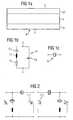
Figuren 23 zeigen zwei Möglichkeiten zur Verschaltung zweier Grundglieder zu einem Filter. -
Figur 4 -
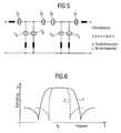
Figur 5 zeigt ein Reaktanzfilter mit vier Grundgliedern. -
Figur 6 zeigt die Dämpfungskurven für ein breitbandiges und ein schmalbandiges Filter. -
Figur 7 zeigt ein Grundglied eines Reaktanzfilters, aufgebaut aus BAW-Resonatoren. -
Figur 8 zeigt eine vereinfachte Filterstruktur mit drei Grundgliedern. -
Figur 9 zeigt das gleiche Filter mit vereinfachter Struktur. -
Figuren 10 und11 zeigen das Durchlassverhalten erfindungsgemäßer Reaktanzfilter. -
Figur 12 zeigt die Impedanzkurven von Resonatoren mit unterschiedlichen Elektrodenmaterialien. -
Figur 13 zeigt einen Resonator mit zusätzlicher dielektrischer Schicht. -
Figur 14 zeigt einen Bridge-Resonator im schematischen Querschnitt. -
Figur 15 zeigt einen BAW-Resonator mit akustischem Spiegel. -
Figuren 16a und 16b zeigen übereinandergelegte Admittanz- und Impedanzkurven für Einzelresonatoren bzw. das Dämpfungsverhalten eines Reaktanzfilters.
-
FIGS. 1a to 1c show a BAW resonator in schematic cross-section, its equivalent circuit diagram and the symbol used for replacement of a resonator. -
Figures 2 and3 show two possibilities for connecting two basic elements to a filter. -
FIG. 4 shows a reactance filter with three basic elements. -
FIG. 5 shows a reactance filter with four bases. -
FIG. 6 shows the attenuation curves for a broadband and a narrowband filter. -
FIG. 7 shows a basic element of a reactance filter constructed of BAW resonators. -
FIG. 8 shows a simplified filter structure with three basic elements. -
FIG. 9 shows the same filter with a simplified structure. -
Figures 10 and11 show the passage behavior of reactance filters according to the invention. -
FIG. 12 shows the impedance curves of resonators with different electrode materials. -
FIG. 13 shows a resonator with additional dielectric layer. -
FIG. 14 shows a bridge resonator in schematic cross section. -
FIG. 15 shows a BAW resonator with acoustic mirror. -
FIGS. 16a and 16b show superimposed admittance and impedance curves for single resonators or the damping behavior of a reactance filter.
Erstes Ausführungsbeispiel:
- Es werden entsprechend
Figur 1 aufgebaute Resonatoren zu einem Reaktanzfilter verschaltet. Jeder Resonator umfaßt eine erste Elektrodenschicht E1, eine piezoelektrische Schicht P und eine zweite Elektrodenschicht E2. Im rechten Teil der Figur ist das üblicherweise für Resonatoren verwendete Symbol aufgezeigt.
- It will be accordingly
FIG. 1 constructed resonators connected to a reactance filter. Each resonator comprises a first electrode layer E1, a piezoelectric layer P and a second electrode layer E2. In the right part of the figure, the symbol commonly used for resonators is shown.
Die Durchlaßkurve 2 in
Zweites Ausführungsbeispiel:
- Es wird wiederum ein Reaktanzfilter mit einem gemäß
Figur 2 verschalteten Grundglied aufgebaut, wobei beide Resonatoren wie inFigur 1k 2 eff 1, wird im Ergebnis ein Reaktanzfilter erhalten,dessen Durchlaßkurve 2 inFigur 11 dargestellt ist. Es zeigt sich, daß dieKurve 2 des erfindungsgemäßen Filters eine linke Flanke aufweist, die deutlich steiler eingestellt ist als die linke Flanke der Kurve 1, die das Durchlaßverhalten eines bekannten Reaktanzfilters zeigt, bei dem für beide Resonatoren das gleiche Elektrodenmaterial (Wolfram) verwendet wurde.
- It is again a reactance with a according to
FIG. 2 interconnected basic element, both resonators as inFIG. 1 are formed. In contrast to the first exemplary embodiment, both resonators have the same piezoelectric material for the layer p, but differ in the electrode material used for the electrodes E1 and E2. While aluminum is used for the resonators R1, tungsten is used as the electrode material for the resonators R2. Sincek 2 eff 2>k 2 eff 1 applies to the effective coupling k 2 eff , the result is a reactance filter whose transmission curve is 2 inFIG. 11 is shown. It can be seen that thecurve 2 of the filter according to the invention has a left flank, which is set much steeper than the left flank of thecurve 1, which shows the transmission behavior of a known reactance filter, in which the same electrode material (tungsten) was used for both resonators ,
Drittes Ausführungsbeispiel:
- Es wird ein Resonator gemäß
Figur 13 ausgebildet. Dieser umfaßt zwischen einer ersten Elektrode E1 und einer zweiten Elektrode E2, beispielsweise aus Aluminium, eine piezoelektrische Schicht P, beispielsweise aus Aluminiumnitrid sowie eine dielektrische Schicht D beispielsweise aus Siliziumoxid. Bei einem Schichtanteil der Siliziumdioxidschicht von 16% sinkt der Kopplungskoeffizient k2 eff von einemWert von 0,0645, bestimmt an einem Resonator gemäßFigur 1Figur 13 ausgebildeten Resonator. Dieser weist daher einen geringeren Abstand von Resonanz- und Antiresonanzfrequenz auf und läßt sich in Kombination mit herkömmlichen Resonatoren (sieheFigur 1 ) kombinieren, wobei im Reaktanzfilter (beispielsweise gemäßFigur 7 ) die seriellen und parallelen Resonatoren unterschiedlich ausgebildet sind, nämlich jeweils gemäßFigur 1 bzw. Figur 17.
- There will be a resonator according to
FIG. 13 educated. This comprises between a first electrode E1 and a second electrode E2, for example made of aluminum, a piezoelectric layer P, for example made of aluminum nitride and a dielectric layer D, for example made of silicon oxide. With a layer fraction of the silicon dioxide layer of 16%, the coupling coefficient k 2 eff decreases from a value of 0.0645, determined on a resonator according to FIGFIG. 1 with aluminum nitride as a piezoelectric layer to a value of 0.057 for the invention as inFIG. 13 trained resonator. This therefore has a smaller distance from the resonance and anti-resonant frequency and can be used in combination with conventional resonators (seeFIG. 1 ), wherein in the reactance filter (for example according toFIG. 7 ) the serial and parallel resonators are designed differently, namely in each case according toFIG. 1 or FIG. 17.
Viertes Ausführungsbeispiel:
-
Figur 14 zeigt einen als Bridge-Resonator ausgebildeten BAW-Resonator. Dieser weist einenFigur 1 entsprechenden Grundkörper auf, ist jedoch zusätzlich über zwei Sockelstrukturen F mit einem Substrat S verbunden. Da der überwiegende Teil der unteren Elektrode E1 des Resonators Luft als Grenzfläche aufweist, verhält sich dieser Bridgeresonator annähernd wie ein Resonator, der völlig frei schwingen kann. An den beiden Grenzflächen E1/Luft bzw. E2/Luft erfolgt dabei Totalreflektion der akustischen Welle.
-
FIG. 14 shows a designed as a bridge resonator BAW resonator. This one has oneFIG. 1 corresponding base body, but is additionally connected via two base structures F with a substrate S. Since the vast majority of the lower electrode E1 of the resonator has air as an interface, this Bridgeresonator behaves almost like a resonator that can swing completely free. Total reflection of the acoustic wave takes place at the two interfaces E1 / air or E2 / air.
Ein erfindungsgemäßes Reaktanzfilter wird nun aus zumindest einem Grundglied (beispielsweise gemäß
Obwohl die Erfindung nur anhand einiger Ausführungsbeispiele dargestellt und erläutert werden konnte, ist sie selbstverständlich nicht auf diese beschränkt. Mögliche Ausgestaltungen der Erfindung betreffen weitere Methoden, die Bandbreite eines einzelnen Resonators zu variieren und dementsprechend Resonatoren mit unterschiedlichen Bandbreiten in erfindungsgemäßen Filtern einzusetzen. Die Variationen können dabei einzelne Resonatoren in einem Zweig, einzelne Resonatoren in beiden Zweigen, alle Resonatoren in einem Zweig oder alle Resonatoren in beiden Zweigen umfassen.Although the invention has been illustrated and explained with reference to some embodiments only, it is of course not limited to these. Possible embodiments of the invention relate to further methods of varying the bandwidth of a single resonator and accordingly to using resonators with different bandwidths in filters according to the invention. The variations may include individual resonators in a branch, individual resonators in both branches, all resonators in a branch or all resonators in both branches.
Claims (14)
- Reactance filter, formed from resonators of the BAW type,- having at least one basic element with a first resonator in a first branch and a second resonator in a second branch, wherein one of the branches is a serial branch and the other branch is a parallel branch,- wherein each resonator has a specific ratio Vc = C1/C0 of dynamic to static capacitance,- characterized in that the ratio Vc for the resonator in the second branch is set to lower than for the resonator in the first branch.
- Reactance filter according to Claim 1,- wherein the resonator in the first branch is composed of a first piezoelectric material, and the resonator in the second branch is composed of a second piezoelectric material, which is not the same as the first, and- wherein the coupling coefficient of the first material is higher than that of the second piezoelectric material.
- Reactance filter according to Claim 1 or 2,
wherein the electrode materials for the resonators in the first and second branches are different, wherein the electrode material for the resonators in the first branch produces higher effective coupling than the electrode material of the resonators in the second branch. - Reactance filter according to one of Claims 1 to 3,
wherein the resonators in the second branch have BAW resonators, wherein a layer of a further material is also provided, in addition to a layer of a piezoelectric material, between two electrodes, which further material has a lower dielectric constant than the piezoelectric material. - Reactance filter according to one of Claims 1 to 4,
wherein the effective coupling coefficient for the resonators in the second branch is reduced in comparison to the coupling coefficient of the resonators in the first branch by using an acoustic mirror under an electrode layer. - Reactance filter according to Claim 5,
wherein the resonators in the first and second branches have acoustic mirrors which have different layer thicknesses of the mirror layers and/or different reflection characteristics in the two branches. - Reactance filter according to Claim 5,
wherein only the resonators in the second branch have an acoustic mirror, and a different method for reflection of acoustic waves is used for the resonators in the first branch. - Reactance filter according to one of Claims 1 to 7,
having a plurality of basic elements which are interleaved with one another, wherein the serial branches of the basic elements are connected in series with one another, while the parallel branches are in contrast connected in parallel. - Reactance filter according to Claim 8,
wherein the ratio Vc = C1/C0 of dynamic to static capacitance in at least one resonator in the serial branch is set to a different value than the corresponding ratio of the resonators in the parallel branches. - Reactance filter according to one of Claims 1 to 9,
having a pass response with a passband with a steep left-hand skirt, wherein the ratio Vc = C1/C0 of dynamic to static capacitance in at least one resonator in the parallel branches is reduced in comparison to the resonators in the serial branch. - Reactance filter according to one of Claims 1 to 9,
having a pass response with a passband with a steep right-hand skirt, wherein the ratio Vc = C1/C0 of dynamic to static capacitance in at least one resonator in the serial branch is reduced in comparison to the resonators in the parallel branches. - Reactance filter according to one of Claims 1 to 11,
wherein the resonators in the parallel branches are connected in series with an inductance, and are each individually connected to an earth connection. - Use of a reactance filter according to one of the preceding claims in a wire-less communication system with a transmitting and receiving part, wherein a reactance filter with a steep right-hand skirt is used for the filter in the transmitting part, and a reactance filter with a steep left-hand skirt is used for the filter in the receiving part.
- Use of a reactance filter according to one of the preceding claims in a duplexer with two passband filters, wherein a reactance filter with a steep right-hand skirt is used for the filter with the lower mid-frequency, and a reactance filter with a steep left-hand skirt is used for the filter with the higher mid-frequency.
Applications Claiming Priority (3)
| Application Number | Priority Date | Filing Date | Title |
|---|---|---|---|
| DE10134987A DE10134987A1 (en) | 2001-07-18 | 2001-07-18 | Reactance filter with improved slope |
| DE10134987 | 2001-07-18 | ||
| PCT/DE2002/001761 WO2003009470A1 (en) | 2001-07-18 | 2002-05-16 | Reactance filter having an improved edge steepness |
Publications (2)
| Publication Number | Publication Date |
|---|---|
| EP1407546A1 EP1407546A1 (en) | 2004-04-14 |
| EP1407546B1 true EP1407546B1 (en) | 2010-07-07 |
Family
ID=7692245
Family Applications (1)
| Application Number | Title | Priority Date | Filing Date |
|---|---|---|---|
| EP02737839A Expired - Lifetime EP1407546B1 (en) | 2001-07-18 | 2002-05-16 | Reactance filter having an improved edge steepness |
Country Status (5)
| Country | Link |
|---|---|
| US (1) | US7126253B2 (en) |
| EP (1) | EP1407546B1 (en) |
| JP (1) | JP4243537B2 (en) |
| DE (2) | DE10134987A1 (en) |
| WO (1) | WO2003009470A1 (en) |
Cited By (1)
| Publication number | Priority date | Publication date | Assignee | Title |
|---|---|---|---|---|
| US9595939B2 (en) | 2009-03-04 | 2017-03-14 | Epcos Ag | Reactance filter having a steep edge |
Families Citing this family (19)
| Publication number | Priority date | Publication date | Assignee | Title |
|---|---|---|---|---|
| WO2006137275A1 (en) * | 2005-06-20 | 2006-12-28 | Murata Manufacturing Co., Ltd. | Piezoelectric thin-film filter |
| US7586389B2 (en) * | 2006-06-19 | 2009-09-08 | Maxim Integrated Products, Inc. | Impedance transformation and filter using bulk acoustic wave technology |
| US7598827B2 (en) | 2006-06-19 | 2009-10-06 | Maxim Integrated Products | Harmonic termination of power amplifiers using BAW filter output matching circuits |
| JP2008172713A (en) * | 2007-01-15 | 2008-07-24 | Hitachi Media Electoronics Co Ltd | Piezoelectric thin film resonator, piezoelectric thin film resonator filter, and its manufacturing method |
| US7646265B2 (en) * | 2007-04-11 | 2010-01-12 | Maxim Integrated Products, Inc. | BAW resonator filter bandwidth and out-of-band frequency rejection |
| JP5237138B2 (en) | 2009-01-27 | 2013-07-17 | 太陽誘電株式会社 | Filters, duplexers, communication modules |
| DE102010048965B4 (en) * | 2010-10-20 | 2015-01-22 | Epcos Ag | Band-stop filter with a series connection of at least two pi-members |
| US8508316B2 (en) * | 2010-10-21 | 2013-08-13 | Epcos Ag | Bulk acoustic wave filter of ladder-type structure |
| JP5877043B2 (en) * | 2011-11-22 | 2016-03-02 | 太陽誘電株式会社 | Duplexer |
| JP6183932B2 (en) * | 2013-03-15 | 2017-08-23 | スナップトラック・インコーポレーテッド | Reactance filter with a resonator operating on acoustic waves |
| JP6374653B2 (en) | 2013-11-18 | 2018-08-15 | 太陽誘電株式会社 | Elastic wave filter and duplexer |
| US10581403B2 (en) | 2016-07-11 | 2020-03-03 | Qorvo Us, Inc. | Device having a titanium-alloyed surface |
| US10727809B2 (en) * | 2016-12-15 | 2020-07-28 | Qorvo Us, Inc. | Bulk acoustic wave resonator with multilayer piezoelectric structure |
| US10917072B2 (en) * | 2019-06-24 | 2021-02-09 | Resonant Inc. | Split ladder acoustic wave filters |
| US10547281B1 (en) * | 2018-07-13 | 2020-01-28 | Qualcomm Incorporated | Source impedance tuning circuit for a receive path |
| US11757430B2 (en) | 2020-01-07 | 2023-09-12 | Qorvo Us, Inc. | Acoustic filter circuit for noise suppression outside resonance frequency |
| US20220045664A1 (en) * | 2020-08-10 | 2022-02-10 | RF360 Europe GmbH | Radio frequency (rf) filter with increased shunt resonator coupling coefficient |
| US11632097B2 (en) | 2020-11-04 | 2023-04-18 | Qorvo Us, Inc. | Coupled resonator filter device |
| US11575363B2 (en) * | 2021-01-19 | 2023-02-07 | Qorvo Us, Inc. | Hybrid bulk acoustic wave filter |
Family Cites Families (4)
| Publication number | Priority date | Publication date | Assignee | Title |
|---|---|---|---|---|
| JPS55127719A (en) * | 1979-03-27 | 1980-10-02 | Tohoku Metal Ind Ltd | Ladder-type ceramic filter |
| JPS55127720A (en) * | 1979-03-27 | 1980-10-02 | Tohoku Metal Ind Ltd | Ladder-type ceramic filter |
| JPS63253711A (en) * | 1987-04-09 | 1988-10-20 | Kyocera Corp | Ladder type piezoelectric filter |
| DE19638451A1 (en) * | 1996-09-19 | 1998-04-02 | Siemens Matsushita Components | Reactance filter with SAW resonators |
-
2001
- 2001-07-18 DE DE10134987A patent/DE10134987A1/en not_active Ceased
-
2002
- 2002-05-16 EP EP02737839A patent/EP1407546B1/en not_active Expired - Lifetime
- 2002-05-16 US US10/483,928 patent/US7126253B2/en not_active Expired - Lifetime
- 2002-05-16 DE DE50214525T patent/DE50214525D1/en not_active Expired - Lifetime
- 2002-05-16 JP JP2003514696A patent/JP4243537B2/en not_active Expired - Fee Related
- 2002-05-16 WO PCT/DE2002/001761 patent/WO2003009470A1/en active Application Filing
Cited By (1)
| Publication number | Priority date | Publication date | Assignee | Title |
|---|---|---|---|---|
| US9595939B2 (en) | 2009-03-04 | 2017-03-14 | Epcos Ag | Reactance filter having a steep edge |
Also Published As
| Publication number | Publication date |
|---|---|
| JP2004535738A (en) | 2004-11-25 |
| US20040263286A1 (en) | 2004-12-30 |
| JP4243537B2 (en) | 2009-03-25 |
| EP1407546A1 (en) | 2004-04-14 |
| DE10134987A1 (en) | 2003-02-06 |
| WO2003009470A1 (en) | 2003-01-30 |
| DE50214525D1 (en) | 2010-08-19 |
| US7126253B2 (en) | 2006-10-24 |
Similar Documents
| Publication | Publication Date | Title |
|---|---|---|
| EP1407546B1 (en) | Reactance filter having an improved edge steepness | |
| DE60314715T2 (en) | Piezoelectric resonating filter and duplexer | |
| DE10319554B4 (en) | Bulk acoustic wave device with coupled resonators | |
| DE69533389T2 (en) | Acoustic surface wave filter | |
| DE102004054895B4 (en) | Thin-film BAW filter and method for producing a thin-film BAW filter | |
| DE10246791B4 (en) | Resonant bulk acoustic wave resonator and resonator circuit | |
| EP1196991B1 (en) | Surface acoustic wave (saw) filter of the reactance filter type exhibiting improved stop band suppression and method for optimizing the stop band suppression | |
| EP3189590B1 (en) | Filter with improved linearity | |
| DE4447740B4 (en) | Acoustic surface wave filter | |
| DE10258422A1 (en) | Bulk acoustic wave device for filter in mobile telecommunications terminal, has resonators arranged on acoustic reflector and electrically connected so that coupling capacitance does not shunt them | |
| EP1125364A1 (en) | Surface acoustic wave arrangement with at least two surface acoustic wave structures | |
| DE19822028A1 (en) | Ladder-filter with edge reflection acoustic surface wave filter resonators | |
| DE102015116224B4 (en) | SAW filter with additional pole | |
| WO2014108254A1 (en) | Broad-band filter in branching technology | |
| DE102009009484B4 (en) | Dual-channel SAW filter | |
| WO2017050750A1 (en) | Saw filter having suppressed shear mode | |
| WO2003105340A1 (en) | Adjustable filter and method for adjusting the frequency | |
| DE19610806A1 (en) | Acoustic surface wave filter with sharp cut off characteristic | |
| DE102010005306B4 (en) | DMS filter with improved signal suppression | |
| DE69632710T2 (en) | ACOUSTIC SURFACE WAVE ARRANGEMENT | |
| DE10057848B4 (en) | Reactance filter with improved power compatibility | |
| DE102014118000A1 (en) | Arrangement with a strain gauge filter and steep right flank | |
| WO2003056699A1 (en) | Symmetrically-operating reactance filter | |
| WO2012084461A1 (en) | Filter component | |
| DE10244723B4 (en) | Surface acoustic wave device and communication device |
Legal Events
| Date | Code | Title | Description |
|---|---|---|---|
| PUAI | Public reference made under article 153(3) epc to a published international application that has entered the european phase |
Free format text: ORIGINAL CODE: 0009012 |
|
| 17P | Request for examination filed |
Effective date: 20031113 |
|
| AK | Designated contracting states |
Kind code of ref document: A1 Designated state(s): AT BE CH CY DE DK ES FI FR GB GR IE IT LI LU MC NL PT SE TR |
|
| GRAP | Despatch of communication of intention to grant a patent |
Free format text: ORIGINAL CODE: EPIDOSNIGR1 |
|
| RBV | Designated contracting states (corrected) |
Designated state(s): DE FR GB |
|
| GRAJ | Information related to disapproval of communication of intention to grant by the applicant or resumption of examination proceedings by the epo deleted |
Free format text: ORIGINAL CODE: EPIDOSDIGR1 |
|
| GRAP | Despatch of communication of intention to grant a patent |
Free format text: ORIGINAL CODE: EPIDOSNIGR1 |
|
| GRAS | Grant fee paid |
Free format text: ORIGINAL CODE: EPIDOSNIGR3 |
|
| GRAJ | Information related to disapproval of communication of intention to grant by the applicant or resumption of examination proceedings by the epo deleted |
Free format text: ORIGINAL CODE: EPIDOSDIGR1 |
|
| GRAL | Information related to payment of fee for publishing/printing deleted |
Free format text: ORIGINAL CODE: EPIDOSDIGR3 |
|
| GRAP | Despatch of communication of intention to grant a patent |
Free format text: ORIGINAL CODE: EPIDOSNIGR1 |
|
| GRAS | Grant fee paid |
Free format text: ORIGINAL CODE: EPIDOSNIGR3 |
|
| GRAA | (expected) grant |
Free format text: ORIGINAL CODE: 0009210 |
|
| AK | Designated contracting states |
Kind code of ref document: B1 Designated state(s): DE FR GB |
|
| REG | Reference to a national code |
Ref country code: GB Ref legal event code: FG4D Free format text: NOT ENGLISH |
|
| REF | Corresponds to: |
Ref document number: 50214525 Country of ref document: DE Date of ref document: 20100819 Kind code of ref document: P |
|
| PLBE | No opposition filed within time limit |
Free format text: ORIGINAL CODE: 0009261 |
|
| STAA | Information on the status of an ep patent application or granted ep patent |
Free format text: STATUS: NO OPPOSITION FILED WITHIN TIME LIMIT |
|
| 26N | No opposition filed |
Effective date: 20110408 |
|
| REG | Reference to a national code |
Ref country code: DE Ref legal event code: R097 Ref document number: 50214525 Country of ref document: DE Effective date: 20110408 |
|
| GBPC | Gb: european patent ceased through non-payment of renewal fee |
Effective date: 20110516 |
|
| REG | Reference to a national code |
Ref country code: FR Ref legal event code: ST Effective date: 20120131 |
|
| PG25 | Lapsed in a contracting state [announced via postgrant information from national office to epo] |
Ref country code: FR Free format text: LAPSE BECAUSE OF NON-PAYMENT OF DUE FEES Effective date: 20110531 |
|
| PG25 | Lapsed in a contracting state [announced via postgrant information from national office to epo] |
Ref country code: GB Free format text: LAPSE BECAUSE OF NON-PAYMENT OF DUE FEES Effective date: 20110516 |
|
| REG | Reference to a national code |
Ref country code: DE Ref legal event code: R082 Ref document number: 50214525 Country of ref document: DE Representative=s name: BARDEHLE PAGENBERG PARTNERSCHAFT MBB PATENTANW, DE Ref country code: DE Ref legal event code: R081 Ref document number: 50214525 Country of ref document: DE Owner name: SNAPTRACK, INC., SAN DIEGO, US Free format text: FORMER OWNER: EPCOS AG, 81669 MUENCHEN, DE |
|
| PGFP | Annual fee paid to national office [announced via postgrant information from national office to epo] |
Ref country code: DE Payment date: 20210413 Year of fee payment: 20 |
|
| REG | Reference to a national code |
Ref country code: DE Ref legal event code: R071 Ref document number: 50214525 Country of ref document: DE |