EP1406471B1 - Connector assembly for apparatus for regulating the temperature of a fluid - Google Patents
Connector assembly for apparatus for regulating the temperature of a fluid Download PDFInfo
- Publication number
- EP1406471B1 EP1406471B1 EP03027427A EP03027427A EP1406471B1 EP 1406471 B1 EP1406471 B1 EP 1406471B1 EP 03027427 A EP03027427 A EP 03027427A EP 03027427 A EP03027427 A EP 03027427A EP 1406471 B1 EP1406471 B1 EP 1406471B1
- Authority
- EP
- European Patent Office
- Prior art keywords
- fluid
- connector
- connector assembly
- temperature regulation
- temperature
- Prior art date
- Legal status (The legal status is an assumption and is not a legal conclusion. Google has not performed a legal analysis and makes no representation as to the accuracy of the status listed.)
- Expired - Lifetime
Links
Images


Classifications
-
- A—HUMAN NECESSITIES
- A61—MEDICAL OR VETERINARY SCIENCE; HYGIENE
- A61M—DEVICES FOR INTRODUCING MEDIA INTO, OR ONTO, THE BODY; DEVICES FOR TRANSDUCING BODY MEDIA OR FOR TAKING MEDIA FROM THE BODY; DEVICES FOR PRODUCING OR ENDING SLEEP OR STUPOR
- A61M5/00—Devices for bringing media into the body in a subcutaneous, intra-vascular or intramuscular way; Accessories therefor, e.g. filling or cleaning devices, arm-rests
- A61M5/44—Devices for bringing media into the body in a subcutaneous, intra-vascular or intramuscular way; Accessories therefor, e.g. filling or cleaning devices, arm-rests having means for cooling or heating the devices or media
-
- G—PHYSICS
- G05—CONTROLLING; REGULATING
- G05D—SYSTEMS FOR CONTROLLING OR REGULATING NON-ELECTRIC VARIABLES
- G05D23/00—Control of temperature
- G05D23/19—Control of temperature characterised by the use of electric means
- G05D23/1927—Control of temperature characterised by the use of electric means using a plurality of sensors
- G05D23/193—Control of temperature characterised by the use of electric means using a plurality of sensors sensing the temperaure in different places in thermal relationship with one or more spaces
- G05D23/1931—Control of temperature characterised by the use of electric means using a plurality of sensors sensing the temperaure in different places in thermal relationship with one or more spaces to control the temperature of one space
-
- G—PHYSICS
- G05—CONTROLLING; REGULATING
- G05D—SYSTEMS FOR CONTROLLING OR REGULATING NON-ELECTRIC VARIABLES
- G05D23/00—Control of temperature
- G05D23/19—Control of temperature characterised by the use of electric means
- G05D23/20—Control of temperature characterised by the use of electric means with sensing elements having variation of electric or magnetic properties with change of temperature
- G05D23/24—Control of temperature characterised by the use of electric means with sensing elements having variation of electric or magnetic properties with change of temperature the sensing element having a resistance varying with temperature, e.g. a thermistor
-
- A—HUMAN NECESSITIES
- A61—MEDICAL OR VETERINARY SCIENCE; HYGIENE
- A61M—DEVICES FOR INTRODUCING MEDIA INTO, OR ONTO, THE BODY; DEVICES FOR TRANSDUCING BODY MEDIA OR FOR TAKING MEDIA FROM THE BODY; DEVICES FOR PRODUCING OR ENDING SLEEP OR STUPOR
- A61M2205/00—General characteristics of the apparatus
- A61M2205/14—Detection of the presence or absence of a tube, a connector or a container in an apparatus
-
- A—HUMAN NECESSITIES
- A61—MEDICAL OR VETERINARY SCIENCE; HYGIENE
- A61M—DEVICES FOR INTRODUCING MEDIA INTO, OR ONTO, THE BODY; DEVICES FOR TRANSDUCING BODY MEDIA OR FOR TAKING MEDIA FROM THE BODY; DEVICES FOR PRODUCING OR ENDING SLEEP OR STUPOR
- A61M2205/00—General characteristics of the apparatus
- A61M2205/36—General characteristics of the apparatus related to heating or cooling
- A61M2205/366—General characteristics of the apparatus related to heating or cooling by liquid heat exchangers
-
- A—HUMAN NECESSITIES
- A61—MEDICAL OR VETERINARY SCIENCE; HYGIENE
- A61M—DEVICES FOR INTRODUCING MEDIA INTO, OR ONTO, THE BODY; DEVICES FOR TRANSDUCING BODY MEDIA OR FOR TAKING MEDIA FROM THE BODY; DEVICES FOR PRODUCING OR ENDING SLEEP OR STUPOR
- A61M2205/00—General characteristics of the apparatus
- A61M2205/50—General characteristics of the apparatus with microprocessors or computers
-
- A—HUMAN NECESSITIES
- A61—MEDICAL OR VETERINARY SCIENCE; HYGIENE
- A61M—DEVICES FOR INTRODUCING MEDIA INTO, OR ONTO, THE BODY; DEVICES FOR TRANSDUCING BODY MEDIA OR FOR TAKING MEDIA FROM THE BODY; DEVICES FOR PRODUCING OR ENDING SLEEP OR STUPOR
- A61M2205/00—General characteristics of the apparatus
- A61M2205/58—Means for facilitating use, e.g. by people with impaired vision
- A61M2205/583—Means for facilitating use, e.g. by people with impaired vision by visual feedback
-
- A—HUMAN NECESSITIES
- A61—MEDICAL OR VETERINARY SCIENCE; HYGIENE
- A61M—DEVICES FOR INTRODUCING MEDIA INTO, OR ONTO, THE BODY; DEVICES FOR TRANSDUCING BODY MEDIA OR FOR TAKING MEDIA FROM THE BODY; DEVICES FOR PRODUCING OR ENDING SLEEP OR STUPOR
- A61M39/00—Tubes, tube connectors, tube couplings, valves, access sites or the like, specially adapted for medical use
- A61M39/10—Tube connectors; Tube couplings
Definitions
- the present invention relates to a connector assembly integrated into a temperature regulating device for interconnecting a fluid conduit to the device so that a fluid of a desired temperature can be provided via the fluid conduit to a patient.
- Devices for warming physiological fluids, such as for example whole blood and packed cells, to a desired temperature before providing the warmed physiological fluids to a patient are well known.
- the HOTLINE® system made by the assignee of the instant invention.
- Such a device uses a heater and hardwired control for heating a fluid such as for example water to a desire temperature, so that the water can in turn warm the infusate to be provided to the patient via a fluid conduit.
- a fluid such as for example water
- the feedback for such system is hardwired, its feedback response is somewhat limited.
- no meaningful interfacing between the device and the user is achieved.
- EP-A-0463837 upon which the precharacterising clause of claim 1 is based, discloses a connector assembly for coupling a heat exchange conduit to a fluid temperature regulation unit, comprising: mounting means mounted at a given location to said fluid temperature regulation unit to provide a communications path for a fluid whose temperature is regulated by said unit to traverse out of and into said unit; and connector means having coupled thereto said heat exchange conduit matable with said mounting means, said connector means having one port means for receiving and routing said fluid from said fluid temperature regulation unit to said heat exchange conduit and another port means for returning said fluid from said heat exchange conduit to said fluid temperature regulation unit, characterised in that said mounting means is mounted coplanarly along one wall of said unit, said one and other port means being configured in said connector means to complete said communications path provided by said mounting means when said connector means is demountably engaged to and sealingly mated with said mounting means by said connector means being moved to a predetermined location coplanarly along said one wall relative to said mounting means.
- a connector assembly for coupling a heat exchange conduit to a fluid temperature regulation unit, comprising: mounting means mounted at a given location to said fluid temperature regulation unit to provide a communications path for a fluid whose temperature is regulated by said unit to traverse out of and into said unit; and connector means having coupled thereto said heat exchange conduit matable with said mounting means, said connector means having one port means for receiving and routing said fluid from said fluid temperature regulation unit to said heat exchange conduit and another port means for returning said fluid from said heat exchange conduit to said fluid temperature regulation unit, characterised in that said mounting means is mounted coplanarly along one wall of said unit, said one and other port means being configured in said connector means to complete said communications path provided by said mounting means when said connector means is demountably engaged to and sealingly mated with said mounting means by said connector means being moved to a predetermined location coplanarly along said one wall relative to said mounting means.
- a connector assembly in accordance with the invention has the advantage that it is designed in such a way that the circulation of fluid through the fluid conduit occurs only if the fluid conduit is correctly mated to the connector assembly.
- the fluid conduit can be replaced by a temperature calibration or checking device, Once the temperature checking device correctly fits to the connector assembly, a test takes place for determining the calibration and integrity of the various temperature sensing components in a temperature regulating section, to therefore ensure that the device is operating properly.
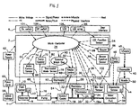
- a temperature regulating device with which the connector assembly of the present invention is used is shown to include three major sections a controller section 2, a temperature regulation section 4 and a user interface section 6. The three sections are communicatively interconnected.
- temperature regulation section 4 has a reservoir 8 for storing the fluid that is to be temperature regulated.
- the fluid could be any type of fluid including non-compressible fluid or gas. But for the discussion of the exemplar embodiment, water is the preferred fluid to be used.
- Reservoir 8 has communicatively connected thereto a float sensor 10 that senses the level of fluid in reservoir 8.
- an ultraviolet light source 12 which could direct an ultraviolet light to the fluid in the reservoir for killing any bacteria and/or microbes that may find their way into the fluid stored in reservoir 8.
- ultraviolet sensor 12 may also be positioned along the tubings that connect to the bidirectional inlet/outlet ports in the temperature regulation section 4 for killing any bacteria and/or microbes that may be in the tubings and/or in the fluid that flows through the tubings.
- Pump 14 is a bidirectional pump or equivalents thereof that may be purchased from a number of companies including the Gorman-Rupp Company.
- pump 14 could be a bidirectional positive displacement gear pump that can circulate the fluid in either a forward direction, as indicated for example by arrow 16, or in a reverse direction so as to route the fluid back into reservoir 8.
- Pump 14 is connected to a heater, or cooler, 18 which, in the instance that it is operating as a heater, warms the fluid circulated thereto by pump 14 to a desired temperature.
- a heater or cooler
- the fluid output from pump 14 may also be cooled by cooler 18 to a desired temperature.
- heater, or cooler, 18 works as a heater for warming a fluid output from pump 14.
- the fluid, in this instance water, output from heater 18 is routed to a tubing 20 that has communicatively connected thereto two thermistors 22 and 24. These thermistors each independently sense the temperature of the fluid being heated by heater 18 and flowing along tubing 20. Respective signals are output by the thermistors to processor 26 via signal or channel lines 28 and 30.
- Thermistors 22 and 24 are each calibrated to a set point, so that theoretically each of the thermistors should measure the same temperature from the fluid flowing along tubing 20. If for any reason the respective temperatures measured by thermistors 22 and 24 diverge for more than a predetermined amount, such as for example 3°C, then processor 26, upon sensing this variance, would shut the system down. This is done in order to ensure that the temperature of the fluid being heated by heater 18 remains accurate.
- Thermistors 22 and 24 each also work cooperatively with processor 26 to ensure that the system does not reach an overheated or overtemp condition. This is done by thermistors 22 and 24 each continuously reporting to processor 26 whether a temperature higher than the normal operating temperature, i.e., an "overtemp" condition such as for example 2°C above the normal temperature, has been sensed. If either one of thermistors 22 and 24 senses such overtemp condition, the heater is shut down.
- each of thermistors 22 and 24 is set to have its circuit electrically respond to the overtemp condition so as to automatically shut down the operation of heater 18. Once the system has been shut down due to an overtemp condition, the machine would remain in such fail-safe shut down mode.
- one of thermistors 22 and 24 is used to activate a control relay to turn heater 18 "on” and “off” in response to the temperature of the fluid to thereby maintain the temperature of the heated fluid to be within an acceptable temperature range.
- Filter 32 may have connected thereto a sensor 34, which may continuously monitor the filtering element of filter 32 for ensuring that the filter element continues to be able to filter out microbes and bacteria. Sensor 32 may do this by detecting the opacity of the filter element in filter 32.
- a signal from sensor 34 is fed to processor 26 by means of a signal line 36.
- the fluid from tubing 20 is routed to a water circulation port 38 that comprises inlet/outlet bidirectional ports that enable the fluid from tubing 20 to be routed to a fluid conduit in the form of a disposable 40.
- Disposable 40 may be a triple lumen conduit such as that described in U.S.-A-5,097,898 and US-A-5,063,994.
- the mating of disposable 40 to bidirectional ports 38 is done by means of a connector assembly such as for example that shown in Figs. 7-15. A more detailed discussion of the connector assembly and the connector mated thereto from which disposable 40 extends will be given, infra.
- Bio-Test sensor 42 is an electromagnetic sensor that senses the mating to the connector assembly of a calibration device such as a Temp Check 46 for initiating a test that determines the integrity of various components in temperature regulating section 4.
- Disposable sensor 44 is an electromechanical switch or sensor that continuously monitors whether the fluid conduit, i.e., disposable 40, or Temp Check 46 is fitted correctly to the connector assembly. If either of disposable 40 or Temp Check 46 is not mated to the connector assembly properly, sensor 42 sends a signal to processor 26, which in turn prevents the instant invention device from working.
- an additional sensor 45 which may be either an electromagnetic sensor or an electromechanical switch positioned relative to the connector assembly, continuously monitors the integrity of the connector assembly. In the event that tampering of the connector assembly, such as for example the removal thereof, is detected, sensor 45 would send a signal to processor 26 to inform processor 26 to disable the device. This could be done by processor 26 sending a signal such as for example a delete signal to an EPROM, wherein various functional algorithms relating to the operation of the device are stored, to erase at least one of the algorithms that operates the device. Thereafter, to reenable the device, the device has to be returned to the factory so that the erased algorithm could be reinstored.
- disposable 40 includes the conduit to which infusate 48 is input so that the infusate can be provided to a needle 50, which is used to infuse the patient.
- Infusate 48 as it flows through disposable 40, is warmed to the desired temperature by the fluid that is being circulated from pump 14 to disposable 40.
- Controller section 2 of the instant invention device has connected to its processor 26 a number of components.
- a signal is provided to processor 26 from float sensor 10 via line 64.
- float sensor 10 senses the level of fluid in reservoir 8, so that if the level happens to fall below a predetermined level, processor 26 can notify the user that additional fluid is required via some indicator such as for example a buzzer 66 and/or a light at LED array 96.
- some indicator such as for example a buzzer 66 and/or a light at LED array 96.
- float sensor 18 were to sense the level of fluid in reservoir to be below a minimum level, it will send a signal to processor 26, which will then shut the system down.
- Processor 26 has also input thereto a signal from a motor current sensor 66 that senses the current of pump 14 by way of a signal line 68 to pump 14. The value of the sensed current informs processor 26 of the operational status of pump 14. To wit, if sensor 66 senses a normal current, for example from 100-500 ⁇ A, then processor 26 knows that pump 14 is operating normally. However, if the current is sensed to be above 500 ⁇ A, for example between 500 and 800 ⁇ A, then processor 26 knows that something is wrong. Accordingly, a "NOT WARMING" warning is displayed to the user. At this stage, the problem could be one that is readily fixable, such as for example disposable 40 having a kink that is easily straightened out.
- processor 26 knows that something is wrong with the motor of pump 14. At this time, in addition to displaying the "NOT WARMING" warning, processor 26 could also shut down pump 14 to prevent any potential damage thereto.
- a predetermined amount for example 800 ⁇ A
- Processor 26 is further connected to a pump control 72 by means of a signal line 74.
- Pump control 72 controls the direction of rotation of pump 14 for circulation of the fluid in either the forward direction, as exemplified by arrow 16, or the reverse direction so as to drain the fluid in disposable 40 and tubing 20 back into reservoir 8.
- processor 26 would instruct pump control 72 to reverse the rotation of pump 14 to thereby drain the fluid in tubing 20 and disposable 40 back into reservoir 8.
- thermostat mode sensor 78 is communicatively connected to processor 26 via a signal line 80.
- Thermostat mode sensor 78 is also connected to an external thermostat 82, which continuously monitors the operating temperature of heater 18 via a signal line 84.
- Thermostat 82 is a "fail-sale" device in that it is preset to a given temperature that, if sensed, causes it to shut down the system so as to prevent any catastrophic damage to the device and potential harm to the patient.
- Thermostat 82 therefore acts as a backup to thermistors 22 and 24 in the event that both of those thermistors fail.
- the shut down temperature in thermostat 82 is preset to a value that is higher than the set point temperature and the overtemp condition thermistors 22 and 24 each were calibrated to respond to, and quite a bit higher than what is considered to be the operating temperature of heater 18.
- thermostat mode sensor 78 could be an inductor coil placed about the conductor that provides power to thermostat 82 so as to sense the current flowing through thermostat 82. If per chance thermostat 82 fails, sensor 78 can sense that there is no current flowing therethrough. It will accordingly inform processor 26 that thermostat 82 has malfunctioned.
- An external watchdog module 90 which is an electrical circuit that comprises a Schmidt trigger and its own time base, is communicatively connected to processor 26. Watchdog 90 continuously monitors the operation of processor 26 per its timing and compares the time base of processor 26 with its own clock pulses to ensure that processor 26 is operating properly. Watchdog 90 would shut the system down if it senses that processor 26 is not functioning properly by cutting off power to heater 18, such as for example by opening a safety relay that connects heater 18 to its power source. Note that in addition to external watchdog 90, there is an internal watchdog in controller 26 that monitors the execution of the software of the system.
- buttons 94 that sense the operation of LED array 96 located in user interface section 6.
- Buzzer 66 may be used to alert the user of problems in the device of the instant invention that he or she should be made aware of.
- buzzer 66 outputs different sound signals for different problems, as for example three beeps or a specific tone for an "OVERTEMP" condition as compared to one beep or another tone for a "NOT WARMING" condition.
- a buzzer function sensor 96 senses the signals output from buzzer 66 and provides a feedback to processor 26 by means of a feedback signal line 98.
- Processor 26 is further communicatively connected to Bio-Test sensor 42 and disposable sensor 44 by means of signal lines 100 and 102, respectively.
- processor 26 When a signal is sent by Bio-Test sensor 42 to processor 26 to inform it that Temp Check 46 is in place, processor 26 begins a calibration and temperature testing procedure for determining the integrity of various components of the system. These components include thermistors 22, 24 and thermostat 82.
- each of thermistors 22 and 24 is calibrated to respond to a given set point, for example 41.9°C, that the temperature of the fluid is to be regulated at. Moreover, thermistors 22 and 24 each are tested to ensure that they each will electrically respond to an "overtemp" condition.
- An overtemp condition may for example be set to occur if the temperature of the fluid is measured to be 1.5°C above the set point.
- Thermostat 82 is tested separably from both thermistors 22 and 24. Bypassing thermistors 22 and 24, thermostat 82 is tested to determine if it will open at a predetermined fail-safe temperature that is well above the temperature at which thermistors 22 and 24 each become electrically open. In other words, by making sure that thermostat 82 will open at the failsafe temperature, the system is ensured to shut down at that predetermined fail-safe temperature to prevent any catastrophic occurrences.
- user interface section 6 has an on switch 104, an off switch 106, a LCD display 108, as well as the previously mentioned LED array 96.
- the on and off switches 104, 106 are switches that, once activated, would signal processor 26 to take different predetermined courses of action, which will be discussed in detail with respect to the flow diagrams of Figs. 2 and 6.
- LCD display 108 is a display that provides to the user messages in any one of a plurality of languages so that the device of the instant invention can be shipped to various countries without having to have its menus and instructions reprogrammed specifically for the country that it is to be shipped to.
- LCD display 108 The interaction between LCD display 108 and controller 28 is conventional in that the typical drivers and signal generators, as well as conventional memory stores such as ROMs that store the different languages and menus, are used.
- LED array 96 provides the user an indication of the types of functions that the device is performing.
- a touch sensitive screen or input keys provide the interfacing between the user and the instant invention device.
- FIG. 2 An overall top level flow diagram illustrating the main operation processes of the system is shown in Fig. 2 As shown, there are five major processes. These are: Mains Connection, Initialization and Power On Testing process 400; Normal Operation Process 402; Main Control process 404; Turn Off process 406 and Bio-test process 408. These processes are to be discussed hereinbelow with reference to Figs. 3-6.
- a combination Mains Connection and Power On Self Test (POST) flow chart is provided.
- the Power On process begins when the mains are connected at step 105.
- the POST process is initiated at step 114 when ON switch 104 is pressed.
- the power on test is a self test to be performed by the system to test its various components such as for example its RAM, ROM and any other component that may deal with the safety or temperature regulating aspect of the device. As its name implies, every time that the machine is turned on, the testing of the various components of the system is performed.
- step105 mains are connected. Thereafter, an initialization test 107 is performed in the read only memory (ROM) of the device in which the various programs or software routines for performing the various functions of the device is tested. A test is also performed on the random access memory (RAM) of the device.
- the internal register of the device is also initialized. Such internal register initialization also includes the initialization of the LCD display and the EEPROM. Note that such ROM, RAM, EEPROM and registers are common in electronic devices and therefore are not shown in the block diagram of the device as illustrated in Fig. 1.
- step 108 the operation language is identified.
- This operation language could be any one of a plurality of languages stored in a memory in the device so that the device can be sold in most of the countries of the world.
- step 110 the timers are initialized. Internal watchdog operation begins to monitor program flow. Note that steps 107-110 do not need to be processed in the particular order shown.
- step 114 the process waits until on button 104 is pushed, per step 114.
- the system proceeds to step 118 to perform the POST test for determining the integrity of the various components of the system.
- This POST process includes testing of all components associated with the safety of the system such as the CPU, RAM, ROM, etc. If the system tests out okay per step 120, the appropriate green LED at LED array 96 is lit, per step 122, to indicate to the user that the system is operational. Thereafter, per step 124, the device proceeds to perform the normal operation, and the POST process is completed.
- step 120 if the system tests abnormal in step 120, a failed self test alarm, as indicated by a yellow LED in LED array 96, is lit to indicate to the user that the self test has failed. If there is a failed self test, the process proceeds to step 128 to output a disabled interrupt to the processor for disabling the system. The process then waits until the off button is pressed by the user per step 116 to turn off the system.
- a predetermined set point temperature is provided by the user and read at step 132.
- the fluid level is tested to determine whether it is at least 250 ml, the minimum fluid level allowing the machine to operate. Any level lower, the machine will shut down. If the fluid level is sensed to be between 250 ml and 300 ml, fluid needs to be added to reservoir 8. Thus, if per step 134, the water level is determined to be less than 250ml, a yellow LED is lit on LED array 96 to indicate to the user that he or she should add fluid, per step 138. At the same time, power is shut off for heater 18 per step 139. The device, in the meantime, will not operate.
- the yellow LED is lit on LED array 96 to indicate to the user that the fluid level in reservoir 8 is low, and the message "Water Tank Low” is flashed periodically on the LCD display.
- step 142 tests whether the disposable fluid conduit has been properly connected to the connector assembly. If it turns out that Temp Check 46 is properly fitted to the connector assembly, the "Bio-Test" of the system, which is shown in much greater detail in Figs. 16 and 17, begins, per step 144.
- step 148 initialize pump 14 to circulate the temperature regulated fluid, and light the green LED on LED array 96 to indicate to the user that the device is operating normally. Thereafter, the timer for external watchdog 90 is enabled, per step 150. After which the operation process exits from its start up phase, per step 154.
- step 142 a determination is made on whether the connector for the fluid conduit has been properly connected to the connector assembly. If it is determined that the fluid conduit connector is not properly connected, a yellow LED relating to disposable fluid conduit 40 is lit on LED array 96 to indicate to the user that disposable 40 is not properly connected, per step 156. Thereafter, the process waits for the activation of the off switch, per step 158. Once the off button is pressed per step 158, the device is turned off, per step 160.
- step 200 the process proceeds to step 202 for determining whether the timer interrupt flag has been raised. If it has, the process proceeds to timer interrupt service per step 204 for clearing the timer interrupt. If there is no timer interrupt, the process proceeds to step 206 to determine whether any buttons have been pushed. If a button has been pushed, the process proceeds to step 208 for the user to do what he or she needs to do to clear the button interrupt. The process then proceeds to step 210 at which time the system determines whether its overall status is okay. If it is, the green LED at LED array 96 is lit, per step 212 to signify that the system is operational.
- step 214 a determination is made on whether pump 14 and heater 18 each have been turned on, per step 214. If yes, the process proceeds back to the beginning of the loop process to wait for an interrupt from either the timer or the off switch, per steps 202 and 204, respectively. If on the other hand, per step 214, it is determined that pump 14 and heater 18 have not been turned on, the process proceeds to step 216 to turn on pump 14 and heater 18. The process then proceeds to the beginning of the loop to wait for either the timer interrupt or the button interrupt, as indicated per steps 202 or 206, respectively.
- step 210 As mentioned previously, provided that the status of the device remains okay at step 210, the device is deemed to be operational and the green LED is lit per step 212. However, if it is determined per step 210 that any one of the tests as shown in Fig. 5 has failed, then a number of additional tests will take place. This is illustrated starting with step 218 in which a determination is made on whether the fluid level is less than the minimum acceptable level. If it is less than the minimal acceptable level, pump 14 and heater 18 are each turned off, per step 220. Also, per step 220, the "add water” yellow LED on LED array 96 is lit to warn the operator that more water or fluid is required. The process thereafter returns to the beginning of the loop to once again wait for interrupts or any sign that the status of the device is acceptable.
- step 218 determines whether reservoir 8 does have the minimum fluid level at step 18. If it is determined that reservoir 8 does have the minimum fluid level at step 18, the process proceeds to step 222 to determine whether the fluid level at reservoir 8 has reached the maximum fluid level. If it has not, a yellow LED is lit at LED array 96 to indicate to the user that the water level is low, per step 224. In this instance, the device remains operational, as the process proceeds to step 214 to determine the operational status of pump 14 and heater 18.
- tests after the status of the device has been deemed not to be okay include: testing the connection of the fluid exchange conduit with the connector assembly per step 226, testing the temperature per step 228, testing the operation of pump 14 per step 230, testing thermostat 82 per step 232, testing thermistors 22 and 24 per step 234, testing the A/D and D/A converters per step 231, testing of data integrity per step 233 and testing for kinks in the conduit per step 235. If each of those tests shows that the status of the device is acceptable, the process proceeds to step 214 for determining whether pump 14 and heater 18 are each turned on. However, if any one of tests 226-235 fails, pump 14 and heater 18 each are turned off, as indicated per each of steps 236-244.
- Test 234 of the thermistors proceeds with the reading of the first thermistor 22.
- the temperature of the second thermistor 24 is then read.
- the respective temperatures of the thermistors are then compared. If both temperatures are the same, the power to heater 18 is turned on. On the other hand, if the respective temperatures of the thermistors are not the same, the system status fail flag for the thermistors is raised to activate a yellow LED to warn the user that a problem exists per step 244. At the same time, a "Fail Self Test" message is displayed to the user.
- A/D and D/A test 2331 Another test that may require some clarification is the A/D and D/A test 231. This test involves the periodic cross checking of the analog to digital converter with the digital to analog converter to insure the integrity of the respective converters for signal conversion.
- Fig. 6 illustrates the process when the off button is pressed.
- step 246 which indicates that the off button is pressed
- the process proceeds to a determination, per step 248, on whether the turning off is a "normal" off. If it is not, every component in the system is turned off per step 250, as the system is programed to assume that something catastrophic may have happened. Conversely, if the system determines that it is a "normal" off, the process proceeds to step 249 to turn off heater 18, and then step 252 to turn off the motor for pump 14. Next, per step 254, the system waits a predetermined time period, for example 1 second, to make sure that the motor for pump 14 has stopped.
- a predetermined time period for example 1 second
- step 256 pump 14 is turned on in reverse, so as to reverse the circulation movement of the fluid in the system including the fluid conduit connected to the connector assembly.
- step 258 whereby the fluid in both tubing 20 and the disposable fluid conduit 40 is pumped back to reservoir 8.
- the reverse circulation process continues for a given time period, such as for example 10 seconds, as indicated per step 266.
- a "Remove Disposable” message may also be displayed to the user.
- a time delay such as for example 15 second may be programmed into the system to ensure that the various components are turned off in an orderly fashion. After that, the device shuts down per step 250.
- connector assembly 270 is mounted to housing 272 of the device
- a back plate 274 which is mounted to the back of wall 272a of housing 272.
- Back plate 274 is secured to a housing plate 276 positioned to the exterior of wall 272a.
- housing plate 276 is secured to each other at opposite sides of opening 280 at wall 272a as housing plate 276 superposes over back plate 274.
- a sealing gasket 278 is also part of the connector assembly, as it sealingly fits within an opening 282 at back plate 274 encircled by a circumferential wall 284 extending away from a flange 292 of back plate 274.
- the connector for the disposable fluid conduit is shown in Figs. 7-9 as component 282, or otherwise referred to in the instant invention as a reflux connector.
- a disposal or fluid conduit 284 is connected to an opening 286 of reflux connector 282.
- Fluid conduit 287 is a plastic tubing that has an inner flexible plastic tube 288 surrounded concentrically by an outer flexible plastic tube 290.
- the infusate to be provided to the patient is input to tube 288 per arrow 293 via another conduit or tubing 285 at another opening of reflux connector 282.
- the infusate, as it is being supplied to the patient, is warmed by the temperature regulated fluid that flows through tube 290.
- back plate 274 of the connector assembly of the instant invention is a one-piece molded plastic member mounted to the inside of wall 272a of housing 272 via flange 292. This is done by aligning a plurality of holes 294, provided along flange 292 of back plate 274, with a corresponding number of internally threaded supports 296 extending from the back of housing plate 276. See Figs.11 a-11 c. By aligning the proper support 296 with the appropriate hole 294, housing plate 276 superposes over back plate 294 at hole 280 of housing 272. A plurality of screws or other fastening means, not shown, tighten housing plate 276 to back plate 274, while at the same time anchor both back plate 274 and housing plate 276 to wall 272a of housing 272 of the device of the instant invention.
- connector 282 as shown in Figs. 7-9 has at its top portion a number of fins 283 which are not germane to the inventiveness of the instant invention and accordingly are not shown in the connector 282 as illustrated in Figs. 12 and 13.
- inlet/outlet ports 298 and 300 are the supply and return (or reflux) conduits that could be considered as part of the water circulation port 38 shown in Fig. 1.
- supply port 298 the temperature regulated fluid, be it water or otherwise, is fed to fluid conduit 287, and specifically the outer tube 290 that surrounds inner tube 288, for warming the infusate that flows through inner tube 288.
- Return port 300 provides a path whereby the fluid being used to temperature regulate the infusate is circulated back to heater/cooler 18 for more heating and/or cooling, so that the fluid that is used for maintaining a desired temperature for the infusate that flows through inner tube 288 is in turn maintained at a preset temperature.
- Back plate 274 is further shown to include a bore 302 through which a proximity sensor 304 is matingly fitted.
- Sensor 304 could be considered the same as Bio-Test sensor 42 for determining whether or not the Temp Check calibration device 46 has been mated to housing plate 276.
- Proximity switch 304 is an electromagnetic switch that is activated when Temp Check connector 46, which is shaped similar to reflux connector 282, is properly mated to housing plate 276. A magnet embedded in the Temp Check connector 46 activates the proximity switch 304 to inform processor 26 that a test sequence for determining the integrity of the various components of the device of the instant invention is about to take place.
- Back plate 274 moreover is shown to have another bore 304 through which a position switch 307, which is the same as disposable sensor 44 shown in Fig. 1, extends.
- Switch 307 is a conventional switch that includes a plunger 309; which, when reflux connector 28 is mated with housing plate 26 and correctly positioned therein, is forced down into the body of switch 206 to thereby signify to processor 26 that connector 282 is correctly positioned.
- housing plate 276 is shown with greater particularity. As illustrated, housing plate 276 has a main ring-shaped body 306 that has extending therefrom two oppositely located raised portions 308 and 310. Portion 308 has an extending lip 312 and a lead in guide slot or groove 314. Portion 310 likewise has an extending lip 316 with a lead in guide slot or groove 318. In the inner circumference of body 306, there is at least one indent 320 for accepting an extension 322 at a corresponding wing 324 of reflux connector 282. See Figs. 12 and 13. A stop 313 is provided at the end of each of grooves 314 and 318 to prevent further rotation of the base of reflux connector 282 with respect to housing plate 276.
- Reflux connector 282 as best shown in Figs. 12, 13 and 14, has a base 326 that is substantially ring-shaped so as to be matable with housing plate 276.
- An upright portion 328 extends from base 326.
- Extending coplanarly from base 326 are wings 322a and 322b which are mated with portions 308 and 310 of housing plate 276, respectively.
- reflux connector 282 is positioned or superposed over plate 276 with base 326 of connector 282 being in contact with body 306 of housing plate 276, by holding and then turning or rotating raised portion 328 of connector 282 coplanarly with respect to housing plate 276, wing 324a is led by means of guide groove 318 into raised portions 310 while wing 324b is led into raised portion 308 by means of guide groove 314.
- wings 322a and 322b coming into contact and snugly fitting into their corresponding detents 320, a feedback is provided to the user via his or her fingers that indeed connector 282 is positioned correctly to housing plate 276.
- a spear shaped arm 344 extending from base 326 provides a visual indication to the user that connector 282 is positioned properly with respect to housing plate 276.
- Temp Check calibration device 46 is shaped the same as connector 282 with the exception that a magnet is embedded therein for activating proximity switch 304, when it is mated to housing plate 276.
- connector 282 has a first opening 330 to which a fluid conduit such as for example 285 is fitted. Another fluid conduit such as for example 287 is fitted to an opening 332, which is located at the opposite side of upright portion 328. It is at opening 332 that the temperature regulated fluid flows for warming or cooling the infusate flowing through inner tube 288, which is connected to port 334.
- Fig. 14 illustrates in greater detail the respective flows of the infusate and the temperature regulating fluid to/from the fluid conduit via reflux connector 282.
- the bottom of base 326 has a center tubular port 336, which is aligned to and mated with supply port 298 when reflux connector 282 is properly mated to housing plate 276.
- the space defined between base 326 and central port 336 is an open space 338 that becomes fluidly connected to return port 300 when reflux connector 282 is properly positioned with respect to housing plate 276. Accordingly, with respect to reflux connector 282, the infusate is fed to the patient via opening 330 and then tube 288 as shown in Fig. 9.
- the supply fluid as indicated by supply line 340 is input from supply port 298 of back plate 274 to central port 336 of reflux connector 282 and then fed to outer tube 290 for warming or cooling the infusate. And the fluid is returned to heater/cooler 18 via return path 342 through space 338 to return port 30 of back plate 274.
- Temp Check calibration connector 46 When Temp Check calibration connector 46 is mated to housing plate 276 and is sensed by Bio-Test sensor 42, i.e., proximity sensor 304, a signal is provided to processor 26 to inform the system that self testing is to take place.
- the self test or bio-test, begins with step 346.
- the system waits for the activation of either on switch 104 per step 348, or off switch 106 per step 350. Once either on switch 104 or off switch 106 is pressed, the process proceeds to determine the level of testing to be done. A number of tests are then performed as shown in the flow chart of Fig. 16.
- Fig. 17 is an illustration of the operation to be performed by the system to test the integrity of the various components. Again, it is based on Temp Check 46 being correctly mated to the connector assembly and thereafter the activation of the system by means of pressing on switch 104. The various states, from 0-9, relating to the self-testing operation are illustrated in the flow chart of Fig. 17.
- Temp Check connector 46 is structurally very similar to reflux connector 282 with the major differences being that no fluid conduits are connected thereto so that the fluid is refluxed directly in the Temp Check connector itself, and the embedding therein of a magnet for activating the bio-test sensor 42 when it is properly seated onto housing plate 276.
Landscapes
- Engineering & Computer Science (AREA)
- Health & Medical Sciences (AREA)
- Automation & Control Theory (AREA)
- General Physics & Mathematics (AREA)
- Physics & Mathematics (AREA)
- Heart & Thoracic Surgery (AREA)
- Remote Sensing (AREA)
- Life Sciences & Earth Sciences (AREA)
- Animal Behavior & Ethology (AREA)
- General Health & Medical Sciences (AREA)
- Public Health (AREA)
- Veterinary Medicine (AREA)
- Hematology (AREA)
- Biomedical Technology (AREA)
- Anesthesiology (AREA)
- Vascular Medicine (AREA)
- External Artificial Organs (AREA)
- Control Of Temperature (AREA)
- Temperature-Responsive Valves (AREA)
- Infusion, Injection, And Reservoir Apparatuses (AREA)
Abstract
Description
- The present invention relates to a connector assembly integrated into a temperature regulating device for interconnecting a fluid conduit to the device so that a fluid of a desired temperature can be provided via the fluid conduit to a patient.
- Devices for warming physiological fluids, such as for example whole blood and packed cells, to a desired temperature before providing the warmed physiological fluids to a patient are well known. Once such prior art device is the HOTLINE® system made by the assignee of the instant invention. Such a device uses a heater and hardwired control for heating a fluid such as for example water to a desire temperature, so that the water can in turn warm the infusate to be provided to the patient via a fluid conduit. Inasmuch as the feedback for such system is hardwired, its feedback response is somewhat limited. Moreover, given the limitation of the display mechanism in the prior art HOTLINE® device, no meaningful interfacing between the device and the user is achieved.
- EP-A-0463837, upon which the precharacterising clause of
claim 1 is based, discloses a connector assembly for coupling a heat exchange conduit to a fluid temperature regulation unit, comprising: mounting means mounted at a given location to said fluid temperature regulation unit to provide a communications path for a fluid whose temperature is regulated by said unit to traverse out of and into said unit; and connector means having coupled thereto said heat exchange conduit matable with said mounting means, said connector means having one port means for receiving and routing said fluid from said fluid temperature regulation unit to said heat exchange conduit and another port means for returning said fluid from said heat exchange conduit to said fluid temperature regulation unit, characterised in that said mounting means is mounted coplanarly along one wall of said unit, said one and other port means being configured in said connector means to complete said communications path provided by said mounting means when said connector means is demountably engaged to and sealingly mated with said mounting means by said connector means being moved to a predetermined location coplanarly along said one wall relative to said mounting means. - According to the present invention there is provided a connector assembly for coupling a heat exchange conduit to a fluid temperature regulation unit, comprising: mounting means mounted at a given location to said fluid temperature regulation unit to provide a communications path for a fluid whose temperature is regulated by said unit to traverse out of and into said unit; and connector means having coupled thereto said heat exchange conduit matable with said mounting means, said connector means having one port means for receiving and routing said fluid from said fluid temperature regulation unit to said heat exchange conduit and another port means for returning said fluid from said heat exchange conduit to said fluid temperature regulation unit, characterised in that said mounting means is mounted coplanarly along one wall of said unit, said one and other port means being configured in said connector means to complete said communications path provided by said mounting means when said connector means is demountably engaged to and sealingly mated with said mounting means by said connector means being moved to a predetermined location coplanarly along said one wall relative to said mounting means.
- A connector assembly in accordance with the invention has the advantage that it is designed in such a way that the circulation of fluid through the fluid conduit occurs only if the fluid conduit is correctly mated to the connector assembly. To test the integrity of the temperature regulating section, the fluid conduit can be replaced by a temperature calibration or checking device, Once the temperature checking device correctly fits to the connector assembly, a test takes place for determining the calibration and integrity of the various temperature sensing components in a temperature regulating section, to therefore ensure that the device is operating properly.
- In order that the invention may be well understood, there will now be described an embodiment thereof, given by way of example, reference being made to the accompanying drawings, in which:
- Fig. 1 is a block diagram illustrating the various components of a device of which the connector assembly of the present invention forms a part;
- Fig. 2 is a flow diagram providing an overall view of the various functions of the device of Figure 1 ;
- Fig. 3 is a flow diagram illustrating the Power On and Self Test procedures of the device of Figure 1 ;
- Fig. 4 is a flow chart illustrating the Normal Operation and Initialization processes of the device of Figure 1;
- Fig. 5 is a flow chart that illustrates the Main Control Loop process of the device of Figure 1
- Fig. 6 is a flow chart illustrating the Turning Off process of the device;
- Fig. 7 is a perspective view of a connector assembly embodying the instant invention, as it is incorporated into the housing of the device of Figure 1 ;
- Fig. 8 is a perspective exposed view of the various components of the connector assembly of the instant invention;
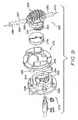
- Fig. 9 is an enlarged view of the components that make up the connector assembly of the instant invention;
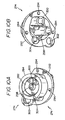
- Fig. 10a is a perspective view of the support plate of the connector assembly of the instant invention which is mounted to the back of an opening of the housing to which bi-directional receptacle ports are located;
- Fig. 10b is a perspective bottom view of the support plate of the connector assembly of Fig. 10a;
- Fig. 11 a to 11 c are respective perspective views of the housing plate of the connector assembly of the instant invention;
- Fig. 12 is a perspective semi-exposed view of the connector body of the connector assembly of the instant invention to which is connected a fluid conduit through which the infusate to be provided to the patient flows;
- Fig. 13 is another perspective view of the connector body of the Fig. 12;
- Fig.14 is a perspective bottom view of the connector body of Fig. 12 showing the routes through which the fluid is circulated in the connector body;
- Fig. 15a is a plan view of the housing of the device with the connector assembly being integrated thereto;
- Fig. 15b is an enlarged view of the connector assembly and the mating thereto of the connector of Fig. 12;
- Fig. 16 is a flow diagram illustrating the self-testing procedure of the device and
- Fig. 17 is a flow chart illustrating the operation of the Bio-Test that takes place when a calibration connector device is mated to the connector assembly of the instant invention.
- With reference to Fig. 1, a temperature regulating device with which the connector assembly of the present invention is used is shown to include three major sections a
controller section 2, atemperature regulation section 4 and auser interface section 6. The three sections are communicatively interconnected. - As shown,
temperature regulation section 4 has areservoir 8 for storing the fluid that is to be temperature regulated. The fluid could be any type of fluid including non-compressible fluid or gas. But for the discussion of the exemplar embodiment, water is the preferred fluid to be used.Reservoir 8 has communicatively connected thereto afloat sensor 10 that senses the level of fluid inreservoir 8. There may also be positioned relative toreservoir 8 anultraviolet light source 12 which could direct an ultraviolet light to the fluid in the reservoir for killing any bacteria and/or microbes that may find their way into the fluid stored inreservoir 8. Note thatultraviolet sensor 12 may also be positioned along the tubings that connect to the bidirectional inlet/outlet ports in thetemperature regulation section 4 for killing any bacteria and/or microbes that may be in the tubings and/or in the fluid that flows through the tubings. - Reservoir 8 is connected to a
pump 14, which is a bidirectional pump or equivalents thereof that may be purchased from a number of companies including the Gorman-Rupp Company. In essence,pump 14 could be a bidirectional positive displacement gear pump that can circulate the fluid in either a forward direction, as indicated for example byarrow 16, or in a reverse direction so as to route the fluid back intoreservoir 8. -
Pump 14 is connected to a heater, or cooler, 18 which, in the instance that it is operating as a heater, warms the fluid circulated thereto bypump 14 to a desired temperature. Alternatively, the fluid output frompump 14 may also be cooled bycooler 18 to a desired temperature. For ease of understanding, assume for the rest of this discussion, heater, or cooler, 18 works as a heater for warming a fluid output frompump 14. - The fluid, in this instance water, output from
heater 18 is routed to atubing 20 that has communicatively connected thereto twothermistors heater 18 and flowing alongtubing 20. Respective signals are output by the thermistors toprocessor 26 via signal orchannel lines Thermistors tubing 20. If for any reason the respective temperatures measured bythermistors processor 26, upon sensing this variance, would shut the system down. This is done in order to ensure that the temperature of the fluid being heated byheater 18 remains accurate. -
Thermistors processor 26 to ensure that the system does not reach an overheated or overtemp condition. This is done bythermistors processor 26 whether a temperature higher than the normal operating temperature, i.e., an "overtemp" condition such as for example 2°C above the normal temperature, has been sensed. If either one ofthermistors - Alternatively, each of
thermistors heater 18. Once the system has been shut down due to an overtemp condition, the machine would remain in such fail-safe shut down mode. - To maintain the desired temperature of the fluid, one of
thermistors heater 18 "on" and "off" in response to the temperature of the fluid to thereby maintain the temperature of the heated fluid to be within an acceptable temperature range. - Further along
tubing 20 there may be positioned afilter 32 that could filter out any bacteria and/or microbes that might be in the fluid.Filter 32 may have connected thereto a sensor 34, which may continuously monitor the filtering element offilter 32 for ensuring that the filter element continues to be able to filter out microbes and bacteria.Sensor 32 may do this by detecting the opacity of the filter element infilter 32. A signal from sensor 34 is fed toprocessor 26 by means of a signal line 36. - The fluid from
tubing 20 is routed to awater circulation port 38 that comprises inlet/outlet bidirectional ports that enable the fluid fromtubing 20 to be routed to a fluid conduit in the form of a disposable 40. Disposable 40 may be a triple lumen conduit such as that described in U.S.-A-5,097,898 and US-A-5,063,994. Although not shown in Fig. 1, the mating of disposable 40 tobidirectional ports 38 is done by means of a connector assembly such as for example that shown in Figs. 7-15. A more detailed discussion of the connector assembly and the connector mated thereto from which disposable 40 extends will be given, infra. - Return to Fig. 1. Note that there are a
Bio-Test sensor 42 and adisposable sensor 44 each positioned relative to the bidirectional ports and the connector assembly as mentioned above.Sensor Bio-Test sensor 42 is an electromagnetic sensor that senses the mating to the connector assembly of a calibration device such as aTemp Check 46 for initiating a test that determines the integrity of various components intemperature regulating section 4.Disposable sensor 44, on the other hand, is an electromechanical switch or sensor that continuously monitors whether the fluid conduit, i.e., disposable 40, orTemp Check 46 is fitted correctly to the connector assembly. If either of disposable 40 orTemp Check 46 is not mated to the connector assembly properly,sensor 42 sends a signal toprocessor 26, which in turn prevents the instant invention device from working. - Moreover, an
additional sensor 45, which may be either an electromagnetic sensor or an electromechanical switch positioned relative to the connector assembly, continuously monitors the integrity of the connector assembly. In the event that tampering of the connector assembly, such as for example the removal thereof, is detected,sensor 45 would send a signal toprocessor 26 to informprocessor 26 to disable the device. This could be done byprocessor 26 sending a signal such as for example a delete signal to an EPROM, wherein various functional algorithms relating to the operation of the device are stored, to erase at least one of the algorithms that operates the device. Thereafter, to reenable the device, the device has to be returned to the factory so that the erased algorithm could be reinstored. - With respect to disposable 40, note that it includes the conduit to which
infusate 48 is input so that the infusate can be provided to aneedle 50, which is used to infuse the patient.Infusate 48, as it flows through disposable 40, is warmed to the desired temperature by the fluid that is being circulated frompump 14 to disposable 40. -
Controller section 2 of the instant invention device has connected to its processor 26 a number of components. For example, a signal is provided toprocessor 26 fromfloat sensor 10 vialine 64. As mentioned previously,float sensor 10 senses the level of fluid inreservoir 8, so that if the level happens to fall below a predetermined level,processor 26 can notify the user that additional fluid is required via some indicator such as for example abuzzer 66 and/or a light atLED array 96. Moreover, iffloat sensor 18 were to sense the level of fluid in reservoir to be below a minimum level, it will send a signal toprocessor 26, which will then shut the system down. -
Processor 26 has also input thereto a signal from a motorcurrent sensor 66 that senses the current ofpump 14 by way of asignal line 68 to pump 14. The value of the sensed current informsprocessor 26 of the operational status ofpump 14. To wit, ifsensor 66 senses a normal current, for example from 100-500 µA, thenprocessor 26 knows thatpump 14 is operating normally. However, if the current is sensed to be above 500 µA, for example between 500 and 800 µA, thenprocessor 26 knows that something is wrong. Accordingly, a "NOT WARMING" warning is displayed to the user. At this stage, the problem could be one that is readily fixable, such as for example disposable 40 having a kink that is easily straightened out. Finally, if the sensed current frompump 14 has a value greater than a predetermined amount, for example 800 µA, thenprocessor 26 knows that something is wrong with the motor ofpump 14. At this time, in addition to displaying the "NOT WARMING" warning,processor 26 could also shut downpump 14 to prevent any potential damage thereto. -
Processor 26 is further connected to apump control 72 by means of a signal line 74.Pump control 72 controls the direction of rotation ofpump 14 for circulation of the fluid in either the forward direction, as exemplified byarrow 16, or the reverse direction so as to drain the fluid in disposable 40 andtubing 20 back intoreservoir 8. In receipt of a turn off signal,processor 26 would instructpump control 72 to reverse the rotation ofpump 14 to thereby drain the fluid intubing 20 and disposable 40 back intoreservoir 8. - A
thermostat mode sensor 78 is communicatively connected toprocessor 26 via asignal line 80.Thermostat mode sensor 78 is also connected to anexternal thermostat 82, which continuously monitors the operating temperature ofheater 18 via asignal line 84.Thermostat 82 is a "fail-sale" device in that it is preset to a given temperature that, if sensed, causes it to shut down the system so as to prevent any catastrophic damage to the device and potential harm to the patient.Thermostat 82 therefore acts as a backup tothermistors thermostat 82 is preset to a value that is higher than the set point temperature and theovertemp condition thermistors heater 18. - In the meantime, whether
thermostat 82 is operating properly is periodically being monitored bythermostat mode sensor 78.Sensor 78 could be an inductor coil placed about the conductor that provides power tothermostat 82 so as to sense the current flowing throughthermostat 82. If perchance thermostat 82 fails,sensor 78 can sense that there is no current flowing therethrough. It will accordingly informprocessor 26 thatthermostat 82 has malfunctioned. - An
external watchdog module 90, which is an electrical circuit that comprises a Schmidt trigger and its own time base, is communicatively connected toprocessor 26.Watchdog 90 continuously monitors the operation ofprocessor 26 per its timing and compares the time base ofprocessor 26 with its own clock pulses to ensure thatprocessor 26 is operating properly.Watchdog 90 would shut the system down if it senses thatprocessor 26 is not functioning properly by cutting off power toheater 18, such as for example by opening a safety relay that connectsheater 18 to its power source. Note that in addition toexternal watchdog 90, there is an internal watchdog incontroller 26 that monitors the execution of the software of the system. - Other components connected to
processor 26 that reside onsection 2 include anLED function sensor 94 that senses the operation ofLED array 96 located inuser interface section 6.Buzzer 66, as mentioned previously, may be used to alert the user of problems in the device of the instant invention that he or she should be made aware of. In particular,buzzer 66 outputs different sound signals for different problems, as for example three beeps or a specific tone for an "OVERTEMP" condition as compared to one beep or another tone for a "NOT WARMING" condition. Abuzzer function sensor 96 senses the signals output frombuzzer 66 and provides a feedback toprocessor 26 by means of afeedback signal line 98. -
Processor 26 is further communicatively connected toBio-Test sensor 42 anddisposable sensor 44 by means ofsignal lines Bio-Test sensor 42 toprocessor 26 to inform it thatTemp Check 46 is in place,processor 26 begins a calibration and temperature testing procedure for determining the integrity of various components of the system. These components includethermistors thermostat 82. - In particular, each of
thermistors thermistors thermistors heater 18 is shut down. -
Thermostat 82 is tested separably from boththermistors thermistors thermostat 82 is tested to determine if it will open at a predetermined fail-safe temperature that is well above the temperature at which thermistors 22 and 24 each become electrically open. In other words, by making sure thatthermostat 82 will open at the failsafe temperature, the system is ensured to shut down at that predetermined fail-safe temperature to prevent any catastrophic occurrences. - The last major section in the device is
user interface section 6. As shown,user interface section 6 has an onswitch 104, anoff switch 106, aLCD display 108, as well as the previously mentionedLED array 96. The on and offswitches processor 26 to take different predetermined courses of action, which will be discussed in detail with respect to the flow diagrams of Figs. 2 and 6.LCD display 108 is a display that provides to the user messages in any one of a plurality of languages so that the device of the instant invention can be shipped to various countries without having to have its menus and instructions reprogrammed specifically for the country that it is to be shipped to. The interaction betweenLCD display 108 andcontroller 28 is conventional in that the typical drivers and signal generators, as well as conventional memory stores such as ROMs that store the different languages and menus, are used.LED array 96, as was discussed previously, provides the user an indication of the types of functions that the device is performing. A touch sensitive screen or input keys provide the interfacing between the user and the instant invention device. - An overall top level flow diagram illustrating the main operation processes of the system is shown in Fig. 2 As shown, there are five major processes. These are: Mains Connection, Initialization and Power
On Testing process 400;Normal Operation Process 402;Main Control process 404;Turn Off process 406 andBio-test process 408. These processes are to be discussed hereinbelow with reference to Figs. 3-6. - With reference to Fig. 3, a combination Mains Connection and Power On Self Test (POST) flow chart is provided. The Power On process begins when the mains are connected at
step 105. The POST process is initiated atstep 114 when ONswitch 104 is pressed. Briefly, the power on test is a self test to be performed by the system to test its various components such as for example its RAM, ROM and any other component that may deal with the safety or temperature regulating aspect of the device. As its name implies, every time that the machine is turned on, the testing of the various components of the system is performed. - In particular, starting at step105, mains are connected. Thereafter, an
initialization test 107 is performed in the read only memory (ROM) of the device in which the various programs or software routines for performing the various functions of the device is tested. A test is also performed on the random access memory (RAM) of the device. The internal register of the device is also initialized. Such internal register initialization also includes the initialization of the LCD display and the EEPROM. Note that such ROM, RAM, EEPROM and registers are common in electronic devices and therefore are not shown in the block diagram of the device as illustrated in Fig. 1. - Following the initialization in
step 107, the process proceeds to step 108 in which the operation language is identified. This operation language could be any one of a plurality of languages stored in a memory in the device so that the device can be sold in most of the countries of the world. - In
step 110, the timers are initialized. Internal watchdog operation begins to monitor program flow. Note that steps 107-110 do not need to be processed in the particular order shown. - Next, the process waits until on
button 104 is pushed, perstep 114. When the on button is pushed, the system proceeds to step 118 to perform the POST test for determining the integrity of the various components of the system. This POST process includes testing of all components associated with the safety of the system such as the CPU, RAM, ROM, etc. If the system tests out okay perstep 120, the appropriate green LED atLED array 96 is lit, perstep 122, to indicate to the user that the system is operational. Thereafter, perstep 124, the device proceeds to perform the normal operation, and the POST process is completed. - However, if the system tests abnormal in
step 120, a failed self test alarm, as indicated by a yellow LED inLED array 96, is lit to indicate to the user that the self test has failed. If there is a failed self test, the process proceeds to step 128 to output a disabled interrupt to the processor for disabling the system. The process then waits until the off button is pressed by the user perstep 116 to turn off the system. - The Normal Start Up Operation process is illustrated in Fig. 4, A predetermined set point temperature is provided by the user and read at
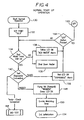
step 132. Atstep 134, the fluid level is tested to determine whether it is at least 250 ml, the minimum fluid level allowing the machine to operate. Any level lower, the machine will shut down. If the fluid level is sensed to be between 250 ml and 300 ml, fluid needs to be added toreservoir 8. Thus, if perstep 134, the water level is determined to be less than 250ml, a yellow LED is lit onLED array 96 to indicate to the user that he or she should add fluid, perstep 138. At the same time, power is shut off forheater 18 perstep 139. The device, in the meantime, will not operate. On the other hand, if the level of fluid is above 250 ml but below 300 ml, the yellow LED is lit onLED array 96 to indicate to the user that the fluid level inreservoir 8 is low, and the message "Water Tank Low" is flashed periodically on the LCD display. - The next step of the normal start up operation process is
step 142, which tests whether the disposable fluid conduit has been properly connected to the connector assembly. If it turns out thatTemp Check 46 is properly fitted to the connector assembly, the "Bio-Test" of the system, which is shown in much greater detail in Figs. 16 and 17, begins, perstep 144. - On the other hand, if a fluid conduit is determined to have been properly connected to the connector assembly per
step 142, the process proceeds to step 148 to initializepump 14 to circulate the temperature regulated fluid, and light the green LED onLED array 96 to indicate to the user that the device is operating normally. Thereafter, the timer forexternal watchdog 90 is enabled, perstep 150. After which the operation process exits from its start up phase, perstep 154. - Return to step 142 where a determination is made on whether the connector for the fluid conduit has been properly connected to the connector assembly. If it is determined that the fluid conduit connector is not properly connected, a yellow LED relating to disposable
fluid conduit 40 is lit onLED array 96 to indicate to the user that disposable 40 is not properly connected, perstep 156. Thereafter, the process waits for the activation of the off switch, perstep 158. Once the off button is pressed perstep 158, the device is turned off, perstep 160. - After the normal start up process as illustrated in the flow chart of Fig. 4, the operation of the device proceeds to the Main Control Loop process as illustrated in the flow chart of Fig. 5. From the
start step 200, the process proceeds to step 202 for determining whether the timer interrupt flag has been raised. If it has, the process proceeds to timer interrupt service perstep 204 for clearing the timer interrupt. If there is no timer interrupt, the process proceeds to step 206 to determine whether any buttons have been pushed. If a button has been pushed, the process proceeds to step 208 for the user to do what he or she needs to do to clear the button interrupt. The process then proceeds to step 210 at which time the system determines whether its overall status is okay. If it is, the green LED atLED array 96 is lit, perstep 212 to signify that the system is operational. - Thereafter, a determination is made on whether
pump 14 andheater 18 each have been turned on, perstep 214. If yes, the process proceeds back to the beginning of the loop process to wait for an interrupt from either the timer or the off switch, persteps step 214, it is determined thatpump 14 andheater 18 have not been turned on, the process proceeds to step 216 to turn onpump 14 andheater 18. The process then proceeds to the beginning of the loop to wait for either the timer interrupt or the button interrupt, as indicated persteps - As mentioned previously, provided that the status of the device remains okay at
step 210, the device is deemed to be operational and the green LED is lit perstep 212. However, if it is determined perstep 210 that any one of the tests as shown in Fig. 5 has failed, then a number of additional tests will take place. This is illustrated starting withstep 218 in which a determination is made on whether the fluid level is less than the minimum acceptable level. If it is less than the minimal acceptable level, pump 14 andheater 18 are each turned off, perstep 220. Also, perstep 220, the "add water" yellow LED onLED array 96 is lit to warn the operator that more water or fluid is required. The process thereafter returns to the beginning of the loop to once again wait for interrupts or any sign that the status of the device is acceptable. - Other tests are continuously being performed on the device. For example, after the minimum fluid level test at
step 218 is performed, if it is determined thatreservoir 8 does have the minimum fluid level atstep 18, the process proceeds to step 222 to determine whether the fluid level atreservoir 8 has reached the maximum fluid level. If it has not, a yellow LED is lit atLED array 96 to indicate to the user that the water level is low, perstep 224. In this instance, the device remains operational, as the process proceeds to step 214 to determine the operational status ofpump 14 andheater 18. - Other tests after the status of the device has been deemed not to be okay include: testing the connection of the fluid exchange conduit with the connector assembly per
step 226, testing the temperature perstep 228, testing the operation ofpump 14 perstep 230, testingthermostat 82 perstep 232,testing thermistors step 234, testing the A/D and D/A converters perstep 231, testing of data integrity perstep 233 and testing for kinks in the conduit perstep 235. If each of those tests shows that the status of the device is acceptable, the process proceeds to step 214 for determining whetherpump 14 andheater 18 are each turned on. However, if any one of tests 226-235 fails, pump 14 andheater 18 each are turned off, as indicated per each of steps 236-244. Also, the appropriate LED atLED array 96 is lit for whichever test has failed at each of steps 236-244. The process of Fig. 5 continues until either the time for the device to remain operational has run out or until the off button is pushed, persteps - With respect to
tests 218 to 235, note in particular the following.Test 234 of the thermistors proceeds with the reading of thefirst thermistor 22. The temperature of thesecond thermistor 24 is then read. The respective temperatures of the thermistors are then compared. If both temperatures are the same, the power toheater 18 is turned on. On the other hand, if the respective temperatures of the thermistors are not the same, the system status fail flag for the thermistors is raised to activate a yellow LED to warn the user that a problem exists perstep 244. At the same time, a "Fail Self Test" message is displayed to the user. - Another test that may require some clarification is the A/D and D/A
test 231. This test involves the periodic cross checking of the analog to digital converter with the digital to analog converter to insure the integrity of the respective converters for signal conversion. - Yet another test that is worth discussing is the
data integrity test 233. There all critical data including the exemplar set point 41.9°C is read by using two independent routines. A comparison test is then performed on the data. If the comparison test fails, then the yellow LED is turned on, the message "Failed Self-Test" displayed and the appropriate alarm sequence is generated bybuzzer 66. Moreover, pump 14 andheater 18 are each turned off. - Fig. 6 illustrates the process when the off button is pressed. Starting with
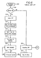
step 246 which indicates that the off button is pressed, the process proceeds to a determination, perstep 248, on whether the turning off is a "normal" off. If it is not, every component in the system is turned off perstep 250, as the system is programed to assume that something catastrophic may have happened. Conversely, if the system determines that it is a "normal" off, the process proceeds to step 249 to turn offheater 18, and then step 252 to turn off the motor forpump 14. Next, perstep 254, the system waits a predetermined time period, for example 1 second, to make sure that the motor forpump 14 has stopped. - Thereafter, per
step 256, pump 14 is turned on in reverse, so as to reverse the circulation movement of the fluid in the system including the fluid conduit connected to the connector assembly. This is signified perstep 258 whereby the fluid in bothtubing 20 and the disposablefluid conduit 40 is pumped back toreservoir 8. The reverse circulation process continues for a given time period, such as for example 10 seconds, as indicated perstep 266. At which timedisposable fluid conduit 40 may be removed from the connector assembly, aspump 14 stops operation perstep 262. A "Remove Disposable" message may also be displayed to the user. A time delay such as for example 15 second may be programmed into the system to ensure that the various components are turned off in an orderly fashion. After that, the device shuts down perstep 250. - The connector assembly of the instant invention, as it relates to the device previous by described is best shown in the perspective views of Figs. 7, 8 and 9. As illustrated,
connector assembly 270 is mounted tohousing 272 of the device - There are a number of components that make up the connector assembly. These include a
back plate 274 which is mounted to the back of wall 272a ofhousing 272.Back plate 274 is secured to ahousing plate 276 positioned to the exterior of wall 272a. Thus, backplate 274 andhousing plate 276 are secured to each other at opposite sides of opening 280 at wall 272a ashousing plate 276 superposes overback plate 274. A sealinggasket 278 is also part of the connector assembly, as it sealingly fits within anopening 282 atback plate 274 encircled by acircumferential wall 284 extending away from aflange 292 ofback plate 274. - The connector for the disposable fluid conduit is shown in Figs. 7-9 as
component 282, or otherwise referred to in the instant invention as a reflux connector. As best shown in Fig. 9 per the dotted lines, a disposal orfluid conduit 284 is connected to anopening 286 ofreflux connector 282.Fluid conduit 287, as is disclosed in the above incorporated by reference '898 patent, is a plastic tubing that has an inner flexibleplastic tube 288 surrounded concentrically by an outer flexibleplastic tube 290. The infusate to be provided to the patient is input totube 288 per arrow 293 via another conduit ortubing 285 at another opening ofreflux connector 282. The infusate, as it is being supplied to the patient, is warmed by the temperature regulated fluid that flows throughtube 290. - As best shown in Figs. 10a and 10b, back
plate 274 of the connector assembly of the instant invention is a one-piece molded plastic member mounted to the inside of wall 272a ofhousing 272 viaflange 292. This is done by aligning a plurality ofholes 294, provided alongflange 292 ofback plate 274, with a corresponding number of internally threadedsupports 296 extending from the back ofhousing plate 276. See Figs.11 a-11 c. By aligning theproper support 296 with theappropriate hole 294,housing plate 276 superposes overback plate 294 athole 280 ofhousing 272. A plurality of screws or other fastening means, not shown, tightenhousing plate 276 to backplate 274, while at the same time anchor bothback plate 274 andhousing plate 276 to wall 272a ofhousing 272 of the device of the instant invention. - Note that the various components of the connector assembly shown in Figs. 7-9 may be cosmetically somewhat different from those shown in Figs. 10, 11, 12, 13 and 14. This is because the components shown in Figs.7-9, even though they are functionally the same as those shown in the later figures, in fact represent a different embodiment of the connector assembly. For example,
connector 282 as shown in Figs. 7-9 has at its top portion a number offins 283 which are not germane to the inventiveness of the instant invention and accordingly are not shown in theconnector 282 as illustrated in Figs. 12 and 13. - With more particular focus to backplate 274 as shown in Figs. 9, 10a and 10b, note that within opening 282 surrounded by
circumferential wall 284 there are provided inlet/outlet ports Ports water circulation port 38 shown in Fig. 1. Thus, by way ofsupply port 298, the temperature regulated fluid, be it water or otherwise, is fed tofluid conduit 287, and specifically theouter tube 290 that surroundsinner tube 288, for warming the infusate that flows throughinner tube 288.Return port 300 provides a path whereby the fluid being used to temperature regulate the infusate is circulated back to heater/cooler 18 for more heating and/or cooling, so that the fluid that is used for maintaining a desired temperature for the infusate that flows throughinner tube 288 is in turn maintained at a preset temperature. -
Back plate 274 is further shown to include abore 302 through which aproximity sensor 304 is matingly fitted.Sensor 304 could be considered the same asBio-Test sensor 42 for determining whether or not the TempCheck calibration device 46 has been mated tohousing plate 276.Proximity switch 304 is an electromagnetic switch that is activated whenTemp Check connector 46, which is shaped similar toreflux connector 282, is properly mated tohousing plate 276. A magnet embedded in theTemp Check connector 46 activates theproximity switch 304 to informprocessor 26 that a test sequence for determining the integrity of the various components of the device of the instant invention is about to take place. -
Back plate 274 moreover is shown to have anotherbore 304 through which aposition switch 307, which is the same asdisposable sensor 44 shown in Fig. 1, extends.Switch 307 is a conventional switch that includes aplunger 309; which, whenreflux connector 28 is mated withhousing plate 26 and correctly positioned therein, is forced down into the body ofswitch 206 to thereby signify toprocessor 26 thatconnector 282 is correctly positioned. - With reference to Figs. 11a-11c,
housing plate 276 is shown with greater particularity. As illustrated,housing plate 276 has a main ring-shapedbody 306 that has extending therefrom two oppositely located raisedportions Portion 308 has an extendinglip 312 and a lead in guide slot orgroove 314.Portion 310 likewise has an extendinglip 316 with a lead in guide slot orgroove 318. In the inner circumference ofbody 306, there is at least oneindent 320 for accepting anextension 322 at acorresponding wing 324 ofreflux connector 282. See Figs. 12 and 13. Astop 313 is provided at the end of each ofgrooves reflux connector 282 with respect tohousing plate 276. -
Reflux connector 282, as best shown in Figs. 12, 13 and 14, has a base 326 that is substantially ring-shaped so as to be matable withhousing plate 276. Anupright portion 328 extends frombase 326. Extending coplanarly frombase 326 are wings 322a and 322b which are mated withportions housing plate 276, respectively. To be more specific, oncereflux connector 282 is positioned or superposed overplate 276 withbase 326 ofconnector 282 being in contact withbody 306 ofhousing plate 276, by holding and then turning or rotating raisedportion 328 ofconnector 282 coplanarly with respect tohousing plate 276, wing 324a is led by means ofguide groove 318 into raisedportions 310 while wing 324b is led into raisedportion 308 by means ofguide groove 314. With wings 322a and 322b coming into contact and snugly fitting into their correspondingdetents 320, a feedback is provided to the user via his or her fingers that indeedconnector 282 is positioned correctly tohousing plate 276. For additional feedback, a spear shapedarm 344 extending frombase 326 provides a visual indication to the user thatconnector 282 is positioned properly with respect tohousing plate 276. - With
connector 282 positioned properly with respect tohousing plate 276,plunger 308 ofswitch 306 is pushed downwards to thereby generate a signal toprocessor 26 to inform the processor that indeedconnector 282 has been fitted correctly to the connector assembly. If perchance base 326 ofreflux connector 282 is not seated properly with respect tohousing plate 276, an appropriate LED is lit atLED array 96 to inform the user thatconnector 282 has not been properly positioned onto the connector assembly, and the temperature regulation portion of the invention device accordingly will not be energized. See Figs. 15a and 15b for cross-sectional views illustrating the relationship ofswitch 306, the connector assembly and thereflux connector 282. As mentioned previously, TempCheck calibration device 46 is shaped the same asconnector 282 with the exception that a magnet is embedded therein for activatingproximity switch 304, when it is mated tohousing plate 276. - Further with respect to Figs. 12, 13 and 14, note that
connector 282 has afirst opening 330 to which a fluid conduit such as for example 285 is fitted. Another fluid conduit such as for example 287 is fitted to anopening 332, which is located at the opposite side ofupright portion 328. It is at opening 332 that the temperature regulated fluid flows for warming or cooling the infusate flowing throughinner tube 288, which is connected toport 334. - Fig. 14 illustrates in greater detail the respective flows of the infusate and the temperature regulating fluid to/from the fluid conduit via
reflux connector 282. In particular, note that the bottom ofbase 326 has acenter tubular port 336, which is aligned to and mated withsupply port 298 whenreflux connector 282 is properly mated tohousing plate 276. The space defined betweenbase 326 andcentral port 336 is anopen space 338 that becomes fluidly connected to returnport 300 whenreflux connector 282 is properly positioned with respect tohousing plate 276. Accordingly, with respect toreflux connector 282, the infusate is fed to the patient viaopening 330 and thentube 288 as shown in Fig. 9. The supply fluid as indicated bysupply line 340 is input fromsupply port 298 ofback plate 274 tocentral port 336 ofreflux connector 282 and then fed toouter tube 290 for warming or cooling the infusate. And the fluid is returned to heater/cooler 18 viareturn path 342 throughspace 338 to returnport 30 ofback plate 274. - In essence, to properly mate
reflux connector 282 tohousing plate 276,base 326 ofreflux connector 282 has to be rotated coplanarly with respect tobody 306 ofhousing plate 276, orflange 292 ofback plate 274, untilcentral port 336 ofconnector 282 is intimately aligned withsupply port 298 ofback plate 274 and opening 338 ofconnector 282 is in an unimpeded fluid communication path withreturn port 300.Gasket 278 of course provides the required sealing betweenport 336 and opening 338 ofreflux connector 282 andsupply port 298 and returnport 300 ofback plate 274, so that a closed loop fluid path betweenfluid conduit 284, at least with respect toouter tube 290 thereof, and the temperature regulating device of the instant invention is established. Ring gaskets, not shown, may also be provided betweenhousing plate 276 andback plate 274, and betweenhousing plate 276 andreflux connector 282, to prevent any leakage of fluid from the fluid path to the external environment. - Note further that
return port 300 ofback plate 274, onceplate 274 is mounted to wall 272 of the housing of the device, is extended to an opening 301 (see Figs. 7 and 8) which in turn is connected to anextension port 303 mounted on top of ashroud 304, by means of a tubing, not shown.Extension port 303 is the return port toreservoir 8, which is covered byshroud 304. - When Temp
Check calibration connector 46 is mated tohousing plate 276 and is sensed byBio-Test sensor 42, i.e.,proximity sensor 304, a signal is provided toprocessor 26 to inform the system that self testing is to take place. With reference to the flow chart shown in Fig. 16, the self test, or bio-test, begins withstep 346. WithTemp Check 46 in place, the system waits for the activation of either onswitch 104 perstep 348, or offswitch 106 perstep 350. Once either onswitch 104 or offswitch 106 is pressed, the process proceeds to determine the level of testing to be done. A number of tests are then performed as shown in the flow chart of Fig. 16. - Fig. 17 is an illustration of the operation to be performed by the system to test the integrity of the various components. Again, it is based on
Temp Check 46 being correctly mated to the connector assembly and thereafter the activation of the system by means of pressing onswitch 104. The various states, from 0-9, relating to the self-testing operation are illustrated in the flow chart of Fig. 17. - Note that
Temp Check connector 46 is structurally very similar toreflux connector 282 with the major differences being that no fluid conduits are connected thereto so that the fluid is refluxed directly in the Temp Check connector itself, and the embedding therein of a magnet for activating thebio-test sensor 42 when it is properly seated ontohousing plate 276.
Claims (10)
- A connector assembly (270) for coupling a heat exchange conduit (287) to a fluid temperature regulation unit (272), comprising: mounting means mounted at a given location to said fluid temperature regulation unit (272) to provide a communications path for a fluid whose temperature is regulated by said unit (272) to traverse out of and into said unit; and connector means (282) having coupled thereto said heat exchange conduit (287) matable with said mounting means (276), said connector means (282) having one port means (336) for receiving and routing said fluid from said fluid temperature regulation unit (272) to said heat exchange conduit (287) and another port means (338) for returning said fluid from said heat exchange conduit (287) to said fluid temperature regulation unit (272),
characterised in that said mounting means (276) is mounted coplanarly along one wall (272a) of said unit (272), said one and other port means (332) being configured in said connector means (282) to complete said communications path provided by said mounting means when said connector means (274) is demountably engaged to and sealingly mated with said mounting means by said connector means (282) being moved to a predetermined location coplanarly along said one wall (272a) relative to said mounting means (276). - A connector assembly according to claim 1, wherein said mounting means (276) comprises a plate (276) mounted to an outside surface (272a) of said fluid temperature regulation unit (272), said plate (276) including a pair of oppositely located raised portions (308,310) each with a lead in groove 314,318), an indent (320) being formed at the inner wall of each of said grooves 314,318); and wherein said connector means (282) comprises a base (326) having two wings (322a,322b) each for mating with a corresponding one of said raised portions (308,310), each of said wings (322a,322b) having an extension that fits into the indent (320) of said corresponding one raised portion (308,310) so that as said base (316) is rotated coplanarly along the plane of said plate (276), each of said wings (322a,322b) is guided into its corresponding raised portion (308,310) along its lead in groove (314,318), said base (326) being determined to be properly mated with said plate (276) when said respective extensions of said wings (322a,322b) are mated with the indents (320) of their corresponding raised portions (308,310).
- A connector assembly according to claim 1 or claim 2, wherein said connector means (282) comprises a body (328) and said one port (336) means comprises a tubular bore internal of said body (328), said other port (338) means being formed by the space internal of said body (328) surrounding said tubular bore (336).
- A connector assembly according to claim 1, wherein said fluid temperature regulation unit (272) includes a housing (272); and wherein said mounting means further comprises a back plate (274) mounted to the interior surface of said housing (272), said back plate (274) including a circular portion (284) mating with a hole formed on said housing (272) whereabout said back plate is mounted, a first conduit (298) extending through said circular portion to provide a path for said fluid which temperature is regulated by said fluid temperature regulation unit to output from said unit and a second conduit (300) extending through said base of said circular portion (284) to provide a path for said fluid to be returned to said fluid temperature regulation unit; and a housing plate (276) mounted to the exterior surface (272a) of said housing (272) and superposingly secured to said back plate (274), said housing plate (276) including a pair of oppositely located raised portions (302,210) each with a lead in groove (314,318).
- A connector assembly according to claim 4, wherein said connector means (282) comprises a base (326) having two wings (322a,322b) each for mating with a corresponding one of said raised portions (308,310) of said housing plate (276), each of said wings (322a,322b) being rotatably guided into its corresponding raised portion by the rotation of said base (326) coplanarly relative to said housing plate (276), said base (326) being properly mated with said housing plate (276) when said base (326) can no longer be rotated relative to said housing plate (276).
- A connector assembly according to any of the preceding claims, further comprising: switch means (307) positioned relative to said mounting means (276) for preventing said fluid temperature regulation unit from being energised when said connector means (232) is not positioned to said predetermined location relative to said mounting means (276).
- A connector assembly according to any of the preceding claims, further comprising gasket means (278) interposed between said mounting means (276) and said connector means (282) to prevent leaks from said port means to thereby sealingly confine said fluid to said communications path.
- A connector assembly according to claim 7, further comprising a second gasket means positioned at the outer circumferential periphery of said connector means (282) for preventing said fluid from escaping outside said connector assembly (270).
- A connector assembly according to any of the preceding claims, further comprising sensor means (304) positioned relative to said mounting means (276) for informing said temperature regulation unit that calibration and temperature tests of various components therein are to take place.
- A connector assembly according to any of the preceding claims, wherein said temperature regulation unit comprises a heat generator unit and said fluid comprises water being heated or cooled by said unit.
Applications Claiming Priority (5)
| Application Number | Priority Date | Filing Date | Title |
|---|---|---|---|
| US09/426,717 US6259074B1 (en) | 1999-10-26 | 1999-10-26 | Apparatus for regulating the temperature of a fluid |
| US426752 | 1999-10-26 | ||
| US426717 | 1999-10-26 | ||
| US09/426,752 US6257265B1 (en) | 1999-10-26 | 1999-10-26 | Apparatus for connecting a heat exchanger with a fluid temperature regulation device |
| EP00945200A EP1238571B1 (en) | 1999-10-26 | 2000-07-07 | Apparatus for regulating the temperature of fluid |
Related Parent Applications (1)
| Application Number | Title | Priority Date | Filing Date |
|---|---|---|---|
| EP00945200A Division EP1238571B1 (en) | 1999-10-26 | 2000-07-07 | Apparatus for regulating the temperature of fluid |
Publications (3)
| Publication Number | Publication Date |
|---|---|
| EP1406471A2 EP1406471A2 (en) | 2004-04-07 |
| EP1406471A3 EP1406471A3 (en) | 2004-04-14 |
| EP1406471B1 true EP1406471B1 (en) | 2006-08-30 |
Family
ID=27027156
Family Applications (2)
| Application Number | Title | Priority Date | Filing Date |
|---|---|---|---|
| EP00945200A Expired - Lifetime EP1238571B1 (en) | 1999-10-26 | 2000-07-07 | Apparatus for regulating the temperature of fluid |
| EP03027427A Expired - Lifetime EP1406471B1 (en) | 1999-10-26 | 2000-07-07 | Connector assembly for apparatus for regulating the temperature of a fluid |
Family Applications Before (1)
| Application Number | Title | Priority Date | Filing Date |
|---|---|---|---|
| EP00945200A Expired - Lifetime EP1238571B1 (en) | 1999-10-26 | 2000-07-07 | Apparatus for regulating the temperature of fluid |
Country Status (7)
| Country | Link |
|---|---|
| EP (2) | EP1238571B1 (en) |
| AT (2) | ATE338441T1 (en) |
| AU (1) | AU5917900A (en) |
| DE (2) | DE60030494T2 (en) |
| ES (2) | ES2271460T3 (en) |
| HK (1) | HK1050458B (en) |
| WO (1) | WO2001031977A1 (en) |
Family Cites Families (13)
| Publication number | Priority date | Publication date | Assignee | Title |
|---|---|---|---|---|
| DE1450282A1 (en) * | 1964-08-17 | 1969-11-27 | Bosch Gmbh Robert | Coupling head |
| US3891817A (en) * | 1974-02-01 | 1975-06-24 | Harold Brown | Hydronic heating system |
| US4678460A (en) * | 1985-02-11 | 1987-07-07 | Rosner Mark S | Portable rapid massive parenteral fluid warming and infusion apparatus |
| HU196265B (en) * | 1986-04-11 | 1988-10-28 | Rolitron Mueszaki Fejlesztoe K | Method and apparatus for producing flow of wanted temperature of a physiological solution, as well as temperature control method and a heating device for the previously mentioned method and apparatus |
| US4759749A (en) * | 1986-05-27 | 1988-07-26 | Level 1 Technologies, Inc. | Heater for physiological fluids |
| US4878537A (en) * | 1986-05-27 | 1989-11-07 | Level 1 Technologies | Heat exchanger for physiological fluids |
| US4874359A (en) * | 1987-12-14 | 1989-10-17 | White Frederick R | Power infuser |
| US4992644A (en) * | 1989-04-12 | 1991-02-12 | Webb Garth T | Device for sterilization, storage and dispensing of liquids |
| US5254094A (en) * | 1989-07-17 | 1993-10-19 | Starkey David L | Physiological fluid warmer |
| US5063994A (en) * | 1990-06-26 | 1991-11-12 | Level 1 Technologies, Inc. | Reflux fluid heated patient line |
| US5266778A (en) * | 1992-05-29 | 1993-11-30 | Hollister, Inc. | Dynamic temperature control for use with a heating and/or cooling system including at least one temperature sensor |
| US5573502A (en) * | 1993-05-26 | 1996-11-12 | Quest Medical, Inc. | Display panel and controls for blood mixture delivery system |
| US5514095A (en) * | 1994-04-04 | 1996-05-07 | Haemonetics Corporation | Apparatus for heating, filtering and eliminating gas from biological fluids |
-
2000
- 2000-07-07 EP EP00945200A patent/EP1238571B1/en not_active Expired - Lifetime
- 2000-07-07 DE DE60030494T patent/DE60030494T2/en not_active Expired - Lifetime
- 2000-07-07 AT AT03027427T patent/ATE338441T1/en active
- 2000-07-07 AT AT00945200T patent/ATE287628T1/en active
- 2000-07-07 ES ES03027427T patent/ES2271460T3/en not_active Expired - Lifetime
- 2000-07-07 EP EP03027427A patent/EP1406471B1/en not_active Expired - Lifetime
- 2000-07-07 DE DE60017597T patent/DE60017597T2/en not_active Expired - Lifetime
- 2000-07-07 ES ES00945200T patent/ES2234633T3/en not_active Expired - Lifetime
- 2000-07-07 AU AU59179/00A patent/AU5917900A/en not_active Abandoned
- 2000-07-07 WO PCT/US2000/018527 patent/WO2001031977A1/en active IP Right Grant
-
2003
- 2003-03-04 HK HK03101605.2A patent/HK1050458B/en not_active IP Right Cessation
Also Published As
| Publication number | Publication date |
|---|---|
| AU5917900A (en) | 2001-05-08 |
| EP1238571A1 (en) | 2002-09-11 |
| DE60017597D1 (en) | 2005-02-24 |
| ATE338441T1 (en) | 2006-09-15 |
| DE60030494D1 (en) | 2006-10-12 |
| WO2001031977A1 (en) | 2001-05-03 |
| EP1406471A2 (en) | 2004-04-07 |
| EP1238571B1 (en) | 2005-01-19 |
| ES2271460T3 (en) | 2007-04-16 |
| ES2234633T3 (en) | 2005-07-01 |
| ATE287628T1 (en) | 2005-02-15 |
| HK1050458A1 (en) | 2003-06-20 |
| DE60017597T2 (en) | 2005-06-23 |
| HK1050458B (en) | 2005-04-22 |
| EP1238571A4 (en) | 2003-03-26 |
| DE60030494T2 (en) | 2007-02-01 |
| EP1406471A3 (en) | 2004-04-14 |
Similar Documents
| Publication | Publication Date | Title |
|---|---|---|
| US6257265B1 (en) | Apparatus for connecting a heat exchanger with a fluid temperature regulation device | |
| US6259074B1 (en) | Apparatus for regulating the temperature of a fluid | |
| US9981079B2 (en) | Medical treatment system and methods using a plurality of fluid lines | |
| US20240255337A1 (en) | Medical Treatment System and Methods Using a Plurality of Fluid Lines | |
| US20190167883A1 (en) | Medical treatment system and methods using a plurality of fluid lines | |
| EP0873147B1 (en) | Blood warming apparatus | |
| RU2212252C2 (en) | Method and pump system for supplying liquid from container to patient | |
| US20130184638A1 (en) | Medical treatment system and methods using a plurality of fluid lines | |
| US6265699B1 (en) | Water heater with electronic control | |
| US5846224A (en) | Container for use with blood warming apparatus | |
| KR19990022781A (en) | Medical infusion pump | |
| JP2007098155A (en) | Battery gauge | |
| JP2013116333A (en) | Method and apparatus for measurement and control of temperature for infused liquid | |
| WO2003071999A1 (en) | Patient temperature control system | |
| EP0503670B1 (en) | Peristaltic intravenous infusion pump capable of displaying an application name selected | |
| JP4848642B2 (en) | Peritoneal perfusion device and its driving program | |
| EP1406471B1 (en) | Connector assembly for apparatus for regulating the temperature of a fluid | |
| JP3848869B2 (en) | Forced circulation bath | |
| CA2551960A1 (en) | Water heater with electronic control |
Legal Events
| Date | Code | Title | Description |
|---|---|---|---|
| PUAI | Public reference made under article 153(3) epc to a published international application that has entered the european phase |
Free format text: ORIGINAL CODE: 0009012 |
|
| PUAL | Search report despatched |
Free format text: ORIGINAL CODE: 0009013 |
|
| 17P | Request for examination filed |
Effective date: 20031219 |
|
| AC | Divisional application: reference to earlier application |
Ref document number: 1238571 Country of ref document: EP Kind code of ref document: P |
|
| AK | Designated contracting states |
Kind code of ref document: A2 Designated state(s): AT BE CH CY DE DK ES FI FR GB GR IE IT LI LU MC NL PT SE |
|
| AK | Designated contracting states |
Kind code of ref document: A3 Designated state(s): AT BE CH CY DE DK ES FI FR GB GR IE IT LI LU MC NL PT SE |
|
| AKX | Designation fees paid |
Designated state(s): AT BE CH CY DE DK ES FI FR GB GR IE IT LI LU MC NL PT SE |
|
| RAP1 | Party data changed (applicant data changed or rights of an application transferred) |
Owner name: SMITH MEDICAL ASD, INC. |
|
| 17Q | First examination report despatched |
Effective date: 20050223 |
|
| RTI1 | Title (correction) |
Free format text: CONNECTOR ASSEMBLY FOR APPARATUS FOR REGULATING THE TEMPERATURE OF A FLUID |
|
| GRAP | Despatch of communication of intention to grant a patent |
Free format text: ORIGINAL CODE: EPIDOSNIGR1 |
|
| GRAS | Grant fee paid |
Free format text: ORIGINAL CODE: EPIDOSNIGR3 |
|
| GRAA | (expected) grant |
Free format text: ORIGINAL CODE: 0009210 |
|
| AC | Divisional application: reference to earlier application |
Ref document number: 1238571 Country of ref document: EP Kind code of ref document: P |
|
| AK | Designated contracting states |
Kind code of ref document: B1 Designated state(s): AT BE CH CY DE DK ES FI FR GB GR IE IT LI LU MC NL PT SE |
|
| PG25 | Lapsed in a contracting state [announced via postgrant information from national office to epo] |
Ref country code: IT Free format text: LAPSE BECAUSE OF FAILURE TO SUBMIT A TRANSLATION OF THE DESCRIPTION OR TO PAY THE FEE WITHIN THE PRESCRIBED TIME-LIMIT;WARNING: LAPSES OF ITALIAN PATENTS WITH EFFECTIVE DATE BEFORE 2007 MAY HAVE OCCURRED AT ANY TIME BEFORE 2007. THE CORRECT EFFECTIVE DATE MAY BE DIFFERENT FROM THE ONE RECORDED. Effective date: 20060830 Ref country code: CH Free format text: LAPSE BECAUSE OF FAILURE TO SUBMIT A TRANSLATION OF THE DESCRIPTION OR TO PAY THE FEE WITHIN THE PRESCRIBED TIME-LIMIT Effective date: 20060830 Ref country code: FI Free format text: LAPSE BECAUSE OF FAILURE TO SUBMIT A TRANSLATION OF THE DESCRIPTION OR TO PAY THE FEE WITHIN THE PRESCRIBED TIME-LIMIT Effective date: 20060830 Ref country code: LI Free format text: LAPSE BECAUSE OF FAILURE TO SUBMIT A TRANSLATION OF THE DESCRIPTION OR TO PAY THE FEE WITHIN THE PRESCRIBED TIME-LIMIT Effective date: 20060830 |
|
| REG | Reference to a national code |
Ref country code: GB Ref legal event code: FG4D |
|
| REG | Reference to a national code |
Ref country code: CH Ref legal event code: EP |
|
| REG | Reference to a national code |
Ref country code: IE Ref legal event code: FG4D |
|
| REF | Corresponds to: |
Ref document number: 60030494 Country of ref document: DE Date of ref document: 20061012 Kind code of ref document: P |
|
| PG25 | Lapsed in a contracting state [announced via postgrant information from national office to epo] |
Ref country code: SE Free format text: LAPSE BECAUSE OF FAILURE TO SUBMIT A TRANSLATION OF THE DESCRIPTION OR TO PAY THE FEE WITHIN THE PRESCRIBED TIME-LIMIT Effective date: 20061130 Ref country code: DK Free format text: LAPSE BECAUSE OF FAILURE TO SUBMIT A TRANSLATION OF THE DESCRIPTION OR TO PAY THE FEE WITHIN THE PRESCRIBED TIME-LIMIT Effective date: 20061130 |
|
| PG25 | Lapsed in a contracting state [announced via postgrant information from national office to epo] |
Ref country code: PT Free format text: LAPSE BECAUSE OF FAILURE TO SUBMIT A TRANSLATION OF THE DESCRIPTION OR TO PAY THE FEE WITHIN THE PRESCRIBED TIME-LIMIT Effective date: 20070212 |
|
| REG | Reference to a national code |
Ref country code: CH Ref legal event code: PL |
|
| ET | Fr: translation filed | ||
| REG | Reference to a national code |
Ref country code: ES Ref legal event code: FG2A Ref document number: 2271460 Country of ref document: ES Kind code of ref document: T3 |
|
| PLBE | No opposition filed within time limit |
Free format text: ORIGINAL CODE: 0009261 |
|
| STAA | Information on the status of an ep patent application or granted ep patent |
Free format text: STATUS: NO OPPOSITION FILED WITHIN TIME LIMIT |
|
| 26N | No opposition filed |
Effective date: 20070531 |
|
| PG25 | Lapsed in a contracting state [announced via postgrant information from national office to epo] |
Ref country code: MC Free format text: LAPSE BECAUSE OF NON-PAYMENT OF DUE FEES Effective date: 20070731 Ref country code: GR Free format text: LAPSE BECAUSE OF FAILURE TO SUBMIT A TRANSLATION OF THE DESCRIPTION OR TO PAY THE FEE WITHIN THE PRESCRIBED TIME-LIMIT Effective date: 20061201 |
|
| PG25 | Lapsed in a contracting state [announced via postgrant information from national office to epo] |
Ref country code: IE Free format text: LAPSE BECAUSE OF NON-PAYMENT OF DUE FEES Effective date: 20070709 |
|
| PG25 | Lapsed in a contracting state [announced via postgrant information from national office to epo] |
Ref country code: LU Free format text: LAPSE BECAUSE OF NON-PAYMENT OF DUE FEES Effective date: 20070707 Ref country code: CY Free format text: LAPSE BECAUSE OF FAILURE TO SUBMIT A TRANSLATION OF THE DESCRIPTION OR TO PAY THE FEE WITHIN THE PRESCRIBED TIME-LIMIT Effective date: 20060830 |
|
| REG | Reference to a national code |
Ref country code: FR Ref legal event code: PLFP Year of fee payment: 17 |
|
| PGFP | Annual fee paid to national office [announced via postgrant information from national office to epo] |
Ref country code: BE Payment date: 20160613 Year of fee payment: 17 |
|
| PGFP | Annual fee paid to national office [announced via postgrant information from national office to epo] |
Ref country code: NL Payment date: 20160711 Year of fee payment: 17 |
|
| PGFP | Annual fee paid to national office [announced via postgrant information from national office to epo] |
Ref country code: IT Payment date: 20160720 Year of fee payment: 17 |
|
| PGFP | Annual fee paid to national office [announced via postgrant information from national office to epo] |
Ref country code: AT Payment date: 20160630 Year of fee payment: 17 |
|
| REG | Reference to a national code |
Ref country code: FR Ref legal event code: PLFP Year of fee payment: 18 |
|
| PGFP | Annual fee paid to national office [announced via postgrant information from national office to epo] |
Ref country code: FR Payment date: 20170613 Year of fee payment: 18 |
|
| PGFP | Annual fee paid to national office [announced via postgrant information from national office to epo] |
Ref country code: GB Payment date: 20170705 Year of fee payment: 18 Ref country code: ES Payment date: 20170801 Year of fee payment: 18 Ref country code: DE Payment date: 20170705 Year of fee payment: 18 |
|
| REG | Reference to a national code |
Ref country code: NL Ref legal event code: MM Effective date: 20170801 |
|
| REG | Reference to a national code |
Ref country code: AT Ref legal event code: MM01 Ref document number: 338441 Country of ref document: AT Kind code of ref document: T Effective date: 20170707 |
|
| PG25 | Lapsed in a contracting state [announced via postgrant information from national office to epo] |
Ref country code: NL Free format text: LAPSE BECAUSE OF NON-PAYMENT OF DUE FEES Effective date: 20170801 |
|
| PG25 | Lapsed in a contracting state [announced via postgrant information from national office to epo] |
Ref country code: AT Free format text: LAPSE BECAUSE OF NON-PAYMENT OF DUE FEES Effective date: 20170707 |
|
| REG | Reference to a national code |
Ref country code: BE Ref legal event code: MM Effective date: 20170731 |
|
| PG25 | Lapsed in a contracting state [announced via postgrant information from national office to epo] |
Ref country code: BE Free format text: LAPSE BECAUSE OF NON-PAYMENT OF DUE FEES Effective date: 20170731 Ref country code: IT Free format text: LAPSE BECAUSE OF NON-PAYMENT OF DUE FEES Effective date: 20170707 |
|
| REG | Reference to a national code |
Ref country code: DE Ref legal event code: R119 Ref document number: 60030494 Country of ref document: DE |
|
| GBPC | Gb: european patent ceased through non-payment of renewal fee |
Effective date: 20180707 |
|
| PG25 | Lapsed in a contracting state [announced via postgrant information from national office to epo] |
Ref country code: DE Free format text: LAPSE BECAUSE OF NON-PAYMENT OF DUE FEES Effective date: 20190201 Ref country code: FR Free format text: LAPSE BECAUSE OF NON-PAYMENT OF DUE FEES Effective date: 20180731 Ref country code: GB Free format text: LAPSE BECAUSE OF NON-PAYMENT OF DUE FEES Effective date: 20180707 |
|
| REG | Reference to a national code |
Ref country code: ES Ref legal event code: FD2A Effective date: 20190917 |
|
| PG25 | Lapsed in a contracting state [announced via postgrant information from national office to epo] |
Ref country code: ES Free format text: LAPSE BECAUSE OF NON-PAYMENT OF DUE FEES Effective date: 20180708 |