EP1406317A2 - Metal-ceramic high temperature superconductor composite and process for bonding a ceramic high temperature superconductor to a metal - Google Patents
Metal-ceramic high temperature superconductor composite and process for bonding a ceramic high temperature superconductor to a metal Download PDFInfo
- Publication number
- EP1406317A2 EP1406317A2 EP03292462A EP03292462A EP1406317A2 EP 1406317 A2 EP1406317 A2 EP 1406317A2 EP 03292462 A EP03292462 A EP 03292462A EP 03292462 A EP03292462 A EP 03292462A EP 1406317 A2 EP1406317 A2 EP 1406317A2
- Authority
- EP
- European Patent Office
- Prior art keywords
- superconductor
- metal
- ceramic
- bonding agent
- bonding
- Prior art date
- Legal status (The legal status is an assumption and is not a legal conclusion. Google has not performed a legal analysis and makes no representation as to the accuracy of the status listed.)
- Granted
Links
Images


Classifications
-
- C—CHEMISTRY; METALLURGY
- C04—CEMENTS; CONCRETE; ARTIFICIAL STONE; CERAMICS; REFRACTORIES
- C04B—LIME, MAGNESIA; SLAG; CEMENTS; COMPOSITIONS THEREOF, e.g. MORTARS, CONCRETE OR LIKE BUILDING MATERIALS; ARTIFICIAL STONE; CERAMICS; REFRACTORIES; TREATMENT OF NATURAL STONE
- C04B35/00—Shaped ceramic products characterised by their composition; Ceramics compositions; Processing powders of inorganic compounds preparatory to the manufacturing of ceramic products
- C04B35/01—Shaped ceramic products characterised by their composition; Ceramics compositions; Processing powders of inorganic compounds preparatory to the manufacturing of ceramic products based on oxide ceramics
- C04B35/45—Shaped ceramic products characterised by their composition; Ceramics compositions; Processing powders of inorganic compounds preparatory to the manufacturing of ceramic products based on oxide ceramics based on copper oxide or solid solutions thereof with other oxides
- C04B35/4504—Shaped ceramic products characterised by their composition; Ceramics compositions; Processing powders of inorganic compounds preparatory to the manufacturing of ceramic products based on oxide ceramics based on copper oxide or solid solutions thereof with other oxides containing rare earth oxides
- C04B35/4508—Type 1-2-3
-
- C—CHEMISTRY; METALLURGY
- C04—CEMENTS; CONCRETE; ARTIFICIAL STONE; CERAMICS; REFRACTORIES
- C04B—LIME, MAGNESIA; SLAG; CEMENTS; COMPOSITIONS THEREOF, e.g. MORTARS, CONCRETE OR LIKE BUILDING MATERIALS; ARTIFICIAL STONE; CERAMICS; REFRACTORIES; TREATMENT OF NATURAL STONE
- C04B35/00—Shaped ceramic products characterised by their composition; Ceramics compositions; Processing powders of inorganic compounds preparatory to the manufacturing of ceramic products
- C04B35/622—Forming processes; Processing powders of inorganic compounds preparatory to the manufacturing of ceramic products
- C04B35/653—Processes involving a melting step
-
- H—ELECTRICITY
- H10—SEMICONDUCTOR DEVICES; ELECTRIC SOLID-STATE DEVICES NOT OTHERWISE PROVIDED FOR
- H10N—ELECTRIC SOLID-STATE DEVICES NOT OTHERWISE PROVIDED FOR
- H10N60/00—Superconducting devices
- H10N60/20—Permanent superconducting devices
- H10N60/203—Permanent superconducting devices comprising high-Tc ceramic materials
-
- H—ELECTRICITY
- H10—SEMICONDUCTOR DEVICES; ELECTRIC SOLID-STATE DEVICES NOT OTHERWISE PROVIDED FOR
- H10N—ELECTRIC SOLID-STATE DEVICES NOT OTHERWISE PROVIDED FOR
- H10N60/00—Superconducting devices
- H10N60/80—Constructional details
- H10N60/81—Containers; Mountings
-
- C—CHEMISTRY; METALLURGY
- C04—CEMENTS; CONCRETE; ARTIFICIAL STONE; CERAMICS; REFRACTORIES
- C04B—LIME, MAGNESIA; SLAG; CEMENTS; COMPOSITIONS THEREOF, e.g. MORTARS, CONCRETE OR LIKE BUILDING MATERIALS; ARTIFICIAL STONE; CERAMICS; REFRACTORIES; TREATMENT OF NATURAL STONE
- C04B2235/00—Aspects relating to ceramic starting mixtures or sintered ceramic products
- C04B2235/02—Composition of constituents of the starting material or of secondary phases of the final product
- C04B2235/30—Constituents and secondary phases not being of a fibrous nature
- C04B2235/32—Metal oxides, mixed metal oxides, or oxide-forming salts thereof, e.g. carbonates, nitrates, (oxy)hydroxides, chlorides
- C04B2235/3205—Alkaline earth oxides or oxide forming salts thereof, e.g. beryllium oxide
- C04B2235/3215—Barium oxides or oxide-forming salts thereof
-
- C—CHEMISTRY; METALLURGY
- C04—CEMENTS; CONCRETE; ARTIFICIAL STONE; CERAMICS; REFRACTORIES
- C04B—LIME, MAGNESIA; SLAG; CEMENTS; COMPOSITIONS THEREOF, e.g. MORTARS, CONCRETE OR LIKE BUILDING MATERIALS; ARTIFICIAL STONE; CERAMICS; REFRACTORIES; TREATMENT OF NATURAL STONE
- C04B2235/00—Aspects relating to ceramic starting mixtures or sintered ceramic products
- C04B2235/02—Composition of constituents of the starting material or of secondary phases of the final product
- C04B2235/30—Constituents and secondary phases not being of a fibrous nature
- C04B2235/32—Metal oxides, mixed metal oxides, or oxide-forming salts thereof, e.g. carbonates, nitrates, (oxy)hydroxides, chlorides
- C04B2235/3224—Rare earth oxide or oxide forming salts thereof, e.g. scandium oxide
- C04B2235/3225—Yttrium oxide or oxide-forming salts thereof
-
- C—CHEMISTRY; METALLURGY
- C04—CEMENTS; CONCRETE; ARTIFICIAL STONE; CERAMICS; REFRACTORIES
- C04B—LIME, MAGNESIA; SLAG; CEMENTS; COMPOSITIONS THEREOF, e.g. MORTARS, CONCRETE OR LIKE BUILDING MATERIALS; ARTIFICIAL STONE; CERAMICS; REFRACTORIES; TREATMENT OF NATURAL STONE
- C04B2235/00—Aspects relating to ceramic starting mixtures or sintered ceramic products
- C04B2235/02—Composition of constituents of the starting material or of secondary phases of the final product
- C04B2235/30—Constituents and secondary phases not being of a fibrous nature
- C04B2235/32—Metal oxides, mixed metal oxides, or oxide-forming salts thereof, e.g. carbonates, nitrates, (oxy)hydroxides, chlorides
- C04B2235/3224—Rare earth oxide or oxide forming salts thereof, e.g. scandium oxide
- C04B2235/3229—Cerium oxides or oxide-forming salts thereof
-
- C—CHEMISTRY; METALLURGY
- C04—CEMENTS; CONCRETE; ARTIFICIAL STONE; CERAMICS; REFRACTORIES
- C04B—LIME, MAGNESIA; SLAG; CEMENTS; COMPOSITIONS THEREOF, e.g. MORTARS, CONCRETE OR LIKE BUILDING MATERIALS; ARTIFICIAL STONE; CERAMICS; REFRACTORIES; TREATMENT OF NATURAL STONE
- C04B2235/00—Aspects relating to ceramic starting mixtures or sintered ceramic products
- C04B2235/70—Aspects relating to sintered or melt-casted ceramic products
- C04B2235/74—Physical characteristics
- C04B2235/76—Crystal structural characteristics, e.g. symmetry
-
- Y—GENERAL TAGGING OF NEW TECHNOLOGICAL DEVELOPMENTS; GENERAL TAGGING OF CROSS-SECTIONAL TECHNOLOGIES SPANNING OVER SEVERAL SECTIONS OF THE IPC; TECHNICAL SUBJECTS COVERED BY FORMER USPC CROSS-REFERENCE ART COLLECTIONS [XRACs] AND DIGESTS
- Y10—TECHNICAL SUBJECTS COVERED BY FORMER USPC
- Y10T—TECHNICAL SUBJECTS COVERED BY FORMER US CLASSIFICATION
- Y10T156/00—Adhesive bonding and miscellaneous chemical manufacture
- Y10T156/10—Methods of surface bonding and/or assembly therefor
-
- Y—GENERAL TAGGING OF NEW TECHNOLOGICAL DEVELOPMENTS; GENERAL TAGGING OF CROSS-SECTIONAL TECHNOLOGIES SPANNING OVER SEVERAL SECTIONS OF THE IPC; TECHNICAL SUBJECTS COVERED BY FORMER USPC CROSS-REFERENCE ART COLLECTIONS [XRACs] AND DIGESTS
- Y10—TECHNICAL SUBJECTS COVERED BY FORMER USPC
- Y10T—TECHNICAL SUBJECTS COVERED BY FORMER US CLASSIFICATION
- Y10T428/00—Stock material or miscellaneous articles
- Y10T428/12—All metal or with adjacent metals
- Y10T428/12375—All metal or with adjacent metals having member which crosses the plane of another member [e.g., T or X cross section, etc.]
-
- Y—GENERAL TAGGING OF NEW TECHNOLOGICAL DEVELOPMENTS; GENERAL TAGGING OF CROSS-SECTIONAL TECHNOLOGIES SPANNING OVER SEVERAL SECTIONS OF THE IPC; TECHNICAL SUBJECTS COVERED BY FORMER USPC CROSS-REFERENCE ART COLLECTIONS [XRACs] AND DIGESTS
- Y10—TECHNICAL SUBJECTS COVERED BY FORMER USPC
- Y10T—TECHNICAL SUBJECTS COVERED BY FORMER US CLASSIFICATION
- Y10T428/00—Stock material or miscellaneous articles
- Y10T428/12—All metal or with adjacent metals
- Y10T428/12493—Composite; i.e., plural, adjacent, spatially distinct metal components [e.g., layers, joint, etc.]
-
- Y—GENERAL TAGGING OF NEW TECHNOLOGICAL DEVELOPMENTS; GENERAL TAGGING OF CROSS-SECTIONAL TECHNOLOGIES SPANNING OVER SEVERAL SECTIONS OF THE IPC; TECHNICAL SUBJECTS COVERED BY FORMER USPC CROSS-REFERENCE ART COLLECTIONS [XRACs] AND DIGESTS
- Y10—TECHNICAL SUBJECTS COVERED BY FORMER USPC
- Y10T—TECHNICAL SUBJECTS COVERED BY FORMER US CLASSIFICATION
- Y10T428/00—Stock material or miscellaneous articles
- Y10T428/31504—Composite [nonstructural laminate]
- Y10T428/31678—Of metal
Definitions
- the present invention relates to a process for bonding a high temperature superconductor made of a ceramic material to a metal as well as to a metal-ceramic high temperature superconductor composite.
- the superconductor it is known to cool the superconductor by bringing the superconductor in direct contact with low temperature cooling media such as liquid nitrogen, liquid helium or liquid hydrogen (LN2, LHe, LH2).
- low temperature cooling media such as liquid nitrogen, liquid helium or liquid hydrogen (LN2, LHe, LH2).
- the superconductor is linked to a cooling machine.
- the superconductor must be connected to an efficient heat conductor in order to carry heat away from the superconductor.
- the heat conductor is made of metal and in the form of a plate or tube on which the superconductor is mounted and which is linked to the cooling machine. Suitable metals are Cu, Al, Nl, stainless steel, etc.
- the superconductor For ensuring good heat transfer between the ceramic superconductor and the surface of e. g. the metal plate the superconductor must be in intimate contact with the surface of the metal plate.
- the plate is tightly bonded to the ceramic superconductor by a bonding agent such as a heat conducting paste or heat conducting adhesive or by soldering using a solder of good heat conductivity e. g. made of indium, Bismuth-indium alloy, Silver alloy or any other solder material with a melting point below 700 °C.
- a bonding agent such as a heat conducting paste or heat conducting adhesive or by soldering using a solder of good heat conductivity e. g. made of indium, Bismuth-indium alloy, Silver alloy or any other solder material with a melting point below 700 °C.
- heat expansion is by a factor ten higher in the crystallographic ab direction of the crystals than in direction of the crystallographic c axis.
- difference of the heat expansion coefficient is still more drastically in ab direction with respect to metals such as Cu, Cu having a significantly higher expansion coefficient: heat conductivity ⁇ [W/m • K] heat expansion coefficient at room temperature ⁇ 10 -5 [1/K] copper 384 1,68 aluminium 204 2,38 YBCO ortho 2 (c) / 10 (ab) 0,3 (70 K) - 1,0 (300 K)
- a metal - ceramic ht superconductor composite comprising a ceramic ht superconductor bonded to a metal support by a heat conductive bonding agent wherein in the ceramic ht superconductor at least one through hole is provided being in communication to the bonding agent at the interface between the metal support and the ceramic ht superconductor, wherein further bonding agent is provided in the at least one through hole and wherein the bonding agent at the interface and the bonding agent in the at least one through hole are in contact with each other.
- a method for bonding a ceramic ht superconductor to a metal support wherein the ceramic ht superconductor is bonded to a metal support by a heat conductive bonding agent, filling heat conductive bonding agent into at least one through hole provided in the ceramic ht superconductor, said bonding agent at the interface between the metal support and the ceramic ht superconductor and the bonding agent within the at least one through hole forming a connection.
- any bonding agent can be used as is typically used for connecting a ceramic ht superconductor to a metal support for carrying heat away to a cooling machine.
- Suitable examples are set out above such as heat conductive pastes, heat conductive adhesives and heat conductive solder, such as in, Bi/In and silver alloys or any other solder material with a melting point below 700 °C.
- suitable solder material are binary compositions such as SnPb, SnZn, InZn, InAg, BiSn, AuSn, SnCd, SnAg, InSn, SnSb, SnCu, as well as ternary or quaternary compositions or alloys of the above cited components.
- the thermal expansion coefficient of the adhesive can be adapted to the respective thermal expansion coefficient of the metal support and/or superconductor by adding a suitable filling material to the adhesive.
- Example for suitable filling materials are aluminiumnitride and silicon dioxide or any other material suitable for this purpose.
- At least one through hole is provided for receiving further bonding agent.
- the number and size of the through holes depend on the size of the superconductor body. Possible superconductor body can have sizes i n the in range from several mm up to more than 100 mm. Depending on the respective size of the superconductor body through holes can be prepared with diameters of smaller than 1mm up to more than 10 mm.
- the size of the diameter of the through holes is not particularly restricted, it is dear that the diameter of the through holes must be at least large enough that sufficient fitting of the through holes with the bonding agent is ensured. If the diameter is to small due the surface tension sufficient filling is not longer possible.
- the bonding agent not only at the Interface between the ceramic ht superconductor and the metal support but also within at least one through hole provided within the superconductor in a manner that the bonding agent at the interface and the bonding agent within the at least one through hole are in contact with each other a flexible binding is generated between the ceramic superconductor and the metal support.
- the bonding agent has a thermal expansion coefficient higher than that of the ceramic ht superconductor by the bonding agent present in the at least one through hole mechanical tension is exerted which acts along the through hole. If preferred planes for cleavage are oriented vertical to the through hole the tension can prevent cleavage. Due to this higher thermal expansion coefficient of the bonding agent present In the at least one through hole and which in addition is in contact with the bonding agent on the surface of the metal support mechanical strengthening of the superconductor in direction to the tension is achieved.
- the bonding agent present in at least one through hole heat can be carried away uniformly over the whole volume of the superconductors since the bonding agent within the through holes is in intimate contact to the superconductor.
- generation of a disadvantages temperature gradient within the superconductor can be avoided on cooling.
- the term "superconductor” and “ceramic (ht) superconductor”, respectively, means a shaped body made of a superconducting material or a precursor material for a superconducting material which becomes superconducting on further suitable treatment such as thermal treatment as is generally known In the field of ceramic superconductors.
- the present invention is applicable to any type of superconductor or superconductor application associated with the same or similar problems as set out above arising from the difference of thermal heat expansion coefficient of a superconductor and a material to Which the superconductor is bonded.
- the present invention can be used to bind a ceramic superconductor to any metal body.
- Suitable materials of the ceramic superconductor include, for example, ceramic superconductors of the oxide, sulfide, selenide, telluride, nitride, boron carbide and oxycarbonate types.
- Oxide type ceramic superconductors are preferred, for example, members of the rare earth family (REBCO), the bismuth familly (BSCCO), the thallium family (TBCCO) or the mercury familiy (HBCCO).
- Suitable elements for RE can be selected from the group consisting of Y, Pr, Nd, Sm, Eu, Gd, Tb, Dy, Ho, Er, Tm and Yb.
- ceramic superconductors to which the present invention is applicable are ceramic superconductor materials generally referred to BSCCO 2212 and 2223 as well as YBCO 123.
- superconductor materials derived therefrom by total or partial substitution of one or more metal components and / or addition of further suitable components and / or compounds for adjusting the properties of the resulting superconductor are well known to those skilled in the art.
- YBCO superconductors (Y 1 Ba 2 Cu 3 O 7 ) have a critical temperature of 93 K. They are typically produced by the Top Seeding Melt Growth (TSMG) method which is generally well known.
- TSMG Top Seeding Melt Growth
- a powder having the stoichiometric composition of Y123 is mixed with suitable additives, a suitable starting mixture being for example Y123 + 25 mol% Y 2 O 3 + 1 wt% CeO 2 .
- This starting powder is formed to the desired shaped body such as a plate, cylindrical body etc., for example by pressing.
- a texturing process has to be carried out for oriented crystal growth which is essential for the superconducting properties of the final superconductor.
- Generally oriented crystal growth is carried out by thermal treatment wherein the sintered body is partially m elted a nd the partial melt c ooled by a n appropriate cooling process.
- TSMG for inducing and improving the crystal growth
- a suitable seed material for Y123 is Sm 1 Ba 2 Cu 3 O 7 having a melting point of 1060 °C.
- the sintered body with the seed material on top is heated to a temperature at which the sintered body melts partially but the seed material remains solid, that is is not melted.
- the crystalline SmBCO seed which is solid at the melting point of the YBCO material of the sintered body the information of the crystal structure of the seed is transferred to the partial melt of the sintered body.
- growth of the desired crystal lattice proceeds from the seed.
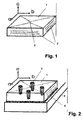
- FIG. 1 A Y123 superconductor in form of a plate is schematically shown in Figure 1.
- figure 1 1 denotes the textured YBCO superconductor with the cleavage planes parallel to the crystallographic ab axis' 2. Further, direction of axis' a, b and c are shown.
- FIG 2 an embodiment of the metal - ceramic ht superconductor composite of the present invention is shown schematically.
- the ceramic superconductor 1 is bonded by a bonding agent 6 to a metal support 4 in form of a plate.
- the present invention is applicable for bonding a ceramic superconductor to any type of metal support.
- the metal of which the support is made can be a metal of the iron group (Iron, Cobalt and Nickel) or any non iron group metal. Preferred are Cu, Al, Ni and stainless steel.
- the support can have the form of a plate, cylinder, tube etc.
- the superconductor 1 is bonded to the support 4 by soldering using the solders set out above.
- solders Preferably an indium solder or indium containing solder is used.
- the bonding agent 6 forms an intermediate layer covering the whole contact surface between the ceramic superconductor 1 and the metal support 4 as indicated in figure 2.
- the bonding agent 6 covers the contact surface only partially provided that the purpose of the present invention is met. In this case care has been taken that the bonding agent at the interface and the bonding agent filled into the through holes 5 are in contact with each other.
- the superconductor is provided with through holes 5, here four through holes are shown.
- the through holes 5 are vertically aligned with respect to the support 4 and with respect to the ab planes 2 of the Y123 superconductor.
- the through holes 5 are In communication with the bonding agent 6 at the interface between the superconductor 1 and the support 4.
- the through hole 5 can have also an inclined orientation with respect to the support.
- the through hole 5 are conically with the diameter decreasing towards the support.
- the conical form being preferred.
- an particularly intensive contact between the bonding agent and the inner surface of the through holes can be achieved.
- the bonding agent exhibits a higher thermal expansion coefficient than the superconductor material.
- a higher contraction of the bonding agent is achieved compared to the contraction of the superconductor material.
- the tensile force resulting from the contraction of the bonding agent acts directly on the wall of the preferably conically shaped through hole and results in an intensive contact between bonding agent and the htsc material over the whole temperature cycle during the cooling process.
- Figure 3 is a cross section along the line of two through holes 5 of figure 2 showing the continuous connection formed by the bonding agent 6 within the through holes 5 and the bonding agent 6 covering the interface between the ceramic superconductor 1 and the support 4.
- the direction of the tension executed by the bonding agent within the through holes 5 is indicated.
- a bonding agent should be applied having a thermal expansion coefficient being sufficiently higher than the thermal expansion coefficient of the superconductor material in order to ensure the generation of a sufficiently high tension perpendicular to said planes, e.g. in case of Y123 in direction of the c axis.
- Y123 superconductor in solder is a particularly suited bonding agent to this respect.
- the at least one through hole 5 within the superconductor 1 can be produced by any suitable method, such as drilling etc..
- the through holes 5 can be provided in the superconductor 1 after pressing, after sintering or after texturing of the sintered body.
- the through holes 5 are provided before the texturing. In this case the growing crystals will grow around the through holes 5.
- the surface of the superconductor adjacent to the support that is the surface by which the superconductor is bound to the support, and/or the inner surface of the wall of the through holes 5 can be completely or at least partially metalized by providing a thin metal layer thereon.
- the metalized layer can be provided by electrolyting surface coating or can be a burnt in metal layer such as a burnt In Silver layer. Materials and techniques for providing such burnt in metal layer into superconductors are generally known.
- the metal can be provided on the respective surfaces by means of spraying, immersing, brushing etc..
- holes or cavities are provided in the surface of the metal support 2 facing the superconductor 1.
- additional holes are filled with bonding agent resulting in an improvement of the stability of the composite as well as supporting the dissipation of heat.
- the location on the surface of the metal support, number, size and shape of these additional holes is not particularly restricted but can be chosen according to need.
- the holes can be located at any position on the support member. Preferably they are positioned opposite to an through hole 6.
- the holes are blind holes.
- the holes are of conical shape, in particular wherein the diameter increases towards the bottom of the holes. That is, the shape of the conical hole is the other way round as is the case of the preferred conical shape of the through holes.
- pins can be provided on the surface of the metal support projecting into the through holes 5 of the ceramic superconductor 1.
- the pins are made of a material having a good heat conductivity such as a metal or another material of good heat conductivity.
- the pins can be made from the same material than the metal support. By the provision of such pins the stability of the composite as well as dissipation of heat is improved.
- the number of that pins can be chosen according to need. For example there can be provided a pin for each through hole or the number of pins can be less than the number of the through holes 5.
- the diameter of the pins should be less than the diameter of the through holes so that in the inserted state a gap remains between the inner surface of the through holes and the surface of the pins large enough to ensure sufficient wetting by the solder.
- heat dissipation can be improved.
- Good heat dissipation is particularly required in applications such as fly wheels, electric motors and bearing housing for which the present invention can be advantageously used.
- a stoichiometric Y123 powder was mixed with 25 mol% Y 2 O 3 and 1 wt% CeO 2 .
- the powder was pressed into the form of a plate and sintered.
- a seed material of Sm 1 Ba 2 Cu 3 O 7 was placed on the top surface of the sintered body and texturing was carried out by heating the sintered body to a temperature above the melting point of the Y123, i.e. 1000 °C, but below the melting point of the seed material, i.e. 1080 °C, thereby melting the sintered body partially.
- the resulting s uperconductor body was mechanically finished by adjusting t he dimensions in accordance to the desired technical application. Further, the bottom surface of the superconductor body was smoothed for facilitating bonding to a support.
- the thus obtained shaped body was subjected to a heat treatment at 850°C at which the metal provided on the bottom surface of the shaped body was burnt into the shaped body thus forming a burnt in metal layer. Subsequently the temperature was decreased to 480 °C and held at 480 °C for 120 hours for adjusting the phase of the superconductor by oxygene absorption thereby inducing conversion of the phase from tetragonal to orthorhombic, that is from the non superconducting tetragonal phase to superconducting orthorhombic phase.
- An oxide layer formed on the surface of the silver layer during the above heat treatment was removed by a weak acid such as citric acid to ensure suitable bonding properties.
- the resulting superconductor body is soldered to the surface of a metal support by using indium s older, the surface of the metal support having been cleaned prior to soldering.
- the through holes within the superconductor body were completely filled with indium solder until an intimate contact was obtained with the solder at the interface between the bottom surface of the superconductor and the surface of the metal support.
- the resulting metal-ceramic superconductor composite could be cooled below critical temperature without any damage. No temperature gradient was observed.
- a YBCO 123 superconductor (1) is placed on a copper support (4) being bonded to each other by a soldering bonding using Biln (6).
- 0 through holes (5) are provided filled with Biln solder (6).
- the seed crystal (3) is still discemible.
- two bores (7) are provided for fixing means. The dimensions of the composite are as follows:
Landscapes
- Engineering & Computer Science (AREA)
- Chemical & Material Sciences (AREA)
- Ceramic Engineering (AREA)
- Manufacturing & Machinery (AREA)
- Materials Engineering (AREA)
- Structural Engineering (AREA)
- Organic Chemistry (AREA)
- Inorganic Chemistry (AREA)
- Ceramic Products (AREA)
- Superconductors And Manufacturing Methods Therefor (AREA)
- Inorganic Compounds Of Heavy Metals (AREA)
- Superconductor Devices And Manufacturing Methods Thereof (AREA)
Abstract
Description
For application the ceramic ht superconductor must be cooled below the critical temperature at which the ceramic material becomes superconducting. For most superconducting ceramic materials this critical temperature is extremely low.
According to another method the superconductor is linked to a cooling machine. in this case the superconductor must be connected to an efficient heat conductor in order to carry heat away from the superconductor.
Usually the heat conductor is made of metal and in the form of a plate or tube on which the superconductor is mounted and which is linked to the cooling machine. Suitable metals are Cu, Al, Nl, stainless steel, etc.
| heat conductivity λ[W/m • K] | heat expansion coefficient at room temperature α 10-5[1/K] | |
| copper | 384 | 1,68 |
| aluminium | 204 | 2,38 |
| YBCO ortho | 2 (c) / 10 (ab) | 0,3 (70 K) - 1,0 (300 K) |
On cooling shear stress is generated within the ab planes - aligned parallel to the copper plate - at the interface between the ceramic superconductor and the metal plate due to the different thermal expansion coefficient. Further, in the YBCO superconductor a temperature gradient of about 20 K occurs in direction of the c axis at a cooling temperature of 77 K
Both effects result in destruction, formation of cracks and separation of the superconductor in direction of the ab planes.
This is particularly problematical in superconductor materials of significant anisotropy such as YBCO.
As is clear the number and size of the through holes depend on the size of the superconductor body. Possible superconductor body can have sizes i n the in range from several mm up to more than 100 mm. Depending on the respective size of the superconductor body through holes can be prepared with diameters of smaller than 1mm up to more than 10 mm.
To the contrary in the hitherto known composites as discussed above wherein the bonding agent is present only at the interface between the superconductor and the metal support the binding is rigid thus allowing no sufficient compensation.
Such substituents and / or additives are well known to those skilled in the art.
- Figure 1
- an example of a superconductor suitable for the present invention;
- Figure 2
- a schematic view of the metal - ceramic ht superconductor composite according to the present invention;
- Figure 3
- a section through the composite of the present invention shown in figure 2; and
- Figure 4
- a photo of an embodiment of a metal-ceramic high temperature superconductor composite according to the present invention.
For example a suitable seed material for Y123 is Sm1Ba2Cu3O7 having a melting point of 1060 °C.
In figure 1 1 denotes the textured YBCO superconductor with the cleavage planes parallel to the crystallographic ab axis' 2. Further, direction of axis' a, b and c are shown.
The
Preferred are Cu, Al, Ni and stainless steel.
Preferably an indium solder or indium containing solder is used.
However if appropriate, it is also possible that the
The through
It is not necessary to fill the through holes completely with the bonding agent. However complete or approximately complete filling is preferred in order to ensure the generation of sufficiently high tension in direction along the through
On cooling due to the higher thermal expansion coefficient a higher contraction of the bonding agent is achieved compared to the contraction of the superconductor material. The tensile force resulting from the contraction of the bonding agent acts directly on the wall of the preferably conically shaped through hole and results in an intensive contact between bonding agent and the htsc material over the whole temperature cycle during the cooling process.
In figure 3 by the arrow on the right side directed towards the
The through
The metalized layer can be provided by electrolyting surface coating or can be a burnt in metal layer such as a burnt In Silver layer. Materials and techniques for providing such burnt in metal layer into superconductors are generally known.
For example the metal can be provided on the respective surfaces by means of spraying, immersing, brushing etc..
In the final composite also these additional holes are filled with bonding agent resulting in an improvement of the stability of the composite as well as supporting the dissipation of heat.
The holes can be located at any position on the support member. Preferably they are positioned opposite to an through
Preferably the holes are blind holes.
Preferably the holes are of conical shape, in particular wherein the diameter increases towards the bottom of the holes. That is, the shape of the conical hole is the other way round as is the case of the preferred conical shape of the through holes.
Preferably, the pins are made of a material having a good heat conductivity such as a metal or another material of good heat conductivity.
For example, the pins can be made from the same material than the metal support.
By the provision of such pins the stability of the composite as well as dissipation of heat is improved.
The number of that pins can be chosen according to need. For example there can be provided a pin for each through hole or the number of pins can be less than the number of the through holes 5.
Subsequently the temperature was decreased to 480 °C and held at 480 °C for 120 hours for adjusting the phase of the superconductor by oxygene absorption thereby inducing conversion of the phase from tetragonal to orthorhombic, that is from the non superconducting tetragonal phase to superconducting orthorhombic phase.
Further on the surface of the superconductor the seed crystal (3) is still discemible.
In the copper support (4) two bores (7) are provided for fixing means.
The dimensions of the composite are as follows:
- superconductor body (1) 37 mm breadth, 37 mm length and 12 mm height;
- support (4) 40 mm breadth, 100 mm length and 10 mm height.
- 1
- superconductor
- 2
- cleavage plane ab
- 3
- seed
- 4
- metal support
- 5
- through hole
- 6
- bonding agent
- 7
- bore
Claims (16)
- Metal-ceramic high temperature superconductor composite comprising a ceramic ht superconductor (1) bonded to a metal support (2) by a heat conductive bonding agent (3) wherein in the ceramic ht superconductor (1) at least one through hole (5) is provided being in communication to the bonding agent (6) at the interface between the metal support (2) and the ceramic ht superconductor (1), wherein further bonding agent ( 6) is provided in the at least one through hole (5) and wherein the bonding agent (6) at the interface and the bonding agent (6) in the at least one through hole (5) are in contact with each other.
- Metal-ceramic ht superconductor composite according to claim 1,
wherein
the at least one through hole (5) has a conical shape with the diameter decreasing toward the metal support (4). - Metal-ceramic ht superconductor composite according to claim 1 or claim 2,
wherein
the bonding between the superconductor (1) and the metal support (4) is selected from a group consisting of a solder bonding and a bonding by an adhesive system. - Metal-ceramic ht superconductor composite according to any of the preceding claims,
wherein
the superconductor is a REBa2Cu3O type superconductor with RE being Rare Earth Metal selected from Y, Pr, Nd. Sm. Eu, Gd, Tb, Dy. Ho, Er, Tm and Yb. - Metal-ceramic ht superconductor composite according to any of the preceding claims,
wherein
the bonding between superconductor (1) and the metal support (4) is a solder bonding and wherein the bottom surface of the superconductor (1) adjacent to the metal support (4) and/or the inner surface of the wall of the trough holes (5) are at least partially metalized. - Metal-ceramic ht superconductor composite according to any of the preceding claims,
wherein
the superconductor (1) is of REBa2CU3O type having a burnt In silver layer at its bottom surface and/or a burnt in silver layer at the inner surface of the wall of the through holes (5). - Metal ceramic ht superconductor composite according to any of the proceeding claims,
wherein
at least one hole is provided in the surface of the metal support (2) facing the superconductor (1). - Metal ceramic ht superconductor composite according to any of the proceeding claims,
wherein
at least one pin is provided on the surface of the metal support (2) projecting into a through hole (5). - Method for bonding a ceramic ht superconductor to a metal support wherein the ceramic ht superconductor (1) is bonded to a metal support (4), wherein the ceramic ht superconductor (1) is bonded to the metal support (4) by a heat conductive bonding agent (6), filling heat conductive bonding agent (6) into at least one through hole ( 5) provided in the ceramic ht superconductor (1), said bonding agent (6) at the interface between the metal support (4) and the ceramic ht superconductor and the bonding agent (6) within the at least one through hole (5) being in contact with each other.
- Method according to claim 9,
wherein
the at least one through hole (5) has a conical shape with a diameter decreasing towards the support (4). - Method according to claim 9 or claim 10,
wherein
the bonding of the superconductor (1) to the metal support (4) is carried out by soldering. - Method according to claim 9 or claim 10,
wherein
the bonding of the superconductor (1) to the metal support (4) is carried out by an adhesive system. - Method according to any of the claims 9 to 11,
wherein
the bottom surface of the superconductor (1) and/or the inner surface of the wall of the at least one trough hole (5) are at least partially metalized by applying a metal on the surface. - Method according to claim 13,
wherein
the metalization is carried out by forming a burnt in metal layer by applying metal on the surface to be metalized and subjecting the surface to heat treatment - Method according to any of the preceding claims 9 to 13,
wherein
the superconductor (1) is of REBa2Cu3O type with RE being Rare Earth Metal selected from the group consisting of Y, Pr, Nd, Sm, Eu, Gd, Tb, Dy, Ho, Er, Tm and Yb. - Use of a metal ceramic ht superconductor composite according to any of the claims 1 to 8 for flywheels, electric motors and bearing housing.
Priority Applications (1)
| Application Number | Priority Date | Filing Date | Title |
|---|---|---|---|
| EP20030292462 EP1406317B1 (en) | 2002-10-04 | 2003-10-06 | Metal-ceramic high temperature superconductor composite and process for bonding a ceramic high temperature superconductor to a metal |
Applications Claiming Priority (3)
| Application Number | Priority Date | Filing Date | Title |
|---|---|---|---|
| EP02292448 | 2002-10-04 | ||
| EP02292448 | 2002-10-04 | ||
| EP20030292462 EP1406317B1 (en) | 2002-10-04 | 2003-10-06 | Metal-ceramic high temperature superconductor composite and process for bonding a ceramic high temperature superconductor to a metal |
Publications (3)
| Publication Number | Publication Date |
|---|---|
| EP1406317A2 true EP1406317A2 (en) | 2004-04-07 |
| EP1406317A3 EP1406317A3 (en) | 2006-03-15 |
| EP1406317B1 EP1406317B1 (en) | 2008-09-03 |
Family
ID=32798728
Family Applications (1)
| Application Number | Title | Priority Date | Filing Date |
|---|---|---|---|
| EP20030292462 Expired - Lifetime EP1406317B1 (en) | 2002-10-04 | 2003-10-06 | Metal-ceramic high temperature superconductor composite and process for bonding a ceramic high temperature superconductor to a metal |
Country Status (6)
| Country | Link |
|---|---|
| US (2) | US7273569B2 (en) |
| EP (1) | EP1406317B1 (en) |
| JP (1) | JP2004158440A (en) |
| AT (1) | ATE407456T1 (en) |
| DE (1) | DE60323314D1 (en) |
| ES (1) | ES2312737T3 (en) |
Cited By (1)
| Publication number | Priority date | Publication date | Assignee | Title |
|---|---|---|---|---|
| WO2009073080A3 (en) * | 2007-11-29 | 2009-10-29 | Corning Incorporated | Method for bonding refractory ceramic and metal |
Families Citing this family (8)
| Publication number | Priority date | Publication date | Assignee | Title |
|---|---|---|---|---|
| DE10117370C2 (en) * | 2001-04-06 | 2003-05-22 | Vacuumschmelze Gmbh & Co Kg | Supraleiteranodnung |
| ES2356755T3 (en) * | 2006-11-17 | 2011-04-12 | Nexans | PROCEDURE FOR THE MANUFACTURE OF A SUPERCONDUCTIVE ELECTRIC DRIVER. |
| GB2453734B (en) * | 2007-10-16 | 2009-10-28 | Siemens Magnet Technology Ltd | Method for cooling superconductive joints |
| FR2993494B1 (en) * | 2012-07-18 | 2014-08-22 | Herakles | METHOD OF BRAZING PARTS OF COMPOSITE MATERIAL WITH ANCHORING OF THE BRAZE JOINT |
| WO2017040598A1 (en) * | 2015-08-31 | 2017-03-09 | Massachusetts Institute Of Technology | Systems and methods for hybrid superconducting medium |
| US10847706B2 (en) | 2015-09-01 | 2020-11-24 | Massachusetts Institute Of Technology | Systems and methods for hybrid superconducting medium comprising first and second layers with different superconductor to induce a proximity effect between thereof |
| KR20200099554A (en) * | 2017-12-14 | 2020-08-24 | 미합중국 (관리부서 : 미합중국 해군성) | Precise alignment and decal bonding of solder preforms to the pattern surface |
| JP7556801B2 (en) * | 2021-02-09 | 2024-09-26 | トヨタ自動車株式会社 | Stator and Busbar Modules |
Family Cites Families (11)
| Publication number | Priority date | Publication date | Assignee | Title |
|---|---|---|---|---|
| JPS59137378A (en) * | 1983-01-24 | 1984-08-07 | 三菱重工業株式会社 | Method of bonding ceramic or cermet and metal |
| JPH0776138B2 (en) * | 1986-12-23 | 1995-08-16 | 住友大阪セメント株式会社 | High thermal shock resistance joining method of ceramics and metal and joining product |
| JPS644029U (en) * | 1987-06-26 | 1989-01-11 | ||
| JPS6427166A (en) * | 1987-07-21 | 1989-01-30 | Toshiba Corp | Superconductive joint |
| JPS6428284A (en) * | 1987-07-21 | 1989-01-30 | Toshiba Corp | Oxide superconducting joint |
| DE4004908A1 (en) * | 1990-02-16 | 1991-08-22 | Daimler Benz Ag | Electrical conductor prodn. - by applying insulating oxide layer onto metallic conductor and depositing oxidic ceramic superconductor |
| JP2756363B2 (en) * | 1990-11-17 | 1998-05-25 | キヤノン株式会社 | Adhesive element |
| JPH04202068A (en) * | 1990-11-30 | 1992-07-22 | Hitachi Chem Co Ltd | Joined body of metallic plate and target for superconducting ceramics, production thereof and production of superconducting thin film |
| DE19746976C2 (en) * | 1997-10-24 | 2000-11-30 | Abb Research Ltd | High temperature superconductor arrangement |
| DE19832273C1 (en) * | 1998-07-17 | 1999-11-11 | Siemens Ag | Resistive current limiter e.g. for AC supply mains |
| JP2001114576A (en) * | 1999-10-15 | 2001-04-24 | Dowa Mining Co Ltd | Bonded body and oxide superconductor used for the same |
-
2003
- 2003-10-06 DE DE60323314T patent/DE60323314D1/en not_active Expired - Lifetime
- 2003-10-06 JP JP2003347425A patent/JP2004158440A/en active Pending
- 2003-10-06 ES ES03292462T patent/ES2312737T3/en not_active Expired - Lifetime
- 2003-10-06 AT AT03292462T patent/ATE407456T1/en not_active IP Right Cessation
- 2003-10-06 US US10/679,959 patent/US7273569B2/en not_active Expired - Fee Related
- 2003-10-06 EP EP20030292462 patent/EP1406317B1/en not_active Expired - Lifetime
-
2007
- 2007-09-07 US US11/899,973 patent/US20100041560A1/en not_active Abandoned
Cited By (4)
| Publication number | Priority date | Publication date | Assignee | Title |
|---|---|---|---|---|
| WO2009073080A3 (en) * | 2007-11-29 | 2009-10-29 | Corning Incorporated | Method for bonding refractory ceramic and metal |
| CN101925559A (en) * | 2007-11-29 | 2010-12-22 | 康宁股份有限公司 | Be used for the method for bonding refractory ceramic and metal |
| CN101925559B (en) * | 2007-11-29 | 2013-06-05 | 康宁股份有限公司 | Methods used to bond refractory ceramics and metals |
| US8899470B2 (en) | 2007-11-29 | 2014-12-02 | Corning Incorporated | Method for bonding refractory ceramic and metal |
Also Published As
| Publication number | Publication date |
|---|---|
| US20040162223A1 (en) | 2004-08-19 |
| ATE407456T1 (en) | 2008-09-15 |
| US20100041560A1 (en) | 2010-02-18 |
| EP1406317B1 (en) | 2008-09-03 |
| US7273569B2 (en) | 2007-09-25 |
| DE60323314D1 (en) | 2008-10-16 |
| JP2004158440A (en) | 2004-06-03 |
| ES2312737T3 (en) | 2009-03-01 |
| EP1406317A3 (en) | 2006-03-15 |
Similar Documents
| Publication | Publication Date | Title |
|---|---|---|
| US20100041560A1 (en) | Metal-ceramic high temperature superconductor composite and process for bonding a ceramic high temperature superconductor to a metal | |
| KR101242007B1 (en) | Two-sided splice for high temperature superconductor laminated wires | |
| EP0634379B1 (en) | Joined product of of superconductive oxide materials and its manufacture | |
| US5521150A (en) | Method of joining Y-based oxide superconductors | |
| JP5548441B2 (en) | Superconducting connection structure, superconducting wire connecting method, superconducting coil device | |
| JPH09306256A (en) | Bulk oxide superconductor and method of manufacturing wire and plate thereof | |
| JP4995284B2 (en) | Joining method of oxide superconductor tube and superconducting joint | |
| JP4113113B2 (en) | Oxide superconductor joining method and oxide superconductor joined body | |
| KR920005516B1 (en) | Method for producing an object with an oxide superconducting material | |
| US6561412B2 (en) | Method of joining together superconductors and a superconductor joined member produced by same | |
| JP2009170550A (en) | Oxide superconducting magnet, manufacturing method thereof, and cooling method | |
| JPH06231851A (en) | Method for making a conjugate of 123 superconductor segments | |
| Yan et al. | Progress of high-temperature superconducting joints | |
| EP1001472B1 (en) | Production method of joints of superconducting oxide and normal conductor | |
| JP4612311B2 (en) | Oxide superconductor current lead | |
| EP0284189B1 (en) | Method of manufacturing superconducting ceramics | |
| JP2001114576A (en) | Bonded body and oxide superconductor used for the same | |
| JP2779210B2 (en) | Conductor for current lead | |
| JPH0645140A (en) | Oxide superconductor current lead | |
| JPH05319824A (en) | Production of oxide superconductor laminated body | |
| Shimoyama | Melt processing techniques: melt process for BSCCO | |
| JPH0197321A (en) | Method for manufacturing superconducting members | |
| EP1001473A2 (en) | Superconducting system | |
| JP2000150972A (en) | Method of manufacturing oxide superconductor current lead | |
| Li | Fabrication and characterisation of novel substrates and superconducting thick films |
Legal Events
| Date | Code | Title | Description |
|---|---|---|---|
| PUAI | Public reference made under article 153(3) epc to a published international application that has entered the european phase |
Free format text: ORIGINAL CODE: 0009012 |
|
| AK | Designated contracting states |
Kind code of ref document: A2 Designated state(s): AT BE BG CH CY CZ DE DK EE ES FI FR GB GR HU IE IT LI LU MC NL PT RO SE SI SK TR |
|
| AX | Request for extension of the european patent |
Extension state: AL LT LV MK |
|
| PUAL | Search report despatched |
Free format text: ORIGINAL CODE: 0009013 |
|
| AK | Designated contracting states |
Kind code of ref document: A3 Designated state(s): AT BE BG CH CY CZ DE DK EE ES FI FR GB GR HU IE IT LI LU MC NL PT RO SE SI SK TR |
|
| AX | Request for extension of the european patent |
Extension state: AL LT LV MK |
|
| RIC1 | Information provided on ipc code assigned before grant |
Ipc: H01L 39/14 20060101ALI20060120BHEP Ipc: H01L 39/04 20060101AFI20060120BHEP |
|
| 17P | Request for examination filed |
Effective date: 20060915 |
|
| AKX | Designation fees paid |
Designated state(s): AT BE BG CH CY CZ DE DK EE ES FI FR GB GR HU IE IT LI LU MC NL PT RO SE SI SK TR |
|
| AXX | Extension fees paid |
Extension state: AL Payment date: 20060915 Extension state: MK Payment date: 20060915 Extension state: LV Payment date: 20060915 Extension state: LT Payment date: 20060915 |
|
| 17Q | First examination report despatched |
Effective date: 20070601 |
|
| GRAP | Despatch of communication of intention to grant a patent |
Free format text: ORIGINAL CODE: EPIDOSNIGR1 |
|
| GRAS | Grant fee paid |
Free format text: ORIGINAL CODE: EPIDOSNIGR3 |
|
| GRAA | (expected) grant |
Free format text: ORIGINAL CODE: 0009210 |
|
| AK | Designated contracting states |
Kind code of ref document: B1 Designated state(s): AT BE BG CH CY CZ DE DK EE ES FI FR GB GR HU IE IT LI LU MC NL PT RO SE SI SK TR |
|
| AX | Request for extension of the european patent |
Extension state: AL LT LV MK |
|
| REG | Reference to a national code |
Ref country code: GB Ref legal event code: FG4D |
|
| REG | Reference to a national code |
Ref country code: CH Ref legal event code: EP |
|
| REG | Reference to a national code |
Ref country code: IE Ref legal event code: FG4D |
|
| REF | Corresponds to: |
Ref document number: 60323314 Country of ref document: DE Date of ref document: 20081016 Kind code of ref document: P |
|
| LTIE | Lt: invalidation of european patent or patent extension |
Effective date: 20080903 |
|
| PG25 | Lapsed in a contracting state [announced via postgrant information from national office to epo] |
Ref country code: AT Free format text: LAPSE BECAUSE OF FAILURE TO SUBMIT A TRANSLATION OF THE DESCRIPTION OR TO PAY THE FEE WITHIN THE PRESCRIBED TIME-LIMIT Effective date: 20080903 Ref country code: FI Free format text: LAPSE BECAUSE OF FAILURE TO SUBMIT A TRANSLATION OF THE DESCRIPTION OR TO PAY THE FEE WITHIN THE PRESCRIBED TIME-LIMIT Effective date: 20080903 Ref country code: SI Free format text: LAPSE BECAUSE OF FAILURE TO SUBMIT A TRANSLATION OF THE DESCRIPTION OR TO PAY THE FEE WITHIN THE PRESCRIBED TIME-LIMIT Effective date: 20080903 |
|
| REG | Reference to a national code |
Ref country code: ES Ref legal event code: FG2A Ref document number: 2312737 Country of ref document: ES Kind code of ref document: T3 |
|
| PG25 | Lapsed in a contracting state [announced via postgrant information from national office to epo] |
Ref country code: BE Free format text: LAPSE BECAUSE OF FAILURE TO SUBMIT A TRANSLATION OF THE DESCRIPTION OR TO PAY THE FEE WITHIN THE PRESCRIBED TIME-LIMIT Effective date: 20080903 |
|
| PG25 | Lapsed in a contracting state [announced via postgrant information from national office to epo] |
Ref country code: BG Free format text: LAPSE BECAUSE OF FAILURE TO SUBMIT A TRANSLATION OF THE DESCRIPTION OR TO PAY THE FEE WITHIN THE PRESCRIBED TIME-LIMIT Effective date: 20081203 |
|
| PG25 | Lapsed in a contracting state [announced via postgrant information from national office to epo] |
Ref country code: PT Free format text: LAPSE BECAUSE OF FAILURE TO SUBMIT A TRANSLATION OF THE DESCRIPTION OR TO PAY THE FEE WITHIN THE PRESCRIBED TIME-LIMIT Effective date: 20090203 Ref country code: MC Free format text: LAPSE BECAUSE OF NON-PAYMENT OF DUE FEES Effective date: 20081031 Ref country code: SK Free format text: LAPSE BECAUSE OF FAILURE TO SUBMIT A TRANSLATION OF THE DESCRIPTION OR TO PAY THE FEE WITHIN THE PRESCRIBED TIME-LIMIT Effective date: 20080903 Ref country code: CZ Free format text: LAPSE BECAUSE OF FAILURE TO SUBMIT A TRANSLATION OF THE DESCRIPTION OR TO PAY THE FEE WITHIN THE PRESCRIBED TIME-LIMIT Effective date: 20080903 Ref country code: RO Free format text: LAPSE BECAUSE OF FAILURE TO SUBMIT A TRANSLATION OF THE DESCRIPTION OR TO PAY THE FEE WITHIN THE PRESCRIBED TIME-LIMIT Effective date: 20080903 |
|
| REG | Reference to a national code |
Ref country code: CH Ref legal event code: PL |
|
| PLBE | No opposition filed within time limit |
Free format text: ORIGINAL CODE: 0009261 |
|
| STAA | Information on the status of an ep patent application or granted ep patent |
Free format text: STATUS: NO OPPOSITION FILED WITHIN TIME LIMIT |
|
| PG25 | Lapsed in a contracting state [announced via postgrant information from national office to epo] |
Ref country code: EE Free format text: LAPSE BECAUSE OF FAILURE TO SUBMIT A TRANSLATION OF THE DESCRIPTION OR TO PAY THE FEE WITHIN THE PRESCRIBED TIME-LIMIT Effective date: 20080903 Ref country code: DK Free format text: LAPSE BECAUSE OF FAILURE TO SUBMIT A TRANSLATION OF THE DESCRIPTION OR TO PAY THE FEE WITHIN THE PRESCRIBED TIME-LIMIT Effective date: 20080903 |
|
| 26N | No opposition filed |
Effective date: 20090604 |
|
| PG25 | Lapsed in a contracting state [announced via postgrant information from national office to epo] |
Ref country code: CH Free format text: LAPSE BECAUSE OF NON-PAYMENT OF DUE FEES Effective date: 20081031 Ref country code: LI Free format text: LAPSE BECAUSE OF NON-PAYMENT OF DUE FEES Effective date: 20081031 Ref country code: IE Free format text: LAPSE BECAUSE OF NON-PAYMENT OF DUE FEES Effective date: 20081006 |
|
| PG25 | Lapsed in a contracting state [announced via postgrant information from national office to epo] |
Ref country code: SE Free format text: LAPSE BECAUSE OF FAILURE TO SUBMIT A TRANSLATION OF THE DESCRIPTION OR TO PAY THE FEE WITHIN THE PRESCRIBED TIME-LIMIT Effective date: 20081203 |
|
| PGFP | Annual fee paid to national office [announced via postgrant information from national office to epo] |
Ref country code: DE Payment date: 20091026 Year of fee payment: 7 Ref country code: ES Payment date: 20091023 Year of fee payment: 7 |
|
| PGFP | Annual fee paid to national office [announced via postgrant information from national office to epo] |
Ref country code: NL Payment date: 20091016 Year of fee payment: 7 |
|
| PGFP | Annual fee paid to national office [announced via postgrant information from national office to epo] |
Ref country code: FR Payment date: 20091110 Year of fee payment: 7 Ref country code: GB Payment date: 20091022 Year of fee payment: 7 Ref country code: IT Payment date: 20091024 Year of fee payment: 7 |
|
| PG25 | Lapsed in a contracting state [announced via postgrant information from national office to epo] |
Ref country code: HU Free format text: LAPSE BECAUSE OF FAILURE TO SUBMIT A TRANSLATION OF THE DESCRIPTION OR TO PAY THE FEE WITHIN THE PRESCRIBED TIME-LIMIT Effective date: 20090304 Ref country code: LU Free format text: LAPSE BECAUSE OF NON-PAYMENT OF DUE FEES Effective date: 20081006 Ref country code: CY Free format text: LAPSE BECAUSE OF FAILURE TO SUBMIT A TRANSLATION OF THE DESCRIPTION OR TO PAY THE FEE WITHIN THE PRESCRIBED TIME-LIMIT Effective date: 20080903 |
|
| PG25 | Lapsed in a contracting state [announced via postgrant information from national office to epo] |
Ref country code: TR Free format text: LAPSE BECAUSE OF FAILURE TO SUBMIT A TRANSLATION OF THE DESCRIPTION OR TO PAY THE FEE WITHIN THE PRESCRIBED TIME-LIMIT Effective date: 20080903 |
|
| PG25 | Lapsed in a contracting state [announced via postgrant information from national office to epo] |
Ref country code: GR Free format text: LAPSE BECAUSE OF FAILURE TO SUBMIT A TRANSLATION OF THE DESCRIPTION OR TO PAY THE FEE WITHIN THE PRESCRIBED TIME-LIMIT Effective date: 20081204 |
|
| REG | Reference to a national code |
Ref country code: NL Ref legal event code: V1 Effective date: 20110501 |
|
| GBPC | Gb: european patent ceased through non-payment of renewal fee |
Effective date: 20101006 |
|
| PG25 | Lapsed in a contracting state [announced via postgrant information from national office to epo] |
Ref country code: FR Free format text: LAPSE BECAUSE OF NON-PAYMENT OF DUE FEES Effective date: 20101102 |
|
| REG | Reference to a national code |
Ref country code: FR Ref legal event code: ST Effective date: 20110630 |
|
| PG25 | Lapsed in a contracting state [announced via postgrant information from national office to epo] |
Ref country code: GB Free format text: LAPSE BECAUSE OF NON-PAYMENT OF DUE FEES Effective date: 20101006 Ref country code: NL Free format text: LAPSE BECAUSE OF NON-PAYMENT OF DUE FEES Effective date: 20110501 |
|
| REG | Reference to a national code |
Ref country code: DE Ref legal event code: R119 Ref document number: 60323314 Country of ref document: DE Effective date: 20110502 |
|
| REG | Reference to a national code |
Ref country code: ES Ref legal event code: FD2A Effective date: 20111118 |
|
| PG25 | Lapsed in a contracting state [announced via postgrant information from national office to epo] |
Ref country code: IT Free format text: LAPSE BECAUSE OF NON-PAYMENT OF DUE FEES Effective date: 20101006 |
|
| PG25 | Lapsed in a contracting state [announced via postgrant information from national office to epo] |
Ref country code: ES Free format text: LAPSE BECAUSE OF NON-PAYMENT OF DUE FEES Effective date: 20101007 |
|
| PG25 | Lapsed in a contracting state [announced via postgrant information from national office to epo] |
Ref country code: DE Free format text: LAPSE BECAUSE OF NON-PAYMENT OF DUE FEES Effective date: 20110502 |