EP1406067B1 - Hochgenauer Hall-Sensor mit mehreren Kontaktpaaren - Google Patents
Hochgenauer Hall-Sensor mit mehreren Kontaktpaaren Download PDFInfo
- Publication number
- EP1406067B1 EP1406067B1 EP03009024.5A EP03009024A EP1406067B1 EP 1406067 B1 EP1406067 B1 EP 1406067B1 EP 03009024 A EP03009024 A EP 03009024A EP 1406067 B1 EP1406067 B1 EP 1406067B1
- Authority
- EP
- European Patent Office
- Prior art keywords
- hall
- sensor
- magnetic field
- contact pairs
- contacts
- Prior art date
- Legal status (The legal status is an assumption and is not a legal conclusion. Google has not performed a legal analysis and makes no representation as to the accuracy of the status listed.)
- Expired - Lifetime
Links
Images


Classifications
-
- G—PHYSICS
- G01—MEASURING; TESTING
- G01P—MEASURING LINEAR OR ANGULAR SPEED, ACCELERATION, DECELERATION, OR SHOCK; INDICATING PRESENCE, ABSENCE, OR DIRECTION, OF MOVEMENT
- G01P3/00—Measuring linear or angular speed; Measuring differences of linear or angular speeds
- G01P3/42—Devices characterised by the use of electric or magnetic means
- G01P3/44—Devices characterised by the use of electric or magnetic means for measuring angular speed
- G01P3/48—Devices characterised by the use of electric or magnetic means for measuring angular speed by measuring frequency of generated current or voltage
- G01P3/481—Devices characterised by the use of electric or magnetic means for measuring angular speed by measuring frequency of generated current or voltage of pulse signals
- G01P3/487—Devices characterised by the use of electric or magnetic means for measuring angular speed by measuring frequency of generated current or voltage of pulse signals delivered by rotating magnets
-
- G—PHYSICS
- G01—MEASURING; TESTING
- G01D—MEASURING NOT SPECIALLY ADAPTED FOR A SPECIFIC VARIABLE; ARRANGEMENTS FOR MEASURING TWO OR MORE VARIABLES NOT COVERED IN A SINGLE OTHER SUBCLASS; TARIFF METERING APPARATUS; MEASURING OR TESTING NOT OTHERWISE PROVIDED FOR
- G01D5/00—Mechanical means for transferring the output of a sensing member; Means for converting the output of a sensing member to another variable where the form or nature of the sensing member does not constrain the means for converting; Transducers not specially adapted for a specific variable
- G01D5/12—Mechanical means for transferring the output of a sensing member; Means for converting the output of a sensing member to another variable where the form or nature of the sensing member does not constrain the means for converting; Transducers not specially adapted for a specific variable using electric or magnetic means
- G01D5/14—Mechanical means for transferring the output of a sensing member; Means for converting the output of a sensing member to another variable where the form or nature of the sensing member does not constrain the means for converting; Transducers not specially adapted for a specific variable using electric or magnetic means influencing the magnitude of a current or voltage
- G01D5/142—Mechanical means for transferring the output of a sensing member; Means for converting the output of a sensing member to another variable where the form or nature of the sensing member does not constrain the means for converting; Transducers not specially adapted for a specific variable using electric or magnetic means influencing the magnitude of a current or voltage using Hall-effect devices
- G01D5/145—Mechanical means for transferring the output of a sensing member; Means for converting the output of a sensing member to another variable where the form or nature of the sensing member does not constrain the means for converting; Transducers not specially adapted for a specific variable using electric or magnetic means influencing the magnitude of a current or voltage using Hall-effect devices influenced by the relative movement between the Hall device and magnetic fields
Definitions
- the invention relates to a Hall sensor according to the preamble of patent claim 1.
- Magnetic field sensors are used in a variety of applications, e.g. Rotary movements and in particular rotation angle without contact to measure or control.
- An example from the automotive sector is the determination of the rate of rotation of an electric motor, the rotational frequency of a wheel in ABS applications or the measurement of the torque of a torsion bar in the steering column of a motor vehicle.
- FIG.1 shows an arrangement with a shaft 4 to which a flywheel 5 is fixed with permanent magnetic regions 6.
- a magnetic field sensor 7 is arranged stationary at a short distance.
- a magnetic field sensor for example, Hall sensors, magnetoresistive resistors, magnetotransistors, etc. can be used. If the shaft 4 rotates in the direction of the arrow A, then the magnetic field of the regions 6 and thus the angular position of the shaft 4 are detected by the sensor 7.
- Fig. 2 shows an enlarged view of the arrangement of Fig. 1 in which the magnetic field B generated by the magnetic regions 6 of the pole wheel 5 is indicated by curved arrows B.
- the MR sensor 7 (MR: magnetoresistive) comprises two MR sensor elements 8a, 8b, which are arranged with their sensitive axis at an angle of 90 ° to each other.
- MR sensors as in Fig. 2 are arranged, have the advantage that the cosine and sine component of the magnetic field B detected directly and from the calculation of the tangent of the rotation angle of the shaft 4 can be determined very accurately.
- the measured change in resistance of the MR sensor 7 is based on a rotation of the magnetic field relative to the sensitive axis of the sensor elements 8a, 8b.
- Hall elements are used as magnetic field sensors, which, in contrast to MR sensors, are easy to produce in most standard semiconductor processes. It is particularly advantageous here that the control and evaluation electronics together with the Hall sensors as ASIC, e.g. in a BCD process (bipolar CMOS DMOS), monolithically integrated on a chip. Thus, it is possible to produce an intelligent sensor with complete control and evaluation logic.
- Hall sensors however, have the disadvantage that they tend to drift the zero field offset (finite Hall voltage signal, even if no magnetic field is applied to the sensor).
- the offset is z.T. already incorporated in the Hall element during production and does not remain constant during the lifetime of the element. Remedy so-called Spinning-Currentoder "chopped" Hall elements with which the offset can be compensated.
- Fig. 3a and 3b show a spinning current Hall element in plan view and side view, respectively.
- the operating current I is in each case rotationally applied in a circle between two opposing contact diffusions 9 (arrow C) or else switched back and forth between orthogonal contact diffusions 9.
- the Hall voltage is applied to the two orthogonal to the current direction contact diffusions 9 and terminals 22 tapped.
- the 360 ° spinning operation compensates for asymmetric contributions and offset components in the measured Hall voltage.
- Fig. 3b shows again a cross section through a sensor chip 1 with different doping regions 3.
- the operating current I flows from a right contact area 9 to a left contact area 9, wherein the Hall voltage at the arranged perpendicular to the image plane contact areas 9 (not shown) is tapped.
- a Hall sensor for measuring angles of rotation or rotation rate which has a plurality of contact pairs for tapping a plurality of Hall voltages, from which an evaluation unit can determine an angular or rotational speed information EP 0 202 508 A1 a Hall sensor with multiple contacts, which are arranged on the surface of the sensor.
- the essential idea of the invention is to realize a Hall sensor which has a plurality of contact pairs, at which a plurality of Hall voltages (in one measurement or measuring position) are tapped. From this, an evaluation unit can again determine a rate of rotation or the angle at which the external magnetic field is directed to the sensor. Hall element and evaluation logic can be monolithically integrated on a chip.
- the contacts are preferably arranged around the operating current, offset from each other.
- the main advantage of this arrangement is that there is only a single Hall element that must be positioned relative to the magnetic field. This eliminates the previously required adjustment of several Hall elements.
- the sensor is independent of the absolute field strength and reacts only to the angle, but not to the strength of the magnetic field. The arrangement of the sensor relative to the magnetic field to be measured is therefore not critical.
- the Hall sensor preferably comprises at least two contact pairs with a total of at least three, preferably at least four Hall contacts for picking up at least two Hall voltages from which the angular or rotational speed information can be calculated.
- the two Hall voltages could each be measured between a contact located on the sensor and a reference potential.
- the contact of the reference potential does not necessarily have to be arranged on the sensor; an external reference potential is also possible.
- the Hall element is integrated in a chip, in which the Hall contacts are arranged on the surface of the chip and the operating current flows perpendicular to the surface through the chip.
- the contacts can optionally also be arranged peripherally on the chip or in the chip. In the latter case, the contacts would have to be led out of the chip.
- the contacts for tapping the Hall voltage are rotationally symmetrical about the central operating current around. This allows a particularly simple evaluation because of the same contact distances. Other arrangements of the contact positions are also conceivable.
- the contacts of the contact pairs are preferably arranged point-symmetrically about a common center.
- the angle of the external magnetic field is preferably determined by evaluating the Hall voltage of at least two contact pairs.
- the measurement of the Hall voltage at the contacts can be done either simultaneously or in chronological succession.
- the measurement of the Hall voltages is preferably carried out at two pairs of orthogonal contact. From this, the actual angle of the magnetic field can be determined in a particularly simple manner by forming the arc tangent. Of course, non-orthogonal pairs of contacts can be evaluated. In this case, however, additional computational effort is necessary to determine the angle.
- more than two, preferably all contact pairs of the Hall element are scanned during a measurement.
- offset contributions and asymmetries are also measured, which originate, for example, from an inaccurate, not completely symmetrical arrangement of the contacts. Such interference contributions can be eliminated or reduced relatively easily.
- Another possibility for correcting the measurement signals is to filter out the interference contributions contained in the measurement signal by means of a suitable filter.
- the adjusted measurement signal is finally used to evaluate the rotation angle, whereby the measurement accuracy can be further improved.
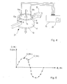
- Fig. 4 shows a magnetic field sensor with a Hall element 21, which is monolithically integrated into a chip together with an evaluation logic 15.
- the Hall element 21 consists of a substrate 17 on which a plurality of contacts 10a, 10b - 14a, 14b are arranged for picking up a Hall voltage.
- the operating current I is directed perpendicular to the chip surface 16 and is introduced into the substrate 17 via the contacts 18, 19.
- the operating current I is i.d.R. a DC current that flows from the front to the back of the chip or vice versa.
- a sinusoidal alternating current or a pulsed current may be used as the operating current.
- the Hall voltage is measured at the contacts 10a, 10b-14a, 14b arranged symmetrically about the central current flow I. Particularly advantageous in this case is a rotationally symmetrical arrangement of the contacts 10a, 10b-14a, 14b.
- other contact arrangements around the vertical current path such as e.g. an arrangement on the outer peripheral surface.
- the magnetic field sensor requires at least two pairs of contacts, at which at least two Hall voltages can be tapped.
- 16 contacts 10a, 10b - 14a, 14b are exemplarily drawn.
- the magnetic field B to be measured, for example, from a permanent magnet, as in Fig. 1 If the magnetic field B is oriented outside the chip plane 16, the magnetic field sensor detects only the corresponding portion of the magnetic field B running in the plane 16.
- the Hall voltage is advantageously measured at two orthogonally arranged contact pairs 10a, 10b, 14a, 14b.
- the measurement signal S ( ⁇ ) can also be applied to contact pairs 10a, 10b-14a, 14b are tapped, which are not arranged orthogonally.
- the evaluation in this case requires a higher computational effort.
- ⁇ is the angle relative to a predetermined reference direction, e.g. can be determined by any contact pair (10a, 10b).
- the offset in the measurement signal S ( ⁇ ) can thus be effectively reduced.
- the associated filter is preferably arranged in the evaluation unit 15.
- the interference contributions in the measurement signal can also be eliminated by means of another method, in which the operating current I is reversed in the opposite direction during the evaluation.
- the operating current I is reversed in the opposite direction during the evaluation.
Landscapes
- Physics & Mathematics (AREA)
- General Physics & Mathematics (AREA)
- Measuring Magnetic Variables (AREA)
- Transmission And Conversion Of Sensor Element Output (AREA)
Description
- Die Erfindung betrifft einen Hall-Sensor gemäß dem Oberbegriff des Patentanspruchs 1.
- Magnetfeldsensoren werden in einer Vielzahl von Anwendungen benutzt, um z.B. Drehbewegungen und insbesondere Drehwinkel berührungslos zu messen oder zu kontrollieren. Ein Beispiel aus dem Automobilbereich ist die Ermittlung der Drehrate eines Elektromotors, die Drehfrequenz eines Rades in ABS-Anwendungen oder die Messung des Drehmomentes einer Torsionsstange in der Lenksäule eines Kfz.
- Eine aus dem Stand der Technik bekannte Applikation mit Magnetfeldsensor ist in
Fig.1 dargestellt.Fig.1 zeigt eine Anordnung mit einer Welle 4, an der ein Polrad 5 mit permanent magnetischen Bereichen 6 befestigt ist. Am Aussenumfang des Polrades 5 ist in geringem Abstand ein Magnetfeldsensor 7 stationär angeordnet. Als Magnetfeldsensor können z.B. Hallsensoren, magnetoresistive Widerstände, Magnetotransistoren etc. verwendet werden. Dreht sich die Welle 4 in Richtung des Pfeils A, so wird das Magnetfeld der Bereiche 6 und somit die Winkelstellung der Welle 4 durch den Sensor 7 erfasst. -
Fig. 2 zeigt eine vergrößerte Ansicht der Anordnung vonFig. 1 , in der das von den magnetischen Bereichen 6 des Polrades 5 erzeugte magnetische Feld B durch gekrümmte Pfeile B angedeutet ist. Der MR-Sensor 7 (MR: magnetoresistiv) umfasst zwei MR-Sensorelemente 8a, 8b, die mit ihrer sensitiven Achse unter einem Winkel von 90° zueinander angeordnet sind. - MR-Sensoren, die wie in
Fig. 2 dargestellt angeordnet sind, haben den Vorteil, dass der Cosinus- und Sinus-Anteil des magnetischen Feldes B direkt erfasst und aus der Berechnung des Tangens der Drehwinkel der Welle 4 sehr genau bestimmt werden kann. Die gemessene Widerstandsänderung des MR-Sensors 7 beruht auf einer Drehung des Magnetfeldes relativ zur sensitiven Achse der Sensorelemente 8a, 8b. - Vorzugsweise werden jedoch Hall-Elemente als Magnetfeldsensoren verwendet, die im Gegensatz zu MR-Sensoren in den meisten Standard-Halbleiterprozessen einfach herstellbar sind. Besonders vorteilhaft ist hierbei, dass die Ansteuer- und Auswerteelektronik zusammen mit den Hall-Sensoren als ASIC, z.B. in einem BCD-Prozess (Bipolar-CMOS-DMOS), monolithisch auf einem Chip integriert werden kann. Somit ist es möglich, einen intelligenten Sensor mit kompletter Ansteuer- und Auswertelogik herzustellen.
- Hall-Sensoren haben jedoch den Nachteil, dass sie zum Driften des Nullfeld-Offsets (endliches Hall-Spannungssignal, auch wenn kein Magnetfeld am Sensor anliegt) neigen. Der Offset wird z.T. bereits bei der Herstellung im Hall-Element eingebaut und bleibt während der Lebensdauer des Elements nicht konstant. Abhilfe schaffen sogenannte Spinning-Currentoder "gechoppte" Hall-Elemente, mit denen der Offset kompensiert werden kann.
-
Fig. 3a und 3b zeigen ein Spinning-Current-Hall-Element in Draufsicht bzw. Seitenansicht. Der Betriebsstrom I wird dabei jeweils zwischen zwei gegenüberliegenden Kontaktdiffusionen 9 im Kreis rotierend angelegt (Pfeil C) oder auch nur zwischen orthogonalen Kontaktdiffusionen 9 hin und her geschaltet. Die Hall-Spannung wird dabei an den beiden orthogonal zur Stromrichtung liegenden Kontaktdiffusionen 9 bzw. Anschlüssen 22 abgegriffen. Durch den 360°-Spinning-Betrieb können asymmetrische Beiträge und Offsetkomponenten in der gemessenen Hall-Spannung kompensiert werden. -
Fig. 3b zeigt nochmals einen Querschnitt durch einen Sensorchip 1 mit verschieden Dotierbereichen 3. Der Betriebsstrom I fließt vom einem rechten Kontaktgebiet 9 zu einem linken Kontaktgebiet 9, wobei die Hall-Spannung an den senkrecht zur Bildebene angeordneten Kontaktgebieten 9 (nicht gezeigt) abgegriffen wird. - Eine hochgenaue Winkelmessung mit einem solchen Spinning-Current-Sensor ist jedoch kompliziert, da der Sensor nur auf Magnetfelder senkrecht zur Chipebene 16 sensitiv reagiert. Soll eine Winkelmessung wie in
Fig. 2 durchgeführt werden, müssten zwei separate Spinning-Current-Hall-Sensoren 1 in einem definierten Winkel zueinander angeordnet werden, um so die beiden entsprechenden Winkelkomponenten des Magnetfeldes B zu bestimmen. Dies erfordert höchste Justagegenauigkeit, um den Winkel zwischen den Hall-Sensoren 1 exakt einzustellen. Ferner ist es nur schwer möglich, die beiden Hall-Sensoren 1 so nahe beieinander anzuordnen, dass das Magnetfeld B hinreichend genau am selben Ort gemessen werden kann. Außerdem sind die beiden getrennten Hall-Sensoren 1 thermisch entkoppelt und können so zu unterschiedlichen thermischen Driften führen, was nur schwer kompensiert werden kann. - Aus der Zeitschrift Sensor Review, Vol. 18, Nr. 4, 1998, pp 252-257, C. Schottt et al.: "Modern integrated silicon Hall sensors" ist ein Hall-Sensor zum Messen von Drehwinkeln oder Drehraten bekannt, der mehrere Kontaktpaare zum Abgriff mehrerer Hall-Spannungen aufweist, aus denen eine Auswerteeinheit eine Winkel- oder Drehzahlinformation ermitteln kann. Ferner ist aus der
EP 0 202 508 A1 ein Hall-Sensor mit mehreren Kontakten bekannt, die an der Oberfläche des Sensors angeordnet sind. - Es ist daher die Aufgabe der vorliegenden Erfindung, einen Hall-Sensor zu schaffen, der wesentlich einfacher herzustellen ist und gleichzeitig eine hohe Messgenauigkeit bietet.
- Gelöst wird diese Aufgabe gemäß der Erfindung durch die im Patentanspruch 1 angegebenen Merkmale. Weitere Ausgestaltungen der Erfindung sind Gegenstand von Unteransprüchen.
- Der wesentliche Gedanke der Erfindung besteht darin, einen Hall-Sensor zu realisieren, der mehrere Kontaktpaare aufweist, an denen mehrere Hall-Spannungen (in einer Messung bzw. Messposition) abgegriffen werden. Daraus kann eine Auswerteeinheit wiederum eine Drehrate oder den Winkel ermitteln, in dem das äußere Magnetfeld auf den Sensor gerichtet ist. Hall-Element und Auswertelogik können dabei monolithisch auf einem Chip integriert sein. Die Kontakte sind vorzugsweise um den Betriebsstrom herum, versetzt zueinander angeordnet.
- Der wesentliche Vorteil dieser Anordnung besteht darin, dass nur ein einzelnes Hall-Element vorhanden ist, das relativ zum Magnetfeld positioniert werden muss. Somit entfällt die bisher erforderliche Justage mehrerer Hall-Elemente. Außerdem ist der Sensor bei Anwendung der erfindungsgemäßen Auswertemethode von der absoluten Feldstärke unabhängig und reagiert nur auf den Winkel, nicht dagegen auf die Stärke des Magnetfeldes. Die Anordnung des Sensors relativ zu dem zu messenden Magnetfeld ist daher unkritisch.
- Der Hall-Sensor umfasst vorzugsweise wenigstens zwei Kontaktpaare mit insgesamt wenigstens drei, vorzugsweise wenigstens vier Hall-Kontakten zum Abgreifen wenigstens zweier Hall-Spannungen, aus denen sich die Winkel- bzw. Drehzahlinformation errechnen lässt. Im Falle von drei Kontakten könnten die beiden Hall-Spannungen jeweils zwischen einem auf dem Sensor befindlichen Kontakt und einem Bezugspotential gemessen werden. Der Kontakt des Bezugspotentials muss nicht unbedingt ebenfalls auf dem Sensor angeordnet sein; ein externes Bezugspotential ist ebenfalls möglich.
- Gemäss einer bevorzugten Ausführungsform der Erfindung ist das Hall-Element in einem Chip integriert, bei dem die Hall-Kontakte auf der Oberfläche des Chips angeordnet sind und der Betriebsstrom senkrecht zur Oberfläche durch den Chip fließt.
- Auf diese Weise kann ein kostengünstiges Sensorelement in Standard-Halbleiterprozessen hergestellt werden. Die Kontakte können wahlweise auch umfangsseitig auf dem Chip oder im Chip angeordnet sein. Im letzteren Fall müssten die Kontakte aus dem Chip herausgeführt werden.
- Vorzugsweise sind die Kontakte für das Abgreifen der Hall-Spannung rotationssymmetrisch um den zentralen Betriebsstrom herum angeordnet. Dies ermöglicht wegen der gleich großen Kontaktabstände eine besonders einfache Auswertung. Andere Anordnungen der Kontaktpositionen sind gleichfalls denkbar. Die Kontakte der Kontaktpaare sind vorzugsweise punktsymmetrisch um einen gemeinsamen Mittelpunkt angeordnet.
- Der Winkel des äußeren Magnetfeldes wird vorzugsweise durch Auswertung der Hall-Spannung wenigstens zweier Kontaktpaare bestimmt. Die Messung der Hall-Spannung an den Kontakten kann entweder gleichzeitig oder zeitlich kurz nacheinander erfolgen.
- Die Messung der Hall-Spannungen erfolgt vorzugsweise an zwei orthogonal zueinander angeordneten Kontaktpaaren. Daraus läßt sich in besonders einfacher Weise durch Bildung des Arcustangens der aktuelle Winkel des Magnetfeldes bestimmen. Selbstverständlich können auch nicht-orthogonal zueinander liegende Kontaktpaare ausgewertet werden. In diesem Fall ist aber zusätzlicher Rechenaufwand zur Bestimmung des Winkels nötig.
- Gemäss einer bevorzugten Ausführungsform der Erfindung werden bei einer Messung mehr als zwei, vorzugsweise alle Kontaktpaare des Hall-Elements abgetastet. Dabei werden Offsetbeiträge und Asymmetrien mitgemessen, die beispielsweise von einer ungenauen, nicht vollständig symmetrischen Anordnung der Kontakte stammen. Derartige Störbeiträge können relativ einfach eliminiert bzw. reduziert werden:.
- Bei der Auswertung der Hall-Spannungen kann z.B. die Stromrichtung des Betriebsstroms umgekehrt und die Hall-Spannung an den Kontaktpaaren bei beiden Stromrichtungen gemessen werden. Dadurch lassen sich insbesondere von Hysterese-Effekten verursachte Offsetkomponenten eliminieren.
- Eine weitere Möglichkeit zur Korrektur der Messsignale besteht darin, die im Messsignal enthaltenen Störbeiträge mittels eines geeigneten Filters auszufiltern. Das bereinigte Messsignal wird schliesslich zur Auswertung des Drehwinkels herangezogen, wodurch die Messgenauigkeit noch weiter verbessert werden kann.
- Die Erfindung wird nachstehend anhand der beigefügten Zeichnungen beispielhaft näher erläutert. Es zeigen:
-
Fig. 1 eine schematische Darstellung einer Messanordnung mit einem MR-Magnetfeldsensor; -
Fig. 2 eine vergrößerte Darstellung des Polrades vonFig. 1 ; -
Fig. 3a, b verschiedene Ansichten eines bekannten Spinning-Current-Hall-Elements; -
Fig. 4 eine Ausführungsform eines hochgenauen Magnetfeldsensors gemäss der Erfindung; -
Fig. 5 eine mögliche Messkurve des Magnetfeldsensors vonFig. 4 ; und -
Fig. 6 ein Fourierspektrum eines Signals vonFig. 5 . - Bezüglich der Erläuterungen der
Fig. 1 ,2, 3a, und 3b wird auf die Beschreibungseinleitung verwiesen. -
Fig. 4 zeigt einen Magnetfeldsensor mit einem Hall-Element 21, das zusammen mit einer Auswertelogik 15 monolithisch in einen Chip integriert ist. Das Hall-Element 21 besteht aus einem Substrat 17, auf dem mehrere Kontakte 10a,10b - 14a,14b zum Abgreifen einer Hall-Spannung angeordnet sind. Der Betriebsstrom I ist senkrecht zur Chipoberfläche 16 gerichtet und wird über die Kontakte 18,19 in das Substrat 17 eingeleitet. - Der Betriebsstrom I ist i.d.R. ein Gleichstrom, der von der Vorder- zur Chiprückseite oder umgekehrt fließt. Wahlweise kann auch ein sinusförmiger Wechselstrom oder ein getakteter Strom als Betriebsstrom verwendet werden.
- Die Hall-Spannung wird an den symmetrisch um den zentralen Stromfluss I angeordneten Kontakten 10a,10b - 14a,14b gemessen. Besonders vorteilhaft ist hierbei eine rotationssymmetrische Anordnung der Kontakte 10a,10b-14a,14b. Denkbar sind jedoch auch andere Kontaktanordnungen um den vertikalen Strompfad, wie z.B. eine Anordnung auf der äußeren Umfangsfläche.
- Der Magnetfeldsensor benötigt wenigstens zwei Kontaktpaare, an denen wenigstens zwei Hallspannungen abgegriffen werden können. In der dargestellten Ausführungsform sind exemplarisch 16 Kontakte 10a,10b - 14a,14b gezeichnet.
- Das zu messende Magnetfeld B, das z.B. von einem Permanentmagneten, wie er in
Fig. 1 dargestellt ist, stammen kann, liegt parallel zur Chipebene 16. Ist das Magnetfeld B ausserhalb der Chipebene 16 orientiert, detektiert der Magnetfeldsensor nur den entsprechenden in der Ebene 16 verlaufenden Anteil des Magnetfeldes B. - Die Hall-Spannung wird vorteilhaft an zwei orthogonal angeordneten Kontaktpaaren 10a,10b;14a,14b gemessen. Wahlweise kann das Messsignal S(Φ) auch an Kontaktpaaren 10a,10b-14a,14b abgegriffen werden, die nicht orthogonal angeordnet sind. Die Auswertung erfordert in diesem Fall jedoch einen höheren Rechenaufwand.
- Bei einer Messung an zwei orthogonal angeordneten Kontaktpaaren 10a,10b - 14a,14b lässt sich der Winkel Φ des Magnetfeldes B unmittelbar aus folgender Beziehung ableiten:

- Hierbei ist Φ der Winkel relativ zu einer vorgegebenen Bezugsrichtung, die z.B. durch ein beliebiges Kontaktpaar (10a,10b) festgelegt werden kann.
- Durch Abtasten von mehr als zwei Kontaktpaaren, insbesondere sämtlicher Kontaktpaare 10a,10b - 14a,14b, ist es ferner möglich, Störbeiträge zu reduzieren bzw. im Idealfall zu eliminieren. Störbeiträge können beispielsweise durch Justagefehler der Kontakte 10a,10b-14a,14b, richtungsabhängige Stromtransporteigenschaften des Substrats 17 oder Hystereseeigenschaften entstehen, die zusätzliche Signalbeiträge liefern. Ein bevorzugtes Fehlerkompensationsverfahren wird nachfolgend anhand der
Fig. 5 und6 erläutert: -
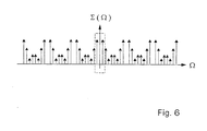
Fig. 5 zeigt das Messsignal S(Φk) an diskreten Messpunkten k, die durch die Anordnung der Kontakte 10a,10b - 14a,14b bestimmt sind. Wäre der Magnetfeldsensor ideal, so wäre S(Φ) sinusförmig und S(Φ k) wären Abtastpunkte auf der sinusförmigen Kurve. Wegen der genannten Störeffekte kommt es jedoch zu Abweichungen von der Idealkurve. -
Fig. 6 zeigt das zugehörige Signalspektrum ∑ (Ω) . Neben den eingerahmten Spektrallinien einer optimalen Sinuskurve sind periodisch wiederkehrende Signalanteile - die Störbeiträge - bei höheren Frequenzen zu erkennen. Durch eine geeignete Filterung ist es möglich, diese Störbeiträge zu unterdrücken. - Der Offset im Messsignal S(Φ) lässt sich somit wirkungsvoll reduzieren. Der zugehörige Filter ist vorzugsweise in der Auswerteeinheit 15 angeordnet.
- Durch die Filterung entsteht ein um Störbeiträge bereinigtes Signal Sf(Φk), aus dem der Winkel Φ des Magnetfeldes B in einfacher Weise nach folgender Beziehung abgeleitet werden kann:

- Wie erwähnt, können die Störbeiträge im Messsignal auch mittels einer anderen Methode eliminiert werden, bei der der Betriebsstrom I während der Auswertung in die Gegenrichtung umgepolt wird. Durch Messung der Hall-Spannung an einem Kontaktpaar 10a,10b-14a,14b jeweils bei Stromfluss in einer ersten Stromrichtung und der Gegenrichtung lassen sich asymmetrische Beiträge und Offsetkomponenten in einfacher Weise herausrechnen.
-
- 1
- Hall-Sensor
- 2
- Betriebsstrom
- 3
- Dotierbereiche
- 4
- Welle
- 5
- Polrad
- 6
- magnetische Bereiche
- 7
- Magnetfeldsensor
- 8a, 8b
- MR-Sensorelemente
- 9
- Kontaktdiffusionsgebiete
- 10a,b- 14a,b
- Kontakte
- 15
- Auswertelogik
- 16
- Chipoberfläche
- 17
- Substrat
- 18
- Vorderseitiger Kontakt
- 19
- Rückseitiger Kontakt
- 20
- Filter
- 21
- Hall-Sensor
- 22
- Anschlüsse
- S(Φ)
- Messsignal
Claims (3)
- Hall-Sensor, insbesondere für die Messung von Drehwinkeln oder Drehzahlen, in dem ein Betriebsstrom (1) fließt und , der mehrere Kontaktpaare (10a, 10b-14a, 14b) zum Abgriff mehrerer Hall-Spannungen bei Vorliegen eines magnetischen Feldes (B) aufweist, aus denen eine Auswerteeinheit (15) eine Winkel- oder Drehzahlinformation ermitteln kann, wobei die Kontaktpaare (10a, 10b-14a, 14b) an der Oberfläche (16) des Hall-Sensors (21) angeordnet sind, und der Betriebsstrom (1) senkrecht zur Oberfläche (16) durch den Sensor (21) fließt, dadurch gekennzeichnet, dass die Kontakte der Kontaktpaare (10a, 10b-14a, 14b) rotationssymmetrisch um den Betriebsstrom (1) herum angeordnet sind und dass die Hall-Spannungen an wenigstens zwei Kontaktpaaren (10a, 10b-14a, 14b) in derselben Messposition abgegriffen werden.
- Hall-Sensor nach Anspruch 1, dadurch gekennzeichnet, dass die einzelnen Hall-Spannungen gleichzeitig abgegriffen werden.
- Hall-Sensor nach einem der vorhergehenden Ansprüche, dadurch gekennzeichnet, dass die Auswerteeinheit (15) einen Filter (20) aufweist, mit dem Störbeiträge im Hall-Messsignal (S(D)) ausgefiltert werden, wobei das gesäuberte Messsignal (Sf (D)) zur Auswertung des Drehwinkels (c) oder der Drehrate herangezogen wird.
Applications Claiming Priority (2)
| Application Number | Priority Date | Filing Date | Title |
|---|---|---|---|
| DE10240239 | 2002-08-31 | ||
| DE2002140239 DE10240239A1 (de) | 2002-08-31 | 2002-08-31 | Hochgenauer Hall-Sensor mit mehreren Kontaktpaaren |
Publications (3)
| Publication Number | Publication Date |
|---|---|
| EP1406067A2 EP1406067A2 (de) | 2004-04-07 |
| EP1406067A3 EP1406067A3 (de) | 2006-06-14 |
| EP1406067B1 true EP1406067B1 (de) | 2013-10-09 |
Family
ID=31502211
Family Applications (1)
| Application Number | Title | Priority Date | Filing Date |
|---|---|---|---|
| EP03009024.5A Expired - Lifetime EP1406067B1 (de) | 2002-08-31 | 2003-04-17 | Hochgenauer Hall-Sensor mit mehreren Kontaktpaaren |
Country Status (2)
| Country | Link |
|---|---|
| EP (1) | EP1406067B1 (de) |
| DE (1) | DE10240239A1 (de) |
Families Citing this family (5)
| Publication number | Priority date | Publication date | Assignee | Title |
|---|---|---|---|---|
| ES2676508T3 (es) * | 2007-06-06 | 2018-07-20 | Hydro-Aire, Inc. | Sensor de posición angular |
| WO2009052537A1 (en) | 2007-10-25 | 2009-04-30 | Sensordynamics Ag Entwicklungs- Und Produktionsgesellschaft | Method and device for contactless sensing rotation and angular position using orientation tracking |
| EP2500698B1 (de) * | 2011-03-18 | 2014-02-12 | SICK STEGMANN GmbH | Vorrichtung und Verfahren zur Messung des Drehwinkels zweier relativ zueinander rotierender Objekte |
| DE102014112299B4 (de) * | 2014-08-27 | 2025-07-10 | Tdk Electronics Ag | Stromsensor und Schaltungsanordnung mit einem Wandler und einem Stromsensor |
| CN115754332A (zh) * | 2022-11-08 | 2023-03-07 | 深圳市麦普克斯机电设备有限公司 | 霍尔式复合信号速度传感器 |
Citations (1)
| Publication number | Priority date | Publication date | Assignee | Title |
|---|---|---|---|---|
| EP0202508A1 (de) * | 1985-05-22 | 1986-11-26 | LGZ LANDIS & GYR ZUG AG | Einrichtung mit einem in einer integrierten Schaltung integrierbaren Hallelement |
Family Cites Families (4)
| Publication number | Priority date | Publication date | Assignee | Title |
|---|---|---|---|---|
| GB1141524A (en) * | 1966-03-22 | 1969-01-29 | Standard Telephones Cables Ltd | Information link for high voltage power lines |
| DE19839446A1 (de) * | 1998-08-29 | 2000-03-02 | Bosch Gmbh Robert | Anordnung zur Drehwinkelerfassung eines drehbaren Elements |
| US6580269B2 (en) * | 2000-04-14 | 2003-06-17 | Melexis Uk Ltd. | Magnetic sensing devices and systems |
| DE10137294A1 (de) * | 2000-08-02 | 2002-03-14 | Continental Teves Ag & Co Ohg | Kraftfahrzeugmagnetfeldsensoranordnung, Aktivsensor, dessen Verwendung, Verfahren und Vorrichtung |
-
2002
- 2002-08-31 DE DE2002140239 patent/DE10240239A1/de not_active Withdrawn
-
2003
- 2003-04-17 EP EP03009024.5A patent/EP1406067B1/de not_active Expired - Lifetime
Patent Citations (1)
| Publication number | Priority date | Publication date | Assignee | Title |
|---|---|---|---|---|
| EP0202508A1 (de) * | 1985-05-22 | 1986-11-26 | LGZ LANDIS & GYR ZUG AG | Einrichtung mit einem in einer integrierten Schaltung integrierbaren Hallelement |
Also Published As
| Publication number | Publication date |
|---|---|
| EP1406067A3 (de) | 2006-06-14 |
| DE10240239A1 (de) | 2004-03-11 |
| EP1406067A2 (de) | 2004-04-07 |
Similar Documents
| Publication | Publication Date | Title |
|---|---|---|
| DE102009038256B4 (de) | Winkelpositionsmesssystem, Verfahren zum Messen einer Winkelposition und Drehmomentsensor | |
| DE60200499T2 (de) | Stellungsfühler, besonders zur Feststellung von Verdrehung einer Lenksäule | |
| EP2396666B1 (de) | Anordnung zur messung mindestens einer komponente eines magnetfeldes | |
| EP2979102B1 (de) | Fremdmagnetfeld-unempfindlicher hallsensor | |
| EP3224639B1 (de) | Magnetoresistive wheatstone-messbrücke und winkelsensor mit zumindest zwei derartigen messbrücken | |
| EP2340413B1 (de) | Messvorrichtung zur erfassung einer relativbewegung | |
| EP1049908A1 (de) | Anordnung zur drehwinkelerfassung eines drehbaren elements | |
| DE19543562A1 (de) | Anordnung zur berührungslosen Drehwinkelerfassung eines drehbaren Elements | |
| EP4176271B1 (de) | Omnidirektionaler drehzahl- und richtungssensor | |
| EP2037286A1 (de) | Messvorrichtung zur Messung eines magnetischen Felds | |
| DE102019006138B3 (de) | Integrierte Drehwinkelbestimmungssensoreinheit in einem Messsystem zur Drehwinkelbestimmung | |
| WO2017140495A1 (de) | Anordnung zur erfassung der winkelposition eines drehbaren bauteils | |
| DE102010032061A1 (de) | Vorrichtung zur Messung eines Drehwinkels und/oder eines Drehmoments | |
| DE69413670T2 (de) | Messvorrichtung zur differentiellen messung von momenten | |
| WO2018177762A1 (de) | Störfeldkompensierte winkelsensorvorrichtung und verfahren zur störfeldkompensierten winkelbestimmung | |
| DE112022006123T5 (de) | Magnetsensorsystem | |
| WO2011076554A1 (de) | Sensoranordnung zur kombinierten drehzahl-drehmoment-erfassung | |
| WO2016150616A1 (de) | Sensoranordnung zur drehzahlerfassung eines rotierenden bauteils | |
| EP1406067A2 (de) | Hochgenauer Hall-Sensor mit mehreren Kontaktpaaren | |
| EP3839442B1 (de) | Vorrichtung und korrekturverfahren zur automatischen berechnung von korrekturwerten für die winkelmesswerte eines drehgebers sowie drehgeber | |
| DE102016103518B4 (de) | Verfahren und Vorrichtung zur Rotorlagendiagnose in einem elektromotorischen Antrieb | |
| DE102012203158A1 (de) | Vorrichtung und Verfahren zur absoluten Winkelpositionsbestimmung eines drehbaren Körpers mittels zweier normal zur Drehachse angebrachter Sensoren | |
| DE102017211991B3 (de) | Anordnung zur Erfassung der Winkelposition eines drehbaren Bauteils | |
| DE102019005876A1 (de) | Integrierte Drehwinkelbestimmungssensoreinheit in einem Messsystem zur Drehwinkelbestimmung | |
| DE4313556C2 (de) | Vorrichtung und Verfahren zur berührungslosen Messung von Drehmomenten an Wellen |
Legal Events
| Date | Code | Title | Description |
|---|---|---|---|
| PUAI | Public reference made under article 153(3) epc to a published international application that has entered the european phase |
Free format text: ORIGINAL CODE: 0009012 |
|
| AK | Designated contracting states |
Kind code of ref document: A2 Designated state(s): AT BE BG CH CY CZ DE DK EE ES FI FR GB GR HU IE IT LI LU MC NL PT RO SE SI SK TR |
|
| AX | Request for extension of the european patent |
Extension state: AL LT LV MK |
|
| PUAL | Search report despatched |
Free format text: ORIGINAL CODE: 0009013 |
|
| AK | Designated contracting states |
Kind code of ref document: A3 Designated state(s): AT BE BG CH CY CZ DE DK EE ES FI FR GB GR HU IE IT LI LU MC NL PT RO SE SI SK TR |
|
| AX | Request for extension of the european patent |
Extension state: AL LT LV MK |
|
| 17P | Request for examination filed |
Effective date: 20061214 |
|
| AKX | Designation fees paid |
Designated state(s): CH DE FR GB IT LI |
|
| 17Q | First examination report despatched |
Effective date: 20101125 |
|
| GRAP | Despatch of communication of intention to grant a patent |
Free format text: ORIGINAL CODE: EPIDOSNIGR1 |
|
| INTG | Intention to grant announced |
Effective date: 20130703 |
|
| INTG | Intention to grant announced |
Effective date: 20130709 |
|
| GRAS | Grant fee paid |
Free format text: ORIGINAL CODE: EPIDOSNIGR3 |
|
| GRAA | (expected) grant |
Free format text: ORIGINAL CODE: 0009210 |
|
| AK | Designated contracting states |
Kind code of ref document: B1 Designated state(s): CH DE FR GB IT LI |
|
| REG | Reference to a national code |
Ref country code: GB Ref legal event code: FG4D Free format text: NOT ENGLISH |
|
| REG | Reference to a national code |
Ref country code: CH Ref legal event code: EP |
|
| REG | Reference to a national code |
Ref country code: DE Ref legal event code: R096 Ref document number: 50314909 Country of ref document: DE Effective date: 20131205 |
|
| REG | Reference to a national code |
Ref country code: DE Ref legal event code: R097 Ref document number: 50314909 Country of ref document: DE |
|
| PGFP | Annual fee paid to national office [announced via postgrant information from national office to epo] |
Ref country code: GB Payment date: 20140423 Year of fee payment: 12 |
|
| PLBE | No opposition filed within time limit |
Free format text: ORIGINAL CODE: 0009261 |
|
| STAA | Information on the status of an ep patent application or granted ep patent |
Free format text: STATUS: NO OPPOSITION FILED WITHIN TIME LIMIT |
|
| PG25 | Lapsed in a contracting state [announced via postgrant information from national office to epo] |
Ref country code: IT Free format text: LAPSE BECAUSE OF FAILURE TO SUBMIT A TRANSLATION OF THE DESCRIPTION OR TO PAY THE FEE WITHIN THE PRESCRIBED TIME-LIMIT Effective date: 20131009 |
|
| PGFP | Annual fee paid to national office [announced via postgrant information from national office to epo] |
Ref country code: FR Payment date: 20140416 Year of fee payment: 12 Ref country code: DE Payment date: 20140626 Year of fee payment: 12 |
|
| 26N | No opposition filed |
Effective date: 20140710 |
|
| REG | Reference to a national code |
Ref country code: DE Ref legal event code: R097 Ref document number: 50314909 Country of ref document: DE Effective date: 20140710 |
|
| REG | Reference to a national code |
Ref country code: CH Ref legal event code: PL |
|
| PG25 | Lapsed in a contracting state [announced via postgrant information from national office to epo] |
Ref country code: LI Free format text: LAPSE BECAUSE OF NON-PAYMENT OF DUE FEES Effective date: 20140430 Ref country code: CH Free format text: LAPSE BECAUSE OF NON-PAYMENT OF DUE FEES Effective date: 20140430 |
|
| REG | Reference to a national code |
Ref country code: DE Ref legal event code: R119 Ref document number: 50314909 Country of ref document: DE |
|
| GBPC | Gb: european patent ceased through non-payment of renewal fee |
Effective date: 20150417 |
|
| PG25 | Lapsed in a contracting state [announced via postgrant information from national office to epo] |
Ref country code: DE Free format text: LAPSE BECAUSE OF NON-PAYMENT OF DUE FEES Effective date: 20151103 Ref country code: GB Free format text: LAPSE BECAUSE OF NON-PAYMENT OF DUE FEES Effective date: 20150417 |
|
| REG | Reference to a national code |
Ref country code: FR Ref legal event code: ST Effective date: 20151231 |
|
| PG25 | Lapsed in a contracting state [announced via postgrant information from national office to epo] |
Ref country code: FR Free format text: LAPSE BECAUSE OF NON-PAYMENT OF DUE FEES Effective date: 20150430 |