EP1405992B1 - Regelsystem zur Regelung eines Kühlungssystems einer Brennkraftmaschine eines Kraftfahrzeugs - Google Patents
Regelsystem zur Regelung eines Kühlungssystems einer Brennkraftmaschine eines Kraftfahrzeugs Download PDFInfo
- Publication number
- EP1405992B1 EP1405992B1 EP03022279A EP03022279A EP1405992B1 EP 1405992 B1 EP1405992 B1 EP 1405992B1 EP 03022279 A EP03022279 A EP 03022279A EP 03022279 A EP03022279 A EP 03022279A EP 1405992 B1 EP1405992 B1 EP 1405992B1
- Authority
- EP
- European Patent Office
- Prior art keywords
- control system
- engine
- des
- cooling fluid
- value
- Prior art date
- Legal status (The legal status is an assumption and is not a legal conclusion. Google has not performed a legal analysis and makes no representation as to the accuracy of the status listed.)
- Expired - Lifetime
Links
- 238000001816 cooling Methods 0.000 title claims description 14
- 239000012809 cooling fluid Substances 0.000 claims description 22
- 239000002184 metal Substances 0.000 claims description 15
- 230000001276 controlling effect Effects 0.000 claims description 7
- 230000001105 regulatory effect Effects 0.000 claims description 7
- 101100452236 Caenorhabditis elegans inf-1 gene Proteins 0.000 claims description 5
- 238000002485 combustion reaction Methods 0.000 claims description 5
- 238000013178 mathematical model Methods 0.000 claims description 5
- 239000012530 fluid Substances 0.000 claims description 2
- 238000005259 measurement Methods 0.000 claims 1
- 239000000498 cooling water Substances 0.000 description 22
- XLYOFNOQVPJJNP-UHFFFAOYSA-N water Substances O XLYOFNOQVPJJNP-UHFFFAOYSA-N 0.000 description 7
- 239000003921 oil Substances 0.000 description 5
- 238000004364 calculation method Methods 0.000 description 2
- 238000009472 formulation Methods 0.000 description 2
- 239000000203 mixture Substances 0.000 description 2
- 230000001419 dependent effect Effects 0.000 description 1
- 238000010438 heat treatment Methods 0.000 description 1
- 239000010705 motor oil Substances 0.000 description 1
- 230000010355 oscillation Effects 0.000 description 1
- 230000003134 recirculating effect Effects 0.000 description 1
Images


Classifications
-
- F—MECHANICAL ENGINEERING; LIGHTING; HEATING; WEAPONS; BLASTING
- F01—MACHINES OR ENGINES IN GENERAL; ENGINE PLANTS IN GENERAL; STEAM ENGINES
- F01P—COOLING OF MACHINES OR ENGINES IN GENERAL; COOLING OF INTERNAL-COMBUSTION ENGINES
- F01P7/00—Controlling of coolant flow
- F01P7/14—Controlling of coolant flow the coolant being liquid
- F01P7/16—Controlling of coolant flow the coolant being liquid by thermostatic control
- F01P7/167—Controlling of coolant flow the coolant being liquid by thermostatic control by adjusting the pre-set temperature according to engine parameters, e.g. engine load, engine speed
-
- F—MECHANICAL ENGINEERING; LIGHTING; HEATING; WEAPONS; BLASTING
- F01—MACHINES OR ENGINES IN GENERAL; ENGINE PLANTS IN GENERAL; STEAM ENGINES
- F01P—COOLING OF MACHINES OR ENGINES IN GENERAL; COOLING OF INTERNAL-COMBUSTION ENGINES
- F01P2023/00—Signal processing; Details thereof
-
- F—MECHANICAL ENGINEERING; LIGHTING; HEATING; WEAPONS; BLASTING
- F01—MACHINES OR ENGINES IN GENERAL; ENGINE PLANTS IN GENERAL; STEAM ENGINES
- F01P—COOLING OF MACHINES OR ENGINES IN GENERAL; COOLING OF INTERNAL-COMBUSTION ENGINES
- F01P2025/00—Measuring
- F01P2025/08—Temperature
- F01P2025/46—Engine parts temperature
-
- F—MECHANICAL ENGINEERING; LIGHTING; HEATING; WEAPONS; BLASTING
- F01—MACHINES OR ENGINES IN GENERAL; ENGINE PLANTS IN GENERAL; STEAM ENGINES
- F01P—COOLING OF MACHINES OR ENGINES IN GENERAL; COOLING OF INTERNAL-COMBUSTION ENGINES
- F01P2025/00—Measuring
- F01P2025/60—Operating parameters
-
- F—MECHANICAL ENGINEERING; LIGHTING; HEATING; WEAPONS; BLASTING
- F01—MACHINES OR ENGINES IN GENERAL; ENGINE PLANTS IN GENERAL; STEAM ENGINES
- F01P—COOLING OF MACHINES OR ENGINES IN GENERAL; COOLING OF INTERNAL-COMBUSTION ENGINES
- F01P2025/00—Measuring
- F01P2025/60—Operating parameters
- F01P2025/64—Number of revolutions
-
- F—MECHANICAL ENGINEERING; LIGHTING; HEATING; WEAPONS; BLASTING
- F01—MACHINES OR ENGINES IN GENERAL; ENGINE PLANTS IN GENERAL; STEAM ENGINES
- F01P—COOLING OF MACHINES OR ENGINES IN GENERAL; COOLING OF INTERNAL-COMBUSTION ENGINES
- F01P2025/00—Measuring
- F01P2025/60—Operating parameters
- F01P2025/66—Vehicle speed
Definitions
- the present invention relates to a control system for controlling a vehicle engine cooling system.
- Known cooling systems supply cooling water to an internal combustion engine, which in turn supplies water to the inlet of a radiator via a thermostatic control valve, and the water from the radiator is pumped back into the engine.
- the control valve also recirculates part of the water from the engine along a bypass conduit extending from the control valve to the engine cooling water inlet; and, before the water is recirculated, parallel branches may supply other user devices, such as the exhaust gas cooler before recirculation, passenger compartment heater, engine oil cooler, etc., see for example JP 05 231 149 A .
- the cooling water temperature is regulated solely by the thermostatic valve, which is by nature extremely inaccurate (some known thermostatic valves, for example, operate on the basis of wax expansion, a poorly repeatable phenomenon which is difficult to control.
- a control system for controlling a cooling system of a vehicle engine, wherein an internal combustion engine receives a stream F a of cooling fluid, and supplies a stream of fluid F u to the inlet of at least a radiator via regulating means controllable by a drive signal; said control system being characterized by comprising: a closed-loop control system, which receives a reference signal T des related to a desired operating temperature of the engine, and a signal T mis representing a measured operating temperature of the engine, said closed-loop control system generating a first component P cl_loop of said drive signal; and an open-loop control system, which receives at least said reference signal T des , and generates a second component P op_loop of said drive signal by means of a model representing the inverse engine-radiator thermal system.
- the temperature of the cooling fluid thus converges to the reference temperature.
- Number 1 in Figure 1 indicates as a whole a control system for controlling a cooling system 2 connected to an internal combustion engine 3 of a vehicle (not shown).
- Internal combustion engine 3 receives a stream F a of cooling fluid (water for instance in the described example), and supplies a stream of water F u to the inlet of a radiator 4 via a control valve 5.
- Radiator 4 in turn supplies a stream of water which is pumped back along a conduit 6 to engine 3 by a pump 7.
- Control valve 5 (known type) also recirculates part of stream F u along a recirculating conduit 9 extending from control valve 5 to the engine cooling water inlet.
- Control valve 5 operates under control of an actuator 10, which receives a drive signal P from an electronic central control unit 12.
- Electronic central control unit 12 generates the drive signal by means of a closed-loop control system 14 and an open-loop control system 15.
- closed-loop control system 14 comprises an adding node 17, to which are supplied, with opposite signs, a signal related to the measured operating temperature of the engine, in particular a signal representing the measured temperature T mis of cooling water stream F u at the outlet of engine 3, and a reference signal T des representing a desired target operating temperature of the engine, in particular a target temperature of the stream of cooling water.
- Adding node 17 generates an error signal T des -T mis , which is supplied to a controller block 20 (e.g. a PID block) to generate a first drive signal component P cl_loop which in turn is supplied to an adding node 22.
- a controller block 20 e.g. a PID block
- the measured operating temperature of the engine may be defined by the temperature, measured at characteristic points on the engine, of the metal from which the engine is made; in which case, the reference temperature represents a target temperature of characteristic points of the engine.
- a second drive signal component P op_loop is supplied by open-loop control system 15, which receives information relating to reference signal T des , and generates the second component P op_loop by means of a mathematical model representing the inverse engine-radiator thermal system.
- Open-loop control system 15 comprises a number of blocks which together define a model of the engine-radiator thermal system.
- open-loop control system 15 comprises a first block 30 (detailed below), which receives the desired engine operating temperature value T des (i.e. the desired cooling water temperature or the desired metal temperature at given points on the engine), and generates the estimated value of a coefficient Kr representing, in an appropriate model, the heat exchange performance of the radiator required to maintain the desired temperature value T des .
- T des i.e. the desired cooling water temperature or the desired metal temperature at given points on the engine
- Open-loop control system 15 comprises a second block 40, which receives the estimated value of coefficient Kr, and generates the value of the cooling water flow Qf which must be physically circulated in radiator 4 to maintain the desired temperature value T des .
- the cooling water flow value is expressed as a function of the radiator fan operating state (on/off), and possibly fan speed in the case of electric fans with continuous or step speed adjustment.
- Open-loop control system 15 comprises a third block 50, which receives the calculated cooling water flow value Qf and information relating to the fan on/off state or fan speed in the case of continuous or step speed adjustment.
- block 50 calculates, on the basis of the information received, the opening value ⁇ of control valve 5 required to maintain the desired temperature value T des .
- valve opening value refers not only to valve 5 in the Figure 1 embodiment, but also to the auxiliary valves (not shown in Figure 1 for the sake of simplicity) controlling cooling water flow in the various branches of the cooling circuit. Variations in the opening or closure of the auxiliary valves, in fact, affects cooling water flow to radiator 4.
- the above calculation is performed using an appropriate table, which supplies an opening value ⁇ of valve 5 (and any auxiliary valves) for each input value Qf.
- the first variation is advantageously used when the speed of pump 7 cannot be adjusted independently, in which case, flow can only be regulated by working on the opening of control valve 5 (and any auxiliary valves).
- block 50 calculates, on the basis of the information received, the pump speed ⁇ and the opening ⁇ of valve 5 (and any auxiliary valves) which together provide for maintaining the desired temperature value T des .
- the pump speed and opening of valve 5 are selected to maximize a given requirement, such as minimizing consumption or reducing noise.
- the second variation is advantageously used when pump 7 allows of independent speed adjustment, in which case, flow can be regulated by working both on the opening of control valve 5 (and any auxiliary valves) and on the speed of the pump (electrically powered, program-powered by the drive shaft via friction wheels, electromagnetic clutches, etc..).
- Equation (1) as shown above may obviously be based on a subset of the above nine input variables.
- Equation (1) may be derived from analytical formulation, or from a test-based data table, or from a combination of the two.
- engine sensor readings or information derived from processing them
- the parameters of equation (1) can be updated continuously, or in predetermined time steps, or with reference to mileage, or on command.
- K r K cc + S h ⁇ H h ⁇ T ⁇ m - T des T des - T 0 - 1 L 0 ⁇ d T des d t
- Equation (2) as shown above may obviously be based on a subset of the above twelve input variables.
- Equation (2) may be derived from a mathematical model, which determines the metal temperature at various characteristic points of the engine, or from a table of values memorized beforehand on the basis of test results, or from a combination of the two.
- second block 40 comprises a block 41, which applies the Kr value to a first table which in return supplies the value Qf of the cooling water flow required by the radiator to maintain the desired temperature value T des .
- the first table calculates flow in a condition in which the radiator fan is off.
- Block 41 is followed by a block 42, which determines whether the calculated flow value is below a given limit value. If it is, the flow measured using the first table is acquired and used for subsequent calculations. Conversely, block 42 is followed by a block 43, which applies the Kr value to a second table which in return supplies the value Qf of the cooling water flow which must be physically implemented to maintain the desired temperature value T des .
- the second table calculates flow in a condition in which the radiator fan is on, and likewise in the event the speed of the radiator fan is continuously or step adjustable.
- control system Being a smart system, the control system according to the invention provides for all-round cooling water temperature control, thus greatly improving performance of all the thermal functions dependent on the engine cooling system, e.g. the vehicle heating system, EGR exhaust gas cooling system, etc.
- the open-loop control system model may also supply an information flow Inf2 to controller 20 of closed-loop control system 14 to continuously update the control parameters of controller 20.
- Information flow Inf2 thus provides for updating the parameters of the controller on the basis of information flow Inf1 from the engine.
- Information flows Inf1, Inf2 may even be disabled or accentuated in relation to particular operating conditions of the engine.
Landscapes
- Engineering & Computer Science (AREA)
- Chemical & Material Sciences (AREA)
- Combustion & Propulsion (AREA)
- Mechanical Engineering (AREA)
- General Engineering & Computer Science (AREA)
- Combined Controls Of Internal Combustion Engines (AREA)
- Control Of Throttle Valves Provided In The Intake System Or In The Exhaust System (AREA)
- Electrical Control Of Air Or Fuel Supplied To Internal-Combustion Engine (AREA)
- Feedback Control In General (AREA)
- Motor Or Generator Cooling System (AREA)
- Cylinder Crankcases Of Internal Combustion Engines (AREA)
- Exhaust-Gas Circulating Devices (AREA)
- Air-Conditioning For Vehicles (AREA)
Claims (21)
- Steuersystem zum Steuern eines Kühlsystems (2) eines Fahrzeugmotors, wobei ein interner Verbrennungsmotor (3) einen Strom Fa aus Kühlfluid empfängt und einen Strom aus Fluid Fu über Regulierungseinrichtungen (5), die durch ein Ansteuersignal (P) gesteuert werden können, dem Einlass wenigstens eines Kühlers (4) zuführt,
wobei das Steuersystem dadurch gekennzeichnet ist, dass es umfasst:ein geschlossenes Regelsystem (14), das ein Referenzsignal Tdes, das sich auf eine erwünschte Betriebstemperatur des Motors bezieht, und ein Signal Tmis, das eine gemessene Betriebstemperatur des Motors darstellt, empfängt, wobei das geschlossene Regelsystem eine erste Komponente Pcl_loop des Ansteuersignals erzeugt undein offenes Regelsystem (15), das wenigstens das Referenzsignal Tdes empfängt und eine zweite Komponente Pop_loop des Ansteuersignals mit Hilfe eines Modells erzeugt, das das inverse Motor-Kühler-Wärmesystem darstellt. - Steuersystem nach Anspruch 1, wobei das Referenzsignal durch eine SollTemperatur des Kühlfluids definiert wird und das Signal Tmis eine gemessene Betriebstemperatur des Motorkühlfluids darstellt.
- Steuersystem nach Anspruch 1, wobei das Referenzsignal durch eine Solltemperatur von charakteristischen Punkten des Motors definiert wird und das Signal Tmis eine gemessene Temperatur des Metalls des Motors darstellt.
- Steuersystem nach Anspruch 1, wobei das geschlossene Regelsystem (14) einen ersten Addierknoten (17) umfasst, an den das Referenzsignal Tdes und das Signal Tmis mit umgekehrten Vorzeichen bereitgestellt werden, wobei der erste Addierknoten (17) ein Fehlersignal erzeugt, das in die Steuereinrichtung (20) eingespeist wird, die die erste Komponente Pcl_loop des Ansteuersignals erzeugt.
- Steuersystem nach Anspruch 4, wobei ein zweiter Addierknoten (22) bereitgestellt ist, der die erste und die zweite Komponente des Ansteuersignals empfängt, um das Ansteuersignal zu erzeugen.
- Steuersystem nach Anspruch 1, wobei das offene Regelsystem erste Berechnungseinrichtungen (30) umfasst, die den erwünschten Temperaturwert Tdes empfangen und den geschätzten Wert eines Koeffizienten Kr erzeugen, mit dem die Leistung des Kühlers in Bezug auf einen Wärmeaustausch mit der Außenseite zu bestimmen ist und die physikalisch implementiert werden muss, um den erwünschten Temperaturwert Tdes vorzuhalten.
- Steuersystem nach Anspruch 6, wobei das offene Regelsystem (15) zweite Berechnungseinrichtungen (40) umfasst, die den Wert des Koeffizienten Kr empfangen und den Wert Qf des Kühlfluid-Durchflusses erzeugen, der physikalisch in dem Kühler zirkuliert werden muss, um den erwünschten Temperaturwert Tdes vorzuhalten.
- Steuersystem nach Anspruch 7, wobei der Kühlfluid-Durchflusswert Qf als eine Funktion des Betriebszustands (EIN/AUS) des dem Kühler zugehörigen Gebläses oder der kontinuierlichen oder stufenweise einstellbaren Drehzahl des Gebläses ausgedrückt wird.
- Steuersystem nach Anspruch 7 oder 8, wobei das offene Regelsystem (15) dritte Berechnungseinrichtungen (50) umfasst, die den Kühlfluid-Durchflusswert empfangen und auf Basis von an ihren Eingängen bereitgestellten Informationen den Öffnungswert der Regulierungseinrichtungen (5) erzeugen, durch den der erwünschte Temperaturwert Tdes vorgehalten wird.
- Steuersystem nach Anspruch 7 oder 8, wobei das offene Regelsystem (15) dritte Berechnungseinrichtungen (50) umfasst, die den berechneten Kühlfluid-Durchflusswert Qf empfangen und auf Basis von an ihren Eingängen bereitgestellten Informationen die Geschwindigkeit einer Pumpe des Kühlsystems und die Öffnung der Regulierungseinrichtungen (5) erzeugen, die zusammen das Vorhalten des erwünschten Temperaturwertes Tdes sichern.
- Steuersystem nach Anspruch 6, wobei die ersten Berechnungseinrichtungen (30) den geschätzten Wert des Koeffizienten Kr mit Hilfe einer Gleichung
 - Sh, welche die Motorkühlfluid-Wärmeaustauschfläche darstellt;- Hh, welche den Motorkühlfluid-Wärmeaustauschkoeffizienten darstellt;- Tm, welche die Motormetalltemperatur darstellt;- To, welche die Umgebungstemperatur darstellt;- Kcc, welche ein Parameter ist, durch den die Wärmeleistung zu bestimmen ist, die für die Fahrgastraumklimaanlage erforderlich ist;- Kegr, welche einen Parameter darstellt, durch den die durch den AGR-Wärmeaustauscher ausgetauschte Wärmeleistung zu bestimmen ist;- Koil, welche ein Parameter ist, durch den die durch den Ölaustauscher ausgetauschte Wärmeleistung zu bestimmen ist;- Tdes, welche die Zieltemperatur darstellt;- Lo, welche die thermische Trägheit des Kühlfluids darstellt.
 - Steuersystem nach Anspruch 11, wobei die Gleichung analytisch ist.
- Steuersystem nach Anspruch 11, wobei die Gleichung eine Datenbank umfasst, die auf Versuchen aufgebaut ist.
- Steuersystem nach Anspruch 11, wobei die Gleichung folgenden Typs ist:

- Steuersystem nach Anspruch 11, wobei die Metalltemperatur Tm mit Hilfe eines Sensors auf dem Motor gemessen wird.
- Steuersystem nach Anspruch 11, wobei die Metalltemperatur Tm mittels einer Gleichung
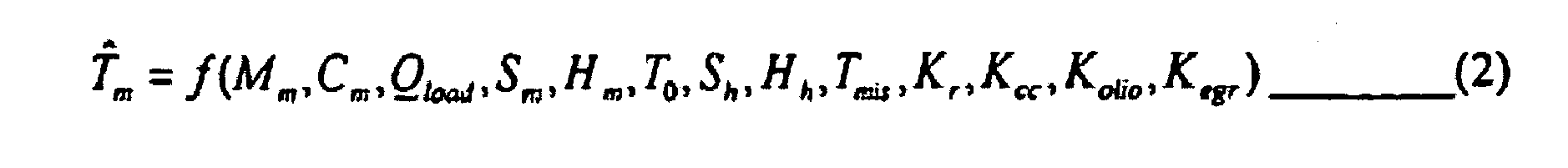 - Mm, welche die Metallmasse darstellt;- Cm, welche die Metall-Wärmekapazität darstellt;- Qload, welche die durch den Motor ausgetauschte Wärmelast darstellt;- Sm, welche die Motorluft-Wärmeaustauschfläche darstellt;- Hm, welche den Motorluft-Wärmeaustauschkoeffizienten darstellt;- Sh, welche die Motorkühlfluid-Wärmeaustauschfläche darstellt;- Hh, welche den Motorkühlfluid-Wärmeaustauschkoeffizienten darstellt;- To, welche die Umgebungstemperatur darstellt;- Tmis, welche die Motorauslass-Kühlfluidtemperatur darstellt;- Kcc, welche ein Parameter ist, durch den die Wärmeleistung zu bestimmen ist, die für die Fahrgastraumklimaanlage erforderlich ist;- Kegr, welche einen Parameter darstellt, durch den die durch den AGR-Wärmeaustauscher ausgetauschte Wärmeleistung zu bestimmen ist;- Koil, welche ein Parameter ist, durch den die durch den Ölaustauscher ausgetauschte Wärmeleistung zu bestimmen ist.
 - Steuersystem nach Anspruch 16, wobei die Gleichung (2) auf einem mathematischen Modell basiert, das die Metalltemperatur an verschiedenen charakteristischen Punkten des Motors bestimmt.
- Steuersystem nach Anspruch 16, wobei die Gleichung (2) auf einer Datenbank basiert, die auf Basis von Prüfmessungen eingelesen wurde.
- Steuersystem nach Anspruch 7, wobei die zweiten Berechnungseinrichtungen (40) umfassen:- eine erste Tabelle, die auf Basis eines empfangenen Wertes des Koeffizienten Kr den Wert Qf des Kühlfluid-Durchflusses bereitstellt, der erforderlich ist, um den erwünschten Temperaturwert Tdes vorzuhalten, wobei die erste Tabelle den Kühlfluid-Durchfluss in einem Zustand berechnet, in dem das dem Kühler zugehörige Gebläse abgeschaltet ist, und- Vergleichseinrichtungen (42) zum Bestimmen, ob der berechnete Kühlfluid-Durchflusswert unter einem gegebenen Grenzwert ist, falls er es ist, wird der unter Verwendung der ersten Tabelle erhaltene Kühlfluid-Durchfluss bezogen und in dem Modell genutzt,- umgekehrt wird eine zweite Tabelle gewählt, die den Wert Qf des Kühlfluid-Durchflusses, der erforderlich ist, um den erwünschten Temperaturwert Tdes vorzuhalten, für den Kühler bereitstellt, wobei die zweite Tabelle den Kühlfluid-Durchfluss in einem Zustand berechnet, in dem das dem Kühler zugehörige Gebläse eingeschaltet ist.
- Steuersystem nach Anspruch 1, wobei das Modell des offenen Regelsystems (15) eine Anzahl von Informationselementen (Inf1), die an dem Motor detektiert werden, empfängt und das Modell auf Basis der Informationselemente aktualisiert.
- Steuersystem nach Anspruch 20, wobei das Modell einen Informationsstrom (Inf2) für einen Kontroller (20) des geschlossenen Regelsystems (14) bereitstellt, um die Steuerparameter des Kontrollers kontinuierlich zu aktualisieren.
Applications Claiming Priority (2)
| Application Number | Priority Date | Filing Date | Title |
|---|---|---|---|
| ITTO20020852 | 2002-10-02 | ||
| IT000852A ITTO20020852A1 (it) | 2002-10-02 | 2002-10-02 | Sistema di controllo per un impianto di raffreddamento del motore di |
Publications (2)
| Publication Number | Publication Date |
|---|---|
| EP1405992A1 EP1405992A1 (de) | 2004-04-07 |
| EP1405992B1 true EP1405992B1 (de) | 2008-01-30 |
Family
ID=31986058
Family Applications (1)
| Application Number | Title | Priority Date | Filing Date |
|---|---|---|---|
| EP03022279A Expired - Lifetime EP1405992B1 (de) | 2002-10-02 | 2003-10-01 | Regelsystem zur Regelung eines Kühlungssystems einer Brennkraftmaschine eines Kraftfahrzeugs |
Country Status (5)
| Country | Link |
|---|---|
| EP (1) | EP1405992B1 (de) |
| AT (1) | ATE385284T1 (de) |
| DE (1) | DE60318926T2 (de) |
| ES (1) | ES2298456T3 (de) |
| IT (1) | ITTO20020852A1 (de) |
Families Citing this family (4)
| Publication number | Priority date | Publication date | Assignee | Title |
|---|---|---|---|---|
| US7409928B2 (en) * | 2006-01-27 | 2008-08-12 | Gm Global Technology Operations, Inc. | Method for designing an engine component temperature estimator |
| DE102009012572B4 (de) * | 2009-03-11 | 2014-01-02 | Audi Ag | Verfahren und Vorrichtung zur Steuerung eines Kühlmittelkreislaufs in einem Kraftfahrzeug |
| DE102009056575B4 (de) * | 2009-12-01 | 2014-01-02 | Continental Automotive Gmbh | Verfahren und Vorrichtung zum Ermitteln eines modellierten Temperaturwertes bei einer Brennkraftmaschine und Verfahren zur Plausibilisierung eines Temperatursensors |
| CN114991934B (zh) * | 2022-06-10 | 2024-02-06 | 上海源悦汽车电子股份有限公司 | 一种发动机冷却液温度控制方法、系统及可读存储模块 |
Family Cites Families (5)
| Publication number | Priority date | Publication date | Assignee | Title |
|---|---|---|---|---|
| JP3044503B2 (ja) * | 1992-02-21 | 2000-05-22 | 本田技研工業株式会社 | エンジンの冷却装置 |
| DE19519377A1 (de) * | 1995-05-26 | 1996-11-28 | Bayerische Motoren Werke Ag | Kühlanlage mit elektrisch regelbarem Stellglied |
| US6321695B1 (en) * | 1999-11-30 | 2001-11-27 | Delphi Technologies, Inc. | Model-based diagnostic method for an engine cooling system |
| DE10123444B4 (de) * | 2001-05-14 | 2006-11-09 | Siemens Ag | Regelanlage zum Regeln der Kühlmitteltemperatur einer Brennkraftmaschine |
| DE10163944A1 (de) * | 2001-12-22 | 2003-07-03 | Bosch Gmbh Robert | Verfahren zur Ansteuerung von elektrisch betätigbaren Komponenten eines Kühlsystems, Computerprogramm, Steuergerät, Kühlsystem und Brennkraftmaschine |
-
2002
- 2002-10-02 IT IT000852A patent/ITTO20020852A1/it unknown
-
2003
- 2003-10-01 AT AT03022279T patent/ATE385284T1/de not_active IP Right Cessation
- 2003-10-01 ES ES03022279T patent/ES2298456T3/es not_active Expired - Lifetime
- 2003-10-01 EP EP03022279A patent/EP1405992B1/de not_active Expired - Lifetime
- 2003-10-01 DE DE60318926T patent/DE60318926T2/de not_active Expired - Lifetime
Also Published As
| Publication number | Publication date |
|---|---|
| ATE385284T1 (de) | 2008-02-15 |
| DE60318926D1 (de) | 2008-03-20 |
| EP1405992A1 (de) | 2004-04-07 |
| ES2298456T3 (es) | 2008-05-16 |
| DE60318926T2 (de) | 2009-01-22 |
| ITTO20020852A1 (it) | 2004-04-03 |
Similar Documents
| Publication | Publication Date | Title |
|---|---|---|
| CN107433845B (zh) | 基于条件的动力系控制系统 | |
| CN109017213B (zh) | 控制通过车辆的加热器芯的冷却液流量的系统及方法 | |
| US20210033097A1 (en) | Method for optimizing the efficiency and/or the running performance of a fan or a fan arrangement | |
| US10401843B2 (en) | Control system with combined extremum-seeking control and feedforward control | |
| Salah et al. | Nonlinear-control strategy for advanced vehicle thermal-management systems | |
| Salah et al. | A smart multiple-loop automotive cooling system—model, control, and experimental study | |
| US10777831B2 (en) | Equation based cooling system control strategy/method | |
| CN114278423B (zh) | 一种基于预测性扩张状态观测器的冷却液温度预测控制方法 | |
| EP3306216A1 (de) | Steuerungsvorrichtung für wärmepumpenverwendendes system und damit ausgestattetes wärmepumpenverwendendes system | |
| US10364997B2 (en) | Control system with maximum time constant estimation | |
| EP0228813A2 (de) | Kraftfahrzeugklimaanlage | |
| CN109296440B (zh) | 使用反馈线性化控制内燃机冷却系统 | |
| CN117053448B (zh) | 一种液冷机组的冷却液温度控制方法、装置以及设备 | |
| CN111636959B (zh) | 控制内燃机的电动冷却剂阀的方法 | |
| Wang et al. | Advanced engine cooling system subjected to ram air effect—nonlinear adaptive multiple input and multiple output (NAMIMO) control | |
| CN111670352B (zh) | 用于在试验台上调节驱动单元的冷却剂回路的冷却剂的温度的方法 | |
| EP1405992B1 (de) | Regelsystem zur Regelung eines Kühlungssystems einer Brennkraftmaschine eines Kraftfahrzeugs | |
| US20060162351A1 (en) | Vehicle air-conditioning unit with an electronic control device | |
| CN120100569A (zh) | 车辆水泵的控制方法、装置、设备、介质及车辆 | |
| Butt et al. | Robust nonlinear control of an innovative engine cooling system | |
| US7660660B2 (en) | Systems and methods for regulation of engine variables | |
| FR2824788A1 (fr) | Dispositif de commande d'un climatiseur automatique d'habitacle de vehicule | |
| CN120096271A (zh) | 车辆集成阀的控制方法、装置、设备、介质及车辆 | |
| US20250264237A1 (en) | Reinforcement Learning Control for High Dimensional Systems Modeled by Partial Differential Equations | |
| Reuscher et al. | Practical Application of Model Predictive Zonal Temperature Estimation and Control for Vehicle Cabins |
Legal Events
| Date | Code | Title | Description |
|---|---|---|---|
| PUAI | Public reference made under article 153(3) epc to a published international application that has entered the european phase |
Free format text: ORIGINAL CODE: 0009012 |
|
| AK | Designated contracting states |
Kind code of ref document: A1 Designated state(s): AT BE BG CH CY CZ DE DK EE ES FI FR GB GR HU IE IT LI LU MC NL PT RO SE SI SK TR |
|
| AX | Request for extension of the european patent |
Extension state: AL LT LV MK |
|
| 17P | Request for examination filed |
Effective date: 20041005 |
|
| AKX | Designation fees paid |
Designated state(s): AT DE ES FR GB |
|
| GRAP | Despatch of communication of intention to grant a patent |
Free format text: ORIGINAL CODE: EPIDOSNIGR1 |
|
| GRAS | Grant fee paid |
Free format text: ORIGINAL CODE: EPIDOSNIGR3 |
|
| GRAA | (expected) grant |
Free format text: ORIGINAL CODE: 0009210 |
|
| AK | Designated contracting states |
Kind code of ref document: B1 Designated state(s): AT DE ES FR GB |
|
| REG | Reference to a national code |
Ref country code: GB Ref legal event code: FG4D |
|
| REF | Corresponds to: |
Ref document number: 60318926 Country of ref document: DE Date of ref document: 20080320 Kind code of ref document: P |
|
| REG | Reference to a national code |
Ref country code: ES Ref legal event code: FG2A Ref document number: 2298456 Country of ref document: ES Kind code of ref document: T3 |
|
| ET | Fr: translation filed | ||
| PLBE | No opposition filed within time limit |
Free format text: ORIGINAL CODE: 0009261 |
|
| STAA | Information on the status of an ep patent application or granted ep patent |
Free format text: STATUS: NO OPPOSITION FILED WITHIN TIME LIMIT |
|
| 26N | No opposition filed |
Effective date: 20081031 |
|
| PGFP | Annual fee paid to national office [announced via postgrant information from national office to epo] |
Ref country code: AT Payment date: 20081024 Year of fee payment: 6 Ref country code: ES Payment date: 20081023 Year of fee payment: 6 |
|
| PGFP | Annual fee paid to national office [announced via postgrant information from national office to epo] |
Ref country code: GB Payment date: 20081022 Year of fee payment: 6 |
|
| PG25 | Lapsed in a contracting state [announced via postgrant information from national office to epo] |
Ref country code: AT Free format text: LAPSE BECAUSE OF NON-PAYMENT OF DUE FEES Effective date: 20091001 |
|
| PG25 | Lapsed in a contracting state [announced via postgrant information from national office to epo] |
Ref country code: GB Free format text: LAPSE BECAUSE OF NON-PAYMENT OF DUE FEES Effective date: 20091001 |
|
| REG | Reference to a national code |
Ref country code: ES Ref legal event code: FD2A Effective date: 20110302 |
|
| PG25 | Lapsed in a contracting state [announced via postgrant information from national office to epo] |
Ref country code: ES Free format text: LAPSE BECAUSE OF NON-PAYMENT OF DUE FEES Effective date: 20110301 |
|
| PG25 | Lapsed in a contracting state [announced via postgrant information from national office to epo] |
Ref country code: ES Free format text: LAPSE BECAUSE OF NON-PAYMENT OF DUE FEES Effective date: 20091002 |
|
| REG | Reference to a national code |
Ref country code: FR Ref legal event code: PLFP Year of fee payment: 14 |
|
| REG | Reference to a national code |
Ref country code: FR Ref legal event code: PLFP Year of fee payment: 15 |
|
| REG | Reference to a national code |
Ref country code: FR Ref legal event code: PLFP Year of fee payment: 16 |
|
| PGFP | Annual fee paid to national office [announced via postgrant information from national office to epo] |
Ref country code: FR Payment date: 20220921 Year of fee payment: 20 |
|
| PGFP | Annual fee paid to national office [announced via postgrant information from national office to epo] |
Ref country code: DE Payment date: 20220920 Year of fee payment: 20 |
|
| REG | Reference to a national code |
Ref country code: DE Ref legal event code: R071 Ref document number: 60318926 Country of ref document: DE |