EP1405891A1 - Photochromic material and color dose meter using the same - Google Patents
Photochromic material and color dose meter using the same Download PDFInfo
- Publication number
- EP1405891A1 EP1405891A1 EP02736111A EP02736111A EP1405891A1 EP 1405891 A1 EP1405891 A1 EP 1405891A1 EP 02736111 A EP02736111 A EP 02736111A EP 02736111 A EP02736111 A EP 02736111A EP 1405891 A1 EP1405891 A1 EP 1405891A1
- Authority
- EP
- European Patent Office
- Prior art keywords
- group
- substituted
- illuminant
- groups
- photochromic material
- Prior art date
- Legal status (The legal status is an assumption and is not a legal conclusion. Google has not performed a legal analysis and makes no representation as to the accuracy of the status listed.)
- Granted
Links
- 0 Cc1c[n](*)cn1 Chemical compound Cc1c[n](*)cn1 0.000 description 5
- ICGIVLUIZPDEJO-UHFFFAOYSA-N Cc1c(C(C(C(C2(F)F)(F)F)(F)F)=C2c2c(C)[s]c3cc(C#N)ccc23)c(ccc(C#N)c2)c2[s]1 Chemical compound Cc1c(C(C(C(C2(F)F)(F)F)(F)F)=C2c2c(C)[s]c3cc(C#N)ccc23)c(ccc(C#N)c2)c2[s]1 ICGIVLUIZPDEJO-UHFFFAOYSA-N 0.000 description 1
- XNTMZSKKYSRQKK-UHFFFAOYSA-N Cc1c(C(C(C(C2(F)[I]=C)(F)[I]=C)(F)[FH+])=C2c2c(C)[s]c3ccccc23)c2ccccc2[s]1 Chemical compound Cc1c(C(C(C(C2(F)[I]=C)(F)[I]=C)(F)[FH+])=C2c2c(C)[s]c3ccccc23)c2ccccc2[s]1 XNTMZSKKYSRQKK-UHFFFAOYSA-N 0.000 description 1
- QMHIMXFNBOYPND-UHFFFAOYSA-N Cc1c[s]cn1 Chemical compound Cc1c[s]cn1 QMHIMXFNBOYPND-UHFFFAOYSA-N 0.000 description 1
Images


Classifications
-
- G—PHYSICS
- G01—MEASURING; TESTING
- G01T—MEASUREMENT OF NUCLEAR OR X-RADIATION
- G01T1/00—Measuring X-radiation, gamma radiation, corpuscular radiation, or cosmic radiation
- G01T1/02—Dosimeters
- G01T1/04—Chemical dosimeters
-
- C—CHEMISTRY; METALLURGY
- C09—DYES; PAINTS; POLISHES; NATURAL RESINS; ADHESIVES; COMPOSITIONS NOT OTHERWISE PROVIDED FOR; APPLICATIONS OF MATERIALS NOT OTHERWISE PROVIDED FOR
- C09K—MATERIALS FOR MISCELLANEOUS APPLICATIONS, NOT PROVIDED FOR ELSEWHERE
- C09K9/00—Tenebrescent materials, i.e. materials for which the range of wavelengths for energy absorption is changed as a result of excitation by some form of energy
- C09K9/02—Organic tenebrescent materials
-
- C—CHEMISTRY; METALLURGY
- C09—DYES; PAINTS; POLISHES; NATURAL RESINS; ADHESIVES; COMPOSITIONS NOT OTHERWISE PROVIDED FOR; APPLICATIONS OF MATERIALS NOT OTHERWISE PROVIDED FOR
- C09K—MATERIALS FOR MISCELLANEOUS APPLICATIONS, NOT PROVIDED FOR ELSEWHERE
- C09K2211/00—Chemical nature of organic luminescent or tenebrescent compounds
- C09K2211/10—Non-macromolecular compounds
- C09K2211/1018—Heterocyclic compounds
- C09K2211/1025—Heterocyclic compounds characterised by ligands
- C09K2211/1029—Heterocyclic compounds characterised by ligands containing one nitrogen atom as the heteroatom
-
- C—CHEMISTRY; METALLURGY
- C09—DYES; PAINTS; POLISHES; NATURAL RESINS; ADHESIVES; COMPOSITIONS NOT OTHERWISE PROVIDED FOR; APPLICATIONS OF MATERIALS NOT OTHERWISE PROVIDED FOR
- C09K—MATERIALS FOR MISCELLANEOUS APPLICATIONS, NOT PROVIDED FOR ELSEWHERE
- C09K2211/00—Chemical nature of organic luminescent or tenebrescent compounds
- C09K2211/10—Non-macromolecular compounds
- C09K2211/1018—Heterocyclic compounds
- C09K2211/1025—Heterocyclic compounds characterised by ligands
- C09K2211/1029—Heterocyclic compounds characterised by ligands containing one nitrogen atom as the heteroatom
- C09K2211/1037—Heterocyclic compounds characterised by ligands containing one nitrogen atom as the heteroatom with sulfur
-
- C—CHEMISTRY; METALLURGY
- C09—DYES; PAINTS; POLISHES; NATURAL RESINS; ADHESIVES; COMPOSITIONS NOT OTHERWISE PROVIDED FOR; APPLICATIONS OF MATERIALS NOT OTHERWISE PROVIDED FOR
- C09K—MATERIALS FOR MISCELLANEOUS APPLICATIONS, NOT PROVIDED FOR ELSEWHERE
- C09K2211/00—Chemical nature of organic luminescent or tenebrescent compounds
- C09K2211/10—Non-macromolecular compounds
- C09K2211/1018—Heterocyclic compounds
- C09K2211/1025—Heterocyclic compounds characterised by ligands
- C09K2211/1092—Heterocyclic compounds characterised by ligands containing sulfur as the only heteroatom
-
- C—CHEMISTRY; METALLURGY
- C09—DYES; PAINTS; POLISHES; NATURAL RESINS; ADHESIVES; COMPOSITIONS NOT OTHERWISE PROVIDED FOR; APPLICATIONS OF MATERIALS NOT OTHERWISE PROVIDED FOR
- C09K—MATERIALS FOR MISCELLANEOUS APPLICATIONS, NOT PROVIDED FOR ELSEWHERE
- C09K2211/00—Chemical nature of organic luminescent or tenebrescent compounds
- C09K2211/10—Non-macromolecular compounds
- C09K2211/1018—Heterocyclic compounds
- C09K2211/1025—Heterocyclic compounds characterised by ligands
- C09K2211/1096—Heterocyclic compounds characterised by ligands containing other heteroatoms
Definitions
- the present invention relates to a photochromic material useful for measuring a radiation dose and a color dose meter employing it, whereby a radiation dose can simply be measured.
- Irradiation treatment by means of X-rays, ⁇ -rays, etc. has been common for the purpose of sterilization of medical equipments.
- such treatment is applied also to blood for transfusion to prevent a graft-versus-host disease (GVHD) by blood transfusion.
- GVHD graft-versus-host disease
- an oxidation-reduction dye such as a leuco dye and a polyvinyl chloride
- This indicator undergoes a color change when irradiated with a radiation of at least 5000 Gy.
- the irradiation dose to blood for transfusion is usually at a level of from 15 to 50 Gy, and therefore, the presence or absence of such irradiation can not be detected by this indicator.
- JP-A-2-201440 discloses, as an indicator which undergoes a color change when irradiated with a radiation of from 15 to 50 Gy, a radiation color-changeable composition having a metal such as calcium doped on an alkali metal halide such as potassium chloride.
- a metal such as calcium doped on an alkali metal halide such as potassium chloride.
- a halide of an alkali metal is weak to moisture and has been disadvantageous for use in a medical field where it is often in contact with moisture.
- JP-A-2000-65934 discloses a dose meter comprising an organic compound showing an electron accepting property by a radiation and a color-forming electron releasing organic compound.
- the disclosed electron releasing organic compound is generally known to be susceptible to the influence of moisture or impurities in air, and there has been a drawback that the dose meter employing it is poor in the storage stability. Further, such an indicator can not be decolored and in many cases can not be re-used.
- JP-A-2-216493 discloses a radiation-sensitive display sheet made of a laminate having a layer containing a scintillator which emits fluorescence and a layer containing a diarylethene compound which undergoes a color change in response to the fluorescence emitted by this scintillator.
- a maleic anhydride type diarylethene compound such as 2,4,5-trimethylthienylmaleic anhydride used in this reference is inadequate in the sensitivity to a radiation.
- the maleic anhydride moiety undergoes hydrolysis by moisture, and there has been a drawback that the storage stability is poor.
- JP-A-11-258348 discloses a dose meter employing a heat irreversible diarylethene compound.
- a radiation having a relatively low dose can accurately be measured.
- diarylethene compound(s) (a photochromic compound(s)) having a certain specific structure and an illuminant(s) which emits a light when irradiated with a radiation.
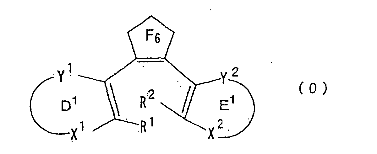
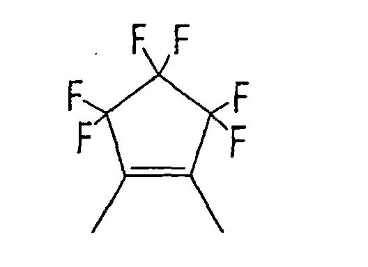
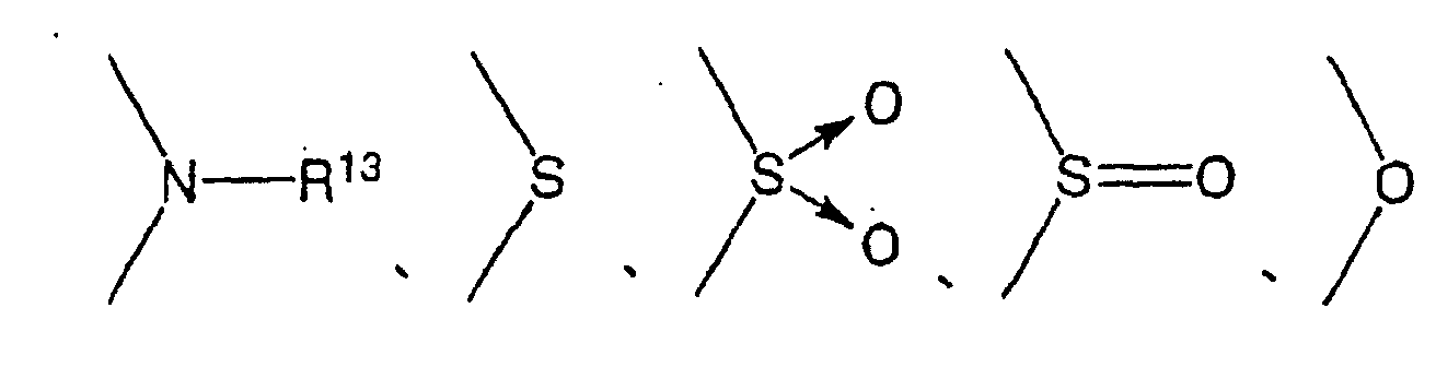
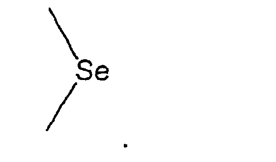
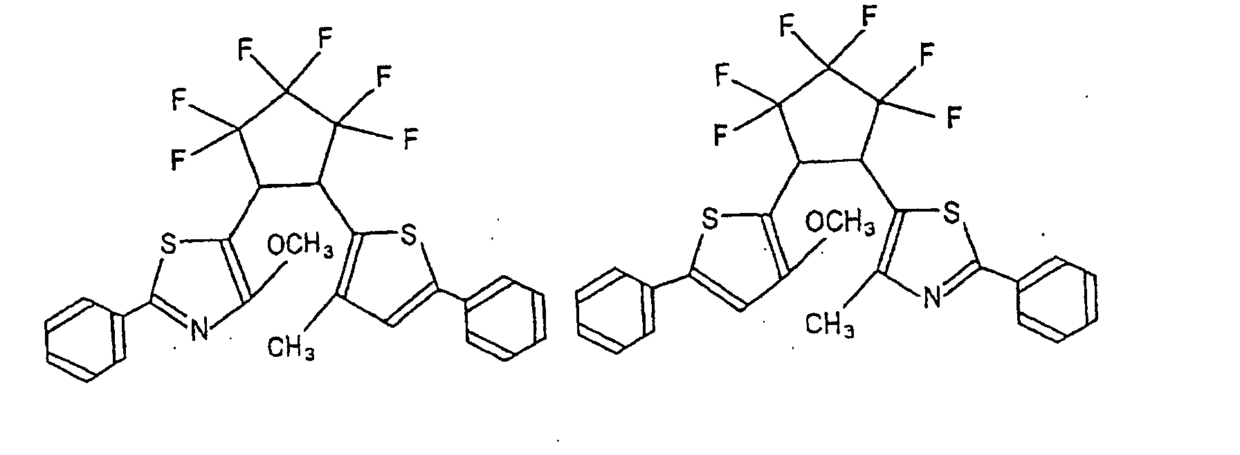
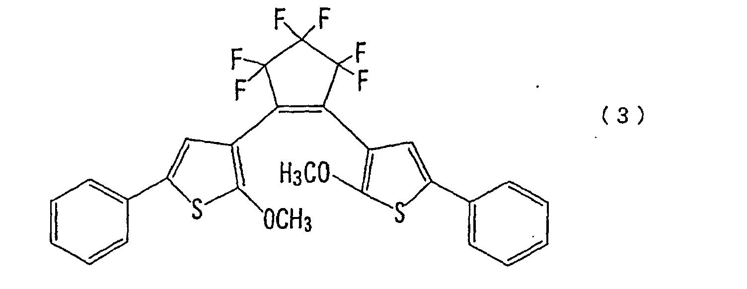
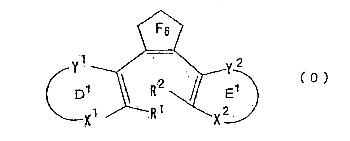
- the gist of the present invention resides in a photochromic material comprising an illuminant(s) which emits a light when irradiated with a radiation, and a diarylethene compound(s), wherein the diarylethene compound(s) is represented by the following formula (0), and the absorption spectrum of the ring opened form or the ring closed form of the diarylethene compound(s), and the emission spectrum of the illuminant(s), overlap each other: in the above formula (0), each of groups R 1 and R 2 which are independent of each other, is an alkyl group, a cycloalkyl group or an alkoxy group, each of groups X 1 , X 2 , Y 1 and Y 2 which are independent of one another, is either one of and group R 3 is a hydrogen atom, an alkyl group which may be substituted, an aryl group which may be substituted, or a cycloalkyl group which may be substituted, group R 4 is a
- Another gist of the present invention resides in a color dose meter prepared by using such a photochromic material.
- the diarylethene compound(s) means a compound(s) which undergoes an isomerization reaction when irradiated with a light or radiation.
- the diarylethene compound(s) to be used in the present invention is a compound(s) represented by the above formula (0).
- substituents which rings D and E in the formula (0) may have are not particularly limited, but may preferably be various groups which will be described hereinafter as groups R 13 , R 15 to R 17 , R 23 , and R 25 to R 27 .
- such a condensed ring may have substituents such as an alkenyl group, an alkoxy group, an alkoxyalkoxy group, an allyloxy group, an aryl group, an aryloxy group, a heteroaryl group, a halogen atom, a hydroxyl group, a carboxyl group, a carbonyl group, a cyano group and a nitro group.
- the compound represented by the above formula (0) may, preferably, be a compound represented by the following formula (I) or (II):
- each of groups R 11 and R 12 which are independent of each other is an alkyl group, a cycloalkyl group or an alkoxy group.
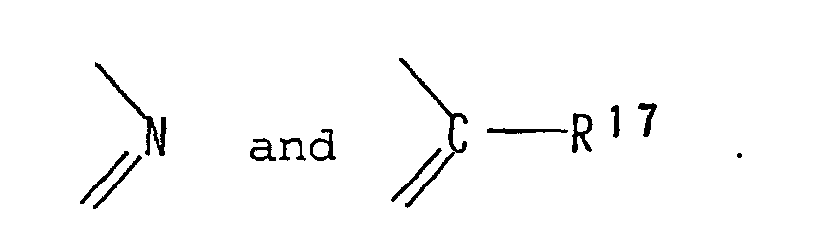
- each of groups X 11 and X 12 which are independent of each other, is either one of and but among them, preferred are and
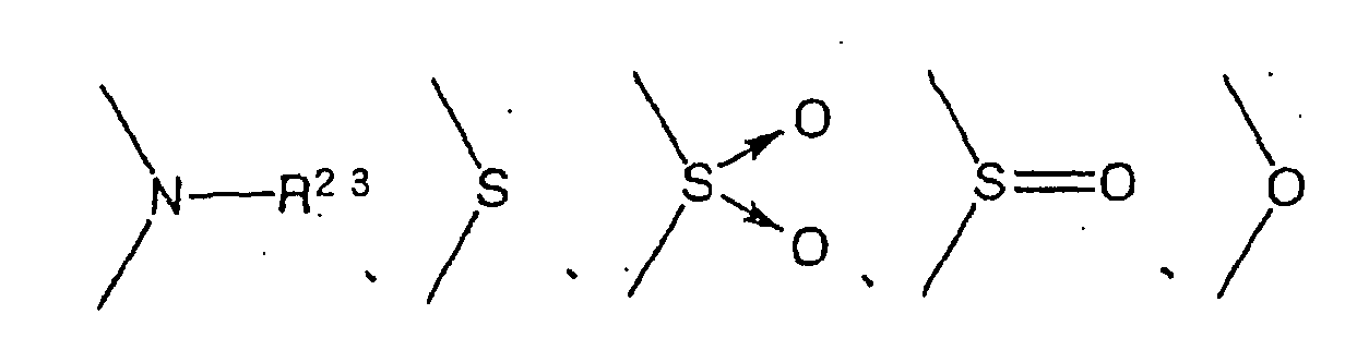
- each of groups Y 11 and Y 12 which are independent of each other, is either one of
- group R 13 is a hydrogen atom, an alkyl group which may be substituted, an aryl group which may be substituted, or a cycloalkyl group which may be substituted, but among them, a hydrogen atom, an alkyl group which may be substituted, or an aryl group which may be substituted, is preferred.
- group R 17 is independently a hydrogen atom, an alkyl group which may be substituted, or a cycloalkyl group which may be substituted.
- Each of groups R 15 and R 16 which are independent of each other, is a hydrogen atom, an alkyl group which may be substituted, an aryl group which may be substituted, a heteroaryl group which may be substituted, or a cycloalkyl group which may be substituted.
- R 15 and R 16 are an alkyl group, an aryl group, a heteroaryl group or a cycloalkyl group
- substituents which these groups may have may, for example, be an alkenyl group, an alkoxy group, an alkoxyalkoxy group, an allyloxy group, an aryl group, a heteroaryl group, an aryloxy group, a halogen atom, a hydroxyl group, a carboxyl group, a carbonyl group, a cyano group and a nitro group.
- group Y 11 and/or group Y 12 is group R 15 and/or group R 16 may be bonded to group R 17 to form a 5- or 6-membered aromatic ring.
- Substituents which such an aromatic ring may have may, for example, be an alkenyl group, an alkoxy group, an alkoxyalkoxy group, an allyloxy group, an aryl group, a heteroaryl group, an aryloxy group, a halogen atom, a hydroxyl group, a carboxyl group, a carbonyl group, a cyano group and a nitro group.
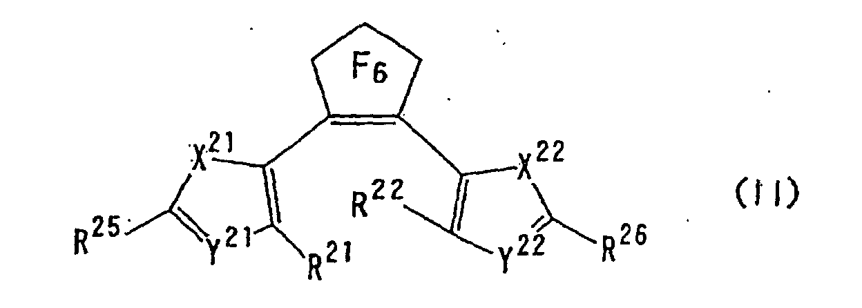
- each of groups R 21 and R 22 which are independent of each other is an alkyl group, a cycloalkyl group or an alkoxy group.
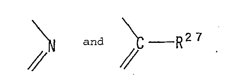
- each of groups X 23 and X 24 which are independent of each other, is either one of and
- each of groups Y 21 and Y 22 is either one of
- each of groups R 25 and R 26 which are independent of each other is a hydrogen atom, an alkyl group which may be substituted, an aryl group which may be substituted, a heteroaryl group which may be substituted, or a cycloalkyl group which may be substituted.
- group Y 21 and/or group Y 22 is group R 25 and/or group R 26 may be bonded to R 27 to form a 5- or 6-membered aromatic ring.
- Substituents which the aromatic ring may have may, for example, be an alkenyl group, an alkoxy group, an alkoxyalkoxy group, an allyloxy group, an aryl group, a heteroaryl group, an aryloxy group, a halogen atom, a hydroxyl group, a carboxyl group, a carbonyl group, a cyano group and a nitro group.
- group R 23 is a hydrogen atom, an alkyl group which may be substituted, an aryl group which may be substituted, or a cycloalkyl group which may be substituted, but, among them, a hydrogen atom, an alkyl group which may be substituted, or an aryl group which may be substituted, is preferred.
- group R 27 is a hydrogen atom, an alkyl group which may be substituted, or a cycloalkyl group which may be substituted.
- substituents which these groups may have may, for example, be an alkenyl group, an alkoxy group, an alkoxyalkoxy group, an allyloxy group, an aryl group, a heteroaryl group, an aryloxy group, a halogen atom, a hydroxyl group, a carboxyl group, a carbonyl group, a cyano group and a nitro group.
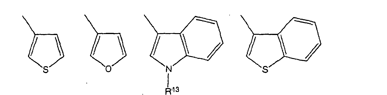
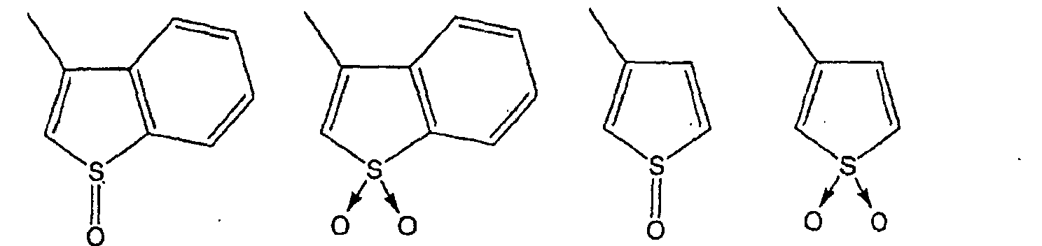
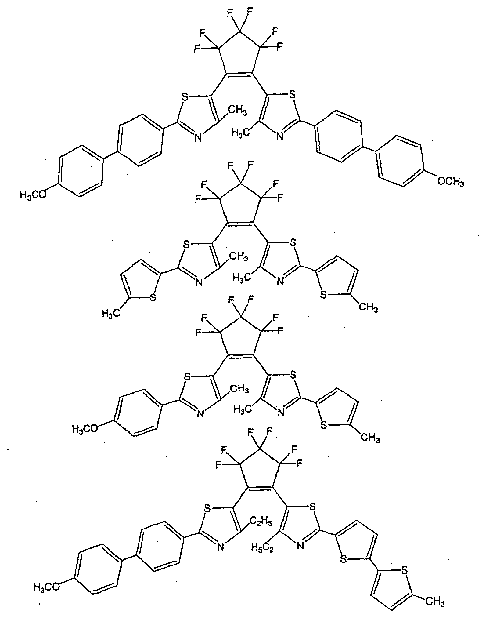
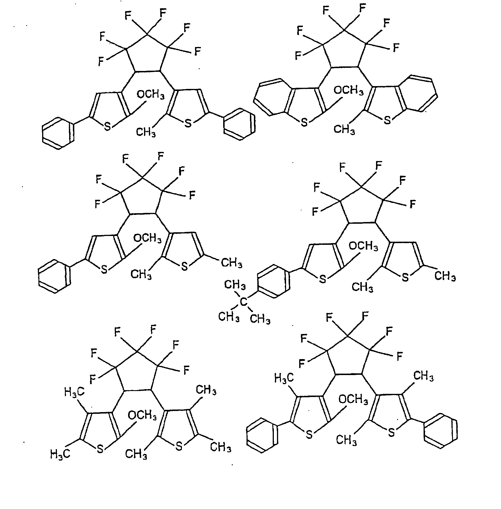
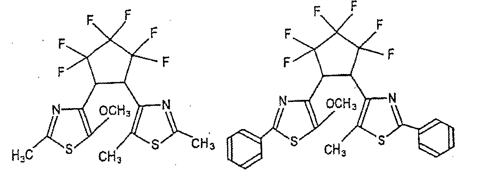
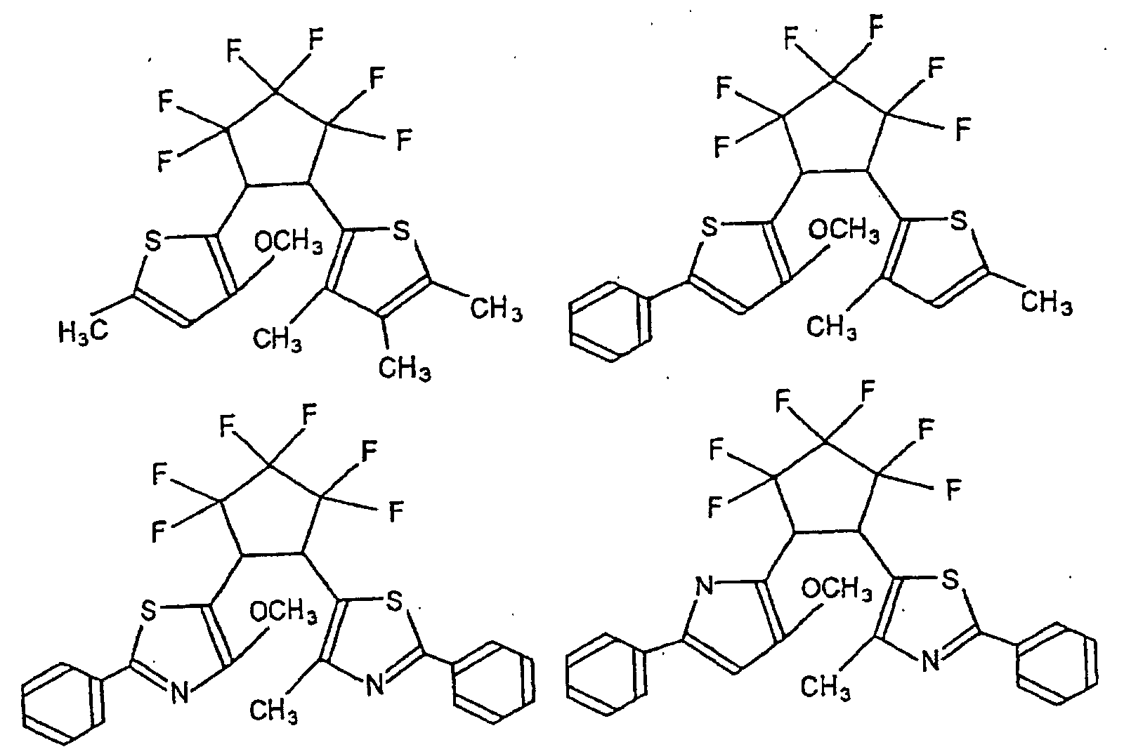
- rings D 1 and E 1 in the formula (I) will be shown below, but they are not limited to such specific examples.
- R 13 is as defined in the above formula (I), and R 27 is as defined in the above formula (II).
- hetero ring containing groups X 11 and Y 11 are preferred as the hetero ring containing groups X 11 and Y 11 , and as the hetero ring containing groups X12 and Y 12 :
- the benzene ring condensed to a hetero ring is a ring formed by the bonding of group R 15 or R 16 to group R 17 .
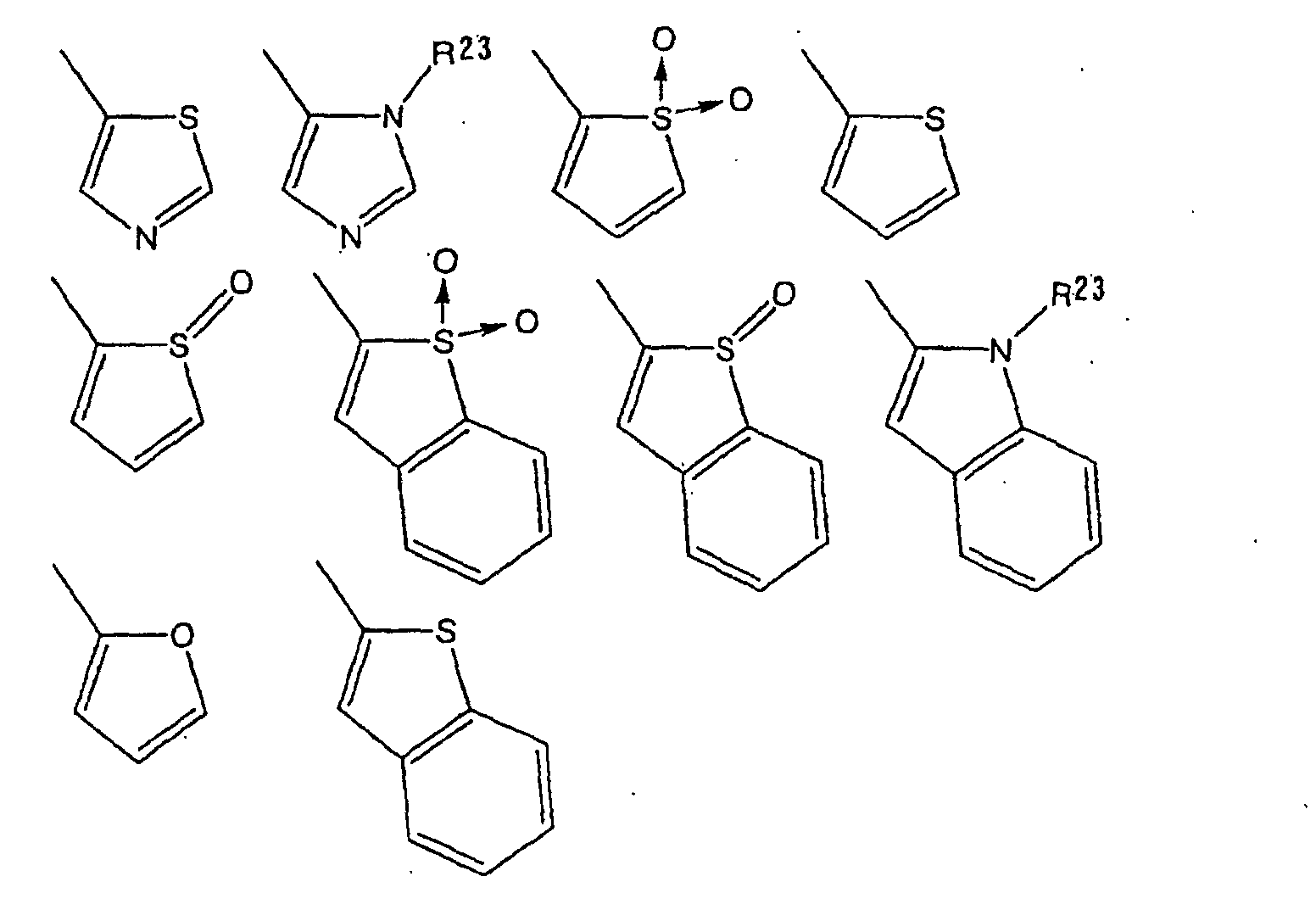
- hetero ring containing groups X 21 and Y 21 or the hetero ring containing groups X 22 and Y 22 , in the above formula (II), are the following ones:
- the benzene ring condensed to a hetero ring is a ring formed by the bonding of group R 25 or R 26 to group R 27 .
- diarylethene compounds shown above can be produced optionally by means of conventional techniques.
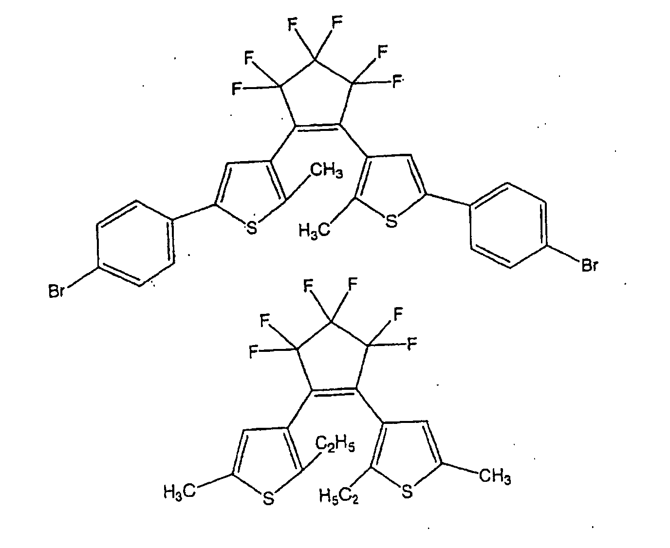
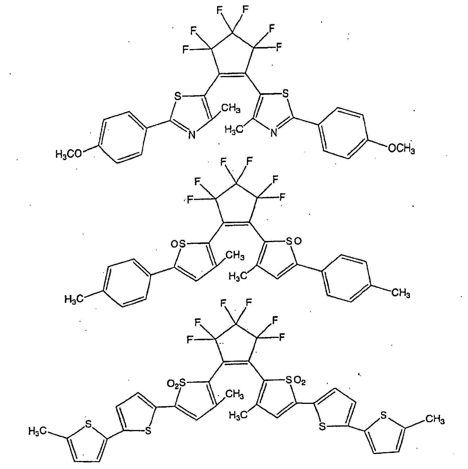
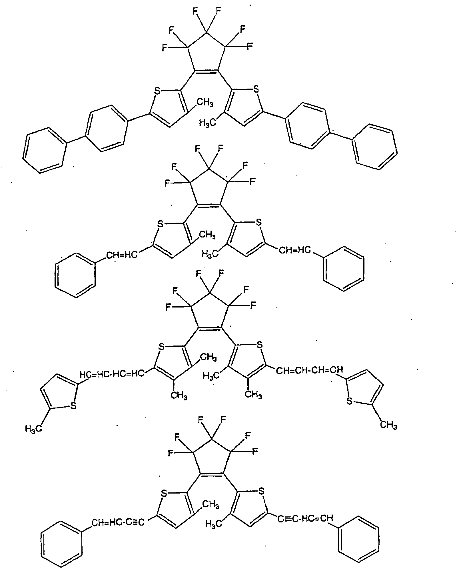
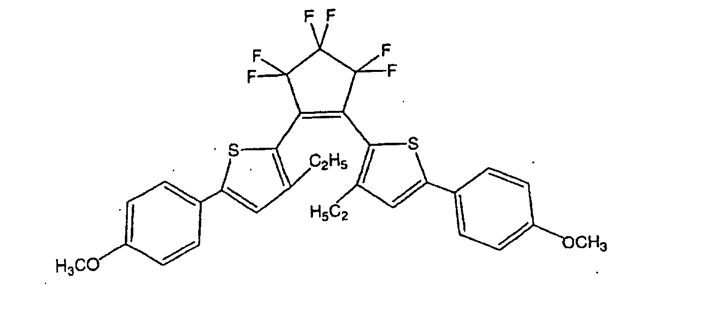
- they can be prepared by techniques optionally selected from those disclosed in e.g. JP-A-9-241625.
- diarylethene compounds may be used alone or may be used in combination as a mixture of a plurality of them.
- a plurality of them may be selected from a group of compounds represented by either one of the above formulae (I) and (II), or at least one type may be selected for use from the respective groups of compounds represented by the above formulae (I) and (II).
- an optional compound other than the group of compounds represented by the above formula (I) or (II) may be used in combination.
- the diarylethene compound(s) to be used in the present invention is preferably one showing a heat irreversibility.
- heat irreversibility means that the half-life time of the ring closed form in an environment of 30°C is at least 10 days.
- the diarylethene compound is not heat irreversible, it is likely that the ring closed form readily undergoes an isomerization reaction at room temperature and becomes to be a ring opened form, whereby the state of the color change formed by the irradiation of a radiation can not be stably maintained.
- the quantum yield in the ring opening reaction is preferably at most 10 -3 , more preferably at most 10 -4 , particularly preferably at most 10 -5 .
- the illuminant(s) to be used in the present invention is not particularly limited with respect to its type, so long as it can be excited to emit a light when irradiated with a radiation.
- the type of the radiation is not particularly limited, and various types such as ultraviolet rays, X-rays, ⁇ -rays, ⁇ -rays, ⁇ -rays, electron rays and neutron rays may, for example, be mentioned.
- the illuminant(s) to be used in the present invention is preferably one which can be excited to emit a light by a radiation having a wavelength of from about 10 -5 to 10 nm.
- an illuminant(s) comprising atoms usually having an atomic mass larger than a diarylethene compound(s), is used in combination, whereby it is possible to efficiently capture a radiation. Further, by the energy transfer or the electron transfer from the illuminant(s) in an excited state, the isomerization reaction of the diarylethene compound(s) is accelerated, whereby the sensitivity to a radiation of the photochromic material will be improved (a sensitizing effect).
- the type of the light emitted from the illuminant(s) is not particularly limited. However, as described hereinafter, it is required to have an emission spectrum which overlaps an absorption spectrum of the ring opened form or the ring closed form of the diarylethene compound(s).
- Fig. 3 the overlapping of the emission spectrum of the illuminant(s) and the absorption spectrum of the diarylethene compound(s), is shown schematically.
- a phosphor an ultraviolet light emitting phosphor having an emission peak in the ultraviolet wavelength region, i.e. a phosphor which is considered to have an excitation energy level higher than the diarylethene compound.
- a phosphor an ultraviolet light emitting phosphor
- Particularly preferred is one which emits a light within the ultraviolet wavelength region with a wavelength of from 10 to 400 nm.
- the illuminant(s) in the present invention is preferably an inorganic compound.
- the illuminant(s) is preferably one having a high sensitivity to a radiation and has a sufficiently large quantity of emission.
- an illuminant comprising so-called heavy atoms, since atoms having large atomic numbers (heavy atoms) usually have high sensitivity to a radiation.
- an illuminant comprising elements having atomic numbers of at least 19, is preferred, and especially, an illuminant comprising elements having atomic numbers of at least 37, is more preferred.
- illuminant(s) to be used in the present invention various illuminants used as practical phosphors may be mentioned, including, for example, a halophosphate phosphor such as 3Ca 3 (PO 4 ) 2 •Ca(F, Cl) 2 :Sb 3+ , 3Ca 3 (PO 4 ) 2 •Ca(F, Cl) 2 :Sb 3+ , Mn 2+ , Sr 10 (PO 4 ) 6 Cl 2 :Eu 2+ , (Sr, Ca) 10 (PO 4 ) 6 Cl 2 :Eu 2+ , (Sr, Ca) 10 (PO 4 ) 6 Cl 2 •nB 2 O 3 :Eu 2+ , (Ba, Ca, Mg) 10 (PO 4 ) 6 Cl 2 :EU 2+ , a phosphate phosphor such as Sr 2 P 2 O 7 :S n 2+ , Ba 2 P 2 O 7 :Ti 4+ , (Sr
- illuminants can be optionally prepared by means of known techniques. Most of these illuminants contain the above-mentioned elements having atomic numbers of at least 19 or elements having atomic numbers of at least 37, whereby the sensitivity to a radiation is high, and the quantity of emission is sufficiently large.
- ultraviolet-emitting phosphors such as Ca 3 (PO 4 ) 2 :Tl + , (Ca, Zn) 3 (PO 4 ) 2 :Tl + , SrMgP 2 O 7 :Eu 2+ , SrB 4 O 7 F:Eu 2+ , (Ba, Sr, Mg) 3 Si 2 O 7 :Pb 2+ , (Ba, Mg, Zn) 3 Si 2 O 7 :Pb 2+ , BaSi 2 O 5 :Pb 2+ , (Sr, Ba)Al 2 Si 2 O 8 :Eu 2+ , CeMgAl 11 O 19 , (Ce, Gd) (Mg, Ba)Al 11 O 19 , SrB 4 O 7 :Eu 2+ , CsF, BaF 2 , BaSO 4 :Eu 2+ , BaFCl:Eu 2+ , BaFBr:Eu 2+ , HfP 2 O 7
- the illuminant(s) to be used in the present invention one having high luminous efficiency to irradiated light is preferred. Namely, for example, in a case where the photochromic material of the present invention is used for a color dose meter which will be described hereinafter, the illuminant(s) is preferably one having high luminous efficiency to stimulation by a light having a wavelength to be detected.
- the illuminants represented by the above-mentioned various phosphors may be used alone or in combination as a mixture of a plurality of them.
- the photochromic material of the present invention is characterized in that the diarylethene compound(s) and the illuminant(s) are selected for combination so that part or whole of the emission spectrum of the illuminant(s) will overlap the absorption spectrum of the ring opened form or the ring closed form of the diarylethene compound(s).
- the photochromic material of the present invention is used for a color dose meter, firstly, by irradiation of a radiation, electrons of the illuminant(s) will be in an excited state, and the energy or electrons will transfer from such an excited state to an excited state of the diarylethene compound(s), whereby an isomerization reaction of the diarylethene compound(s) will take place.
- the photochromic material undergoes a color change, whereby the irradiated radiation can efficiently be detected, and it will be possible to measure the dose with high sensitivity.
- the diarylethene compound(s) For example in the case of the diarylethene compound(s), a light within an ultraviolet wavelength region with a wavelength of from 10 to 400 nm is preferred in order to let the isomerization reaction from the open ring form take place efficiently. Accordingly, as the illuminant(s) in the present invention, one having the emission peak mainly in this ultraviolet wavelength region (i.e. the above-mentioned ultraviolet-emitting phosphor) is preferred. It is preferred that the emission spectrum of the illuminant(s) and the absorption band containing the maximum absorption wavelength of the ring opened form or the ring closed form of the diarylethene compound(s), overlap each other over a wavelength range as wide as possible.
- the emission spectrum of the illuminant(s) overlaps the absorption spectrum of the ring opened form of the diarylethene compound(s), because the ring opened form usually has an absorption in the wavelength region of the radiation, the quantum yield is higher in the ring closing reaction than in the ring-opening reaction in many cases, and the ring closed form has a deep visible color than the ring opened form in many cases, whereby it is easier to detect the exposure by the formation of the ring closed form.
- illuminants may be used alone or in combination as a mixture of two or more of them.
- the absorption spectrum peak of the diarylethene compound is sharp, if the same illuminant is used, a strong emission can be obtained at a specific wavelength range, and the sensitivity in detection of the radiation can be increased.
- the absorption spectrum peak of the diarylethene compound is broad, if two or more illuminants showing emissions at different wavelength ranges, are used in combination, an emission can be obtained within a wide wavelength range, whereby a radiation within a wide wavelength range can efficiently be detected.
- the photochromic material of the present invention is not particularly limited so long as it is in a mode wherein the above-mentioned diarylethene compound(s) and the illuminant(s) act on each other mutually. However, it is particularly preferred to constitute it as a composition comprising the above-mentioned diarylethene compound(s) and the illuminant(s) or as a laminate comprising a layer containing the above-mentioned diarylethene compound(s) and a layer containing the illuminant(s).
- the former composition is broadly meant for a solid and a liquid, in which the above-mentioned diarylethene compound(s) and the illuminant(s) are contained in a mixed state.
- a solution or dispersion of the diarylethene compound(s) prepared by dissolving or dispersing the above diarylethene compound(s) and dispersing also the illuminant(s), a resin composition containing the above-mentioned diarylethene compound(s) and the illuminant(s), or a molded product prepared by mixing the diarylethene compound(s) and the illuminant(s) in solid states may, for example, be mentioned.
- the photochromic materials of the present invention constructed in the above respective embodiments can be used as color dose meters, respectively, in such manners as depending on the respective embodiments.
- a solution or dispersion of the diarylethene compound(s) as an embodiment of the photochromic material of the present invention can be prepared by dissolving or dispersing the above-mentioned diarylethene compound(s) in a solvent or in a dispersing medium and at the same time, dispersing the above-mentioned illuminant(s) in the above-mentioned solvent or dispersing medium.
- the solvent (dispersing medium) is not particularly limited so long as it is capable of dissolving or dispersing the above-mentioned diarylethene compound(s) and it does not hinder detection of the color change of the diarylethene compound(s) by exposure to a radiation when used as a color dose meter.
- various organic solvents may be mentioned, including an aromatic solvent such as benzene or toluene, an aliphatic solvent such as hexane, an ether solvent such as tetrahydrofuran (THF), and a chlorine type solvent such as chloroform.
- an aromatic solvent such as benzene or toluene is preferred.
- the above-mentioned diarylethene compound(s) is dissolved or dispersed, and at the same time, the above-mentioned illuminant(s) is dispersed to obtain the solution or dispersion of the diarylethene compound(s).
- the amount of the diarylethene compound(s) is preferably within a range of from 10 -5 to 10 mol/l in the solution or dispersion, and the amount of the illuminant(s) is preferably within a range of from 0.5 to 100 parts by weight per 100 parts by weight of the solution or dispersion.
- a known dispersing agent or the like may further be incorporated.
- the solution or dispersion of the diarylethene compound(s), thus prepared, is sealed in a quartz cell or the like containing no impurities, to obtain a color dose meter.
- the color of the solution or dispersion changes depending upon the dose of the radiation. This absorption, transmission or reflection spectrum is measured, and the change in the absorbance, transmittance or reflectance is determined, whereby the dose of the radiation can be estimated.
- the resin composition as one embodiment of the photochromic material of the present invention can be prepared, for example, (a) by dissolving (dispersing) the above-mentioned diarylethene compound(s) and the illuminant(s) in a solvent (dispersing medium) together with a base resin, or (b) by dissolving (dispersing) the above-mentioned diarylethene compound(s) and the illuminant(s) directly in the base resin.
- the base resin is not particularly limited so long as it is capable of suitably dissolving or dispersing the above-mentioned diarylethene compound(s).
- an acrylic resin, a methacrylic resin, a vinyl acetate resin, a vinyl chloride resin, a polyethylene resin, a polypropylene resin, a polystyrene resin, a polynaphthalene resin, a polycarbonate resin, a polyethylene terephthalate resin or a polyvinyl butyral resin may, for example, be mentioned.
- the solvent (dispersing medium) in the above method (a) is not particularly limited so long as it is capable of suitably dissolving or dispersing the above base resin and it does not hinder the film forming process.
- various organic solvents may be mentioned, including, for example, an aromatic solvent such as benzene or toluene, an aliphatic solvent such as hexane, an ether solvent such as THF, a chlorine type solvent such as chloroform, and a ketone solvent such as methyl ethyl ketone.
- the base resin and the above-mentioned diarylethene compound(s) are dissolved or dispersed, and then, the above-mentioned illuminant(s) is added and dispersed to prepare the resin composition.
- the amount of the diarylethene compound(s) is preferably within a range of from 0.2 to 200 parts by weight per 100 parts by weight of the base resin, and the amount of the illuminant(s) is preferably within a range of from 1 to 2000 parts by weight, more preferably within a range of from 5 to 2000 parts by weight, per 100 parts by weight of the base resin.
- a known dispersant(s), antioxidant(s), oxygen-trapping agent(s), plasticizer(s) or the like may be added.
- the resin composition thus prepared may be formed into a film or a rod by means of a known method such as injection molding, extrusion molding or heat pressing, to obtain a color dose meter.
- a known method such as injection molding, extrusion molding or heat pressing
- the film-forming processing can be carried out by means of various known techniques such as a casting method, a spin coating method, a bar coater method, a die cast method, etc.
- the thickness of the film is not particularly limited so long as it does not depart from the purpose for the color dose meter, but it is preferably within a range of from 0.01 to 10 mm.
- the color will change depending upon the dose of the radiation. This absorption, transmission or reflection spectrum is measured, and the change in the absorbance, transmittance or reflectance is determined, whereby the dose of the radiation can be estimated.
- the molded product as one embodiment of the photochromic material of the present invention can be prepared by mixing the solid diarylethene compound(s) and the solid illuminant(s), and compressing this mixture to mold it into a solid having a specific shape.
- the illuminant powder having the particle size adjusted to a median particle diameter of from about 10 nm to 50 ⁇ m, the above-mentioned diarylethene compound(s) having the particle size adjusted to a median particle diameter of from 10 nm to 100 ⁇ m, and, if necessary, a binder, are thoroughly mixed, and then, the mixed powder is filled in a mold, followed by compression molding under a pressure of from 1 MPa to 1 GPa.
- the median particle diameter of the illuminant(s) is smaller than 10 nm, the powder tends to be agglomerated, whereby there may be a case where no adequate mixing with the diarylethene compound(s) can be made.
- the median particle diameter exceeds 50 ⁇ m there may be a case where it becomes difficult to maintain the shape as a molded product.
- the median particle diameter of the diarylethene compound(s) is usually from about 10 nm to 100 ⁇ m, but it is preferably a particle size whereby the compound(s) can readily penetrate into spaces of the illuminant(s). Accordingly, it is more preferably from about 10 nm to 50 ⁇ m.
- the binder to be used is not particularly limited so long as it is one commonly known as a binder to be used for inorganic powders.
- inorganic binders such as a water-soluble substance such as water glass, a sol substance such as silica sol or alumina sol, and various cements which undergo hydration reactions, but also organic binders such as nitrocellulose, cellulose acetate, ethylcellulose, polyvinyl butyral, a vinyl chloride/vinyl acetate copolymer, a polyalkyl (meth)acrylate, polycarbonate, polyurethane, cellulose acetate butyrate, polyvinyl alcohol, gelatin, a polysaccharide such as dextrin, and gum arabic, may be mentioned.
- one having an optional shape may be used depending upon the shape to be used as a color dose meter.
- the mixed powder is filled in a mold and then compressed by means of a single screw extruder or a twin screw extruder to mold it into a flat plate shape.
- the mixed powder is filled into a rubber mold having a complex shape and then compressed by means of a hydraulic pressing machine to mold it into the complex shape.
- the compression molding pressure is preferably from 1 MPa to 1 GPa. If the pressure is less than 1 MPa, no adequate mechanical strength tends to be imparted, whereby it is likely that the molded product can not maintain its shape. On the other hand, if the pressure is higher than 1 GPa, an installation more than necessary for the molding will be required, whereby an extra cost is likely to be incurred.
- the illuminant powder adjusted to the above-mentioned particle size and, if necessary, the above-mentioned binder, are thoroughly mixed and compression-molded, and then the molded product is fired under the firing conditions suitable for the type of the illuminant.
- the above-mentioned diarylethene compound(s) is coated, or the above-mentioned diarylethene compound(s) is impregnated into the interior of the porous sintered body thus obtained.
- Such coating or impregnation is carried out by dissolving or dispersing the above-mentioned diarylethene compound(s) in a suitable solvent.
- the firing conditions suitable for the type of the illuminant(s) are preferably conditions close to the firing temperature, retention time and atmosphere employed at the time of preparing the illuminant powder.
- a preferred firing temperature range is from 500 to 1900°C, and the retention time is from 10 minutes to 48 hours.
- the atmosphere is optionally adjusted to be e.g. an oxidizing atmosphere, a reducing atmosphere or a sulfiding atmosphere, depending upon the composition of the illuminant(s) and the type of the luminescent ions.
- the molded product thus molded into a desired shape such as a film shape, a rod-shape or a plate shape, can be used as it is, as a color dose meter.
- a desired shape such as a film shape, a rod-shape or a plate shape
- the color of the molded product will change depending upon the dose of the radiation. This absorption, transmission or reflection spectrum is measured, and the change in the absorbance, transmittance or reflectance is determined, whereby the dose of the radiation can be estimated.
- the laminate as one embodiment of the photochromic material of the present invention comprises at least a layer containing the above-mentioned diarylethene compound(s) and a layer containing the illuminant(s).
- FIG. 1 is a cross-sectional view schematically illustrating an example of the layered structure of a laminate.
- a luminescent layer 2 containing the above-mentioned illuminant(s) is formed on a support 1
- a photochromic layer 3 containing the above-mentioned diarylethene compound(s) is formed on the luminescent layer 2, to prepare a laminate 10.
- two such laminates 10 may be prepared, and the two laminates 10 may be bonded so that the surfaces of the supports 1 will face each other, to form a single laminate (not shown).
- a laminate having the support 1, the luminescent layer 2 and the photochromic layer 3 sequentially laminated is prepared.
- a luminescent layer 2' is formed on a separately prepared support 1', followed by bonding so that this luminescent layer 2' will face the photochromic layer 3 of the former, to prepare a new laminate 11.
- the material for the supports 1 and 1' is not particularly limited so long as it is capable of securing the stability of the shapes of the luminescent layers 2 and 2' and the photochromic layer 3 and it will not impair the purpose of the color dose meter of the present invention.
- a resin such as cellulose acetate, cellulose propionate, cellulose acetate butyrate, a polyester such as polyethylene terephthalate, polystyrene, polymethyl methacrylate, polyamide, polyimide, a vinyl chloride/vinyl acetate copolymer or polycarbonate, formed into a film, a baryta paper, a resin coated paper, a normal paper, or an aluminum alloy foil, may, for example, be mentioned.
- a light-absorbing substance such as carbon black, or a light-reflecting substance such as titanium dioxide or calcium carbonate, may directly be kneaded into such a material for preliminarily mixing.
- the luminescent layers 2 and 2' may be prepared for example, by mixing a proper amount of the illuminant(s) with a binder, adding an organic solvent thereto to prepare an illuminant coating fluid having a suitable viscosity, coating this coating fluid on the support 1 or 1' by a knife coater or a roll coater, followed by drying.
- a dispersing agent such as phthalic acid or stearic acid, or a plasticizer such as triphenyl phosphate or diethyl phthalate, may be added, as the case requires.
- the binder is not particularly limited so long as it is one commonly known as a binder for an illuminant.
- the organic solvent is not particularly limited so long as it is capable of dispersing the illuminant.
- an alcohol solvent such as ethanol
- an ether solvent such as methyl ethyl ether
- a ketone solvent such as methyl ethyl ketone
- an ester solvent such as butyl acetate or ethyl acetate
- an organic solvent such as xylene
- the final weight of the illuminant(s) coated on the support 1 or 1' is usually preferably from 30 to 200 mg/cm 2 .
- the coated weight is less than 30 mg/cm 2 , the sensitivity to a radiation tends to deteriorate, and inversely, if it exceeds 200 mg/cm 2 , the sensitivity to the radiation is saturated, whereby no further improvement may be obtained in the sensitivity of the dose meter.
- the photochromic layer 3 is prepared by dissolving the diarylethene compound(s) in an organic solvent, if necessary, together with e.g. a base resin and processing it into a film by means of a known technique such as a casting method or a spin coating method.
- a base resin is not particularly limited so long as it is capable of dissolving or dispersing the diarylethene compound.
- any one of the base resins mentioned in the section for (2-2) resin composition such as a polystyrene resin, a polycarbonate resin, etc., may be mentioned.
- the amount of the diarylethene compound(s) is preferably from 0.1 to 50 parts by weight per 100 parts by weight of the base resin.
- the organic solvent is not particularly limited so long as it is capable of dissolving or dispersing the diarylethene compound(s) and capable of dissolving the base resin. Specifically, any one of those mentioned in the section of (2-2) resin composition, such as toluene, THF, etc., may be used. Otherwise, the diarylethene compound(s) may directly be kneaded into the base resin, followed by processing into a film by means of a conventional technique such as an extrusion molding method or an injection molding method.
- the thickness of the layer is preferably within a range of from 0.01 to 10 mm.
- a light reflecting layer, a light absorbing layer or a metal foil layer may, for example, be formed, as the case requires.
- a light-reflecting layer, a light-absorbing layer or a metal foil layer may preliminarily be formed on the support 1 or 1', and the above-mentioned illuminant coating fluid is coated and dried thereon to form the luminescent layer 2 or 2'.
- a protective film may be formed, as the case requires, on the surface of the luminescent layer 2 or 2' which is in contact with the photochromic layer 3.
- the protective layer may be formed by dissolving a resin such as a cellulose derivative such as cellulose acetate, nitrocellulose, cellulose acetate butyrate, polyvinyl chloride, polyvinyl acetate, a vinyl chloride/vinyl acetate copolymer, polycarbonate, polyvinyl butyral, polymethyl methacrylate, polyvinyl formal or polyurethane, in a solvent to prepare a protective film-coating fluid having a proper viscosity, and coating and drying this on the previously formed luminescent layer 2 or 2'.
- a preliminarily formed protective layer such as a transparent film made of e.g. polyethylene terephthalate, polyethylene, polyvinylidene chloride or polyamide, may be laminated on the previously formed luminescent layer 2 or 2'.
- the luminescent layer 2 or 2' may be produced by a method different from the above-mentioned production method. Namely, a protective film may preliminarily be formed on a flat support substrate, and a luminescent layer 2 or 2' may be formed thereon, and this is peeled together with the protective film from the support substrate and transferred onto the support 1 or 1'.
- the illuminants to be used for the luminescent layers 2 and 2' may be the same or different.
- At least one of the supports 1 and 1' is made of a colorless transparent material, so that the color change of the photochromic layer 3 due to exposure to a radiation can be visually observed or measured from the exterior of the laminate 11. In such a case, it is preferred to apply treatment to prevent ultraviolet rays which will be described hereinafter, to the transparent support.
- layered structures of laminates 10 and 11 described with reference to Figs. 1 and 2 are merely preferred examples, and as other examples, countless layered structures are in principle possible by laminating the above-described respective layers (in addition to the support 1 or 1', the luminescent layer 2 or 2' and the photochromic layer 3, as shown, the light-reflective layer, the light-absorbing layer, the metal foil layer, the protective layer, etc.) in optional combinations and orders and if necessary, by adding new layers.
- the laminate 10 or 11 thus prepared may be used as a color dose meter, as it is, or, if necessary, after molding it.
- the laminate 10 or 11 thus prepared is exposed to a radiation, it undergoes a color change depending upon the dose of the radiation.
- the dose of the radiation can be estimated.
- the respective layers may be constructed to be separable rather than bonded them.
- the laminate 11 can be separated into a portion comprising the support 1 and the luminescent layer 2, a portion comprising the support 1' and the luminescent layer 2', and a portion comprising the photochromic layer 3.
- the compounds represented by (2-1) to (2-3) are preferred from such a viewpoint that the energy transfer or the electron transfer from the luminant(s) excited by the radiation to the diarylethene compound(s) is easy, and (2-2) resin composition or (2-3) molded product is preferred from the viewpoint of the production efficiency and handling efficiency when formed into a color dose meter. Most preferred is (2-2) resin composition.
- an ultraviolet absorber(s) may further be incorporated.
- the photochromic material is the composition represented by the above (2-1) to (2-3), it may be incorporated as one component of the composition, or an ultraviolet blocking layer may be formed on the surface of a color dose meter formed by using such a composition.
- the ultraviolet absorber(s) may be incorporated in a layer constituting such a laminate, or an ultraviolet blocking layer may further be laminated on the incident side of the radiation for detection in the laminate.
- the ultraviolet blocking layer is preferably one capable of blocking a light having a wavelength of from 10 to 450 nm.
- blocking a light having a wavelength of from 10 to 450 nm means that the light transmittance in that wavelength range is made to be at most 5%, preferably at most 3%.
- a dye(s) having an absorption in such a wavelength range i.e. a yellow dye(s)
- a dye(s) is not particularly limited, and for example, OIL YELLOW 3G, manufactured by Orient Chemical Industries, Ltd., Neptune (TM) Gelb 075, manufactured by BASF, or MACROLEX YELLOW 6G manufactured by BAYEL LTD., may, for example, be mentioned.
- a dye is preferably an oil-soluble resin which is readily compatible with an organic solvent or a resin, from the viewpoint of its practical form.
- a light in a wavelength region exceeding a wavelength of 450 nm may be blocked to some extent.
- the layer tends to be colored, whereby the color change at the display portion in the color dose meter is likely to be hardly distinguished.
- the method for forming the ultraviolet blocking layer is not particularly limited, and such a layer may suitably be formed depending upon the form of the color dose meter.
- a layer may suitably be formed depending upon the form of the color dose meter.
- it may be formed by coating, drying and curing a composition containing a known ultraviolet absorber(s) on the surface of a color dose meter, or a film containing an ultraviolet absorber(s) may be preliminarily formed, and such a film may be bonded to the surface of the dose meter.
- the thickness of the ultraviolet blocking layer is preferably within a range of from about 0.01 ⁇ m to 500 ⁇ m.
- the ultraviolet absorber to be contained in the ultraviolet blocking layer or as the ultraviolet absorber to be contained in the composition as one embodiment of the photochromic material of the present invention a known compound of e.g. a benzophenone type, a benzotriazole type or an aryl ester type may be mentioned.
- UVINUL D-49 and UVINUL D-50 manufactured by BASF
- Kemisorb 1011 and Kemisorb 1001 manufactured by Chemipro Kasei Kaisha, Ltd.
- MARK LA-51 and MARK LA-31 manufactured by ADECA ARGUS Kagaku K.K.
- Sumisorb 250 manufactured by Sumitomo Chemical Co., Ltd.
- UVA 101 manufactured by Takemoto Oil & Fat Co., Ltd.
- Tinuvin 213, Tinuvin 327 and Tinuvin 1577 manufactured by Ciba Specialty Chemicals, Inc.
- Sandouvor 3206 manufactured by Sandoz may be mentioned.
- an ultraviolet blocking layer As a method for forming an ultraviolet blocking layer, a method may also be mentioned wherein a commercially available or preliminarily formed ultraviolet blocking film, is bonded.
- a polyimide film or a film having an ultraviolet absorber(s) coated or kneaded therein may, for example, be mentioned.
- a commercially available ultraviolet blocking film such as UVGard manufactured by Fuji Photo Film Co., Ltd.; Scotchtint (TM) super layer SCLARL 150, SCLARL 400, SCLARL 600, ULTRA 600, MUSHICLEAR Eco RE80CLIS, manufactured by 3M Co.; or Hallo Window-TK Clear or BZA-50K, manufactured by Mitsubishi Polyester Film, LLC, may be used.
- the film may be prepared, for example, by a known method by using a composition comprising the base resin, the ultraviolet absorber(s) and, if necessary, the oil-soluble dye(s) (the above-mentioned yellow dye(s)).
- a composition comprising the base resin, the ultraviolet absorber(s) and, if necessary, the oil-soluble dye(s) (the above-mentioned yellow dye(s)).
- Such a composition may be dissolved in a suitable solvent and then, by means of a known method using a bar coater or a die coater, the film may be prepared by a known coating method.
- the base resin, the ultraviolet absorber(s), the oil-soluble dye(s), etc. may be mixed, and a resin may be kneaded under heating, followed by processing into a film by a known technique such as extrusion molding.
- the base resin polymethyl methacrylate, polystyrene, polycarbonate, polyethylene, polypropylene or polyvinyl chloride may, for example, be mentioned, but the base resin is not limited thereto.
- the content of the ultraviolet absorber(s) is preferably from 1 to 30 wt%, based on the total solid content in the film-forming composition.
- the oil-soluble dye(s) may suitably be selected from commercially available ones including the above-mentioned compounds as yellow dyes.
- the content of such a dye(s) is preferably from 0.01 to 20 wt%, based on the total solid content in the film-forming composition.
- the solvent may be any solvent so long as it is capable of dissolving the base resin, the ultraviolet absorber, the oil-soluble dye, etc.
- an ether solvent such as tetrahydrofuran, an aromatic solvent such as toluene, a ketone solvent such as methyl ethyl ketone or methyl amyl ketone, or a propylene glycol solvent such as propylene glycol monomethyl ether-2-acetate, may, for example, be mentioned.
- the ultraviolet absorbers or the above yellow dyes may respectively be used in combination as a mixture of two or more of them. By using a plurality of them in combination, light rays in a wider range can efficiently be absorbed, such being preferred.
- a method of forming an ultraviolet blocking layer is more preferred.
- an ultraviolet absorber(s) may be incorporated in the composition.
- an ultraviolet absorber(s) the same compound(s) as the compound(s) disclosed above as one(s) to be incorporated to the ultraviolet blocking layer, may be mentioned.
- the color dose meter of the present invention may be one having the solution or dispersion sealed in a cell, one having the resin composition described in (2-2) molded into a desired shape, one having the molded product described in (2-3) formed in a desired shape, or a laminate of (2-4).
- a tag-form or seal-form one employing it is preferred.
- a method may be mentioned in which a cell or molded product containing such a photochromic material, is bonded on part or the entire surface of the film-form or plate-form substrate, and the substrate is formed into a tag and attached to a blood bag for transfusion or to a medical equipment.
- a photochromic material may be sandwiched between two substrates, and such an assembly may be formed into a tag.
- a method may be mentioned wherein the support layer of the laminate of (2-4) is formed in a tag shape and attached to a blood bag or a medical equipment in the same manner.
- the method for attaching is not particularly limited and may suitably be selected depending upon the shape of the blood bag or the medical equipment.
- a method may be mentioned wherein a laminate made of a photochromic material or a cell or molded product containing a photochromic material, is bonded on part or the entire surface of a substrate, and an adhesive layer or a tackifier layer is formed on the rear side, and then such an assembly is attached to a blood bag for a medical equipment for use. Otherwise, a photochromic material may be sandwiched between two substrates, and such an assembly may be formed into a seal. Further, an adhesive layer or a tackifier layer may be formed on the rear side of the support layer itself of the laminate of (2-4), and the product may be formed into a seal shape. The adhesive layer and the tackifier layer may be formed by coating an adhesive layer or a tackifier, or a commercially available double-stick tape or the like may be employed.
- Fig. 4 shows an example of a seal-form color dose meter
- Fig. 5 shows an example of a tag-form color dose meter.
- the tag-form or seal-form color dose meter of the present invention is not limited to the above-described form or illustrated form.
- Example 1 The test was carried out under the same conditions as in Example 1 except that the ultraviolet-emitting phosphor (illuminant) CeMgAl 11 O 19 in Example 1 was changed to SrB 4 O 7 :Eu 2+ .
- the results are shown in Table 1 given hereinafter.
- Example 1 A film was prepared under the same conditions as in Example 1 except that the ultraviolet-emitting phosphor (illuminant) CeMgAl 11 O 19 in Example 1 was omitted, and the same test as in Example 1 was carried out. The results are shown in Table 1.
- Example 1 A film was prepared under the same conditions as in Example 1 except that the ultraviolet-emitting phosphor (illuminant) CeMgAl 11 O 19 in Example 1 was changed to HfO 2 , and the same test as in Example 1 was carried out. The results are shown in Table 1.
- Example 1 A film was prepared under the same conditions as in Example 1 except that the ultraviolet-emitting phosphor (illuminant) CeMgAl 11 O 19 in Example 1 was changed to Bi 2 O 3 , and the same test as in Example 1 was carried out. The results are shown in Table 1.
- Example 3 A film was prepared under the same conditions as in Example 3 except that the luminescent layer containing the ultraviolet-emitting phosphor (illuminant) CeMgAl 11 O 19 in Example 3 was omitted, and the same test as in Example 1 was carried out. The results are shown in Table 1.
- EXAMPLES 4 to 6 The results are shown in Table 1.
- Example 2 To the sample prepared in Example 1, 45 Gy of X-rays were irradiated by means of a soft X-ray irradiation apparatus "SOFTEX M-80W special model" (50 kV, 4 mA), manufactured by Softex K.K.), whereby the sample underwent a color change to blue. With respect to the absorption spectra of the sample before and after the irradiation, the change in absorbance at a wavelength of 600 nm was measured. The results are shown in Table 2.
- Example 7 A sample was prepared in the same manner as in Example 1 except that the phosphor was changed from CeMgAl 11 O 19 to BaFCl:Eu 2+ , and X-rays were irradiated in the same manner as in Example 7, whereby the sample underwent a color change to blue. With respect to the absorption spectra of the sample before and after the irradiation, the change in absorbance at a wavelength of 600 nm was measured. The results are shown in Table 2. Further, this sample underwent no color change also in a case where 100 Gy of X-rays were irradiated.
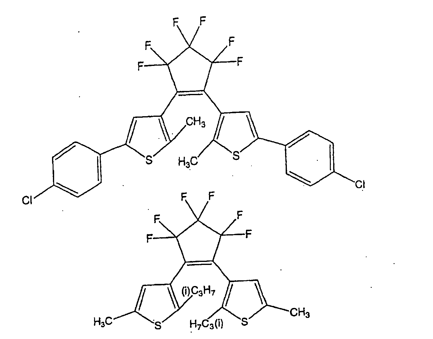
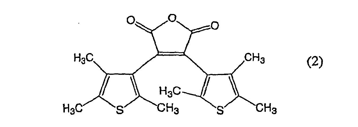
- a sample was prepared in the same manner as in Example 7 except that the diarylethene compound was changed to the following compound (2): and X-rays were irradiated in the same manner as in Example 7, whereby the sample underwent no color change.
- the change in absorbance at a wavelength of 600 nm was measured. The results are shown in Table 2. Further, with the sample employing the above compound (2), no change in absorbance was observed also in a case where 100 Gy of X-rays were irradiated.
- a white film was prepared in the same manner as in Example 9 except that the phosphor BaFCl:Eu 2 + was not used, and the change in reflectance at a wavelength of 645 nm was measured. The results are shown in Table 3.
- a diarylethene compound which shifts to a color-changed isomer when irradiated with a light in a specific wavelength band, is used in combination with an illuminant which emits a light having a wavelength band which overlaps the above-mentioned wavelength band upon absorption of a radiation, whereby the irradiated radiation can efficiently be detected, and it will be possible to measure the dose with high sensitivity.
Landscapes
- Chemical & Material Sciences (AREA)
- Spectroscopy & Molecular Physics (AREA)
- Life Sciences & Earth Sciences (AREA)
- General Physics & Mathematics (AREA)
- High Energy & Nuclear Physics (AREA)
- Molecular Biology (AREA)
- Physics & Mathematics (AREA)
- Health & Medical Sciences (AREA)
- Engineering & Computer Science (AREA)
- Materials Engineering (AREA)
- Organic Chemistry (AREA)
- Luminescent Compositions (AREA)
- Measurement Of Radiation (AREA)
Abstract
Description
Namely, the gist of the present invention resides in a photochromic material comprising an illuminant(s) which emits a light when irradiated with a radiation, and a diarylethene compound(s), wherein the diarylethene compound(s) is represented by the following formula (0), and the absorption spectrum of the ring opened form or the ring closed form of the diarylethene compound(s), and the emission spectrum of the illuminant(s), overlap each other:

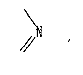
or a cycloalkyl group which may be substituted,
group R4 is a hydrogen atom, an alkyl group which may be substituted, or a cycloalkyl group which may be substituted,
ring D1 is a 5- or 6-membered aromatic ring which is formed by groups X1 and Y2 together with two carbon atoms bonded thereto and which may be substituted, and ring E1 is a 5- or 6-membered aromatic ring which is formed by groups X2 and Y2 together with two carbon atoms bonded thereto and which may be substituted,
rings D1 and E1 may further have a 5- or 6-membered aromatic ring which may be substituted, condensed thereto.

- 1, 1':
- support layer
- 2, 2':
- emission layer
- 3:
- photochromic layer
- 4:
- photochromic material
- 5:
- light blocking substrate
- 5':
- ultraviolet absorptive transparent substrate
- 6:
- adhesive layer or double-stick tape
- 7:
- release paper
- 8:
- ultraviolet absorptive transparent film
- 9
- opening or transparent portion containing an ultraviolet absorber
- 10, 11:
- laminate (color dose meter)
- 20:
- tag-form color dose meter
- 30:
- blood bag






















Claims (12)
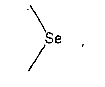
- A photochromic material comprising an illuminant(s) which emits a light when irradiated with a radiation, and a diarylethene compound(s), wherein the diarylethene compound(s) is represented by the following formula (0), and the absorption spectrum of the ring opened form or the ring closed form of the diarylethene compound(s), and the emission spectrum of the illuminant(s), overlap each other:in the above formula (0), each of groups R1 and R2 which are independent of each other, is an alkyl group, a cycloalkyl group or an alkoxy group, each of groups X1, X2, Y1 and Y2 which are independent of one another, is either one of
 and
and group R3 is a hydrogen atom, an alkyl group which may be substituted, an aryl group which may be substituted,
or a cycloalkyl group which may be substituted,
group R4 is a hydrogen atom, an alkyl group which may be substituted, or a cycloalkyl group which may be substituted,
ring D1 is a 5- or 6-membered aromatic ring which is formed by groups X1 and Y2 together with two carbon atoms bonded thereto and which may be substituted, and ring E1 is a 5- or 6-membered aromatic ring which is formed by groups X2 and Y2 together with two carbon atoms bonded thereto and which may be substituted,
rings D1 and E1 may further have a 5- or 6-membered aromatic ring which may be substituted, condensed thereto. - The photochromic material according to Claim 1, wherein the diarylethene compound(s) represented by the formula (0), is represented by the following formula (I):in the above formula (I), each of groups R11 and R12 which are independent of each other, is an alkyl group, a cycloalkyl group or an alkoxy group, each of groups X11 and X12 which are independent of each other, is either one of
 and
and each of groups Y11 and Y12 which are independent of each other, is either one of
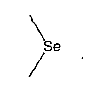 each of groups R15 and R16 which are independent of each other, is a hydrogen atom, an alkyl group which may be substituted, an aryl group which may be substituted, a heteroaryl group which may be substituted, or a cycloalkyl group which may be substituted,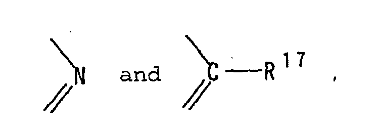
when group Y11 and/or group Y12 isgroup R15 and/or group R16 may be bonded to group R17 to form a 5- or 6-membered aromatic ring which may have a substituent,
group R13 is a hydrogen atom, an alkyl group which may be substituted, an aryl group which may be substituted, or a cycloalkyl group which may be substituted,
group R17 is a hydrogen atom, an alkyl group which may be substituted, or a cycloalkyl group which may be substituted. - The photochromic material according to Claim 1, wherein the diarylethene compound(s) represented by the formula (0), is represented by the following formula (II) :in the above formula (II), each of groups R21 and R22 which are independent of each other, is an alkyl group, a cycloalkyl group or an alkoxy group, each of groups X21 and X22 which are independent of each other, is either one of
 and
and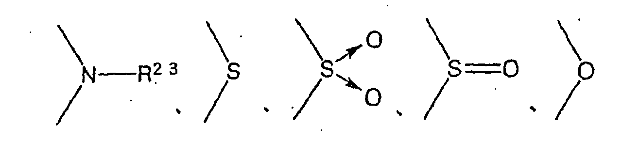 each of groups Y21 and Y22 which are independent of each other, is either one of
 each of groups R25 and R26 which are independent of each other, is a hydrogen atom, an alkyl group which may be substituted, an aryl group which may be substituted, a heteroaryl group which may be substituted, or a cycloalkyl group which may be substituted,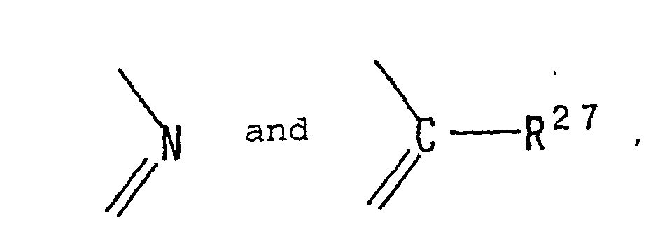
when group Y21 and/or group Y22 isgroup R25 and/or group R26 may be bonded to group R27 to form a 5- or 6-membered aromatic ring,
group R23 is a hydrogen atom, an alkyl group which may be substituted, an aryl group which may be substituted, or a cycloalkyl group which may be substituted,
group R27 is a hydrogen atom, an alkyl group which may be substituted, or a cycloalkyl group which may be substituted. - The photochromic material according to any one of Claims 1 to 3, wherein the diarylethene compound(s) is heat irreversible.
- The photochromic material according to any one of Claims 1 to 4, wherein the quantum yield in the ring opening reaction of the diarylethene compound(s) is at most 10-3.
- The photochromic material according to any one of Claims 1 to 5, wherein the illuminant(s) is an ultraviolet light emitting phosphor(s).
- The photochromic material according to any one of Claims 1 to 6, which is a composition comprising the illuminant(s) and the diarylethene compound(s).
- The photochromic material according to Claim 7, which further contains an ultraviolet absorber(s).
- The photochromic material according to any one of Claims 1 to 6, which is a laminate comprising a layer containing the illuminant(s) and a layer containing the diarylethene compound(s).
- A color dose meter prepared by using the photochromic material as defined in any one of Claims 1 to 9.
- The color dose meter according to Claim 10, which is in the form of a seal.
- The color dose meter according to Claim 10, which is in the form of a tag.
Applications Claiming Priority (3)
| Application Number | Priority Date | Filing Date | Title |
|---|---|---|---|
| JP2001181418 | 2001-06-15 | ||
| JP2001181418 | 2001-06-15 | ||
| PCT/JP2002/005972 WO2002102923A1 (en) | 2001-06-15 | 2002-06-14 | Photochromic material and color dose meter using the same |
Publications (3)
| Publication Number | Publication Date |
|---|---|
| EP1405891A1 true EP1405891A1 (en) | 2004-04-07 |
| EP1405891A4 EP1405891A4 (en) | 2009-03-11 |
| EP1405891B1 EP1405891B1 (en) | 2010-11-24 |
Family
ID=19021692
Family Applications (1)
| Application Number | Title | Priority Date | Filing Date |
|---|---|---|---|
| EP02736111A Expired - Lifetime EP1405891B1 (en) | 2001-06-15 | 2002-06-14 | Photochromic material and color dose meter using the same |
Country Status (4)
| Country | Link |
|---|---|
| US (1) | US7101497B2 (en) |
| EP (1) | EP1405891B1 (en) |
| DE (1) | DE60238405D1 (en) |
| WO (1) | WO2002102923A1 (en) |
Cited By (17)
| Publication number | Priority date | Publication date | Assignee | Title |
|---|---|---|---|---|
| EP1367111A4 (en) * | 2001-03-05 | 2005-03-09 | Japan Science & Tech Agency | PHOTO CHROMICAL MATERIAL |
| EP2003497A1 (en) * | 2007-06-13 | 2008-12-17 | Xerox Corporation | Inkless reimageable printing paper and method |
| US7541119B2 (en) | 2007-06-13 | 2009-06-02 | Xerox Corporation | Inkless reimageable printing paper and method |
| US7553603B2 (en) | 2007-06-13 | 2009-06-30 | Xerox Corporation | Inkless printing paper and method |
| US7569316B2 (en) | 2007-06-13 | 2009-08-04 | Xerox Corporation | Inkless reimageable printing paper and method |
| US7572560B2 (en) | 2007-06-13 | 2009-08-11 | Xerox Corporation | Inkless reimageable printing paper and method |
| US7572569B2 (en) | 2007-06-13 | 2009-08-11 | Xerox Corporation | Inkless printing paper and method |
| US7582398B2 (en) | 2007-06-13 | 2009-09-01 | Xerox Corporation | Inkless reimageable printing paper and method |
| US7588878B2 (en) | 2007-06-13 | 2009-09-15 | Xerox Corporation | Inkless printing paper and method |
| EP2138894A1 (en) * | 2008-06-24 | 2009-12-30 | Xerox Corporation | Photochromic medium with erase-on-demand capability |
| US7645560B1 (en) | 2008-09-08 | 2010-01-12 | Xerox Corporation | Inkless reimageable printing paper and method |
| US7655366B2 (en) | 2007-06-13 | 2010-02-02 | Xerox Corporation | Inkless reimageable printing paper and method |
| US7666558B2 (en) | 2007-06-13 | 2010-02-23 | Xerox Corporation | Inkless reimageable printing paper and method |
| US7718325B2 (en) | 2007-06-13 | 2010-05-18 | Xerox Corporation | Photochromic material, inkless reimageable printing paper, and methods |
| US7852366B2 (en) | 2007-06-13 | 2010-12-14 | Xerox Corporation | System and method for printing reimageable transient documents |
| US7867672B2 (en) | 2007-06-13 | 2011-01-11 | Xerox Corporation | Reimageable paper protected against UV light |
| FR3053476A1 (en) * | 2016-07-01 | 2018-01-05 | Electricite De France | DEVICE FOR VISUALIZING THE IRRADIATION LEVEL |
Families Citing this family (26)
| Publication number | Priority date | Publication date | Assignee | Title |
|---|---|---|---|---|
| GB0214989D0 (en) | 2002-06-28 | 2002-08-07 | Qinetiq Ltd | Photochromic liquid crystals |
| US7777055B2 (en) * | 2002-08-09 | 2010-08-17 | Switch Materials Inc. | Photochromic and electrochromic compounds and methods of synthesizing and using same |
| CA2495304C (en) * | 2002-08-14 | 2011-10-25 | Jp Laboratories, Inc. | Thick radiation sensitive devices |
| JP4469336B2 (en) * | 2003-05-28 | 2010-05-26 | パナソニック株式会社 | Information recording medium, manufacturing method thereof, recording / reproducing method, and optical information recording / reproducing apparatus |
| EP1637573A4 (en) * | 2003-06-24 | 2008-05-28 | Asahi Glass Co Ltd | OPTICAL RECORDING MATERIAL |
| WO2005075978A2 (en) * | 2004-02-02 | 2005-08-18 | Freshpoint Holdings Sa | Time-temperature indicator based on valence isomerizations |
| US7897296B2 (en) * | 2004-09-30 | 2011-03-01 | General Electric Company | Method for holographic storage |
| JP4790258B2 (en) * | 2004-12-01 | 2011-10-12 | 矢崎総業株式会社 | Removal position display adhesive tape |
| CA2609887C (en) * | 2005-05-25 | 2015-12-29 | Switch Materials Inc. | Photochromic and electrochromic compounds and synthesis and use thereof |
| US7956334B2 (en) * | 2006-03-13 | 2011-06-07 | School Corporation, Azabu University Medicine Educational Institution | Radiation dosimeter for fluid very small substances, and method of measuring radiation dose |
| US7785299B2 (en) * | 2006-05-08 | 2010-08-31 | Becton, Dickinson And Company | Vascular access device time sensitive status indication |
| FR2942403A1 (en) * | 2009-02-23 | 2010-08-27 | Oreal | PHOTOMAQUILING METHOD WITH APPLICATION OF A BASE LAYER AND ASSEMBLY FOR IMPLEMENTING SUCH A METHOD |
| FR2942407B1 (en) * | 2009-02-23 | 2011-08-05 | Oreal | PHOTOMAQUILLING METHOD AND PHOTOMAQUILING COMPOSITION |
| FR2942400B1 (en) * | 2009-02-23 | 2011-04-22 | Oreal | PHOTOMAKING METHOD IN WHICH OPTICAL AGENT IS USED TO PROTECT THE RESULT OBTAINED |
| US8288949B2 (en) * | 2009-04-29 | 2012-10-16 | General Electric Company | Fluorescent lamp with protective sleeve |
| US8053962B2 (en) * | 2009-05-04 | 2011-11-08 | General Electric Company | Fluorescent lamp with UV-blocking layer and protective sleeve |
| US8420297B2 (en) * | 2010-08-20 | 2013-04-16 | Eastman Kodak Company | Developers and method of coloring lithographic printing members |
| DE102010053723A1 (en) * | 2010-11-30 | 2012-05-31 | Fraunhofer-Gesellschaft zur Förderung der angewandten Forschung e.V. | Method for non-destructive monitoring or detection of implementation of sterilization during e.g. production of prostheses, has performing comparison with reference value and/or wavelength to find whether preset energy input is carried out |
| CN103890133A (en) | 2011-09-30 | 2014-06-25 | 思维奇材料公司 | Photochromic and Electrochromic Diarylcyclopentene Derivatives as Optical Filters |
| JP5920780B2 (en) * | 2012-07-10 | 2016-05-18 | 公立大学法人大阪市立大学 | Photochromic material and difunctional device containing diarylethene compound |
| US9738675B2 (en) * | 2012-09-11 | 2017-08-22 | Rikkyo Educational Corporation | Water-soluble photochromic compound |
| JP6936252B2 (en) * | 2016-02-02 | 2021-09-15 | 8996598 カナダ インコーポレイテッド | Methods and devices for detecting exposure to ultraviolet light |
| CN107011317B (en) | 2016-05-24 | 2020-03-20 | 北京大学 | Photoisomerizable compounds and devices comprising same |
| KR102611794B1 (en) * | 2016-11-30 | 2023-12-07 | 엘지디스플레이 주식회사 | Organic light emitting display device and method for manufacturing the same |
| US12123775B2 (en) | 2017-05-11 | 2024-10-22 | 15814057 Canada Inc. | Method and apparatus for the detection of exposure to ultraviolet light |
| RU2721095C1 (en) * | 2019-11-06 | 2020-05-15 | Федеральное государственное бюджетное учреждение науки Институт физики твердого тела Российской академии наук (ИФТТ РАН) | Inorganic photochromic material with spatially selective memory effect |
Family Cites Families (10)
| Publication number | Priority date | Publication date | Assignee | Title |
|---|---|---|---|---|
| JPH02216493A (en) | 1989-02-17 | 1990-08-29 | Mitsubishi Atom Power Ind Inc | Radiation sensitive display sheet |
| US5604626A (en) * | 1995-02-10 | 1997-02-18 | Donnelly Corporation | Photochromic devices |
| JP3956420B2 (en) | 1997-03-07 | 2007-08-08 | 入江 正浩 | Visible transparent photochromic material |
| JPH10251251A (en) * | 1997-03-10 | 1998-09-22 | Masahiro Irie | Molecular magnetic material |
| US6060321A (en) * | 1997-07-11 | 2000-05-09 | Hovorka; George B. | Sun tan dosimeter |
| JP3646504B2 (en) | 1998-03-13 | 2005-05-11 | 入江 正浩 | Photochromic color dosimeter |
| US6168892B1 (en) * | 1998-06-15 | 2001-01-02 | Konica Corporation | Method for forming color image |
| JP2000256663A (en) * | 1999-03-11 | 2000-09-19 | Masahiro Irie | Light-induced phase change organic materials |
| JP2001049244A (en) * | 1999-08-04 | 2001-02-20 | Minolta Co Ltd | Photochromic material and optical recording medium |
| US6359150B1 (en) * | 1999-08-31 | 2002-03-19 | Kyocera Corporation | Photochromic compound and optical function device using the same |
-
2002
- 2002-06-14 DE DE60238405T patent/DE60238405D1/en not_active Expired - Lifetime
- 2002-06-14 US US10/479,982 patent/US7101497B2/en not_active Expired - Fee Related
- 2002-06-14 WO PCT/JP2002/005972 patent/WO2002102923A1/en not_active Ceased
- 2002-06-14 EP EP02736111A patent/EP1405891B1/en not_active Expired - Lifetime
Cited By (20)
| Publication number | Priority date | Publication date | Assignee | Title |
|---|---|---|---|---|
| EP1367111A4 (en) * | 2001-03-05 | 2005-03-09 | Japan Science & Tech Agency | PHOTO CHROMICAL MATERIAL |
| US7057054B2 (en) | 2001-03-05 | 2006-06-06 | Japan Science And Technology Corporation | Photochromic material |
| US7718325B2 (en) | 2007-06-13 | 2010-05-18 | Xerox Corporation | Photochromic material, inkless reimageable printing paper, and methods |
| US7645558B2 (en) | 2007-06-13 | 2010-01-12 | Xerox Corporation | Inkless reimageable printing paper and method |
| US7553603B2 (en) | 2007-06-13 | 2009-06-30 | Xerox Corporation | Inkless printing paper and method |
| US7569316B2 (en) | 2007-06-13 | 2009-08-04 | Xerox Corporation | Inkless reimageable printing paper and method |
| US7572560B2 (en) | 2007-06-13 | 2009-08-11 | Xerox Corporation | Inkless reimageable printing paper and method |
| US7572569B2 (en) | 2007-06-13 | 2009-08-11 | Xerox Corporation | Inkless printing paper and method |
| US7582398B2 (en) | 2007-06-13 | 2009-09-01 | Xerox Corporation | Inkless reimageable printing paper and method |
| US7588878B2 (en) | 2007-06-13 | 2009-09-15 | Xerox Corporation | Inkless printing paper and method |
| US7867672B2 (en) | 2007-06-13 | 2011-01-11 | Xerox Corporation | Reimageable paper protected against UV light |
| US7541119B2 (en) | 2007-06-13 | 2009-06-02 | Xerox Corporation | Inkless reimageable printing paper and method |
| US7852366B2 (en) | 2007-06-13 | 2010-12-14 | Xerox Corporation | System and method for printing reimageable transient documents |
| US7655366B2 (en) | 2007-06-13 | 2010-02-02 | Xerox Corporation | Inkless reimageable printing paper and method |
| US7666558B2 (en) | 2007-06-13 | 2010-02-23 | Xerox Corporation | Inkless reimageable printing paper and method |
| EP2003497A1 (en) * | 2007-06-13 | 2008-12-17 | Xerox Corporation | Inkless reimageable printing paper and method |
| EP2138894A1 (en) * | 2008-06-24 | 2009-12-30 | Xerox Corporation | Photochromic medium with erase-on-demand capability |
| US7964271B2 (en) | 2008-06-24 | 2011-06-21 | Xerox Corporation | Photochromic medium with erase-on-demand capability |
| US7645560B1 (en) | 2008-09-08 | 2010-01-12 | Xerox Corporation | Inkless reimageable printing paper and method |
| FR3053476A1 (en) * | 2016-07-01 | 2018-01-05 | Electricite De France | DEVICE FOR VISUALIZING THE IRRADIATION LEVEL |
Also Published As
| Publication number | Publication date |
|---|---|
| EP1405891B1 (en) | 2010-11-24 |
| US20040178394A1 (en) | 2004-09-16 |
| US7101497B2 (en) | 2006-09-05 |
| DE60238405D1 (en) | 2011-01-05 |
| EP1405891A4 (en) | 2009-03-11 |
| WO2002102923A1 (en) | 2002-12-27 |
Similar Documents
| Publication | Publication Date | Title |
|---|---|---|
| EP1405891B1 (en) | Photochromic material and color dose meter using the same | |
| JP3882746B2 (en) | Diarylethene compounds, photochromic materials, color dosimeters and optical memory devices | |
| US4491736A (en) | Radiation image storage panel | |
| JP2005082507A (en) | Diarylethene compounds, photochromic materials, color dosimeters and optical memory devices | |
| JPS59139000A (en) | Radiation image conversion panel | |
| JPS5937039B2 (en) | Scintillator object and its manufacturing method | |
| JP4190212B2 (en) | Photochromic material and color dosimeter using the same | |
| US6652994B2 (en) | Radiation image conversion panel | |
| JPS63262600A (en) | Radiation picture conversion panel and manufacture thereof | |
| JP2002285146A (en) | Photochromic composition and dosimeter | |
| JPS59162498A (en) | Radiation image conversion panel | |
| JPS60200200A (en) | Radiation image converting panel | |
| US4863826A (en) | Radiation image storage panel | |
| JP4238075B2 (en) | Photochromic composition and radiation indicator using the same | |
| EP1462824A1 (en) | Method for manufacturing radiographic image conversion panel and radiographic image conversion panel | |
| JP2005008754A (en) | Photochromic composition and radiation indicator using the same | |
| EP0363977A1 (en) | Magnesium tantalum oxide x-ray intensifying screens | |
| EP1465208A2 (en) | Radiographic image conversion panel and method for its production | |
| JPS6198787A (en) | Radiation image-conversion method, and radiation image-conversion panel used therefor | |
| JPH02276998A (en) | Radiation image converting panel | |
| JP2002131493A (en) | Radiation image conversion panel | |
| JPS6293700A (en) | Radiation image conversion panel | |
| JPH02287200A (en) | Radiation image conversion panel | |
| JP2002365398A (en) | Radiographic image conversion panel | |
| JPS63188800A (en) | Radiation image conversion panel and manufacture thereof |
Legal Events
| Date | Code | Title | Description |
|---|---|---|---|
| PUAI | Public reference made under article 153(3) epc to a published international application that has entered the european phase |
Free format text: ORIGINAL CODE: 0009012 |
|
| 17P | Request for examination filed |
Effective date: 20031211 |
|
| AK | Designated contracting states |
Kind code of ref document: A1 Designated state(s): AT BE CH CY DE DK ES FI FR GB GR IE IT LI LU MC NL PT SE TR |
|
| AX | Request for extension of the european patent |
Extension state: AL LT LV MK RO SI |
|
| A4 | Supplementary search report drawn up and despatched |
Effective date: 20090211 |
|
| 17Q | First examination report despatched |
Effective date: 20090522 |
|
| R17C | First examination report despatched (corrected) |
Effective date: 20090605 |
|
| GRAP | Despatch of communication of intention to grant a patent |
Free format text: ORIGINAL CODE: EPIDOSNIGR1 |
|
| GRAJ | Information related to disapproval of communication of intention to grant by the applicant or resumption of examination proceedings by the epo deleted |
Free format text: ORIGINAL CODE: EPIDOSDIGR1 |
|
| GRAP | Despatch of communication of intention to grant a patent |
Free format text: ORIGINAL CODE: EPIDOSNIGR1 |
|
| RBV | Designated contracting states (corrected) |
Designated state(s): BE DE ES FR IT NL |
|
| GRAS | Grant fee paid |
Free format text: ORIGINAL CODE: EPIDOSNIGR3 |
|
| GRAA | (expected) grant |
Free format text: ORIGINAL CODE: 0009210 |
|
| AK | Designated contracting states |
Kind code of ref document: B1 Designated state(s): BE DE ES FR IT NL |
|
| REF | Corresponds to: |
Ref document number: 60238405 Country of ref document: DE Date of ref document: 20110105 Kind code of ref document: P |
|
| REG | Reference to a national code |
Ref country code: NL Ref legal event code: VDEP Effective date: 20101124 |
|
| PG25 | Lapsed in a contracting state [announced via postgrant information from national office to epo] |
Ref country code: NL Free format text: LAPSE BECAUSE OF FAILURE TO SUBMIT A TRANSLATION OF THE DESCRIPTION OR TO PAY THE FEE WITHIN THE PRESCRIBED TIME-LIMIT Effective date: 20101124 |
|
| PG25 | Lapsed in a contracting state [announced via postgrant information from national office to epo] |
Ref country code: ES Free format text: LAPSE BECAUSE OF FAILURE TO SUBMIT A TRANSLATION OF THE DESCRIPTION OR TO PAY THE FEE WITHIN THE PRESCRIBED TIME-LIMIT Effective date: 20110307 Ref country code: BE Free format text: LAPSE BECAUSE OF FAILURE TO SUBMIT A TRANSLATION OF THE DESCRIPTION OR TO PAY THE FEE WITHIN THE PRESCRIBED TIME-LIMIT Effective date: 20101124 |
|
| PLBE | No opposition filed within time limit |
Free format text: ORIGINAL CODE: 0009261 |
|
| STAA | Information on the status of an ep patent application or granted ep patent |
Free format text: STATUS: NO OPPOSITION FILED WITHIN TIME LIMIT |
|
| 26N | No opposition filed |
Effective date: 20110825 |
|
| REG | Reference to a national code |
Ref country code: DE Ref legal event code: R097 Ref document number: 60238405 Country of ref document: DE Effective date: 20110825 |
|
| PG25 | Lapsed in a contracting state [announced via postgrant information from national office to epo] |
Ref country code: IT Free format text: LAPSE BECAUSE OF FAILURE TO SUBMIT A TRANSLATION OF THE DESCRIPTION OR TO PAY THE FEE WITHIN THE PRESCRIBED TIME-LIMIT Effective date: 20101124 |
|
| PGFP | Annual fee paid to national office [announced via postgrant information from national office to epo] |
Ref country code: DE Payment date: 20130612 Year of fee payment: 12 |
|
| PGFP | Annual fee paid to national office [announced via postgrant information from national office to epo] |
Ref country code: FR Payment date: 20130624 Year of fee payment: 12 |
|
| REG | Reference to a national code |
Ref country code: DE Ref legal event code: R119 Ref document number: 60238405 Country of ref document: DE |
|
| REG | Reference to a national code |
Ref country code: DE Ref legal event code: R119 Ref document number: 60238405 Country of ref document: DE Effective date: 20150101 |
|
| REG | Reference to a national code |
Ref country code: FR Ref legal event code: ST Effective date: 20150227 |
|
| PG25 | Lapsed in a contracting state [announced via postgrant information from national office to epo] |
Ref country code: DE Free format text: LAPSE BECAUSE OF NON-PAYMENT OF DUE FEES Effective date: 20150101 |
|
| PG25 | Lapsed in a contracting state [announced via postgrant information from national office to epo] |
Ref country code: FR Free format text: LAPSE BECAUSE OF NON-PAYMENT OF DUE FEES Effective date: 20140630 |