EP1405781A1 - Electronic control power steering device - Google Patents
Electronic control power steering device Download PDFInfo
- Publication number
- EP1405781A1 EP1405781A1 EP02743852A EP02743852A EP1405781A1 EP 1405781 A1 EP1405781 A1 EP 1405781A1 EP 02743852 A EP02743852 A EP 02743852A EP 02743852 A EP02743852 A EP 02743852A EP 1405781 A1 EP1405781 A1 EP 1405781A1
- Authority
- EP
- European Patent Office
- Prior art keywords
- gear
- motor
- rack
- shaft
- power steering
- Prior art date
- Legal status (The legal status is an assumption and is not a legal conclusion. Google has not performed a legal analysis and makes no representation as to the accuracy of the status listed.)
- Withdrawn
Links
Images






Classifications
-
- B—PERFORMING OPERATIONS; TRANSPORTING
- B62—LAND VEHICLES FOR TRAVELLING OTHERWISE THAN ON RAILS
- B62D—MOTOR VEHICLES; TRAILERS
- B62D5/00—Power-assisted or power-driven steering
- B62D5/04—Power-assisted or power-driven steering electrical, e.g. using an electric servo-motor connected to, or forming part of, the steering gear
- B62D5/0442—Conversion of rotational into longitudinal movement
- B62D5/0445—Screw drives
- B62D5/0448—Ball nuts
-
- B—PERFORMING OPERATIONS; TRANSPORTING
- B62—LAND VEHICLES FOR TRAVELLING OTHERWISE THAN ON RAILS
- B62D—MOTOR VEHICLES; TRAILERS
- B62D5/00—Power-assisted or power-driven steering
- B62D5/04—Power-assisted or power-driven steering electrical, e.g. using an electric servo-motor connected to, or forming part of, the steering gear
- B62D5/0421—Electric motor acting on or near steering gear
-
- Y—GENERAL TAGGING OF NEW TECHNOLOGICAL DEVELOPMENTS; GENERAL TAGGING OF CROSS-SECTIONAL TECHNOLOGIES SPANNING OVER SEVERAL SECTIONS OF THE IPC; TECHNICAL SUBJECTS COVERED BY FORMER USPC CROSS-REFERENCE ART COLLECTIONS [XRACs] AND DIGESTS
- Y10—TECHNICAL SUBJECTS COVERED BY FORMER USPC
- Y10T—TECHNICAL SUBJECTS COVERED BY FORMER US CLASSIFICATION
- Y10T74/00—Machine element or mechanism
- Y10T74/19—Gearing
- Y10T74/19642—Directly cooperating gears
- Y10T74/19698—Spiral
- Y10T74/19702—Screw and nut
- Y10T74/19744—Rolling element engaging thread
- Y10T74/19749—Recirculating rolling elements
Definitions
- the present invention relates to an electric power steering apparatus that applies an assist force generated by a motor to a vehicle steering system.
- a rack-and-pinion steering apparatus is one type of known steering apparatuses for vehicles.
- a steering wheel is connected to a pinion shaft having pinion teeth, and the pinion shaft rotates as the steering wheel is rotated.
- the pinion teeth of the pinion shaft mesh with rack teeth of a rack shaft, and the rack shaft moves along its axis as the pinion shaft rotates.
- the two ends of the rack shaft are connected to two steered wheels (front wheels) by tie rods, respectively.
- the steering angle of the steered wheels changes as the rack shaft moves in its axial direction.
- An electric power steering apparatus including the known rack-and-pinion steering apparatus has an auxiliary motor and a ball screw mechanism for assisting the axial movement of the rack shaft.
- the ball screw mechanism includes a ball screw nut having a helical ball groove in its inner circumference, a helical ball groove provided in the outer circumference of the rack shaft, and a plurality of balls interposed between the two ball grooves. The ball screw nut and the balls convert the rotation of the motor into axial movement of the rack shaft.
- a first prior art of an electric power steering apparatus which includes a reduction mechanism for transmitting the rotation of a motor to a ball screw nut while reducing the speed of the rotation, is described in Japanese Laid Open Patent Publications Nos. 60-25853 and 8-99643.
- the reduction mechanism includes two spur gears which mesh with each other.
- One of the spur gears is connected to the rotating shaft of the motor, and the other one of the spur gears is fixed to a ball screw nut of a ball screw mechanism.
- the motor is arranged parallel to the rack shaft.
- the steering apparatus includes a reduction mechanism including a worm and a worm wheel that mesh with each other.
- the worm is connected to a rotating shaft of a motor, and the worm wheel is fixed to a ball screw nut of a ball screw mechanism.
- the rotating shaft of the motor is arranged perpendicular to the rack shaft.
- the steering apparatus includes a rack shaft, a stator having a coil that covers the rack shaft, and a rotor arranged coaxially with the rack shaft. The rotation of the rotor is converted into the movement of the rack shaft by a ball screw.
- the rotating shaft of the motor can only be arranged parallel to the rack shaft.
- the rotating shaft of the motor can only be arranged perpendicular to the rack shaft. Therefore, the power steering apparatuses of the first and second prior arts have problems in that the motor interferes with the installation of other devices of the vehicle and the freedom of design in determining positions for installing other devices is restricted.
- the rack shaft, the stator, and the rotor are retained in a rack housing.
- the rack housing which is relatively large, results in problems in that the rack housing interferes with the installation of other devices of the vehicle (the engine, transmission, etc.) and the amount of freedom of design in determining positions for installing other devices is restricted.
- fastening means such as bolts and nuts, integrally connects a casing retaining the electric motor to a housing, which retains a power-assist unit for transmitting the power of the electric motor to a steering gear mechanism. Therefore, there is a problem in that the vibration and noise of the electric motor are transmitted to the steering apparatus through the housing retaining the power assist unit and ultimately transmitted to the driver and the passenger compartment.
- Japanese Laid Open Patent Publication No. 2000-350397 describes an electric power steering apparatus in which an electric motor and a housing are connected to each other by a bushing.
- the bushing has a metal body covered slightly by a rubber elastic member.
- the electric motor and the housing are connected to each other only by the metal body, and the transmission of vibration and noise of the electric motor cannot be blocked sufficiently.
- the electric motor is supported by the elastic member in a floating manner with respect to the housing, and rattling of the electric motor may occur due to the floating support.
- the electric motor rattles, there is a risk of the rotating shaft of the electric motor applying excessive force to the power transmission shaft of the power assist unit, and therefore the power assist unit cannot be operated smoothly.
- one aspect of the present invention provides an electric power steering apparatus which transmits a driving force of a motor to a rack shaft via a reduction mechanism and a ball screw mechanism to assist movement of the rack shaft in the longitudinal axis of the rack shaft.
- the reduction mechanism includes a drive gear connected to a rotating shaft of the motor and a driven gear which meshes with the drive gear and which is connected to the ball screw mechanism.
- the rotating shaft of the motor intersects the longitudinal axis of the rack shaft at an arbitrary angle.
- the electric power steering apparatus 11 includes a hollow rack housing 13 which is provided with two attachments 12, each formed on one of the two ends of the steering apparatus 11.
- the power steering apparatus 11 is attached to a vehicle body (not shown) by fixing the attachments 12 to the vehicle body with screws.
- the rack housing 13 supports a nut-retaining sleeve 16 with first and second bearings 14 and 15 so that rotation of the nut-retaining sleeve 16 is enabled but longitudinal movement of the nut-retaining sleeve 16 is disabled.
- the nut-retaining sleeve 16 has a large-diameter portion on the end near the center S of the rack housing 13 in the longitudinal direction of the rack housing 13. A nut 17 is fitted into the large-diameter portion.
- a female thread is formed at the end of the large-diameter portion, and a lock screw 22 is engaged with the female thread.
- the nut 17 is pressed against a stepped portion of the large-diameter portion by the lock screw 22.
- the nut-retaining sleeve 16 and the nut 17 define a ball screw nut 20.
- the ball screw nut 20 covers part of a rack shaft 18.
- a first ball groove 17a is formed helically in the inner circumferential surface of the nut 17.
- a second ball groove 18a is formed helically in the rack shaft 18 for a predetermined length in the longitudinal direction of the rack shaft 18.
- the first ball groove 17a faces the second ball groove 18a at the central region of the second ball groove 18a.
- a plurality of balls 19 are received between the first ball groove 17a and the second ball groove 18a in a manner that rolling of the balls 19 is enabled.
- the ball screw nut 20, the second ball groove 18a, and the balls 19 define a ball screw mechanism 21.
- a pinion shaft sleeve 26 is provided at the right of the center S of the rack housing 13, preferably in the vicinity of the right end of the rack housing 13.
- a pinion shaft 25 is rotatably disposed in the pinion shaft sleeve 26.
- the pinion shaft 25 is arranged near the end of the rack housing 13.
- the rotation of a steering wheel H rotates the pinion shaft 25.
- the axis P of the pinion shaft 25 is inclined at an angle ⁇ 1 with respect to the axis O of the rack housing 13 (the rack shaft 18).
- the angle ⁇ 1 is about 70 degrees.
- a pinion gear 25a which meshes with the rack teeth 18b, is formed on the basal end of the pinion shaft 25.
- the rack teeth 18b and the pinion gear 25a define a rack-and-pinion mechanism. Rotation of the steering wheel H rotates the pinion shaft 25 and the pinion gear 25a and moves the rack shaft 18 having the rack teeth 18b along the axis O. Movement of the rack shaft 18 changes the steering angle of the front wheels (not shown).
- a motor sleeve 27 used for attaching a motor 28 is provided at a position on the left of the center S of the rack housing 13, preferably in the vicinity of the left end of the rack housing 13. Accordingly, the motor 28 is arranged so as to face the pinion shaft sleeve 26 across the center S of the rack housing 13. As shown in Fig. 3, a rotating shaft 28a of the motor 28 is inserted in the motor sleeve 27.
- the axis M of the motor 28 (rotating shaft 28a) is inclined at an angle ⁇ 2 with respect to the axis O of the rack shaft 18. In the first embodiment, the angle ⁇ 2 is about 70 degrees.
- a first screw gear 29, or a drive gear is connected to the distal end of the rotating shaft 28a.
- the first screw gear 29 is rotatably supported by third and fourth bearings 30 and 31, which are fixed to the motor sleeve 27.
- a second screw gear 16a, or a driven gear which meshes with the first screw gear 29, is formed on the outer circumferential surface of the nut-retaining sleeve 16 near the left end of the nut-retaining sleeve 16.
- the first screw gear 29 is coaxial with the rotating shaft 28a.
- the first screw gear 29 is in contact with the second screw gear 16a inclined at an angle of about 70 degrees.
- the first screw gear 29 and the second screw gear 16a define a reduction mechanism G (screw gear mechanism).
- a reference line T which extends through the center S of the rack housing 13 and which is perpendicular to the axis O is shown in Fig. 2.
- the axis P and the axis M are symmetric to each other about the reference line T.
- the pinion shaft 25 and the motor 28 are arranged on the same plane.
- Both the angle between the axis P and the reference line T and the angle between the axis M and the reference line T are about 20 degrees. Accordingly, the distance between the motor 28 and the pinion shaft 25 increases as the height from the rack housing 13 increases.
- the rotating shaft 28a of the motor 28 rotates in both forward and reverse directions.
- the driving force of the motor 28 is transmitted to the nut-retaining sleeve 16 via the first screw gear 29 and the second screw gear 16a.
- the ball screw mechanism 21 converts the rotational torque of the nut-retaining sleeve 16 into an assist force for the reciprocating movement of the rack shaft 18 along the axis O. Due to this assist force, the steering force applied to the steering wheel H is reduced.
- the power steering apparatus 11 according to the first embodiment has the advantages described below.
- the first embodiment may also be modified as follows.
- the angle ⁇ 2 between the axis M of the motor 28 and the axis O of the rack shaft 18 is not limited to about 70 degrees. As the angle ⁇ 2 increases, that is, as the upper end of the motor 28 is positioned further away from the center, the space available for installing the engine, the transmission, etc. increases.
- the axis P and the axis M do not have to lie along the same plane.
- the axis M may be rotated by a predetermined angle (for example, 90 degrees) with respect to the axis O.
- a predetermined angle for example, 90 degrees
- the motor 28 and the pinion shaft 25 may be arranged with a relatively large degree of freedom in accordance with the other devices that are installed in the vehicle.
- the second screw gear 16a may be formed separately from the nut-retaining sleeve 16 and attached to the nut-retaining sleeve 16.
- the power steering apparatus 100 includes a steering gear mechanism 109, which is formed based on a rack-and-pinion gear mechanism, and a power-assist unit 105, which has an electric motor 103.
- the steering gear mechanism 109 includes a rack shaft 106 and a pinion gear 191, which is connected to a steering shaft (not shown).
- a ball screw mechanism 166 is formed between the rack shaft 106 and a ball nut 162.
- the power-assist unit 105 includes a transmission mechanism (reduction mechanism) 101 for transmitting the power of the motor 103 to the rack shaft 106.
- the transmission mechanism 101 is a bevel gear mechanism including a driven bevel gear 161, which integrally retains the ball nut 162 with a retainer by means of a key 169, and a drive bevel gear 111, which meshes with the driven bevel gear 161.
- the motor 103 is connected to the rotating shaft of the drive bevel gear 111 by a coupling 102.
- the transmission mechanism 101 of the second embodiment is an angular bevel gear mechanism in which the rotational axis of the motor 103 intersects the center axis of the rack shaft 106 at a predetermined angle, which excludes a right angle.
- the transmission mechanism 101 may also be a miter gear mechanism in which the intersection angle is 90 degrees.
- the driven bevel gear 161 may also be formed integrally with the ball nut 162.
- the steering gear mechanism 109 and the power-assist unit 105 are arranged at different positions. More specifically, the pinion gear 191 and the power-assist unit 105 are separated from each other along the axis of the rack shaft 106 and lie along the same plane in a generally symmetric manner. Since the power-assist unit 105 is separated from the pinion gear 191, the power steering apparatus 100 is well-balanced. In addition, the structure around the pinion gear 191, where various components related to the steering gear mechanism 109 are arranged in a concentrated manner, is simplified. This enables the space around the steering gear mechanism 109 to be used effectively. In addition, when the installation position of the steering wheel is changed between left and right in accordance with where the vehicle is shipped to or for other reasons, the necessary changes in the power steering apparatus 100 can be made quickly.
- the rotating shaft of the motor 103 is connected to the relatively compact drive bevel gear 111 by the coupling 102, which may be an Oldham coupling.
- the drive bevel gear 111 meshes with the driven bevel gear 161.
- the driven bevel gear 161 is connected to the ball nut 162 by means of the key 169, and the ball nut 162 is connected to the rack shaft 106 by means of the ball screw mechanism 166. Accordingly, the driven bevel gear 161, the ball nut 162, and the rack shaft 106 are coaxial.
- the driven bevel gear 161 includes a ring portion 611 having teeth and a boss portion 612, contacts the key 169.
- a damper 615 composed of an elastic material such as rubber is arranged between the ring portion 611 and the boss portion 612.
- the cylindrical damper 615 is press-fitted between the ring portion 611 and the boss portion 612, or is formed by adhering an elastic body through vulcanization.
- the damper 615 serves to reduce the rattling noise generated by the bevel gears 111 and 161 and absorb impacts applied in the axial direction of the rack shaft 106 or around the bevel gear mechanism due to, for example, reverse input from the steered wheels.
- a collar 115 is attached to the shaft of the drive bevel gear 111, and a collar 165 is arranged adjacent to the driven bevel gear 161.
- the thicknesses of the collars 115 and 165 are adjusted such that the intersecting point X of the axis O of the drive bevel gear 111 (rotational centerline of the motor 103) and the axis O of the driven bevel gear 161 (rotational centerline of the rack shaft 106) is at a predetermined position on the axis of the rack shaft 106 and the backlash between the bevel gears 111 and 161 is set to an optimum value.
- the backlash between the collars 115 and 165 is always set at an optimum value regardless of differences between production lots.
- the power steering apparatus 100 of the second embodiment has the advantages described below.
- the transmission mechanism 101 includes a miter gear mechanism
- the intersection angle between the central axes of the two gears is limited to a right angle.
- the advantages described above in items (11) to (17) are obtained.
- the power steering apparatus 200 includes a rack-and-pinion steering gear mechanism 209 and a power-assist unit 208 having an electric motor 203.
- the steering gear mechanism 209 includes a steering shaft (not shown) and a pinion gear 291, which is connected to a rack shaft 206.
- the pinion gear 291 and the power-assist unit 208 are arranged at different positions. More specifically, the pinion gear 291 and the power-assist unit 208 are separated from each other along the axis of the rack shaft 206 and lie along the same plane in a generally symmetric manner. Since the power-assist unit 208 is separated from the pinion gear 291, the power steering apparatus 200 is well-balanced. In addition, the structure around the pinion gear 291, where various components related to the steering gear mechanism 209 are arranged in a concentrated manner, may be simplified. Thus, the space around the steering gear mechanism 209 may be used effectively. In addition, when the installation position of the steering wheel is changed between the left and right due to a change in where the vehicle is shipped to or the like, the necessary changes in the power steering apparatus 200 may be made quickly.
- a rotating shaft 231 of the electric motor 203 is connected to a rotating shaft 211 of a drive gear (small screw gear) 201 by a coupling 202.
- the drive gear 201 meshes with a driven gear (screw gear) 261, which is formed integrally with a ball nut 262.
- the drive gear 201 and the driven gear 261 define a reduction mechanism.
- a casing 235 of the electric motor 203 is fixed to a housing 215, which accommodates the small screw gear 201 and the coupling 202, by means of an elastic member 205 having a predetermined thickness.
- the rotating shaft 231 of the electric motor 203 is connected to the rotating shaft 211 of the small screw gear 201 by the Oldham coupling 202.
- the elastic member 205 which has the predetermined thickness, is arranged between a flange 355 of the casing 235, which accommodates the electric motor 203, and a flange 245 of the housing 215, which accommodates the small screw gear 201.
- the flanges 245 and 355 are fixed to each other by fastening means 55 such as bolts.
- the Oldham coupling 202 serves to absorb the influence of misalignment of the axes.
- a flexible coupling 202a composed of metal may also be used in place of the Oldham coupling 202.
- the flexible coupling 202a is formed by a plurality of flexible metal rings (metal-ring aggregate) arranged between the motor rotating shaft 231 and the rotating shaft 211 of the small screw gear 201. Since the metal rings can be inclined, although only slightly, with respect to one another, the entire body of the flexible coupling 202a may be deformed by a predetermined amount. Accordingly, even when the axis of the motor rotating shaft 231 and that of the rotating shaft 211 of the small screw gear 201 are misaligned or tilted with respect to each other, the flexible coupling 202a can cope with such conditions.
- the elastic member 205 which has the predetermined thickness, is arranged between the flange 355 of the casing 235 and the flange 245 of the housing 215.
- the elastic member 205 is in contact with the entire surfaces of the flanges 245 and 355.
- the elastic member 205 has a collar-receiving hole 511.
- a collar 251 having an outer diameter that is substantially the same as the inner diameter of the collar-receiving hole 511 is fitted in the collar-receiving hole 511.
- the flange 355 has a collar-receiving hole 356 having an inner diameter that is slightly larger than the outer diameter of the collar 251.
- the collar 251 is inserted in the collar-receiving hole 356.
- the lower end of the collar 251 is in contact with the upper surface of the flange 245.
- the collar 251 restricts the distance between the flanges 245 and 355.
- a flanged bolt 55 is inserted through the collar 251 to fasten the flanges 245 and 355.
- the power steering apparatus 200 includes a buffer mechanism which prevents a ball joint 265 formed on each end of the rack shaft 206 from hitting its respective stopper 257 of the housing 215 and generating a metallic impact noise when the rack shaft 206 reaches the ends of its stroke.
- the buffer mechanism includes a buffer member 207, like a leaf spring or a belleville spring, which is adjacent to the stopper 257 formed on part of the housing 215.
- the buffer member 207 contacts the ball joint 265. Accordingly, the stopper 257 is prevented from hitting the ball joint 265 and generating vibration and noise.
- the power steering apparatus 200 of the third embodiment has the advantages described below.
- the elastic member 205 may also be used in the power steering apparatuses 11 and 100 of the first and second embodiments.
Landscapes
- Engineering & Computer Science (AREA)
- Chemical & Material Sciences (AREA)
- Combustion & Propulsion (AREA)
- Transportation (AREA)
- Mechanical Engineering (AREA)
- Power Steering Mechanism (AREA)
Abstract
Description
- The present invention relates to an electric power steering apparatus that applies an assist force generated by a motor to a vehicle steering system.
- A rack-and-pinion steering apparatus is one type of known steering apparatuses for vehicles. In this type of steering apparatus, a steering wheel is connected to a pinion shaft having pinion teeth, and the pinion shaft rotates as the steering wheel is rotated. The pinion teeth of the pinion shaft mesh with rack teeth of a rack shaft, and the rack shaft moves along its axis as the pinion shaft rotates. The two ends of the rack shaft are connected to two steered wheels (front wheels) by tie rods, respectively. The steering angle of the steered wheels changes as the rack shaft moves in its axial direction.
- An electric power steering apparatus including the known rack-and-pinion steering apparatus has an auxiliary motor and a ball screw mechanism for assisting the axial movement of the rack shaft. The ball screw mechanism includes a ball screw nut having a helical ball groove in its inner circumference, a helical ball groove provided in the outer circumference of the rack shaft, and a plurality of balls interposed between the two ball grooves. The ball screw nut and the balls convert the rotation of the motor into axial movement of the rack shaft.
- A first prior art of an electric power steering apparatus, which includes a reduction mechanism for transmitting the rotation of a motor to a ball screw nut while reducing the speed of the rotation, is described in Japanese Laid Open Patent Publications Nos. 60-25853 and 8-99643.
- In the first prior art, the reduction mechanism includes two spur gears which mesh with each other. One of the spur gears is connected to the rotating shaft of the motor, and the other one of the spur gears is fixed to a ball screw nut of a ball screw mechanism. In order to transmit the power of the rotating shaft of the motor to the ball screw nut via the two spur gears, the motor is arranged parallel to the rack shaft.
- A second prior art of a steering apparatus is described in Japanese Laid Open Utility Model Publication No. 6-44674. The steering apparatus includes a reduction mechanism including a worm and a worm wheel that mesh with each other. The worm is connected to a rotating shaft of a motor, and the worm wheel is fixed to a ball screw nut of a ball screw mechanism. In order to transmit the power of the rotating shaft of the motor to the ball screw nut via the worm and the worm wheel, the rotating shaft of the motor is arranged perpendicular to the rack shaft.
- A third prior art of an electric power steering is described in Japanese Laid Open Patent Publication No. 2000-95123. The steering apparatus includes a rack shaft, a stator having a coil that covers the rack shaft, and a rotor arranged coaxially with the rack shaft. The rotation of the rotor is converted into the movement of the rack shaft by a ball screw.
- In a typical vehicle, other devices such as an engine, a transmission, etc., are arranged around the rack shaft. However, in the first prior art, the rotating shaft of the motor can only be arranged parallel to the rack shaft. In the second prior art, the rotating shaft of the motor can only be arranged perpendicular to the rack shaft.
Therefore, the power steering apparatuses of the first and second prior arts have problems in that the motor interferes with the installation of other devices of the vehicle and the freedom of design in determining positions for installing other devices is restricted. - In the third prior art, the rack shaft, the stator, and the rotor are retained in a rack housing. The rack housing, which is relatively large, results in problems in that the rack housing interferes with the installation of other devices of the vehicle (the engine, transmission, etc.) and the amount of freedom of design in determining positions for installing other devices is restricted.
- In addition, in the first to third prior arts, fastening means, such as bolts and nuts, integrally connects a casing retaining the electric motor to a housing, which retains a power-assist unit for transmitting the power of the electric motor to a steering gear mechanism. Therefore, there is a problem in that the vibration and noise of the electric motor are transmitted to the steering apparatus through the housing retaining the power assist unit and ultimately transmitted to the driver and the passenger compartment. In order to solve this problem, Japanese Laid Open Patent Publication No. 2000-350397 describes an electric power steering apparatus in which an electric motor and a housing are connected to each other by a bushing. The bushing has a metal body covered slightly by a rubber elastic member. Thus, the electric motor and the housing are connected to each other only by the metal body, and the transmission of vibration and noise of the electric motor cannot be blocked sufficiently. In addition, the electric motor is supported by the elastic member in a floating manner with respect to the housing, and rattling of the electric motor may occur due to the floating support. When the electric motor rattles, there is a risk of the rotating shaft of the electric motor applying excessive force to the power transmission shaft of the power assist unit, and therefore the power assist unit cannot be operated smoothly.
- It is an object of the present invention to provide an electric power steering apparatus that increases the degree of freedom for the installation angle of a motor with respect to a rack shaft and a ball screw mechanism to facilitate the arrangement of other devices of the vehicle around the rack shaft and decrease the influence of errors in assembly and dimensional accuracy of components in a reduction mechanism. It is another object of the present invention to provide an electric power steering apparatus that blocks the transmission of vibration and noise of an electric motor.
- To achieve the above objects, one aspect of the present invention provides an electric power steering apparatus which transmits a driving force of a motor to a rack shaft via a reduction mechanism and a ball screw mechanism to assist movement of the rack shaft in the longitudinal axis of the rack shaft. The reduction mechanism includes a drive gear connected to a rotating shaft of the motor and a driven gear which meshes with the drive gear and which is connected to the ball screw mechanism. The rotating shaft of the motor intersects the longitudinal axis of the rack shaft at an arbitrary angle.
-
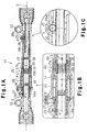
- Fig. 1A is a cross-sectional view of an electric power steering apparatus according to a first embodiment of the present invention;
- Figs. 1B and 1C are enlarged partial views showing the power steering apparatus of Fig. 1;
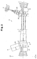
- Fig. 2 is a front view showing the power steering apparatus of Fig. 1;
- Fig. 3 is a cross-sectional view of a reduction mechanism in the power steering apparatus taken along line 3-3 in Fig. 2;
- Fig. 4 is an enlarged partial view showing the reduction mechanism of Fig. 3;
- Fig. 5 is an outer view showing a power steering apparatus according to a second embodiment of the present invention;
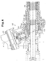
- Fig. 6 is a cross-sectional view of the main part of the power steering apparatus shown in Fig. 5;
- Fig. 7 is an enlarged view of Fig. 6;
- Fig. 8 is a plan view showing an electric power steering apparatus according to a third embodiment of the present invention;
- Fig. 9 is a cross-sectional view of the electric power steering apparatus shown in Fig. 8;
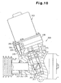
- Fig. 10 is a cross-sectional view showing the main part of Fig. 8;
- Fig. 11 is a diagram showing a modification of Fig. 10; and
- Fig. 12 is a cross-sectional view of an elastic member.
-
- An electric
power steering apparatus 11 according to a first embodiment of the present invention will be described below. - As shown in Fig. 1A, the electric
power steering apparatus 11 includes ahollow rack housing 13 which is provided with twoattachments 12, each formed on one of the two ends of thesteering apparatus 11. Thepower steering apparatus 11 is attached to a vehicle body (not shown) by fixing theattachments 12 to the vehicle body with screws. - As shown in Fig. 1B, the
rack housing 13 supports a nut-retainingsleeve 16 with first andsecond bearings sleeve 16 is enabled but longitudinal movement of the nut-retainingsleeve 16 is disabled. The nut-retainingsleeve 16 has a large-diameter portion on the end near the center S of therack housing 13 in the longitudinal direction of therack housing 13. Anut 17 is fitted into the large-diameter portion. - A female thread is formed at the end of the large-diameter portion, and a
lock screw 22 is engaged with the female thread. Thenut 17 is pressed against a stepped portion of the large-diameter portion by thelock screw 22. The nut-retainingsleeve 16 and thenut 17 define aball screw nut 20. The ball screwnut 20 covers part of arack shaft 18. - A
first ball groove 17a is formed helically in the inner circumferential surface of thenut 17. Asecond ball groove 18a is formed helically in therack shaft 18 for a predetermined length in the longitudinal direction of therack shaft 18. In the state shown in Fig. 1A, thefirst ball groove 17a faces thesecond ball groove 18a at the central region of thesecond ball groove 18a. A plurality ofballs 19 are received between thefirst ball groove 17a and thesecond ball groove 18a in a manner that rolling of theballs 19 is enabled. The ball screwnut 20, thesecond ball groove 18a, and theballs 19 define aball screw mechanism 21. - Due to the
ball screw mechanism 21, the rotation of therack shaft 18 with respect to therack housing 13 is disabled but the axial movement of therack shaft 18 is enabled. The two ends of therack shaft 18 are respectively connected to left and right front wheels (not shown) by tie rods (not shown). In Fig. 1A, rackteeth 18b are formed in therack shaft 18 at the right of the center S. - As shown in Fig. 2, a
pinion shaft sleeve 26 is provided at the right of the center S of therack housing 13, preferably in the vicinity of the right end of therack housing 13. Apinion shaft 25 is rotatably disposed in thepinion shaft sleeve 26. Thus, thepinion shaft 25 is arranged near the end of therack housing 13. - With reference to Fig. 2, the rotation of a steering wheel H rotates the
pinion shaft 25. The axis P of thepinion shaft 25 is inclined at an angle 1 with respect to the axis O of the rack housing 13 (the rack shaft 18). In the first embodiment, the angle 1 is about 70 degrees. - As shown in Fig. 1, a
pinion gear 25a, which meshes with therack teeth 18b, is formed on the basal end of thepinion shaft 25. Therack teeth 18b and thepinion gear 25a define a rack-and-pinion mechanism. Rotation of the steering wheel H rotates thepinion shaft 25 and thepinion gear 25a and moves therack shaft 18 having therack teeth 18b along the axis O. Movement of therack shaft 18 changes the steering angle of the front wheels (not shown). - As shown in Fig. 2, a
motor sleeve 27 used for attaching amotor 28 is provided at a position on the left of the center S of therack housing 13, preferably in the vicinity of the left end of therack housing 13. Accordingly, themotor 28 is arranged so as to face thepinion shaft sleeve 26 across the center S of therack housing 13. As shown in Fig. 3, arotating shaft 28a of themotor 28 is inserted in themotor sleeve 27. The axis M of the motor 28 (rotatingshaft 28a) is inclined at an angle 2 with respect to the axis O of therack shaft 18. In the first embodiment, the angle 2 is about 70 degrees. - A
first screw gear 29, or a drive gear, is connected to the distal end of therotating shaft 28a. Thefirst screw gear 29 is rotatably supported by third andfourth bearings 30 and 31, which are fixed to themotor sleeve 27. As shown in Fig. 1B, asecond screw gear 16a, or a driven gear, which meshes with thefirst screw gear 29, is formed on the outer circumferential surface of the nut-retainingsleeve 16 near the left end of the nut-retainingsleeve 16. Thefirst screw gear 29 is coaxial with therotating shaft 28a. Thefirst screw gear 29 is in contact with thesecond screw gear 16a inclined at an angle of about 70 degrees. Thefirst screw gear 29 and thesecond screw gear 16a define a reduction mechanism G (screw gear mechanism). - A reference line T, which extends through the center S of the
rack housing 13 and which is perpendicular to the axis O is shown in Fig. 2. In the state in which thepinion shaft 25 and themotor 28 are connected to therack housing 13, the axis P and the axis M are symmetric to each other about the reference line T. Thepinion shaft 25 and themotor 28 are arranged on the same plane. Both the angle between the axis P and the reference line T and the angle between the axis M and the reference line T are about 20 degrees. Accordingly, the distance between themotor 28 and thepinion shaft 25 increases as the height from therack housing 13 increases. - The
rotating shaft 28a of themotor 28 rotates in both forward and reverse directions. The driving force of themotor 28 is transmitted to the nut-retainingsleeve 16 via thefirst screw gear 29 and thesecond screw gear 16a. Theball screw mechanism 21 converts the rotational torque of the nut-retainingsleeve 16 into an assist force for the reciprocating movement of therack shaft 18 along the axis O. Due to this assist force, the steering force applied to the steering wheel H is reduced. - The
power steering apparatus 11 according to the first embodiment has the advantages described below. - (1) In the reduction mechanism of the first prior art,
the axes of the two spur gears can only be arranged parallel
to each other. In the reduction mechanism of the second
prior art, the axis of the worm and the axis of the worm
wheel can only be arranged perpendicular to each other. In
comparison, in the first embodiment, the reduction mechanism
G is the screw gear mechanism including the
first screw gear 29 and thesecond screw gear 16a. In the screw gear mechanism, the angle 1 between the axis of thefirst screw gear 29 and the axis of thesecond screw gear 16a are set arbitrarily by adjusting the direction of the tooth trace and the helix angle. In other words, there is a greater freedom for setting the installation angle of themotor 28 with respect to therack shaft 18 and theball screw mechanism 21 compared to the prior arts. Therefore, the electricpower steering apparatus 11 facilitates the arrangement of other devices of the vehicle (the engine, the transmission, etc.) around therack shaft 18. - (2) Fig. 4 is an enlarged view showing the meshing of
the
first screw gear 29 and thesecond screw gear 16a. Due to errors in assembly and dimensional accuracy of components in the electricpower steering apparatus 11, thefirst screw gear 29 may be displaced. Since the reduction mechanism G is the screw gear mechanism, even when thefirst screw gear 29 is displaced to a position shown by the two-dot chain lines, the meshing of thefirst screw gear 29 with thesecond screw gear 16a is ensured. In the first embodiment, the influence of errors in components and installation errors is small. - (3) In the reduction mechanism G, the reduction ratio
(the ratio of the number of teeth of the
first screw gear 29 to the number of teeth of thesecond screw gear 16a) may easily be changed. By adjusting the reduction ratio, a compact and light motor with a low output torque may be used. This facilitates the installation of other devices. Since compact and light motors with a small output torque are relatively inexpensive, the electricpower steering apparatus 11 is inexpensive. - (4) The
ball screw mechanism 21 of the first embodiment includes theball screw nut 20 having thefirst ball groove 17a, thesecond ball groove 18a provided in the outer circumference of therack shaft 18, and theballs 19 arranged between thefirst ball groove 17a and thesecond ball groove 18a. Thesecond screw gear 16a is provided on the outer circumference of theball screw nut 20.
Therefore, when themotor 28 and thefirst screw gear 29 rotate, thesecond screw gear 16a and theball screw nut 20 rotate accordingly. The rotation of theball screw nut 20 is converted into the axial movement of therack shaft 18 with the assistance of theballs 19. Accordingly, since thesecond screw gear 16a is provided on the outer circumference of theball screw nut 20, the driving force of themotor 28 is directly transmitted to theballs 19 via thesecond screw gear 16a and theball screw nut 20 without loss. - (5) The
second screw gear 16a is formed directly on the outer circumferential surface of the ball screw nut 20 (nut-retaining sleeve 16). Accordingly, in comparison to when thesecond screw gear 16a is formed separately from theball screw nut 20, the number of components of the electricpower steering apparatus 11 is reduced. In addition, it is not necessary to fix a separately formedsecond screw gear 16a to theball screw nut 20. - (6) In the electric power steering apparatuses of the
first and third prior arts, the motor is arranged at the
center of the rack shaft. Accordingly, it is necessary to
arrange the engine, the transmission, etc. such that they do
not interfere with the motor. In comparison, in the first
embodiment, the
motor 28 is arranged near an end of therack housing 13 and not in the vicinity of the center S of therack housing 13. Accordingly, in the vehicle including the electricpower steering apparatus 11, the arrangement of the engine, the transmission, etc. is facilitated. - (7) The
motor 28 and thepinion shaft 25 are respectively arranged at the two ends of therack housing 13. Accordingly, a relatively large space is provided around the central region of the electricpower steering apparatus 11. - (8) The axis P of the
pinion shaft 25 and the axis M of themotor 28 are symmetric to each other about the reference line T, which extends through the center S of therack housing 13 perpendicular to the axis O. In other words, the distance from the reference line T to the axis P of thepinion shaft 25 is the same as that from the reference line T to the axis M of themotor 28. Accordingly, the electricpower steering apparatus 11 has a superior balance of volume and weight. - (9) When the reduction mechanism includes a worm and a
worm wheel, the reduction ratio must be greater than about
1/10. However, since the reduction mechanism G of the first
embodiment includes the
first screw gear 29 and thesecond screw gear 16a, the reduction ratio of the reduction mechanism G may be set to a value that is less than that of the worm gear mechanism and thus has a wide setting range. - (10) In the first embodiment, the distance between the
motor 28 and thepinion shaft 25 increases as the height from therack housing 13 increases. Accordingly, compared to when the distance between the motor and the pinion shaft decreases as the height from the housing increases or when the motor and the pinion shaft are perpendicular to the rack housing, the engine, the transmission, etc. are easily arranged above therack housing 13 in the vehicle including the electricpower steering apparatus 11 of the first embodiment. -
- The first embodiment may also be modified as follows.
- The angle 2 between the axis M of the
motor 28 and the axis O of therack shaft 18 is not limited to about 70 degrees. As the angle 2 increases, that is, as the upper end of themotor 28 is positioned further away from the center, the space available for installing the engine, the transmission, etc. increases. - The axis P and the axis M do not have to lie along the same plane. For example, the axis M may be rotated by a predetermined angle (for example, 90 degrees) with respect to the axis O. In such a case, it is preferred that the position of the
motor sleeve 27 be changed. Themotor 28 and thepinion shaft 25 may be arranged with a relatively large degree of freedom in accordance with the other devices that are installed in the vehicle. - The
second screw gear 16a may be formed separately from the nut-retainingsleeve 16 and attached to the nut-retainingsleeve 16. - An electric power steering apparatus 100 according to a second embodiment of the present invention will now be described. As shown in Fig. 5, the power steering apparatus 100 includes a
steering gear mechanism 109, which is formed based on a rack-and-pinion gear mechanism, and a power-assist unit 105, which has anelectric motor 103. Thesteering gear mechanism 109 includes arack shaft 106 and apinion gear 191, which is connected to a steering shaft (not shown). Aball screw mechanism 166 is formed between therack shaft 106 and aball nut 162. - As shown in Fig. 6, the power-
assist unit 105 includes a transmission mechanism (reduction mechanism) 101 for transmitting the power of themotor 103 to therack shaft 106. Thetransmission mechanism 101 is a bevel gear mechanism including a drivenbevel gear 161, which integrally retains theball nut 162 with a retainer by means of a key 169, and adrive bevel gear 111, which meshes with the drivenbevel gear 161. Themotor 103 is connected to the rotating shaft of thedrive bevel gear 111 by acoupling 102. - The
transmission mechanism 101 of the second embodiment is an angular bevel gear mechanism in which the rotational axis of themotor 103 intersects the center axis of therack shaft 106 at a predetermined angle, which excludes a right angle. However, thetransmission mechanism 101 may also be a miter gear mechanism in which the intersection angle is 90 degrees. In addition, the drivenbevel gear 161 may also be formed integrally with theball nut 162. - In the power steering apparatus 100 of the second embodiment, the
steering gear mechanism 109 and the power-assist unit 105 are arranged at different positions. More specifically, thepinion gear 191 and the power-assist unit 105 are separated from each other along the axis of therack shaft 106 and lie along the same plane in a generally symmetric manner. Since the power-assist unit 105 is separated from thepinion gear 191, the power steering apparatus 100 is well-balanced. In addition, the structure around thepinion gear 191, where various components related to thesteering gear mechanism 109 are arranged in a concentrated manner, is simplified. This enables the space around thesteering gear mechanism 109 to be used effectively. In addition, when the installation position of the steering wheel is changed between left and right in accordance with where the vehicle is shipped to or for other reasons, the necessary changes in the power steering apparatus 100 can be made quickly. - Next, the power-
assist unit 105 will be described. As shown in Figs. 6 and 7, the rotating shaft of themotor 103 is connected to the relatively compactdrive bevel gear 111 by thecoupling 102, which may be an Oldham coupling. Thedrive bevel gear 111 meshes with the drivenbevel gear 161. The drivenbevel gear 161 is connected to theball nut 162 by means of the key 169, and theball nut 162 is connected to therack shaft 106 by means of theball screw mechanism 166. Accordingly, the drivenbevel gear 161, theball nut 162, and therack shaft 106 are coaxial. - As shown in Fig. 7, the driven
bevel gear 161 includes aring portion 611 having teeth and a boss portion 612, contacts the key 169. Adamper 615 composed of an elastic material such as rubber is arranged between thering portion 611 and the boss portion 612. Thecylindrical damper 615 is press-fitted between thering portion 611 and the boss portion 612, or is formed by adhering an elastic body through vulcanization. Thedamper 615 serves to reduce the rattling noise generated by thebevel gears rack shaft 106 or around the bevel gear mechanism due to, for example, reverse input from the steered wheels. - As shown in Fig. 7, a
collar 115 is attached to the shaft of thedrive bevel gear 111, and acollar 165 is arranged adjacent to the drivenbevel gear 161. The thicknesses of thecollars rack shaft 106 and the backlash between thebevel gears prepared collars collars - The power steering apparatus 100 of the second embodiment has the advantages described below.
- (11) Since the
transmission mechanism 101 includes the angular bevel gear mechanism and backlash adjustment or the like is performed relatively easily using thecollars 115 and 116, the power steering apparatus 100 is suitable for mass production. - (12) Since the bevel gear mechanism can perform
reversible or two-way power transmission, even when the
motor 103 fails to function or stops functioning, the steering operation may be performed manually with thepinion gear 191 and the steering shaft. Accordingly, the power steering apparatus 100 has a fail-safe function. - (13) The rotational axis M of the
motor 103 intersects the axis O of therack shaft 106 at point X, and the axis M of themotor 103 and the axis O of therack shaft 106 lie on the same plane. That is, themotor 103 is installed such that themotor 103 is not offset from therack shaft 106. As a result, the space around the power-assist unit 105 is used effectively. - (14) Since the power-
assist unit 105 and thepinion gear 191 of thesteering gear mechanism 109 are arranged symmetrically to each other, many parts of the power steering apparatus 100 can be used in common for right-hand drive vehicles and left-hand drive vehicles. In addition, even when the vehicle must be converted, for example, from left-hand drive to right-hand drive in accordance with where the vehicle is shipped to, the necessary changes can be made quickly. - (15) In the electric power steering apparatus 100 of
the second embodiment, the
transmission mechanism 101 is formed by a bevel gear mechanism. Since the power transmission efficiency of the bevel gear mechanisms is significantly superior to that of worm wheel mechanisms, the power of themotor 103 is efficiently transmitted to therack shaft 106. As a result, a relatively compact motor may be used as themotor 103. In addition, although the distance between the axis of the worm and that of the wheel must be accurately maintained in worm wheel mechanisms, the restriction on the distance between the axes is relatively mild in bevel gear mechanisms. - (16) In the driven
bevel gear 161 attached to theball nut 162, thedamper 615 composed of a rubber-like elastic material is provided on the boss portion 612. Thedamper 615 reduces abnormal noise generated by the power-assist unit 105, for example, the rattling noise generated by the bevel gear mechanism, which forms thetransmission mechanism 101. In addition, when an impact force is applied in the axial direction of therack shaft 106 or around the bevel gear mechanism due to, for example, reverse input from the steered wheels, the impact force is reduced by thedamper 615. - (17) In the second embodiment, the driven
bevel gear 161 is integrated with theball nut 162, and theball nut 162 is arranged coaxially with therack shaft 106 by means of theball screw mechanism 166. Accordingly, the power (assist force) of themotor 103 is transmitted to therack shaft 106 via theball screw mechanism 166, the frictional resistance of which is low, and the assist force of themotor 103 is smoothly transmitted to thesteering gear mechanism 109. - (18) Since the
transmission mechanism 101 is an angular bevel gear mechanism, the angle between the central axis of thedrive bevel gear 111 and that of the drivenbevel gear 161 can be set to any angle except a right angle. Accordingly, the intersection angle between the axis M of themotor 103 connected to thetransmission mechanism 101 and the axis O of therack shaft 106 may be set with a large degree of freedom and other devices can be easily arranged around the electric power steering apparatus 100. -
- When the
transmission mechanism 101 includes a miter gear mechanism, the intersection angle between the central axes of the two gears is limited to a right angle. However, the advantages described above in items (11) to (17) are obtained. - Next, an electric power steering apparatus 200 according to a third embodiment of the present invention will be described.
- As shown in Fig. 8, the power steering apparatus 200 includes a rack-and-pinion
steering gear mechanism 209 and a power-assist unit 208 having anelectric motor 203. Thesteering gear mechanism 209 includes a steering shaft (not shown) and apinion gear 291, which is connected to arack shaft 206. - The
pinion gear 291 and the power-assist unit 208 are arranged at different positions. More specifically, thepinion gear 291 and the power-assist unit 208 are separated from each other along the axis of therack shaft 206 and lie along the same plane in a generally symmetric manner. Since the power-assist unit 208 is separated from thepinion gear 291, the power steering apparatus 200 is well-balanced. In addition, the structure around thepinion gear 291, where various components related to thesteering gear mechanism 209 are arranged in a concentrated manner, may be simplified. Thus, the space around thesteering gear mechanism 209 may be used effectively. In addition, when the installation position of the steering wheel is changed between the left and right due to a change in where the vehicle is shipped to or the like, the necessary changes in the power steering apparatus 200 may be made quickly. - As shown in Fig. 10, a
rotating shaft 231 of theelectric motor 203 is connected to arotating shaft 211 of a drive gear (small screw gear) 201 by acoupling 202. Thedrive gear 201 meshes with a driven gear (screw gear) 261, which is formed integrally with aball nut 262. Thedrive gear 201 and the drivengear 261 define a reduction mechanism. Acasing 235 of theelectric motor 203 is fixed to ahousing 215, which accommodates thesmall screw gear 201 and thecoupling 202, by means of anelastic member 205 having a predetermined thickness. - Next, the power-
assist unit 208 will be described below with reference to Fig. 10. As shown in Fig. 10, therotating shaft 231 of theelectric motor 203 is connected to therotating shaft 211 of thesmall screw gear 201 by theOldham coupling 202. Theelastic member 205, which has the predetermined thickness, is arranged between aflange 355 of thecasing 235, which accommodates theelectric motor 203, and aflange 245 of thehousing 215, which accommodates thesmall screw gear 201. Theflanges elastic member 205 is arranged between thehousing 215 and theelectric motor 203, there is a risk that the axis of therotating shaft 231 of theelectric motor 203 and that of therotating shaft 211 of thesmall screw gear 201 will be misaligned during operation of theelectric motor 203. TheOldham coupling 202 serves to absorb the influence of misalignment of the axes. - As shown in Fig. 11, a
flexible coupling 202a composed of metal may also be used in place of theOldham coupling 202. Theflexible coupling 202a is formed by a plurality of flexible metal rings (metal-ring aggregate) arranged between themotor rotating shaft 231 and therotating shaft 211 of thesmall screw gear 201. Since the metal rings can be inclined, although only slightly, with respect to one another, the entire body of theflexible coupling 202a may be deformed by a predetermined amount. Accordingly, even when the axis of themotor rotating shaft 231 and that of therotating shaft 211 of thesmall screw gear 201 are misaligned or tilted with respect to each other, theflexible coupling 202a can cope with such conditions. - Next, the connection between the
casing 235 and thehousing 215 will be described. As shown in Fig. 12, theelastic member 205, which has the predetermined thickness, is arranged between theflange 355 of thecasing 235 and theflange 245 of thehousing 215. Theelastic member 205 is in contact with the entire surfaces of theflanges elastic member 205 has a collar-receivinghole 511. Acollar 251 having an outer diameter that is substantially the same as the inner diameter of the collar-receivinghole 511 is fitted in the collar-receivinghole 511. Theflange 355 has a collar-receivinghole 356 having an inner diameter that is slightly larger than the outer diameter of thecollar 251. Thecollar 251 is inserted in the collar-receivinghole 356. The lower end of thecollar 251 is in contact with the upper surface of theflange 245. Thecollar 251 restricts the distance between theflanges flanged bolt 55 is inserted through thecollar 251 to fasten theflanges elastic member 205 is deformed, thecollar 251 and thebolt 55 tolerates tilting of thecasing 235. - Next, a buffer mechanism for reducing an impact applied at the ends of the steering stroke of the power steering apparatus 200 when the
rack shaft 206 reaches the ends of its stroke will be described. - The power steering apparatus 200 includes a buffer mechanism which prevents a ball joint 265 formed on each end of the
rack shaft 206 from hitting itsrespective stopper 257 of thehousing 215 and generating a metallic impact noise when therack shaft 206 reaches the ends of its stroke. As shown in Figs. 9 and 10, the buffer mechanism includes abuffer member 207, like a leaf spring or a belleville spring, which is adjacent to thestopper 257 formed on part of thehousing 215. When therack shaft 206 reaches the end of its stroke, thebuffer member 207 contacts the ball joint 265. Accordingly, thestopper 257 is prevented from hitting the ball joint 265 and generating vibration and noise. - The power steering apparatus 200 of the third embodiment has the advantages described below.
- (19) The
casing 235 is connected to thehousing 215 by means of theelastic member 205. The vibration and noise of theelectric motor 203 are blocked by theelastic member 205 and are not transmitted to the passenger compartment. - (20) The
rotating shaft 231 of theelectric motor 203 is connected to therotating shaft 211 of thesmall screw gear 201 by theOldham coupling 202 or theflexible coupling 202a. Accordingly, even when theelastic member 205 is deformed and the central axes of the twoshafts electric motor 203 is smoothly transmitted to thesmall screw gear 201 via thecoupling elastic member 205 are easily adjusted by selecting the proper thickness or hardness of theelastic member 205. - (21) The power-
assist unit 208 and thepinion gear 291 are arranged at different positions. More specifically, the power-assist unit 208 and thepinion gear 291 are arranged on the axis of therack shaft 206 at generally symmetric positions. Accordingly, the structure around thepinion gear 291, where various components related to thesteering gear mechanism 209 are arranged in a concentrated manner, is simplified, and the space around thesteering gear mechanism 209 may be used effectively. In addition, the adjustment of thegear mechanism 209 may be performed smoothly. - (22) The
buffer member 207 is adjacent to thestopper 257 of thehousing 215, which accommodates therack shaft 206. When therack shaft 206 reaches the end of its stroke, thebuffer member 207 contacts the ball joint 265 provided at each end of therack shaft 206 so that the ball joint 265 does not hit thestopper 257. This prevents the generation of vibration and noise. In addition, the ball nut 61 is prevented from being caught in theball screw mechanism 266. - (23) The power-
assist unit 208 may be arranged at any angle in a range of 360 degrees about the axis of therack shaft 206. Thus, the power-assist unit 208 may be installed with a large degree of freedom. - (24) Even when the central axes of the
shafts elastic member 205, the misalignment is tolerated since an Oldham coupling is used as thecoupling 202. -
- The
elastic member 205 may also be used in thepower steering apparatuses 11 and 100 of the first and second embodiments.
Claims (15)
- An electric power steering apparatus (11; 100; 200) for transmitting a driving force of a motor (28; 103; 203) to a rack shaft (18; 106; 206) via a reduction mechanism (G; 101; 201 and 261) and a ball screw mechanism (21) to assist movement of the rack shaft in a longitudinal axis (O) thereof, the electric power steering apparatus being characterized in that:the reduction mechanism includes a drive gear (29; 111; 201) connected to a rotating shaft (28a; 231) of the motor, and a driven gear (16a; 161; 261) meshed with the drive gear and connected to the ball screw mechanism, with the rotating shaft of the motor intersecting the longitudinal axis of the rack shaft at an arbitrary angle (2).
- The electric power steering apparatus according to claim 1, characterized in that the drive gear is a first screw gear, the driven gear is a second screw gear, and the reduction mechanism is a screw gear mechanism (101) including the first screw gear and the second screw gear.
- The electric power steering apparatus according to claim 1, characterized in that the drive gear is a first bevel gear (111), the driven gear is a second bevel gear (161), and the reduction mechanism is a bevel gear mechanism including the first bevel gear and the second bevel gear.
- The electric power steering apparatus according to claim 3, characterized in that each of the first bevel gear and the second bevel gear is an angular bevel gear, and the bevel gear mechanism is an angular bevel gear mechanism.
- The electric power steering apparatus according to any one of claims 1 to 4, characterized in that the ball screw mechanism includes a ball screw nut (20) having a helical first ball groove (17a) extending along its inner circumferential surface, a helical second ball groove (18a) extending along an outer circumferential surface of the rack shaft, and a plurality of balls (19) arranged between the helical first ball groove and the helical second ball groove, and the driven gear is provided on the outer circumferential surface of the ball screw nut.
- The electric power steering apparatus according to claim 5, characterized in that the driven gear is formed on the outer circumferential surface of the ball screw nut.
- The electric power steering apparatus according to claim 5, characterized in that the driven gear is connected to the ball screw nut by a damper (615), which is an elastic body.
- The electric power steering apparatus according to one of claims 1 to 4, characterized by:a coupling (202) arranged between the rotating shaft (231) of the motor and a rotating shaft (211) of the drive gear (201) to transmit the rotation of the rotating shaft (231) of the motor to the rotating shaft (211) of the drive gear, wherein the coupling tolerates axes misalignment of the rotating shaft (211) of the drive gear and the rotating shaft (231) of the motor;a casing (235) for accommodating the motor;a housing (215) for accommodating the drive gear; andan elastic member (205) having a predetermined thickness arranged between the casing and the housing, with the casing attached to the housing by means of the elastic member.
- The electric power steering apparatus according to claim 8, characterized in that the coupling is an Oldham coupling.
- The electric power steering apparatus according to any one of claims 1 to 4, further characterized by a rack housing (13) accommodating the rack shaft, wherein the motor is attached to the rack housing (13) in the vicinity of one of the ends of the rack housing (13).
- The electric power steering apparatus according to claim 10, further characterized by a pinion shaft (25) for transmitting a driving force of a steering wheel to the rack shaft, the pinion shaft including a pinion gear (25a) meshed with the rack teeth (18b) formed on the rack shaft, and the pinion shaft being arranged near the other one of the ends of the rack housing.
- The electric power steering apparatus according to claim 11, characterized in that the axis (M) of the motor and the axis (P) of the pinion shaft are symmetric to each other about a reference line (T) perpendicular to a longitudinal axis of the rack housing at the center (S) of the rack housing along the longitudinal axis.
- The electric power steering apparatus according to claim 12, characterized in that the motor and the pinion shaft become farther from the reference line (T) as the motor and the pinion shaft become farther from the rack housing.
- An electric power steering apparatus (11; 100; 200) characterized by:a rack shaft (18; 106; 206) having a longitudinal axis (O);a rack housing (16) for accommodating the rack shaft and having a first end and a second end;a pinion shaft (25) arranged in the vicinity of the first end of the rack housing and connected to the rack shaft;a motor (28; 103; 203) arranged in the vicinity of the second end of the rack housing;a ball nut (20; 162; 262) arranged coaxially to the rack shaft in a manner covering the rack shaft, wherein the ball nut is rotated relative to the rack shaft to move the rack shaft along the longitudinal axis; anda reduction mechanism (G; 101; 201 and 261) arranged between the motor and the ball nut to transmit rotation of a rotating shaft (28a) of the motor to the ball screw nut while reducing the speed of the rotation, wherein the reduction mechanism includes a drive gear (29; 101; 201) coaxially connected to the rotating shaft of the motor and a driven gear (16a; 161; 261) arranged on the outer surface of the ball screw nut and meshed with the drive gear, with the axis of the drive gear inclined with respect to the axis of the driven gear.
- The electric power steering apparatus according to claim 14, characterized in that the driven gear is connected to the ball nut by a damper (615) such that the driven gear is coaxial with the rack shaft.
Applications Claiming Priority (7)
| Application Number | Priority Date | Filing Date | Title |
|---|---|---|---|
| JP2001209371 | 2001-07-10 | ||
| JP2001209371A JP2003026007A (en) | 2001-07-10 | 2001-07-10 | Electric power steering device |
| JP2001213137 | 2001-07-13 | ||
| JP2001213137A JP2003026009A (en) | 2001-07-13 | 2001-07-13 | Electric power steering device |
| JP2001323070 | 2001-10-22 | ||
| JP2001323070A JP2003127879A (en) | 2001-10-22 | 2001-10-22 | Electric power steering device |
| PCT/JP2002/006907 WO2003006301A1 (en) | 2001-07-10 | 2002-07-08 | Electronic control power steering device |
Publications (2)
| Publication Number | Publication Date |
|---|---|
| EP1405781A1 true EP1405781A1 (en) | 2004-04-07 |
| EP1405781A4 EP1405781A4 (en) | 2006-11-02 |
Family
ID=27347129
Family Applications (1)
| Application Number | Title | Priority Date | Filing Date |
|---|---|---|---|
| EP02743852A Withdrawn EP1405781A4 (en) | 2001-07-10 | 2002-07-08 | Electronic control power steering device |
Country Status (3)
| Country | Link |
|---|---|
| US (1) | US6973990B2 (en) |
| EP (1) | EP1405781A4 (en) |
| WO (1) | WO2003006301A1 (en) |
Cited By (2)
| Publication number | Priority date | Publication date | Assignee | Title |
|---|---|---|---|---|
| DE102008000210A1 (en) * | 2008-02-01 | 2009-08-06 | Zf Lenksysteme Gmbh | Electrical power steering system i.e. power steering mechanism, for vehicle i.e. passenger car, has pinion, where axial distance of pinion in nut corresponds to double stroke of axially movable component |
| DE102014008329A1 (en) * | 2014-06-12 | 2015-12-17 | Siemens Aktiengesellschaft | Gear for converting a rotational movement into a linear movement |
Families Citing this family (20)
| Publication number | Priority date | Publication date | Assignee | Title |
|---|---|---|---|---|
| JP4436031B2 (en) * | 2002-05-31 | 2010-03-24 | 日産自動車株式会社 | Vehicle steering control device |
| JP4013132B2 (en) | 2002-09-30 | 2007-11-28 | 株式会社ジェイテクト | Electric power steering device |
| JP2004314854A (en) * | 2003-04-17 | 2004-11-11 | Koyo Seiko Co Ltd | Steering device for vehicle |
| JP2005007969A (en) * | 2003-06-17 | 2005-01-13 | Koyo Seiko Co Ltd | Power steering apparatus |
| JP2005075117A (en) * | 2003-08-29 | 2005-03-24 | Favess Co Ltd | Electric power steering device |
| US20060060413A1 (en) * | 2004-09-17 | 2006-03-23 | Mando Corporation | Rack type power steering apparatus |
| JP4726522B2 (en) * | 2005-03-31 | 2011-07-20 | 本田技研工業株式会社 | Mounting structure of electric power steering device for vehicle |
| US20090260468A1 (en) * | 2005-08-31 | 2009-10-22 | Thk Co., Ltd. | Steering device and movement converting device used therefor |
| JP5120040B2 (en) * | 2008-04-14 | 2013-01-16 | 株式会社ジェイテクト | Ball screw device and electric power steering device using the same |
| US8307940B2 (en) * | 2010-03-15 | 2012-11-13 | Trw Automotive U.S. Llc | Electric power steering assembly |
| JP5811397B2 (en) * | 2010-10-21 | 2015-11-11 | 株式会社ジェイテクト | Vehicle steering system |
| DE102011003562A1 (en) * | 2011-02-03 | 2012-08-09 | Ford Global Technologies, Llc | Ball screw and thus equipped steering device |
| JP5801232B2 (en) * | 2012-03-22 | 2015-10-28 | 日立オートモティブシステムズステアリング株式会社 | Power steering device and housing for electric power steering device |
| DE102013223380A1 (en) * | 2013-01-10 | 2014-07-10 | Ford Global Technologies, Llc | Electric power steering for vehicles |
| KR101560980B1 (en) * | 2014-06-23 | 2015-10-15 | 주식회사 만도 | Power Transmission Device of Electric Power Steering Apparatus |
| KR102427344B1 (en) * | 2018-10-26 | 2022-07-29 | 현대모비스 주식회사 | Steering device for vehicle |
| CN111766406B (en) * | 2020-07-01 | 2024-02-09 | 合肥兆科机电科技有限公司 | Concentric circle three-dimensional electric step-by-step scanning system for high-vacuum scientific experimental device |
| CN113090681B (en) * | 2021-04-08 | 2022-12-30 | 中国第一汽车股份有限公司 | Clutch actuating mechanism and vehicle |
| US20230142494A1 (en) * | 2021-11-08 | 2023-05-11 | Zf Active Safety And Electronics Us Llc | Apparatus for use in turning steerable vehicle wheels |
| CN114810936B (en) * | 2022-06-13 | 2023-06-09 | 国网安徽省电力有限公司经济技术研究院 | Monitoring device for medium-low voltage power distribution system |
Family Cites Families (28)
| Publication number | Priority date | Publication date | Assignee | Title |
|---|---|---|---|---|
| JPS6025853A (en) | 1983-07-22 | 1985-02-08 | Nippon Seiko Kk | Electrical power steering device |
| JPS60151774U (en) * | 1984-03-21 | 1985-10-08 | 富士重工業株式会社 | Steering gear box structure of electric power steering device |
| JPS60164471U (en) * | 1984-04-10 | 1985-10-31 | 富士重工業株式会社 | Steering gear box structure of electric power steering device |
| JPH0688537B2 (en) * | 1984-09-27 | 1994-11-09 | 本田技研工業株式会社 | Electric power steering device |
| JPH0249106Y2 (en) * | 1985-03-22 | 1990-12-25 | ||
| JPH0624953B2 (en) * | 1986-04-08 | 1994-04-06 | 本田技研工業株式会社 | Electric power steering device |
| JPH0662092B2 (en) * | 1986-04-11 | 1994-08-17 | 本田技研工業株式会社 | Electric power steering device |
| JPH05472Y2 (en) * | 1986-10-09 | 1993-01-07 | ||
| JPH0644674A (en) | 1992-05-26 | 1994-02-18 | Fujitsu Ltd | Disk storage |
| JPH0899643A (en) | 1994-09-28 | 1996-04-16 | Koyo Seiko Co Ltd | Power steering |
| JP3779743B2 (en) * | 1995-02-06 | 2006-05-31 | 日本精工株式会社 | Electric power steering device |
| JPH0966844A (en) * | 1995-09-04 | 1997-03-11 | Nippon Seiko Kk | Electric power steering device |
| JPH09123927A (en) * | 1995-11-02 | 1997-05-13 | Nippon Seiko Kk | Electric power steering device |
| US6338285B2 (en) * | 1996-06-17 | 2002-01-15 | Nsk Ltd. | Feed screw device |
| JP3802649B2 (en) * | 1997-05-12 | 2006-07-26 | 本田技研工業株式会社 | Cable-type steering device |
| JP2000095123A (en) | 1998-09-24 | 2000-04-04 | Showa Corp | Method of assembling ball screw in electric power steering device |
| US6164407A (en) * | 1998-12-04 | 2000-12-26 | Trw Inc. | Electric power steering apparatus |
| US6155376A (en) * | 1998-12-28 | 2000-12-05 | Trw Inc. | Electric power steering assembly |
| JP2000280923A (en) * | 1999-04-01 | 2000-10-10 | Showa Corp | Electric power steering device |
| JP4056172B2 (en) * | 1999-04-01 | 2008-03-05 | 株式会社ショーワ | Electric power steering device |
| JP2000350397A (en) | 1999-05-31 | 2000-12-15 | Mitsubishi Electric Corp | Motor for electric power steering system |
| US6749040B1 (en) * | 1999-09-01 | 2004-06-15 | Delphi Technologies, Inc. | Electric power assisted rack and pinion system |
| JP3822003B2 (en) * | 1999-09-29 | 2006-09-13 | 株式会社ジェイテクト | Electric power steering device |
| US6390230B1 (en) * | 1999-10-06 | 2002-05-21 | Honda Giken Kogyo Kabushiki Kaisha | Electric power steering apparatus |
| JP3829045B2 (en) * | 2000-05-11 | 2006-10-04 | 株式会社ジェイテクト | Electric power steering device |
| JP4524880B2 (en) * | 2000-08-10 | 2010-08-18 | マツダ株式会社 | Electric power steering device for automobile |
| KR20020062569A (en) * | 2001-01-22 | 2002-07-26 | 고요 세이코 가부시키가이샤 | An electric power steering system |
| US6454044B1 (en) * | 2001-04-17 | 2002-09-24 | Delphi Technologies, Inc. | Gearing without backlash for electric power steering |
-
2002
- 2002-07-08 EP EP02743852A patent/EP1405781A4/en not_active Withdrawn
- 2002-07-08 WO PCT/JP2002/006907 patent/WO2003006301A1/en not_active Ceased
- 2002-07-08 US US10/483,248 patent/US6973990B2/en not_active Expired - Fee Related
Non-Patent Citations (2)
| Title |
|---|
| No further relevant documents disclosed * |
| See also references of WO03006301A1 * |
Cited By (2)
| Publication number | Priority date | Publication date | Assignee | Title |
|---|---|---|---|---|
| DE102008000210A1 (en) * | 2008-02-01 | 2009-08-06 | Zf Lenksysteme Gmbh | Electrical power steering system i.e. power steering mechanism, for vehicle i.e. passenger car, has pinion, where axial distance of pinion in nut corresponds to double stroke of axially movable component |
| DE102014008329A1 (en) * | 2014-06-12 | 2015-12-17 | Siemens Aktiengesellschaft | Gear for converting a rotational movement into a linear movement |
Also Published As
| Publication number | Publication date |
|---|---|
| US6973990B2 (en) | 2005-12-13 |
| EP1405781A4 (en) | 2006-11-02 |
| US20040168849A1 (en) | 2004-09-02 |
| WO2003006301A1 (en) | 2003-01-23 |
Similar Documents
| Publication | Publication Date | Title |
|---|---|---|
| US6973990B2 (en) | Electronic control power steering device | |
| US6705176B2 (en) | Electric power steering apparatus | |
| EP1065132B1 (en) | Electric power steering apparatus | |
| US7278334B2 (en) | Electric power steering apparatus | |
| US8272473B2 (en) | Active steering control system | |
| US5213173A (en) | Electric power steering apparatus | |
| US10883594B2 (en) | Worm reducer | |
| CN113044111A (en) | Electric power steering gear for automobile | |
| EP1777140A1 (en) | Tensioner for belt-type transmission and electric power steering apparatus having the same | |
| JP2000280920A (en) | Electric power steering device | |
| JP2001322554A (en) | Electric power steering device | |
| EP1813507B1 (en) | Electric power steering apparatus | |
| JPH1134888A (en) | Electric power steering device | |
| US8336412B1 (en) | Electric power steering apparatus | |
| US12448031B2 (en) | Electric power steering system reducer and electric power steering system | |
| EP2662265A1 (en) | Steering device | |
| CN214648540U (en) | Electric power steering gear for automobile | |
| US20060060414A1 (en) | Electric power steering system | |
| JP4352325B2 (en) | Electric power steering device | |
| US6953103B2 (en) | Method for installing flexibly coupled electric power assist steering system | |
| JP2002340017A (en) | Joint mechanism, and steering operation assisting device using the same | |
| JP3613696B2 (en) | Electric power steering device | |
| JP4400195B2 (en) | Vehicle steering system | |
| JPH04123875U (en) | Electric power steering device | |
| JPH045168A (en) | Motor-driven power steering |
Legal Events
| Date | Code | Title | Description |
|---|---|---|---|
| PUAI | Public reference made under article 153(3) epc to a published international application that has entered the european phase |
Free format text: ORIGINAL CODE: 0009012 |
|
| 17P | Request for examination filed |
Effective date: 20040108 |
|
| AK | Designated contracting states |
Kind code of ref document: A1 Designated state(s): AT BE BG CH CY CZ DE DK EE ES FI FR GB GR IE IT LI LU MC NL PT SE SK TR |
|
| RAP1 | Party data changed (applicant data changed or rights of an application transferred) |
Owner name: JTEKT CORPORATION |
|
| A4 | Supplementary search report drawn up and despatched |
Effective date: 20061004 |
|
| RIN1 | Information on inventor provided before grant (corrected) |
Inventor name: UKAI, FUMIOJTEKT CORPORATION Inventor name: INAGUMA, YOSHIHARUJTEKT CORPORATION Inventor name: KAWABATA, NOBUYUKIJTEKT CORPORATION Inventor name: KOBAYASHI, TSUNEJTEKT CORPORATION Inventor name: HONAGA, SUSUMUJTEKT CORPORATION |
|
| 17Q | First examination report despatched |
Effective date: 20071001 |
|
| STAA | Information on the status of an ep patent application or granted ep patent |
Free format text: STATUS: THE APPLICATION IS DEEMED TO BE WITHDRAWN |
|
| 18D | Application deemed to be withdrawn |
Effective date: 20080211 |