EP1404571B1 - Durch aktive kontrolle auslösbares ballastsystem für taucher - Google Patents
Durch aktive kontrolle auslösbares ballastsystem für taucher Download PDFInfo
- Publication number
- EP1404571B1 EP1404571B1 EP01955992A EP01955992A EP1404571B1 EP 1404571 B1 EP1404571 B1 EP 1404571B1 EP 01955992 A EP01955992 A EP 01955992A EP 01955992 A EP01955992 A EP 01955992A EP 1404571 B1 EP1404571 B1 EP 1404571B1
- Authority
- EP
- European Patent Office
- Prior art keywords
- ballast
- active control
- attached
- strap
- Prior art date
- Legal status (The legal status is an assumption and is not a legal conclusion. Google has not performed a legal analysis and makes no representation as to the accuracy of the status listed.)
- Expired - Lifetime
Links
- 238000003780 insertion Methods 0.000 claims description 19
- 230000037431 insertion Effects 0.000 claims description 18
- XLYOFNOQVPJJNP-UHFFFAOYSA-N water Substances O XLYOFNOQVPJJNP-UHFFFAOYSA-N 0.000 abstract description 7
- 230000007246 mechanism Effects 0.000 description 15
- 238000013461 design Methods 0.000 description 12
- 230000004913 activation Effects 0.000 description 5
- 239000000463 material Substances 0.000 description 4
- 238000012549 training Methods 0.000 description 4
- 230000009471 action Effects 0.000 description 3
- 230000009189 diving Effects 0.000 description 3
- 239000004744 fabric Substances 0.000 description 3
- 238000000034 method Methods 0.000 description 3
- 230000003247 decreasing effect Effects 0.000 description 2
- 230000009977 dual effect Effects 0.000 description 2
- 238000005188 flotation Methods 0.000 description 2
- 230000000717 retained effect Effects 0.000 description 2
- 230000008859 change Effects 0.000 description 1
- 230000006872 improvement Effects 0.000 description 1
- 230000005764 inhibitory process Effects 0.000 description 1
- 230000002452 interceptive effect Effects 0.000 description 1
- 230000013011 mating Effects 0.000 description 1
- 229910052751 metal Inorganic materials 0.000 description 1
- 239000002184 metal Substances 0.000 description 1
- 150000002739 metals Chemical class 0.000 description 1
- 238000012986 modification Methods 0.000 description 1
- 230000004048 modification Effects 0.000 description 1
- 230000007935 neutral effect Effects 0.000 description 1
- 239000004576 sand Substances 0.000 description 1
- 238000000926 separation method Methods 0.000 description 1
- 238000009958 sewing Methods 0.000 description 1
- 230000000007 visual effect Effects 0.000 description 1
Images


Classifications
-
- B—PERFORMING OPERATIONS; TRANSPORTING
- B63—SHIPS OR OTHER WATERBORNE VESSELS; RELATED EQUIPMENT
- B63C—LAUNCHING, HAULING-OUT, OR DRY-DOCKING OF VESSELS; LIFE-SAVING IN WATER; EQUIPMENT FOR DWELLING OR WORKING UNDER WATER; MEANS FOR SALVAGING OR SEARCHING FOR UNDERWATER OBJECTS
- B63C11/00—Equipment for dwelling or working underwater; Means for searching for underwater objects
- B63C11/02—Divers' equipment
- B63C11/30—Ballast
Definitions
- the present invention relates generally to weight systems for dive equipment and more particularly to an active control releasable ballast system for use with dive equipment such as, but not limited to, dive belts, buoyancy compensators and diver harnesses.
- hook and loop fasteners include: (1) it can become fowled in a single outing without positive warning, and (2) it is far too variable to adequately accommodate the wide range of holding strengths required by the diverse set of ballast requirements inherent to diving (i.e. one diver may need two pounds per side whereas the next diver may need twenty pounds). This large volume of hook and loop needed has made weight release very challenging to deploy and expensive to produce.
- US 5944450 discloses a buoyancy compensator for a scuba diver vest having a pocket on each side of the front of the vest, a weight module removably positioned in each pocket, each weight module includes an envelope releasably mounted in said pocket a weight packet carried within the envelope, a weight removably mounted in said envelope, a strap operatively connected to the envelope and releasably connected to the vest The weight is dropped from the weight packet by pulling the weight packet from the pocket and the envelope is returned to the pocket by a pair of elastic bands.
- an active control releasable ballast integrated weight system for use with dive equipment, such as, but not limited to, dive belts, buoyancy compensators, diver harnesses, life jackets, life vests, etc.
- the system preferably includes an exterior or fixed pocket, a removable ballast member pocket, a ballast member disposed within the removable pocket, a first strap attached to the exterior pocket, a second strap attached to or proximate the exterior pocket, a male insertion member attached to a first strap, and a female receiving member attached to the second strap.
- the male insertion member and female receiving member combine to form a side release buckle.
- the system can be incorporated integral or permanently attached to the dive equipment or can be removably attached to the dive equipment.
- a handle member can be attached to the removable pocket 54, preferably through a strap member.
- a flap can be provided integral with the removable pocket. The ballast member is disposed within the removable pocket and retained therein when the flap is in a closed position.
- the side release buckle provides a single point active fastening device (which is attached solely to the fixed pocket) and handle (which is attached to the removable ballast member pocket).
- the design specifically secures the weight member in place and allows the second strap to pass over the leading edge of the removable ballast pocket, which is internally disposed within the fixed pocket.
- a first rigid plate can be incorporated within the exterior pocket and a second rigid plate can be provided within the removable pocket.
- the plates are preferably shaped such that they are slightly curved and/or form a relatively small angle at approximately their halfway points.
- the curvature of the first rigid plate helps to conform the associated dive equipment with the user's body, by making the equipment choose a position on the user's body.
- the curvature of the second rigid plate helps for inserting the ballast member in a more natural and easily articulated motion.
- separate handle 66 is eliminated by attaching the strap and either the male insertion member or the female insertion member to the removable pocket.
- a strap with a buckle section or handle can also be attached directly to the ballast member.
- the side release buckle secures the weight pocket and at the same time acts as the primary method of holding the releasable ballast component pre-insertion and post removal when weight handling is critical to the following: (1) Unanticipated ballast loss can be fatal due to the rate of ascent produced by natural and applied buoyant devices no-longer being countered.
- the conventional use of hook and loop fasteners for this application was originally introduced in the spirit of keeping with the "single hand or quick release" habits taught since the inception of recreational scuba dive training agencies; and (2) Control of the ballast generally requires a handle for a secure grip as lead is generally used as ballast and can be extremely difficult to manage compared to its relatively small size.
- the strategic location of the side release buckle at a point that is comfortable for the user's hand to articulate and the user's eye creates a single point release and handle control of the ballast member in a diver integrated weight system for a BC, dive belt, harness, or other dive equipment.
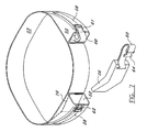
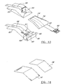
- system 50 preferably includes an exterior or fixed pocket 52 (best seen in Figure 8), ballast member pocket 54, ballast member 56 disposed within pocket 54, first strap 58 attached to exterior pocket 52, second strap 60 attached to or approximate pocket 52, a male insertion member 62 attached to either first strap 58 or second strap 60, and a female receiving member 64 attached to either second strap 60 or first strap 58 (the opposite strap to which male insertion member 62 is attached to).
- male insertion member 62 and female receiving member 64 combine to form a side release buckle generally designated as buckle 61.
- Active control ballast system 50 can be provided or used with a dive belt 53, buoyancy compensator 51, life vest, life jacket, diver harness, etc. ("dive equipment”) and all are considered within the scope of the invention.
- System 50, as well as all embodiments of the present invention, can be incorporated integral or permanently attached to the dive equipment or can be removably attached to the dive equipment (See Figures 5, 6 and 10).
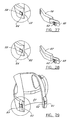
- a handle member 66 (66a in Figure 1 or 66b in Figure 8)can be attached to pocket 54, preferably through a strap member 68.
- a flap 70 can be provided integral with pocket 54.
- a means for maintaining flap 70 in a closed position with respect to pocket 54 can also be provided.
- the means for maintaining are hook and loop fastening members 72 and 74 provided on an inner surface of flap 70 and on an outer surface of pocket 54 (See Figure 34).
- Other conventional maintaining members can be used and are also considered within the scope of the invention.
- Ballast member 56 is disposed within pocket 54 and retained therein when said flap 70 is in a closed position.
- Side release buckle 61 provides a single point active fastening device, which is attached solely to fixed pocket 52 and handle 66 attached to removable ballast member pocket/pouch 54.
- the design specifically secures weight member 56 in place by strap 60 passing over the leading edge of removable ballast pocket 54, which is internally disposed within fixed pocket 52.
- straps 58 and 60 of side release buckle 61 can be positioned inside the loop of handle 66.
- Handle 66 having a loop, can also be attached directly to ballast member 56.
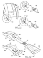
- a first rigid plate 76 can be incorporated within exterior pocket 52.
- a second rigid plate 78 can be provided within pocket 54. Plates 76 and 78 are preferably shaped such that they are slightly curved and/or form a relatively small angle at approximately their halfway points (See Figure 14). The curvature of rigid plate 76 helps to conform the associated dive equipment with the user's body, by making the equipment choose a position on the user's body. The curvature of second rigid plate 78 helps for inserting ballast member 56. In one embodiment, ballast member 56 can be constructed from lead. However, numerous other members, which provide ballast (i.e. other metals, sand, pieces of concrete, etc.) can also be used and all are considered within the scope of the invention.
- plates 76 and 78 can be constructed from a relatively rigid plastic such as ABS.
- a relatively rigid plastic such as ABS.
- numerous other rigid materials can be used for constructing plates 76 and 78 and all are considered within the scope of the invention.
- Plates 76 and 78, preferably hip contoured, provided in outer pocket 52 and weight pouch 54 create a crisp contact area with the diver's body, along with a correct and comfortable fit. Given the ease of removal or insertion of weight 56, especially when plates 76 and 78 are provided, the present invention diminishes the user's inhibition to practice don and doff of ballast, which can be a valuable safety feature.
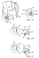
- side release buckle 61 As seen in Figure 23, the position of side release buckle 61 on the dive equipment (i.e. BC 51, Figure 15) allows it to act as a single point active fastening device and handle, with either its male or female section 62 or 64 attached to removable pocket/pouch 54 with twin mating plates 78 and 76 associated with removable pocket 54 and fixed pocket 52, respectively.
- This embodiment can also be provided with adjustability mechanism 63 for the webbing (strap 60) on at least lock side 62 or 64 of side release buckle 61 for total tensioning of variable ballast content 56 (See Figure 16).
- the position of side release buckle 61 on the dive equipment allows it to act as a single point active fastening device and handle, with either its male or female section 62 or 64 attached to removable pocket/pouch 54 with a single plate 76 provided in fixed pocket 52.
- This embodiment can also be provided with adjustability mechanism 63 for the webbing (strap 60) on at least lock side 62 or 64 of side release buckle 61 for total tensioning of variable ballast content 56 (See Figure 17).
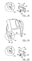
- the position of side release buckle 61 on the dive equipment allows it to act as a single point active fastening device and handle, with either its male or female section 62 or 64 attached to removable pocket/pouch 54 with single plate 78 provided in removable pocket 54.
- This embodiment can also be provided with adjustability mechanism 63 for the webbing (strap 60) on at least lock side 62 or 64 of side release buckle 61 for total tensioning of variable ballast content 56 (See Figure 18).
- adjustability mechanism 63 for the webbing (strap 60) on at least lock side 62 or 64 of side release buckle 61 for total tensioning of variable ballast content 56 See Figure 18.
- the position of side release buckle 61 on the dive equipment allows it to act as a single point active fastening device and handle, with either its male or female section 62 or 64 attached to removable pocket/pouch 54. In this embodiment no plates are provided.
- This embodiment can also be provided with adjustability mechanism 63 for the webbing (strap 60) on at least lock side 62 or 64 of side release buckle 61 for total tensioning of variable ballast content 56 (See Figure 20).
- Strap 58 or 60 can be an adjustable tensioning strap, and can be provided with hook and loop fastening members at its termination point, which preferably passes through the lock portion of side release buckle 61, to eliminate the movement of stored weight 56 (ballast). Once strap 58 or 60 has been properly adjusted, the hook and loop fasteners mate with other hook and loop fasteners to retain strap 58 or 60 against pocket 52, the dive equipment or some other area.
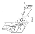
- a first alternative embodiment for system 50 is shown in Figures 2, 4 and 13.
- This alternative embodiment eliminates separate handle 66, by attaching strap 60 and either male insertion member 62 or female insertion member to removable pocket/pouch 54. All other structure is similar to the embodiment shown in Figures 1, 3, 8 and 9.
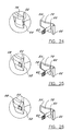
- strap 60 associated with side release buckle 61 can be attached directly to removable ballast pocket 54 and acts as singular attachment mechanism and single point active fastening device and handle for control of ballast component 56 pre-insertion, during use and post release.
- strap 60 can also be attached directly to ballast member 56 ( Figures 21 and 27).
- ballast member 56 can be provided without any curvature.
- This embodiment can also be provided with adjustability mechanism 63 for the webbing (strap 60) on at least lock side 62 or 64 of side release buckle 61 for total tensioning of variable ballast content 56 (See Figure 21).
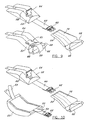
- side release buckle 61 As seen in Figure 28, the position of side release buckle 61 on the dive equipment allows it to act as a single point active fastening device and handle, with either its male or female section 62 or 64 attached to a removable machine formed box 67. Box 67 acts as a variable capacity ballast containing structure allowing easier insertion or removal of ballast member 56.
- This embodiment can also be provided with adjustability mechanism 63 for the webbing (strap 60) on at least lock side 62 or 64 of side release buckle 61 for total tensioning of variable ballast content 56 (See Figure 22).
- FIGS 29-33 illustrate various versions of a further embodiment of the active control releasable ballast system of the present invention.
- Side release buckle 61 with or without strap provided over removable pocket/pouch 54 perpendicular to the length of pocket 52 and forming a closure of the outer material over a mouth of pocket 52 sufficiently tight so as to reliably secure any enclosed ballast member 56.
- Activation (separation-release) of side release buckle 61 sufficiently removes the tension holding the face/mouth of fixed pocket 52 closed over removable pocket 54 so that any internally disposed ballast member 56 can be actively removed by means of grabbing removable pocket 54 ( Figure 30), handle 66 attached to removable pocket 54 ( Figure 31), or even a raw ballast component 56 itself (Figure 33).
- side release buckle 61 acts as a single point active fastening device by simply securing removable ballast pocket 54 inside fixed pocket 52 by closing a pleated expandable "mouth” section of the outer fabric of a fixed buoyancy compensator ballast system pocket 52.
- side release buckle 61 acts as a single point active fastening device by securing removable ballast pocket 54, with handle 66, inside fixed pocket 52 by closing the pleated expandable "mouth” section of the outer fabric of fixed buoyancy compensator ballast system pocket 52 over strap 68 of handle 66, such that handle 66 of removable pocket 54 is predisposed to being easily located immediately adjacent to side release buckle 61 for single action release and subsequent control via handle 66.
- an elastic bridge 71 can be added to the embodiment of Figure 29 to further secure ballast 56 when side release buckle 61 is in an open position to a degree in which reasonable effort of pull releases ballast member 56 in a controlled fashion.
- Side release buckle 61 acts as single point active fastening device by securing removable ballast member 56 itself inside fixed pocket 52 by sufficiently closing the pleated expandable "mouth" section of the outer fabric of fixed buoyancy compensator ballast pocket 52 closed ( Figure 33).
- the half of side release buckle 61 which is attached to weight member 56 or weight member pocket 54, be pre-disposed in a ergonomically disposed position that allows a natural and intuitive acquisition by the wearer (diver) and/or his or her dive buddy after disengagement from the other half of side release buckle 61.
- This same concept applies to the cold-water/technical version embodiments of the present that are provided with a separate handle 66 attached to weight member 56 or pocket 54 with both pieces of side release buckle 61 remaining attached to the dive equipment such as, but not limited to, dive belt 53 or buoyancy compensator 51.
- the present invention is also unique in that it provides for active control of releasable ballast 56 in sequential fashion with time/use irrelevance.
- side release buckle 61 such as, but not limited to a fastex buckle, as the release mechanism is also unique and teaches away from current industry thinking and focus of hook and loop release mechanisms.
- the use of side release buckle 61 is completely reliable, predictable, and typically cost less than hook and loop release mechanisms.
- Side release buckle 61 is a positive acting device and provides audible and tactile indication of engagement, which is not provided with current hook and loop mechanisms.
- Side release buckle 61 is not limited to any one color.
- Side release buckle 61 preferably requires two distinct ergonomically opposed fingers to cause the action of disengagement of male and female sections 62 and 64 of buckle 61 to occur, negating the concern of accidental release to as close to zero as mechanically feasible yet retaining superior ease of release.
- the structure of buckle 61 also allows for the release of weight 56 to be a deliberate and conscious act by the releaser (i.e. diver, dive buddy, etc.).
- the positioning of the active control ballast systems 50 on the dive equipment allows opposing fingers of either hand of the diver or dive buddy to either active control ballast system 50 attached to the dive equipment, which is typically two systems. However, one or more systems 50 can be attached to the dive equipment and all are considered within the scope of the invention.
- all of the embodiments and versions of active control ballast system 50 can be provided as a removably attachable fixed pocket 52 system.
- This removable embodiment can be used or set for Technical Back Plate Harness type BC systems and as an add on to other dive equipment, such as, but not limited to, dive belts.
- the removable design can be constructed to universally fit most of the popular Technical diving back plate harness systems in service today.
- the various embodiments and versions of the present invention can be permanently fabricated into the dive equipment, such as a conventional BC system 51 pocket area (preferably behind/below/inside of, and without interfering with convention BC exterior pocket 55) or on a dive belt 53, when originally manufactured (See Figures 11,15 and 19).
- all of the versions of system 50 can be provided as a retrofit/upgrade with the use of field usable fastening devices such as snap rivets, grommets, common sewing, loops, etc.
- side release buckle 61 and straps 58 and 60 can be provided over pocket 52 parallel to the length of pocket 52 and perpendicular over a mouth portion of pocket 52. This position of system 50 allows the invention to act as a singular attachment mechanism and single point active fastening device and handle for the control of ballast component 56 pre-insertion, during use and post release.
- removable pouch 54 At least a portion, and preferably a large percentage of the interior surfaces of removable pouch 54 can be covered with hook and loop fastening members 75.
- ballast member 56 is not limited to any one particular size, shape or poundage of weight, and all various sizes, shape or weight for ballast member 56 can be used and are considered within the scope of the invention. Furthermore, the type of material used for weight 56 is also not considered limited to any one type of material.
- active control ballast system 50 preferably the installer removes conventional equipment attached to the waist belt of the harness or a dive belt.
- the belt harness is then threaded through a sleeve 79 in the back of fixed pouch 52.
- a grommet nearest the pouch 52 can preferably line up with the holes in a bottom corner of a conventional backplate (not shown), and can be secured with a nut and bolt.
- the grommets on the end of the webbing preferably line up with bottom tank mounting holes of the backplate. These grommets can be preferably secured with the bottom tank mounting bolts.
- System 50 can also be provided with a D-ring on one side and can be provided with a relatively small of webbing, preferably two (2") inches, and a buckle. The webbing and buckle secures a light canister in the DIR position.
- All embodiments and versions of active control ballast system 50 provide all of the benefits associated with an integrated weight system, while leaving only one unavoidable hassle-weight.
- Active control ballast system 50 preferably suspends its weight 56 within the perfect position of the dive belt, BC/Harness system or other dive equipment. As the weight bearing area is preferably distributed closer to the diver's buoyant torso area, the active control ballast system substantially improves the diver trim and control.
- the active control ballast embodiments and versions of the present invention allow intelligent management of diver's ballast 56, as the diver is in control of buoyancy and trim both in and out of the water.
- side release buckle 61 is specifically chosen to resolve the issue of accidental release by a variety of undetectable situations that often occur when diving. Divers frequent closed in areas in reefs, shipwrecks, and cave systems to name a few. While in close confines a single point release mechanism could potentially come loose without warning by simply making contact with another object. Side release buckle 61 solves this problem by requiring simultaneous activation of two bilaterally opposed, but perfectly ambidextrously disposed "locks". Activation of one of two will not release the weight-retaining member, thus the term Active Control Ballast.
- the entire active control ballast design is based around active securement/release and optimum use insertion/release on either side by either hand by either the diver or buddy.
- side release buckle 61 is preferred, it is also within the scope of the invention, and considered a substantial improvement over previous designs, to provide a single point, but positive locking device such as a mono-lock side release or push button style mechanical fastener. All the same benefits as above apply except the added safety of the dual simultaneous activation.
- These alternative positive locking designs are also sufficient technology to those divers that carry an absolute minimum amount of releasable ballast. These designs are preferably used, though not limiting, when an amount of releasable ballast is contained in the active control ballast unit that would not cause a catastrophic rate of ascent in the event of an accidental release of ballast.
- the present invention prevents accidental weight release. Rapid and intentional insertion or removal of weight 56 is possible with either hand by the diver and/or the diver's dive buddy.
- active control ballast can be used with a dive belt, weight belt, diver harness, life vest, life jacket, buoyancy compensator, etc., and all are considered within the scope of the invention.
- each of the various embodiments can be incorporated on the other original piece of dive equipment (i.e. belt, buoyancy compensator, etc.) or can be provided as a stand alone accessory or upgrade for later attachment to preexisting dive equipment, all of these uses are also considered within the scope of the invention.
Landscapes
- Engineering & Computer Science (AREA)
- Mechanical Engineering (AREA)
- Ocean & Marine Engineering (AREA)
- Emergency Lowering Means (AREA)
- Agricultural Chemicals And Associated Chemicals (AREA)
- Circuit Arrangements For Discharge Lamps (AREA)
- Arrangement Of Elements, Cooling, Sealing, Or The Like Of Lighting Devices (AREA)
Claims (14)
- Durch aktive Kontrolle freisetzbares Ballastsystem für einen Tauchausrüstungsgegenstand, miteiner Ballast aufnehmenden Tasche (52),einem Ballastteil (56), das innerhalb der Aufnahmetasche vor der Freisetzung des Ballasts gelagert ist,einem ersten Gurt (58), der an oder nahe bei der Aufnahmetasche befestigt ist, undeinem zweiten Gurt (60), der an oder nahe bei der Aufnahmetasche befestigt ist,dadurch gekennzeichnet, dass das System weiter ein von der Seite zu öffnendes Gurtschloss (61) mit einem ersten Abschnitt und einem zweiten Abschnitt (62, 64) aufweist, wobei der erste Abschnitt des von der Seite zu öffnenden Gurtschlosses an dem ersten Gurt befestigt ist, der zweite Abschnitt des von der Seite zu öffnenden Gurtschlosses an dem zweiten Gurt befestigt ist, wobei vor dem Freisetzen des Ballastteils der erste Abschnitt und der zweite Abschnitt miteinander verbunden sind, um so das Ballastteil (56) innerhalb der Ballastaufnahmetasche (52) zu sichern.
- Durch aktive Kontrolle freisetzbares Ballastsystem (50) nach Anspruch 1, das weiter einen Beutel (54) zum Halten des Ballastteils (56) aufweist, wobei der Beutel vor der Freisetzung des Ballastteils und des Beutels innerhalb der Aufnahmetasche (52) gelagert ist.
- Durch aktive Kontrolle freisetzbares Ballastsystem (50) nach Anspruch 2, wobei der zweite Gurt (60) an dem Beutel (54) befestigt ist.
- Durch aktive Kontrolle freisetzbares Ballastsystem (50) nach Anspruch 1, wobei der zweite Gurt (60) an der Aufnahmetasche (52) befestigt ist.
- Durch aktive Kontrolle freisetzbares Ballastsystem (50) nach Anspruch 1, wobei der zweite Gurt (60) zur Befestigung an dem Tauchausrüstungsgegenstand ausgestaltet ist.
- Durch aktive Kontrolle freisetzbares Ballastsystem (50) nach Anspruch 1, wobei der zweite Gurt (60) an dem Ballastteil (56) befestigt ist.
- Durch aktive Kontrolle freisetzbares Ballastsystem (50) nach Anspruch 2, das weiter einen an dem Beutel (54) befestigten Griff (66) aufweist.
- Durch aktive Kontrolle freisetzbares Ballastsystem (50) nach Anspruch 1, das weiter einen an dem Ballastteil (56) befestigten Griff (66) aufweist.
- Durch aktive Kontrolle freisetzbares Ballastsystem (50) nach Anspruch 1, das weiter eine leicht gekrümmte Platte (76) aufweist, die innerhalb der Aufnahmetasche (52) angeordnet und befestigt ist.
- Durch aktive Kontrolle freisetzbares Ballastsystem (50) nach Anspruch 2, das weiter eine leicht gekrümmte Platte (78) aufweist, die innerhalb des Beutels (54) angeordnet und befestigt ist.
- Durch aktive Kontrolle freisetzbares Ballastsystem (50) nach Anspruch 2, das weiter eine erste leicht gekrümmte Platte (76), die innerhalb der Aufnahmetasche (52) angeordnet und daran befestigt ist, und eine zweite leicht gekrümmte Platte (78) aufweist, die innerhalb des Beutels (54) angeordnet und daran befestigt ist.
- Durch aktive Kontrolle freisetzbares Ballastsystem (50) nach Anspruch 2, wobei der Beutel (54) eine Klappe hat.
- Durch aktive Kontrolle freisetzbares Ballastsystem (50) nach Anspruch 1, wobei eine Stelle des von der Seite zu öffnenden Gurtschlosses (61) mit Bezug auf die Aufnahmetasche (52) eine aktive Ein-Punkt-Verschlusseinrichtung und einen Griff für aktive Kontrolle des Ballasts vor Einsetzen, während der Benutzung und nach dem Freisetzen des Ballasts bietet.
- Tarierweste (51) mit:einem Körperteil, undeinem durch aktive Kontrolle freisetzbaren Ballastsystem (50) nach einem der vorhergehenden Ansprüche, das an dem Körperteil befestigt ist.
Applications Claiming Priority (7)
| Application Number | Priority Date | Filing Date | Title |
|---|---|---|---|
| US730116 | 1996-08-08 | ||
| US62883600A | 2000-07-31 | 2000-07-31 | |
| US628836 | 2000-07-31 | ||
| US09/730,116 US7458751B2 (en) | 2000-12-05 | 2000-12-05 | Active control releasable ballast system for use with dive equipment |
| US916414 | 2001-07-26 | ||
| US09/916,414 US6527480B2 (en) | 2000-07-31 | 2001-07-26 | Buoyancy compensator weight system |
| PCT/US2001/023638 WO2002010012A1 (en) | 2000-07-31 | 2001-07-27 | Active control releasable ballast system for use with dive equipment |
Publications (3)
| Publication Number | Publication Date |
|---|---|
| EP1404571A1 EP1404571A1 (de) | 2004-04-07 |
| EP1404571A4 EP1404571A4 (de) | 2005-08-17 |
| EP1404571B1 true EP1404571B1 (de) | 2006-11-02 |
Family
ID=27417460
Family Applications (1)
| Application Number | Title | Priority Date | Filing Date |
|---|---|---|---|
| EP01955992A Expired - Lifetime EP1404571B1 (de) | 2000-07-31 | 2001-07-27 | Durch aktive kontrolle auslösbares ballastsystem für taucher |
Country Status (5)
| Country | Link |
|---|---|
| EP (1) | EP1404571B1 (de) |
| AT (1) | ATE344176T1 (de) |
| AU (1) | AU2001278037A1 (de) |
| DE (1) | DE60124323T2 (de) |
| WO (1) | WO2002010012A1 (de) |
Families Citing this family (4)
| Publication number | Priority date | Publication date | Assignee | Title |
|---|---|---|---|---|
| ITFI20020049U1 (it) * | 2002-05-07 | 2003-11-07 | Cressi Sub Spa | Giubbetto equilibratore da sub con tasche portapesi modificate |
| ITFI20060143A1 (it) | 2006-06-09 | 2007-12-10 | Cressi Sub Spa | Dispositivo di connessione reversibile di un astuccio portapesi a una tasca di un giubotto da subacqueo |
| RU174713U1 (ru) * | 2016-12-16 | 2017-10-30 | Общество с ограниченной ответственностью "Научно-производственное предприятие "Морские Спасательные Средства" | Жилет спасательный надувной |
| CN115339596A (zh) * | 2022-09-16 | 2022-11-15 | 中国科学院深海科学与工程研究所 | 一种深海自主无人车抛载装置 |
Family Cites Families (8)
| Publication number | Priority date | Publication date | Assignee | Title |
|---|---|---|---|---|
| US4694772A (en) * | 1985-06-17 | 1987-09-22 | U.S.D. Corp | Diver's buoyancy compensator belt |
| US5074714A (en) * | 1990-08-13 | 1991-12-24 | George Franco | Independent scuba tank stabilizing/weight ballast frame |
| US5205672A (en) * | 1992-01-14 | 1993-04-27 | Diving Unlimited International, Inc. | Diver's weight assembly |
| US5746542A (en) * | 1995-11-17 | 1998-05-05 | Carmichael; Robert M. | Drop weight dive belt |
| US5944450A (en) * | 1996-08-30 | 1999-08-31 | Johnson Worldwide Associates | Integral buoyancy and ballast system for scuba divers |
| US5860769A (en) * | 1996-09-04 | 1999-01-19 | Seaquest, Inc. | Combination buoyancy compensator and support for a diver's backpack with a swivel buckle and triangular holder |
| US5913640A (en) * | 1997-10-22 | 1999-06-22 | Bortner; R. Blake | Weight drop pocket for SCUBA divers |
| US6030147A (en) * | 1998-03-13 | 2000-02-29 | Dacor Corporation | Torso-conforming releasable diver's weight pouch |
-
2001
- 2001-07-27 DE DE60124323T patent/DE60124323T2/de not_active Expired - Lifetime
- 2001-07-27 WO PCT/US2001/023638 patent/WO2002010012A1/en not_active Ceased
- 2001-07-27 EP EP01955992A patent/EP1404571B1/de not_active Expired - Lifetime
- 2001-07-27 AT AT01955992T patent/ATE344176T1/de not_active IP Right Cessation
- 2001-07-27 AU AU2001278037A patent/AU2001278037A1/en not_active Abandoned
Also Published As
| Publication number | Publication date |
|---|---|
| EP1404571A1 (de) | 2004-04-07 |
| AU2001278037A1 (en) | 2002-02-13 |
| DE60124323D1 (de) | 2006-12-14 |
| ATE344176T1 (de) | 2006-11-15 |
| WO2002010012A1 (en) | 2002-02-07 |
| EP1404571A4 (de) | 2005-08-17 |
| DE60124323T2 (de) | 2007-07-05 |
Similar Documents
| Publication | Publication Date | Title |
|---|---|---|
| US8272809B2 (en) | Active control releasable ballast system for use with dive equipment | |
| US6487761B2 (en) | Quick release buckle for divers | |
| US5205672A (en) | Diver's weight assembly | |
| US5562513A (en) | Buoyancy compensator device with backpack and adjustable harness | |
| US4455718A (en) | Scuba tank weight strap | |
| US20090148240A1 (en) | Dive belt | |
| CN102123632B (zh) | 具有紧固件的容器保持装置 | |
| US6030147A (en) | Torso-conforming releasable diver's weight pouch | |
| US6527480B2 (en) | Buoyancy compensator weight system | |
| EP2437975B1 (de) | System mit schnell einzustellenden durchgehenden webstoffschutzplatten | |
| US5085163A (en) | Weight release system | |
| US5944450A (en) | Integral buoyancy and ballast system for scuba divers | |
| EP1565077B1 (de) | Persönliche schwimmvorrichtung | |
| US20190104809A1 (en) | Modular locking connectors for portable harness systems, methods and devices | |
| US4846744A (en) | Adjustable footstrap for sailboard | |
| EP1404571B1 (de) | Durch aktive kontrolle auslösbares ballastsystem für taucher | |
| US9809287B2 (en) | Container holder with fasteners | |
| US6881011B1 (en) | Buoyancy compensator, utility backpack, transport harness or like garment with adjustable one size component for use by a wide range of individuals | |
| US6478509B2 (en) | Harness weight transfer system for scuba diving | |
| CN221082927U (zh) | 一种用于救生设备的快速系附结构及救生衣 | |
| US20250242898A1 (en) | Buoyancy Compensator Integrated Weight System | |
| US20060018718A1 (en) | Connector having a mechanical lock and a one-step release | |
| CA1140092A (en) | Safety harness | |
| WO2025165842A1 (en) | Buoyancy compensator integrated weight system | |
| WO2025106359A1 (en) | Free diving weight belts with accessory attachments |
Legal Events
| Date | Code | Title | Description |
|---|---|---|---|
| PUAI | Public reference made under article 153(3) epc to a published international application that has entered the european phase |
Free format text: ORIGINAL CODE: 0009012 |
|
| 17P | Request for examination filed |
Effective date: 20030603 |
|
| AK | Designated contracting states |
Kind code of ref document: A1 Designated state(s): AT BE CH CY DE DK ES FI FR GB GR IE IT LI LU MC NL PT SE TR |
|
| A4 | Supplementary search report drawn up and despatched |
Effective date: 20050705 |
|
| RIC1 | Information provided on ipc code assigned before grant |
Ipc: 7B 63C 11/02 A Ipc: 7B 63C 9/08 B Ipc: 7B 63C 11/00 B Ipc: 7B 63C 11/30 B |
|
| GRAP | Despatch of communication of intention to grant a patent |
Free format text: ORIGINAL CODE: EPIDOSNIGR1 |
|
| GRAS | Grant fee paid |
Free format text: ORIGINAL CODE: EPIDOSNIGR3 |
|
| GRAA | (expected) grant |
Free format text: ORIGINAL CODE: 0009210 |
|
| AK | Designated contracting states |
Kind code of ref document: B1 Designated state(s): AT BE CH CY DE DK ES FI FR GB GR IE IT LI LU MC NL PT SE TR |
|
| PG25 | Lapsed in a contracting state [announced via postgrant information from national office to epo] |
Ref country code: LI Free format text: LAPSE BECAUSE OF FAILURE TO SUBMIT A TRANSLATION OF THE DESCRIPTION OR TO PAY THE FEE WITHIN THE PRESCRIBED TIME-LIMIT Effective date: 20061102 Ref country code: AT Free format text: LAPSE BECAUSE OF FAILURE TO SUBMIT A TRANSLATION OF THE DESCRIPTION OR TO PAY THE FEE WITHIN THE PRESCRIBED TIME-LIMIT Effective date: 20061102 Ref country code: FI Free format text: LAPSE BECAUSE OF FAILURE TO SUBMIT A TRANSLATION OF THE DESCRIPTION OR TO PAY THE FEE WITHIN THE PRESCRIBED TIME-LIMIT Effective date: 20061102 Ref country code: CH Free format text: LAPSE BECAUSE OF FAILURE TO SUBMIT A TRANSLATION OF THE DESCRIPTION OR TO PAY THE FEE WITHIN THE PRESCRIBED TIME-LIMIT Effective date: 20061102 |
|
| REG | Reference to a national code |
Ref country code: GB Ref legal event code: FG4D |
|
| REG | Reference to a national code |
Ref country code: IE Ref legal event code: FG4D |
|
| REG | Reference to a national code |
Ref country code: CH Ref legal event code: EP |
|
| REF | Corresponds to: |
Ref document number: 60124323 Country of ref document: DE Date of ref document: 20061214 Kind code of ref document: P |
|
| PG25 | Lapsed in a contracting state [announced via postgrant information from national office to epo] |
Ref country code: SE Free format text: LAPSE BECAUSE OF FAILURE TO SUBMIT A TRANSLATION OF THE DESCRIPTION OR TO PAY THE FEE WITHIN THE PRESCRIBED TIME-LIMIT Effective date: 20070202 Ref country code: DK Free format text: LAPSE BECAUSE OF FAILURE TO SUBMIT A TRANSLATION OF THE DESCRIPTION OR TO PAY THE FEE WITHIN THE PRESCRIBED TIME-LIMIT Effective date: 20070202 |
|
| PG25 | Lapsed in a contracting state [announced via postgrant information from national office to epo] |
Ref country code: ES Free format text: LAPSE BECAUSE OF FAILURE TO SUBMIT A TRANSLATION OF THE DESCRIPTION OR TO PAY THE FEE WITHIN THE PRESCRIBED TIME-LIMIT Effective date: 20070213 |
|
| PG25 | Lapsed in a contracting state [announced via postgrant information from national office to epo] |
Ref country code: PT Free format text: LAPSE BECAUSE OF FAILURE TO SUBMIT A TRANSLATION OF THE DESCRIPTION OR TO PAY THE FEE WITHIN THE PRESCRIBED TIME-LIMIT Effective date: 20070402 |
|
| REG | Reference to a national code |
Ref country code: CH Ref legal event code: PL |
|
| EN | Fr: translation not filed | ||
| PLBE | No opposition filed within time limit |
Free format text: ORIGINAL CODE: 0009261 |
|
| STAA | Information on the status of an ep patent application or granted ep patent |
Free format text: STATUS: NO OPPOSITION FILED WITHIN TIME LIMIT |
|
| 26N | No opposition filed |
Effective date: 20070803 |
|
| PG25 | Lapsed in a contracting state [announced via postgrant information from national office to epo] |
Ref country code: GR Free format text: LAPSE BECAUSE OF FAILURE TO SUBMIT A TRANSLATION OF THE DESCRIPTION OR TO PAY THE FEE WITHIN THE PRESCRIBED TIME-LIMIT Effective date: 20070203 Ref country code: FR Free format text: LAPSE BECAUSE OF FAILURE TO SUBMIT A TRANSLATION OF THE DESCRIPTION OR TO PAY THE FEE WITHIN THE PRESCRIBED TIME-LIMIT Effective date: 20070615 |
|
| ET | Fr: translation filed | ||
| REG | Reference to a national code |
Ref country code: FR Ref legal event code: EERR Free format text: CORRECTION DE BOPI 07/24 - BREVETS EUROPEENS DONT LA TRADUCTION N A PAS ETE REMISE A L INPI. IL Y A LIEU DE SUPPRIMER : LA MENTION DE LA NON-REMISE. LA REMISE DE LA TRADUCTION EST PUBLIEE DANS LE PRESENT BOPI. |
|
| REG | Reference to a national code |
Ref country code: GB Ref legal event code: 732E |
|
| PG25 | Lapsed in a contracting state [announced via postgrant information from national office to epo] |
Ref country code: IE Free format text: LAPSE BECAUSE OF NON-PAYMENT OF DUE FEES Effective date: 20070727 |
|
| PG25 | Lapsed in a contracting state [announced via postgrant information from national office to epo] |
Ref country code: LU Free format text: LAPSE BECAUSE OF NON-PAYMENT OF DUE FEES Effective date: 20070727 Ref country code: CY Free format text: LAPSE BECAUSE OF FAILURE TO SUBMIT A TRANSLATION OF THE DESCRIPTION OR TO PAY THE FEE WITHIN THE PRESCRIBED TIME-LIMIT Effective date: 20061102 |
|
| PG25 | Lapsed in a contracting state [announced via postgrant information from national office to epo] |
Ref country code: TR Free format text: LAPSE BECAUSE OF FAILURE TO SUBMIT A TRANSLATION OF THE DESCRIPTION OR TO PAY THE FEE WITHIN THE PRESCRIBED TIME-LIMIT Effective date: 20061102 |
|
| PGFP | Annual fee paid to national office [announced via postgrant information from national office to epo] |
Ref country code: NL Payment date: 20100731 Year of fee payment: 10 |
|
| PGFP | Annual fee paid to national office [announced via postgrant information from national office to epo] |
Ref country code: IT Payment date: 20100726 Year of fee payment: 10 Ref country code: DE Payment date: 20100722 Year of fee payment: 10 |
|
| PGFP | Annual fee paid to national office [announced via postgrant information from national office to epo] |
Ref country code: GB Payment date: 20100728 Year of fee payment: 10 |
|
| PGFP | Annual fee paid to national office [announced via postgrant information from national office to epo] |
Ref country code: BE Payment date: 20100729 Year of fee payment: 10 |
|
| PGFP | Annual fee paid to national office [announced via postgrant information from national office to epo] |
Ref country code: MC Payment date: 20110128 Year of fee payment: 10 |
|
| PGFP | Annual fee paid to national office [announced via postgrant information from national office to epo] |
Ref country code: FR Payment date: 20110211 Year of fee payment: 10 |
|
| BERE | Be: lapsed |
Owner name: CARMICHAEL, ROBERT M. Effective date: 20110731 |
|
| REG | Reference to a national code |
Ref country code: NL Ref legal event code: V1 Effective date: 20120201 |
|
| PG25 | Lapsed in a contracting state [announced via postgrant information from national office to epo] |
Ref country code: MC Free format text: LAPSE BECAUSE OF NON-PAYMENT OF DUE FEES Effective date: 20110731 |
|
| GBPC | Gb: european patent ceased through non-payment of renewal fee |
Effective date: 20110727 |
|
| REG | Reference to a national code |
Ref country code: FR Ref legal event code: ST Effective date: 20120330 |
|
| PG25 | Lapsed in a contracting state [announced via postgrant information from national office to epo] |
Ref country code: FR Free format text: LAPSE BECAUSE OF FAILURE TO SUBMIT A TRANSLATION OF THE DESCRIPTION OR TO PAY THE FEE WITHIN THE PRESCRIBED TIME-LIMIT Effective date: 20110801 Ref country code: DE Free format text: LAPSE BECAUSE OF NON-PAYMENT OF DUE FEES Effective date: 20120201 Ref country code: BE Free format text: LAPSE BECAUSE OF NON-PAYMENT OF DUE FEES Effective date: 20110731 |
|
| REG | Reference to a national code |
Ref country code: DE Ref legal event code: R119 Ref document number: 60124323 Country of ref document: DE Effective date: 20120201 |
|
| PG25 | Lapsed in a contracting state [announced via postgrant information from national office to epo] |
Ref country code: IT Free format text: LAPSE BECAUSE OF NON-PAYMENT OF DUE FEES Effective date: 20110727 Ref country code: NL Free format text: LAPSE BECAUSE OF NON-PAYMENT OF DUE FEES Effective date: 20120201 |
|
| PG25 | Lapsed in a contracting state [announced via postgrant information from national office to epo] |
Ref country code: GB Free format text: LAPSE BECAUSE OF NON-PAYMENT OF DUE FEES Effective date: 20110727 |