EP1403951A2 - Fuel cell seals - Google Patents
Fuel cell seals Download PDFInfo
- Publication number
- EP1403951A2 EP1403951A2 EP20030256048 EP03256048A EP1403951A2 EP 1403951 A2 EP1403951 A2 EP 1403951A2 EP 20030256048 EP20030256048 EP 20030256048 EP 03256048 A EP03256048 A EP 03256048A EP 1403951 A2 EP1403951 A2 EP 1403951A2
- Authority
- EP
- European Patent Office
- Prior art keywords
- reactant gas
- coolant
- flow field
- fuel cell
- oxygen
- Prior art date
- Legal status (The legal status is an assumption and is not a legal conclusion. Google has not performed a legal analysis and makes no representation as to the accuracy of the status listed.)
- Granted
Links
Images


Classifications
-
- H—ELECTRICITY
- H01—ELECTRIC ELEMENTS
- H01M—PROCESSES OR MEANS, e.g. BATTERIES, FOR THE DIRECT CONVERSION OF CHEMICAL ENERGY INTO ELECTRICAL ENERGY
- H01M8/00—Fuel cells; Manufacture thereof
- H01M8/02—Details
- H01M8/0202—Collectors; Separators, e.g. bipolar separators; Interconnectors
- H01M8/0258—Collectors; Separators, e.g. bipolar separators; Interconnectors characterised by the configuration of channels, e.g. by the flow field of the reactant or coolant
- H01M8/0263—Collectors; Separators, e.g. bipolar separators; Interconnectors characterised by the configuration of channels, e.g. by the flow field of the reactant or coolant having meandering or serpentine paths
-
- H—ELECTRICITY
- H01—ELECTRIC ELEMENTS
- H01M—PROCESSES OR MEANS, e.g. BATTERIES, FOR THE DIRECT CONVERSION OF CHEMICAL ENERGY INTO ELECTRICAL ENERGY
- H01M8/00—Fuel cells; Manufacture thereof
- H01M8/02—Details
- H01M8/0202—Collectors; Separators, e.g. bipolar separators; Interconnectors
- H01M8/0267—Collectors; Separators, e.g. bipolar separators; Interconnectors having heating or cooling means, e.g. heaters or coolant flow channels
-
- H—ELECTRICITY
- H01—ELECTRIC ELEMENTS
- H01M—PROCESSES OR MEANS, e.g. BATTERIES, FOR THE DIRECT CONVERSION OF CHEMICAL ENERGY INTO ELECTRICAL ENERGY
- H01M8/00—Fuel cells; Manufacture thereof
- H01M8/02—Details
- H01M8/0271—Sealing or supporting means around electrodes, matrices or membranes
-
- H—ELECTRICITY
- H01—ELECTRIC ELEMENTS
- H01M—PROCESSES OR MEANS, e.g. BATTERIES, FOR THE DIRECT CONVERSION OF CHEMICAL ENERGY INTO ELECTRICAL ENERGY
- H01M8/00—Fuel cells; Manufacture thereof
- H01M8/02—Details
- H01M8/0271—Sealing or supporting means around electrodes, matrices or membranes
- H01M8/0276—Sealing means characterised by their form
-
- H—ELECTRICITY
- H01—ELECTRIC ELEMENTS
- H01M—PROCESSES OR MEANS, e.g. BATTERIES, FOR THE DIRECT CONVERSION OF CHEMICAL ENERGY INTO ELECTRICAL ENERGY
- H01M8/00—Fuel cells; Manufacture thereof
- H01M8/24—Grouping of fuel cells, e.g. stacking of fuel cells
- H01M8/2465—Details of groupings of fuel cells
- H01M8/2483—Details of groupings of fuel cells characterised by internal manifolds
-
- H—ELECTRICITY
- H01—ELECTRIC ELEMENTS
- H01M—PROCESSES OR MEANS, e.g. BATTERIES, FOR THE DIRECT CONVERSION OF CHEMICAL ENERGY INTO ELECTRICAL ENERGY
- H01M8/00—Fuel cells; Manufacture thereof
- H01M8/10—Fuel cells with solid electrolytes
- H01M2008/1095—Fuel cells with polymeric electrolytes
-
- Y—GENERAL TAGGING OF NEW TECHNOLOGICAL DEVELOPMENTS; GENERAL TAGGING OF CROSS-SECTIONAL TECHNOLOGIES SPANNING OVER SEVERAL SECTIONS OF THE IPC; TECHNICAL SUBJECTS COVERED BY FORMER USPC CROSS-REFERENCE ART COLLECTIONS [XRACs] AND DIGESTS
- Y02—TECHNOLOGIES OR APPLICATIONS FOR MITIGATION OR ADAPTATION AGAINST CLIMATE CHANGE
- Y02E—REDUCTION OF GREENHOUSE GAS [GHG] EMISSIONS, RELATED TO ENERGY GENERATION, TRANSMISSION OR DISTRIBUTION
- Y02E60/00—Enabling technologies; Technologies with a potential or indirect contribution to GHG emissions mitigation
- Y02E60/30—Hydrogen technology
- Y02E60/50—Fuel cells
Definitions
- the present invention relates to a fuel cell including an electrolyte electrode assembly interposed between a pair of separators.
- the electrolyte electrode assembly includes a pair of electrodes, and an electrolyte interposed between the electrodes.
- a reactant gas supply passage and a reactant gas discharge passage extend through the separators in a stacking direction.
- a reactant gas flow field is connected between the reactant gas supply passage and the reactant gas discharge passage, and supplies a reactant gas to the electrode.
- a solid polymer electrolyte fuel cell employs a membrane electrode assembly (MEA) which comprises two electrodes (anode and cathode) and an electrolyte membrane interposed between the electrodes.
- the electrolyte membrane is a polymer ion exchange membrane.
- the membrane electrode assembly is interposed between separators. The membrane electrode assembly and the separators make up a unit of the fuel cell for generating electricity. A predetermined number of fuel cells are stacked together to form a fuel cell stack.
- a fuel gas such as a hydrogen-containing gas is supplied to the anode.
- the catalyst of the anode induces a chemical reaction of the fuel gas to split the hydrogen molecule into hydrogen ions (protons) and electrons.
- the hydrogen ions move toward the cathode through the electrolyte, and the electrons flow through an external circuit to the cathode, creating a DC electric current.
- An oxygen-containing gas or air is supplied to the cathode.
- the hydrogen ions from the anode combine with the electrons and oxygen to produce water.
- Japanese laid-open patent publication No. 2001-319667 discloses a fuel cell directed to improve the sealing characteristics.
- the fuel cell includes a membrane electrode assembly 1, and first and second separators 2, 3.
- the membrane electrode assembly 1 includes an anode 5, and a cathode 6, and a solid polymer electrolyte membrane 4 interposed between the anode 5 and the cathode 6.
- the anode 5 includes a gas diffusion layer 5a and an electrode catalyst layer 5b.
- the cathode 6 includes a gas diffusion layer 6a and an electrode catalyst layer 6b.
- the solid polymer electrolyte membrane 4 has an extension extending outwardly from the cathode 5 and the anode 6.
- the first and second separators 2, 3 have grooves 2a, 3a, respectively, at a position corresponding to the extension of the solid polymer electrolyte membrane 4.
- Liquid seals 7 are provided in the grooves 2a, 3a, respectively.
- the liquid seals 7 are made of a heat curing fluoride or silicone.
- the liquid seals 7 are applied in the grooves 2a, 3a in a liquid state. In the liquid state, the liquid seals 7 have a certain viscosity. In use, the liquid seals 7 are hardened to have a certain elasticity in a solid state.
- the liquid seals 7 are tightly in contact with the extension of the solid polymer electrolyte membrane 4, and end surfaces of the gas diffusion layers 5a, 6a, and the electrode catalyst layers 5b, 6b.
- the liquid seals 7 provided around the cathode 5 and the anode 6 are tightly in contact with the end surfaces of the gas diffusion layers 5a, 6a, and the electrode catalyst layers 5b, 6b due to the factor such as the tolerance in producing, and assembling the components. If there is a clearance between the liquid seals 7 and the gas diffusion layers 5a, 6a, the reactant gas may leak into the clearance. Some of the reactant gas such as an oxygen-gas and a fuel gas leaks into the reactant gas discharge passage through the clearance, and is not supplied to electrode surfaces of the cathode 5 and the anode 6. Consequently, the power generation can not be performed efficiently.
- a coolant for cooling the electrode surface may also leak into a coolant flow field through the clearance around the electrode surface. Since the coolant does not flow along the electrode surface, the electrode surface is not cooled by the coolant efficiently.
- a general object of the present invention is to provide a fuel cell with a simple structure in which a fluid such as a reactant gas does not leak out of a predetermined flow passage, and the desired power generation performance is maintained.
- an electrolyte electrode assembly includes a pair of electrodes and an electrolyte interposed between the electrodes. Separators sandwich the electrolyte electrode assembly. A reactant gas supply passage and a reactant gas discharge passage extend through the separators in a stacking direction. At least one of the separators has a reactant gas flow field connected between the reactant gas supply passage and the reactant gas discharge passage for supplying a reactant gas to the electrode. A seal member is provided around the electrode for sealing the reactant gas flow field, the reactant gas supply passage, and the reactant gas discharge passage. A filling seal is provided tightly in contact with at least an outer end surface of the electrode for preventing leakage of the reactant gas at an outer region of the electrode.
- the reactant gas does not flow through the clearance between the electrode and the seal member. Therefore, the reactant gas is reliably supplied to the surface of the electrode. Thus, the reactant gas is utilized efficiently, and the power generation performance is improved effectively. Further, the present invention is carried out simply by providing the filling seal tightly in contact with at least the electrode. Thus, the fuel cell has a simple structure, and can be produced economically.
- the filling seal may be provided near the reactant gas supply passage and near the reactant gas discharge passage.
- sealing is reliably performed near the reactant gas supply passage and the reactant gas discharge passage, i.e., at the positions where leakage of the reactant gas is likely to occur. Leakage of the reactant gas is greatly reduced with the simple structure.
- the reactant gas flow field may include at least one U-Turn region, and the filling seal may be provided near the U-Turn region for preventing leakage of the reactant gas from the U-Turn region.
- the reactant gas flow field comprises a serpentine reactant gas flow passage, leakage of the reactant gas is reliably prevented with the simple structure.
- At least one of the separators may have a coolant flow field for supplying a coolant to cool the electrode.
- An additional filling seal may be provided in a part of a clearance between the coolant flow field and the seal member for preventing leakage of the coolant into the clearance.
- the coolant does not flow directly flow from the coolant supply passage to the coolant discharge passage.
- the coolant flows along the coolant flow field suitably.
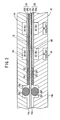
- FIG. 1 is an exploded perspective view showing main components of a fuel cell 10 according to a first embodiment of the present invention.
- FIG. 2 is a cross sectional view showing the main components of the fuel cell 10.
- the fuel cell 10 includes a membrane electrode assembly (electrolyte electrode assembly) 12, and first and second separators 14, 16 for sandwiching the membrane electrode assembly 12.
- a membrane electrode assembly electroactive electrode assembly
- first and second separators 14, 16 for sandwiching the membrane electrode assembly 12.
- a coolant discharge passage 22b for discharging a coolant and a fuel gas discharge passage (reactant gas discharge passage) 24b for discharging a fuel gas such as a hydrogen-containing gas
- the oxygen-containing gas supply passage 20a, the coolant discharge passage 22b, and the fuel gas discharge passage 24b extend through the fuel cell 10 in a stacking direction indicated by an arrow A.
- a fuel gas supply passage (reactant gas supply passage) 24a for supplying the fuel gas, a coolant supply passage 22a for supplying the coolant, and an oxygen-containing gas discharge passage (reactant gas discharge passage) 20b for discharging the oxygen-containing gas are arranged in the direction indicated by the arrow C.
- the fuel gas supply passage 24a, the coolant supply passage 22a, and the oxygen-containing gas discharge passage 20b extend through the fuel cell 10 in the direction indicated by the arrow A.
- the membrane electrode assembly 12 comprises an anode 28, a cathode 30, and a solid polymer electrolyte membrane 26 interposed between the anode 28 and the cathode 30.
- the solid polymer electrolyte membrane 26 is formed by impregnating a thin membrane of perfluorosulfonic acid with water, for example.
- each of the anode 28 and the cathode 30 has a gas diffusion layer (porous diffusion member) 32a, 32b, and an electrode catalyst layer 34a, 34b of platinum alloy supported on porous carbon particles.
- the carbon particles of the electrode catalyst layer 34a, 34b are deposited uniformly on the surface of the gas diffusion layer 32a, 32b.
- the electrode catalyst layer 34a of the anode 28 and the electrode catalyst layer 34b of the cathode 30 are fixed to both surfaces of the solid polymer electrolyte membrane 26, respectively.
- the first separator 14 has an oxygen-containing gas flow field (reactant gas flow field) 36 on its surface 14a facing the membrane electrode assembly 12.
- the oxygen-containing flow field 36 comprises a plurality of oxygen-containing gas grooves 38 extending in a serpentine pattern including two U-Turn regions 36a, 36b for allowing the oxygen-containing gas to flow horizontally back and forth in the direction indicated by the arrow B, and vertically in the direction indicated by the arrow C.
- the oxygen-containing gas grooves 38 of the oxygen-containing gas flow field 36 are connected to the oxygen-containing gas supply passage 20a at one end, and connected to the oxygen-containing gas discharge passage 20b at the other end.
- the second separator 16 has a fuel gas flow field (reactant gas flow field) 40 on it surface 16a facing the membrane electrode assembly 12.
- the fuel gas flow field 40 comprises a plurality of fuel gas grooves 42 extending in a serpentine pattern including two U-Turn regions 40a, 40b for allowing the fuel gas to flow horizontally back and forth, and vertically.
- the fuel gas grooves 42 of the fuel gas flow field 40 is connected to the fuel gas supply passage 24a at one end, and connected to the fuel gas discharge passage 24b at the other end.
- a coolant flow field 44 is formed between a surface 14b of the first separator 14 and a surface 16b of the second separator 16.
- the coolant flow field 44 comprises a plurality of coolant grooves 46 extending in a serpentine pattern including two U-Turn regions 44a, 44b for allowing the coolant to flow horizontally back and forth, and vertically.
- the coolant grooves 46 of the coolant flow field 44 is connected to the coolant supply passage 22a at one end, and connected to the coolant discharge passage 22b at the other end.
- a seal groove 48 is formed on the surface 14a of the first separator 14 around the cathode 30, i.e., around the oxygen-containing gas flow field 36, the oxygen-containing gas supply passage 20a, and the oxygen-containing gas discharge passage 20b.
- a seal member 50 is provided in the seal groove 48.
- filling seals 54 are provided at some positions in a clearance 52 between the cathode 30 and the seal member 50 for preventing leakage of the oxygen-containing gas into the clearance 52.
- the filling seals 54 are tightly in contact with at least the outer end surface of the cathode 30.
- the filling seals 54 are liquid seals or solid filling seals, for example.
- the filling seals 54 are provided at positions where leakage of the oxygen-containing gas is likely to occur.
- the filling seals 54 are provided in the clearance 52 near the oxygen-containing gas supply passage 20a, near the oxygen-containing gas discharge passage 20b, and near the U-Turn regions 36a, 36b.
- a seal groove 56 is formed on the surface 16a of the second separator 16 around the anode 28, i.e., around the fuel gas flow field 40, the fuel gas supply passage 24a, and the fuel gas discharge passage 24b.
- a seal member 58 is provided in the seal groove 56.
- Filling seals 62 are provided at some positions in a clearance 60 between the anode 28 and the seal member 58.
- the filling seals 62 are tightly in contact with at least the outer end surface of the anode 28.
- the filling seals 62 are provided at positions where leakage of the fuel gas is likely to occur.
- the filling seals 62 are provided in the clearance 60 near the fuel gas supply passage 24a, near the fuel gas discharge passage 24b, and near the U-Turn regions 40a, 40b.
- a seal groove 64 is formed on the surface 16b of the second separator 16 around the coolant flow field 44.
- a seal member 66 is provided in the seal groove 64.
- Filling seals 70 are provided at some positions in a clearance 68 between the coolant flow field 44 and the seal member 66. Specifically, the filling seals 70 are provided in the clearance 68 near the coolant supply passage 22a, near the coolant discharge passage 22b, and near the U-Turn regions 44a, 44b.
- an oxygen-containing gas is supplied to the oxygen-containing gas supply passage 20a, and a fuel gas such as a hydrogen-containing gas is supplied to the fuel gas supply passage 24a. Further, a coolant such as pure water, an ethylene glycol or an oil is supplied to the coolant supply passage 22a.
- the oxygen-containing gas flows from the oxygen-containing gas supply passage 20a into the oxygen-containing gas flow field 36 formed on the first separator 14, and flows through the oxygen-containing gas grooves 38 in the direction indicated by the arrow B in a serpentine pattern along the cathode 30 of the membrane electrode assembly 12 to induce an electrochemical reaction at the cathode 30.
- the fuel gas flows from the fuel gas supply passage 24a into the fuel gas flow field 40 formed on the second separator 16, and flows through the fuel gas grooves 42 in the direction indicated by the arrow B in a serpentine pattern along the anode 28 of the membrane electrode assembly 12 to induce an electrochemical reaction at the anode 28.
- the oxygen-containing gas supplied to the cathode 30, and the fuel gas supplied to the anode 28 are consumed in the electrochemical reactions at the electrode catalyst layers 34a, 34b of the cathode 30 and the anode 28 for generating electricity.
- the oxygen-containing gas is consumed at the cathode 30
- the oxygen-containing gas is discharged into the oxygen-containing gas discharge passage 20b, and flows in the direction indicated by the arrow A.
- the fuel gas is discharged into the fuel gas discharge passage 24b, and flows in the direction indicated by the arrow A.
- the coolant flows from the coolant supply passage 22a into the coolant flow field 44 between the first separator 14 and the second separator 16, and flows in the direction indicated by the arrow B in a serpentine pattern. After the coolant is used for cooling the membrane electrode assembly 12, the coolant is discharged into the coolant discharge passage 22b.
- the oxygen-containing gas flow field 36 comprises a passage of the oxygen-containing gas grooves 38 in the serpentine pattern formed on the surface 14a of the first separator 14, and the seal member 50 is provided in the seal groove 48 around the oxygen-containing gas flow field 36.
- the filling seals 54 are provided in the clearance 52 between the oxygen-containing gas flow field 36 and the seal member 50, at positions near the oxygen-containing gas supply passage 20a, near the oxygen-containing gas discharge passage 20b, and near the U-turn regions 36a, 36b.
- the filling seals 54 are provided at positions where leakage of the oxygen-containing gas into the clearance 52 is likely to occur. Therefore, the oxygen-containing gas does not flow along the clearance 52, and the oxygen-containing gas is reliably supplied to the electrode surface of the cathode 30. Since the oxygen-containing gas does not flow into the oxygen-containing gas discharge passage 20b through the clearance 52 around the cathode 30, the oxygen-containing gas can be utilized efficiently, and the power generation performance is improved effectively.
- the first embodiment of the present invention can be carried out simply by providing the filling seals 54 at positions where leakage of the oxygen-containing gas into the clearance 52 is likely to occur.
- the first separator 14 has a simple structure, and can be produced at a low cost.
- the fuel gas flow field 40 comprises a passage of the fuel gas grooves 42 in the serpentine pattern formed on the surface 16a of the second separator 16, and the seal member 58 is provided in the seal groove 48 around the fuel gas flow field 40. Further, the filling seals 62 are provided at positions where leakage of the fuel gas into the clearance 60 is likely to occur.
- the second separator 16 has the advantage as with the first separator 14.
- the coolant flow field 44 comprises a passage of the coolant grooves 46 in the serpentine pattern formed on the surface 16b of the second separator 16.
- the seal member 66 is provided around the coolant flow field 44.
- the filling seals 70 are provided in the clearance 68 between the seal member 66 and the coolant flow field 44 at positions where leakage of the coolant is likely to occur.
- the coolant does not leak into the clearance 68, and flows along the coolant flow field 44 desirably. Consequently, the electrode surfaces of the membrane electrode assembly 12 can be cooled by the coolant efficiently.
- FIG. 5 is an exploded perspective view showing main components of a fuel cell 80 according to a second embodiment of the present invention
- FIG. 6 is a cross sectional view showing the main components of the fuel cell 80.
- the constituent elements that are identical to those of the fuel cell 10 according to the first embodiment are labeled with the same reference numeral, and description thereof is omitted.
- the fuel cell 80 includes a membrane electrode assembly (electrolyte electrode assembly) 82, and first and second metal separators 84, 86 for sandwiching the membrane electrode assembly 82.
- the electrolyte electrode assembly 82 includes an anode 88, a cathode 90, and a solid polymer electrolyte membrane 26 interposed between the anode 88 and the cathode 90.
- the surface area of the anode 88 is larger than the surface area of the cathode 90.
- the gas diffusion layer 32a of the anode 88 includes an outer marginal region 85 extending outwardly beyond an outer region of the gas diffusion layer 32b of the cathode 90.
- a seal member 92 is provided on the first metal separator 84.
- the seal member 92 may be attached to the first metal separator 84 by heat.
- the seal member 92 includes a main seal 94 interposed between the solid polymer electrolyte membrane 26 and the first separator 84, corresponding to a position of the outer marginal region 85 of the gas diffusion layer 32a of the anode 88. Further, the seal member 92 includes a flow field wall 96 interposed between the outer region of the gas diffusion layer 32b and the first metal separator 84.
- filling seals 100 are provided at some positions in a clearance 99 between the seal member 92 and end surfaces of the gas diffusion layer 32b and the electrode catalyst layer 34b of the cathode 90.
- the filling seals 100 prevent leakage of the oxygen-containing gas into the clearance 99.
- the filling seals are liquid seals or solid filling seals.
- the filling seals 100 are provided in the clearance 99 at positions where leakage of the oxygen-containing gas is likely to occur, for example, near the oxygen-containing gas supply passage 20a, near the oxygen-containing gas discharge passage 20b, and near the U-turn regions 36a, 36b (see FIG. 5).
- a coolant flow field 102 is formed between the first and second metal separators 84, 86.
- the coolant flow field 102 comprises a plurality of coolant grooves 104 extending between the coolant supply passage 22a and the coolant discharge passage 22b in the direction indicated by the arrow B.
- a seal member 106 is inserted between the first metal separator 84 and the second metal separator 86 at a position corresponding to the main seal 94 of the seal member 92.
- the coolant flow field 102 is sealed air-tight by the seal member 106.
- the coolant grooves 104 of the coolant flow field 102 is connected to the coolant supply passage 22a at one end, and connected to the coolant discharge passage 22b at the other end inside the seal member 106.
- the filling seals 100 are provided in the clearance 99 between the seal member 92 and the end surfaces of the gas diffusion layer 32b and the electrode catalyst layer 34b of the cathode 90 at positions near the oxygen-containing gas supply passage 20a, near the oxygen-containing gas discharge passage 20b, and near the U-Turn regions 36a, 36b.
- the oxygen-containing gas is not discharged through the outer region of the gas diffusion layer 32b of the cathode 90.
- the reactant gas is utilized efficiently, and the power generation performance is improved effectively as with the first embodiment.
- the reactant gas does not flow through the clearance between the electrode and the seal member. Therefore, the reactant gas is reliably supplied to the surface of the electrode. Thus, the reactant gas is utilized efficiently, and the power generation performance is improved effectively. Further, the present invention is carried out simply by providing the filling seal tightly in contact with at least the electrode. Thus, the fuel cell has a simple structure, and can be produced economically.
Landscapes
- Life Sciences & Earth Sciences (AREA)
- Engineering & Computer Science (AREA)
- Manufacturing & Machinery (AREA)
- Sustainable Development (AREA)
- Sustainable Energy (AREA)
- Chemical & Material Sciences (AREA)
- Chemical Kinetics & Catalysis (AREA)
- Electrochemistry (AREA)
- General Chemical & Material Sciences (AREA)
- Fuel Cell (AREA)
Abstract
Description
- The present invention relates to a fuel cell including an electrolyte electrode assembly interposed between a pair of separators. The electrolyte electrode assembly includes a pair of electrodes, and an electrolyte interposed between the electrodes. A reactant gas supply passage and a reactant gas discharge passage extend through the separators in a stacking direction. A reactant gas flow field is connected between the reactant gas supply passage and the reactant gas discharge passage, and supplies a reactant gas to the electrode.
- For example, a solid polymer electrolyte fuel cell employs a membrane electrode assembly (MEA) which comprises two electrodes (anode and cathode) and an electrolyte membrane interposed between the electrodes. The electrolyte membrane is a polymer ion exchange membrane. The membrane electrode assembly is interposed between separators. The membrane electrode assembly and the separators make up a unit of the fuel cell for generating electricity. A predetermined number of fuel cells are stacked together to form a fuel cell stack.
- In the fuel cell, a fuel gas such as a hydrogen-containing gas is supplied to the anode. The catalyst of the anode induces a chemical reaction of the fuel gas to split the hydrogen molecule into hydrogen ions (protons) and electrons. The hydrogen ions move toward the cathode through the electrolyte, and the electrons flow through an external circuit to the cathode, creating a DC electric current. An oxygen-containing gas or air is supplied to the cathode. At the cathode, the hydrogen ions from the anode combine with the electrons and oxygen to produce water.
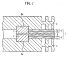
- In the fuel cell, it is desirable to improve the sealing characteristics of the membrane electrode assembly and the separators. For example, Japanese laid-open patent publication No. 2001-319667 discloses a fuel cell directed to improve the sealing characteristics. As shown in FIG. 7, the fuel cell includes a
membrane electrode assembly 1, and first andsecond separators membrane electrode assembly 1 includes ananode 5, and acathode 6, and a solidpolymer electrolyte membrane 4 interposed between theanode 5 and thecathode 6. Theanode 5 includes agas diffusion layer 5a and anelectrode catalyst layer 5b. Thecathode 6 includes a gas diffusion layer 6a and an electrode catalyst layer 6b. The solidpolymer electrolyte membrane 4 has an extension extending outwardly from thecathode 5 and theanode 6. The first andsecond separators grooves polymer electrolyte membrane 4.Liquid seals 7 are provided in thegrooves liquid seals 7 are made of a heat curing fluoride or silicone. Theliquid seals 7 are applied in thegrooves liquid seals 7 have a certain viscosity. In use, theliquid seals 7 are hardened to have a certain elasticity in a solid state. Theliquid seals 7 are tightly in contact with the extension of the solidpolymer electrolyte membrane 4, and end surfaces of thegas diffusion layers 5a, 6a, and theelectrode catalyst layers 5b, 6b. - However, it is difficult to ensure that the
liquid seals 7 provided around thecathode 5 and theanode 6 are tightly in contact with the end surfaces of thegas diffusion layers 5a, 6a, and theelectrode catalyst layers 5b, 6b due to the factor such as the tolerance in producing, and assembling the components. If there is a clearance between theliquid seals 7 and thegas diffusion layers 5a, 6a, the reactant gas may leak into the clearance. Some of the reactant gas such as an oxygen-gas and a fuel gas leaks into the reactant gas discharge passage through the clearance, and is not supplied to electrode surfaces of thecathode 5 and theanode 6. Consequently, the power generation can not be performed efficiently. - Though not illustrated, a coolant for cooling the electrode surface may also leak into a coolant flow field through the clearance around the electrode surface. Since the coolant does not flow along the electrode surface, the electrode surface is not cooled by the coolant efficiently.
- A general object of the present invention is to provide a fuel cell with a simple structure in which a fluid such as a reactant gas does not leak out of a predetermined flow passage, and the desired power generation performance is maintained.
- According to the present invention, an electrolyte electrode assembly includes a pair of electrodes and an electrolyte interposed between the electrodes. Separators sandwich the electrolyte electrode assembly. A reactant gas supply passage and a reactant gas discharge passage extend through the separators in a stacking direction. At least one of the separators has a reactant gas flow field connected between the reactant gas supply passage and the reactant gas discharge passage for supplying a reactant gas to the electrode. A seal member is provided around the electrode for sealing the reactant gas flow field, the reactant gas supply passage, and the reactant gas discharge passage. A filling seal is provided tightly in contact with at least an outer end surface of the electrode for preventing leakage of the reactant gas at an outer region of the electrode.
- In the fuel cell according to the present invention, the reactant gas does not flow through the clearance between the electrode and the seal member. Therefore, the reactant gas is reliably supplied to the surface of the electrode. Thus, the reactant gas is utilized efficiently, and the power generation performance is improved effectively. Further, the present invention is carried out simply by providing the filling seal tightly in contact with at least the electrode. Thus, the fuel cell has a simple structure, and can be produced economically.
- The filling seal may be provided near the reactant gas supply passage and near the reactant gas discharge passage. Thus, sealing is reliably performed near the reactant gas supply passage and the reactant gas discharge passage, i.e., at the positions where leakage of the reactant gas is likely to occur. Leakage of the reactant gas is greatly reduced with the simple structure.
- The reactant gas flow field may include at least one U-Turn region, and the filling seal may be provided near the U-Turn region for preventing leakage of the reactant gas from the U-Turn region. Thus, even if the reactant gas flow field comprises a serpentine reactant gas flow passage, leakage of the reactant gas is reliably prevented with the simple structure.
- At least one of the separators may have a coolant flow field for supplying a coolant to cool the electrode. An additional filling seal may be provided in a part of a clearance between the coolant flow field and the seal member for preventing leakage of the coolant into the clearance.
- The coolant does not flow directly flow from the coolant supply passage to the coolant discharge passage. The coolant flows along the coolant flow field suitably. Thus, the efficiency in cooling the electrode surface is improved with the simple structure, and the power generation is performed economically.
- Preferred embodiments of the invention will now be described by way of example only and with reference to the accompanying drawings in which:
- FIG. 1 is an exploded perspective view showing main components of a fuel cell according to a first embodiment of the present invention;
- FIG. 2 is a cross sectional view showing the main components of the fuel cell;
- FIG. 3 is a front view showing a first separator of the fuel cell;
- FIG. 4 is a front view showing a second separator of the fuel cell;
- FIG. 5 is an exploded perspective view showing main components of a fuel cell according to a second embodiment of the present invention;
- FIG. 6 is a cross sectional view showing the main components of the fuel cell; and
- FIG. 7 is a cross sectional view showing main components of a conventional fuel cell.
- FIG. 1 is an exploded perspective view showing main components of a
fuel cell 10 according to a first embodiment of the present invention. FIG. 2 is a cross sectional view showing the main components of thefuel cell 10. - The
fuel cell 10 includes a membrane electrode assembly (electrolyte electrode assembly) 12, and first andsecond separators membrane electrode assembly 12. As shown in FIG. 1, at one end of thefuel cell 10 in a horizontal direction indicated by an arrow B, an oxygen-containing gas supply passage (reactant gas supply passage) 20a for supplying an oxygen-containing gas, acoolant discharge passage 22b for discharging a coolant, and a fuel gas discharge passage (reactant gas discharge passage) 24b for discharging a fuel gas such as a hydrogen-containing gas are arranged in a vertical direction indicated by an arrow C. The oxygen-containinggas supply passage 20a, thecoolant discharge passage 22b, and the fuelgas discharge passage 24b extend through thefuel cell 10 in a stacking direction indicated by an arrow A. - At the other end of the
fuel cell 10 in the direction indicated by the arrow B, a fuel gas supply passage (reactant gas supply passage) 24a for supplying the fuel gas, acoolant supply passage 22a for supplying the coolant, and an oxygen-containing gas discharge passage (reactant gas discharge passage) 20b for discharging the oxygen-containing gas are arranged in the direction indicated by the arrow C. The fuelgas supply passage 24a, thecoolant supply passage 22a, and the oxygen-containinggas discharge passage 20b extend through thefuel cell 10 in the direction indicated by the arrow A. - The
membrane electrode assembly 12 comprises ananode 28, acathode 30, and a solidpolymer electrolyte membrane 26 interposed between theanode 28 and thecathode 30. The solidpolymer electrolyte membrane 26 is formed by impregnating a thin membrane of perfluorosulfonic acid with water, for example. - As shown in FIG. 2, each of the
anode 28 and thecathode 30 has a gas diffusion layer (porous diffusion member) 32a, 32b, and anelectrode catalyst layer electrode catalyst layer gas diffusion layer electrode catalyst layer 34a of theanode 28 and theelectrode catalyst layer 34b of thecathode 30 are fixed to both surfaces of the solidpolymer electrolyte membrane 26, respectively. - As shown in FIG. 1, the
first separator 14 has an oxygen-containing gas flow field (reactant gas flow field) 36 on itssurface 14a facing themembrane electrode assembly 12. As shown in FIG. 3, the oxygen-containingflow field 36 comprises a plurality of oxygen-containinggas grooves 38 extending in a serpentine pattern including twoU-Turn regions gas grooves 38 of the oxygen-containinggas flow field 36 are connected to the oxygen-containinggas supply passage 20a at one end, and connected to the oxygen-containinggas discharge passage 20b at the other end. - As shown in FIG. 4, the
second separator 16 has a fuel gas flow field (reactant gas flow field) 40 on itsurface 16a facing themembrane electrode assembly 12. The fuelgas flow field 40 comprises a plurality offuel gas grooves 42 extending in a serpentine pattern including twoU-Turn regions fuel gas grooves 42 of the fuelgas flow field 40 is connected to the fuelgas supply passage 24a at one end, and connected to the fuelgas discharge passage 24b at the other end. - As shown in FIGS. 1 and 2, a
coolant flow field 44 is formed between asurface 14b of thefirst separator 14 and asurface 16b of thesecond separator 16. Thecoolant flow field 44 comprises a plurality ofcoolant grooves 46 extending in a serpentine pattern including twoU-Turn regions coolant grooves 46 of thecoolant flow field 44 is connected to thecoolant supply passage 22a at one end, and connected to thecoolant discharge passage 22b at the other end. - As shown in FIGS. 1 through 3, a
seal groove 48 is formed on thesurface 14a of thefirst separator 14 around thecathode 30, i.e., around the oxygen-containinggas flow field 36, the oxygen-containinggas supply passage 20a, and the oxygen-containinggas discharge passage 20b. Aseal member 50 is provided in theseal groove 48. As shown in FIGS. 2 and 3, filling seals 54 are provided at some positions in aclearance 52 between thecathode 30 and theseal member 50 for preventing leakage of the oxygen-containing gas into theclearance 52. The filling seals 54 are tightly in contact with at least the outer end surface of thecathode 30. - The filling seals 54 are liquid seals or solid filling seals, for example. The filling seals 54 are provided at positions where leakage of the oxygen-containing gas is likely to occur. Specifically, the filling seals 54 are provided in the
clearance 52 near the oxygen-containinggas supply passage 20a, near the oxygen-containinggas discharge passage 20b, and near theU-Turn regions - As shown in FIGS. 2 and 4, a
seal groove 56 is formed on thesurface 16a of thesecond separator 16 around theanode 28, i.e., around the fuelgas flow field 40, the fuelgas supply passage 24a, and the fuelgas discharge passage 24b. Aseal member 58 is provided in theseal groove 56. - Filling seals 62 are provided at some positions in a
clearance 60 between theanode 28 and theseal member 58. The filling seals 62 are tightly in contact with at least the outer end surface of theanode 28. As with the filling seals 54, the filling seals 62 are provided at positions where leakage of the fuel gas is likely to occur. Specifically, the filling seals 62 are provided in theclearance 60 near the fuelgas supply passage 24a, near the fuelgas discharge passage 24b, and near theU-Turn regions - As shown in FIG. 1, a
seal groove 64 is formed on thesurface 16b of thesecond separator 16 around thecoolant flow field 44. Aseal member 66 is provided in theseal groove 64. Filling seals 70 are provided at some positions in aclearance 68 between thecoolant flow field 44 and theseal member 66. Specifically, the filling seals 70 are provided in theclearance 68 near thecoolant supply passage 22a, near thecoolant discharge passage 22b, and near theU-Turn regions - Next, operation of the
fuel cell 10 will be described below. As shown in FIG. 1, an oxygen-containing gas is supplied to the oxygen-containinggas supply passage 20a, and a fuel gas such as a hydrogen-containing gas is supplied to the fuelgas supply passage 24a. Further, a coolant such as pure water, an ethylene glycol or an oil is supplied to thecoolant supply passage 22a. - The oxygen-containing gas flows from the oxygen-containing
gas supply passage 20a into the oxygen-containinggas flow field 36 formed on thefirst separator 14, and flows through the oxygen-containinggas grooves 38 in the direction indicated by the arrow B in a serpentine pattern along thecathode 30 of themembrane electrode assembly 12 to induce an electrochemical reaction at thecathode 30. The fuel gas flows from the fuelgas supply passage 24a into the fuelgas flow field 40 formed on thesecond separator 16, and flows through thefuel gas grooves 42 in the direction indicated by the arrow B in a serpentine pattern along theanode 28 of themembrane electrode assembly 12 to induce an electrochemical reaction at theanode 28. - In the
membrane electrode assembly 12, the oxygen-containing gas supplied to thecathode 30, and the fuel gas supplied to theanode 28 are consumed in the electrochemical reactions at the electrode catalyst layers 34a, 34b of thecathode 30 and theanode 28 for generating electricity. - After the oxygen-containing gas is consumed at the
cathode 30, the oxygen-containing gas is discharged into the oxygen-containinggas discharge passage 20b, and flows in the direction indicated by the arrow A. Similarly, after the fuel gas is consumed at theanode 28, the fuel gas is discharged into the fuelgas discharge passage 24b, and flows in the direction indicated by the arrow A. - The coolant flows from the
coolant supply passage 22a into thecoolant flow field 44 between thefirst separator 14 and thesecond separator 16, and flows in the direction indicated by the arrow B in a serpentine pattern. After the coolant is used for cooling themembrane electrode assembly 12, the coolant is discharged into thecoolant discharge passage 22b. - In the first embodiment, as shown in FIGS. 2 and 3, the oxygen-containing
gas flow field 36 comprises a passage of the oxygen-containinggas grooves 38 in the serpentine pattern formed on thesurface 14a of thefirst separator 14, and theseal member 50 is provided in theseal groove 48 around the oxygen-containinggas flow field 36. The filling seals 54 are provided in theclearance 52 between the oxygen-containinggas flow field 36 and theseal member 50, at positions near the oxygen-containinggas supply passage 20a, near the oxygen-containinggas discharge passage 20b, and near theU-turn regions - As described above, the filling seals 54 are provided at positions where leakage of the oxygen-containing gas into the
clearance 52 is likely to occur. Therefore, the oxygen-containing gas does not flow along theclearance 52, and the oxygen-containing gas is reliably supplied to the electrode surface of thecathode 30. Since the oxygen-containing gas does not flow into the oxygen-containinggas discharge passage 20b through theclearance 52 around thecathode 30, the oxygen-containing gas can be utilized efficiently, and the power generation performance is improved effectively. - The first embodiment of the present invention can be carried out simply by providing the filling seals 54 at positions where leakage of the oxygen-containing gas into the
clearance 52 is likely to occur. Thus, thefirst separator 14 has a simple structure, and can be produced at a low cost. - As shown in FIGS. 2 and 4, as with the oxygen-containing
gas flow field 36, the fuelgas flow field 40 comprises a passage of thefuel gas grooves 42 in the serpentine pattern formed on thesurface 16a of thesecond separator 16, and theseal member 58 is provided in theseal groove 48 around the fuelgas flow field 40. Further, the filling seals 62 are provided at positions where leakage of the fuel gas into theclearance 60 is likely to occur. - Therefore, the fuel gas does not leak through the
gas diffusion layer 32a into theclearance 60, and does not flow into the fuelgas discharge passage 24b through theclearance 60. The fuel gas is utilized efficiently, and the power generation performance can be improved effectively. Thesecond separator 16 has the advantage as with thefirst separator 14. - Further, as shown in FIG. 1, the
coolant flow field 44 comprises a passage of thecoolant grooves 46 in the serpentine pattern formed on thesurface 16b of thesecond separator 16. Theseal member 66 is provided around thecoolant flow field 44. The filling seals 70 are provided in theclearance 68 between theseal member 66 and thecoolant flow field 44 at positions where leakage of the coolant is likely to occur. - Thus, the coolant does not leak into the
clearance 68, and flows along thecoolant flow field 44 desirably. Consequently, the electrode surfaces of themembrane electrode assembly 12 can be cooled by the coolant efficiently. - FIG. 5 is an exploded perspective view showing main components of a
fuel cell 80 according to a second embodiment of the present invention, and FIG. 6 is a cross sectional view showing the main components of thefuel cell 80. The constituent elements that are identical to those of thefuel cell 10 according to the first embodiment are labeled with the same reference numeral, and description thereof is omitted. - The
fuel cell 80 includes a membrane electrode assembly (electrolyte electrode assembly) 82, and first andsecond metal separators membrane electrode assembly 82. Theelectrolyte electrode assembly 82 includes ananode 88, acathode 90, and a solidpolymer electrolyte membrane 26 interposed between theanode 88 and thecathode 90. The surface area of theanode 88 is larger than the surface area of thecathode 90. Thegas diffusion layer 32a of theanode 88 includes an outermarginal region 85 extending outwardly beyond an outer region of thegas diffusion layer 32b of thecathode 90. - As shown in FIG. 6, a
seal member 92 is provided on thefirst metal separator 84. Theseal member 92 may be attached to thefirst metal separator 84 by heat. Theseal member 92 includes amain seal 94 interposed between the solidpolymer electrolyte membrane 26 and thefirst separator 84, corresponding to a position of the outermarginal region 85 of thegas diffusion layer 32a of theanode 88. Further, theseal member 92 includes aflow field wall 96 interposed between the outer region of thegas diffusion layer 32b and thefirst metal separator 84. - As shown in FIGS. 5 and 6, filling
seals 100 are provided at some positions in aclearance 99 between theseal member 92 and end surfaces of thegas diffusion layer 32b and theelectrode catalyst layer 34b of thecathode 90. The filling seals 100 prevent leakage of the oxygen-containing gas into theclearance 99. For example, the filling seals are liquid seals or solid filling seals. The filling seals 100 are provided in theclearance 99 at positions where leakage of the oxygen-containing gas is likely to occur, for example, near the oxygen-containinggas supply passage 20a, near the oxygen-containinggas discharge passage 20b, and near theU-turn regions - As shown in FIGS. 5 and 6, a
coolant flow field 102 is formed between the first andsecond metal separators coolant flow field 102 comprises a plurality ofcoolant grooves 104 extending between thecoolant supply passage 22a and thecoolant discharge passage 22b in the direction indicated by the arrow B.A seal member 106 is inserted between thefirst metal separator 84 and thesecond metal separator 86 at a position corresponding to themain seal 94 of theseal member 92. Thecoolant flow field 102 is sealed air-tight by theseal member 106. Thecoolant grooves 104 of thecoolant flow field 102 is connected to thecoolant supply passage 22a at one end, and connected to thecoolant discharge passage 22b at the other end inside theseal member 106. - In the second embodiment, the filling
seals 100 are provided in theclearance 99 between theseal member 92 and the end surfaces of thegas diffusion layer 32b and theelectrode catalyst layer 34b of thecathode 90 at positions near the oxygen-containinggas supply passage 20a, near the oxygen-containinggas discharge passage 20b, and near theU-Turn regions gas diffusion layer 32b of thecathode 90. Thus, the reactant gas is utilized efficiently, and the power generation performance is improved effectively as with the first embodiment. - In the fuel cell according to the present invention, the reactant gas does not flow through the clearance between the electrode and the seal member. Therefore, the reactant gas is reliably supplied to the surface of the electrode. Thus, the reactant gas is utilized efficiently, and the power generation performance is improved effectively. Further, the present invention is carried out simply by providing the filling seal tightly in contact with at least the electrode. Thus, the fuel cell has a simple structure, and can be produced economically.
Claims (8)
- A fuel cell comprising:an electrolyte electrode assembly (12) including a pair of electrodes (28, 30) and an electrolyte (26) interposed between said electrodes (28, 30);separators (14, 16) for sandwiching said electrolyte electrode assembly (12), a reactant gas supply passage (20a) and a reactant gas discharge passage (20b) extending through said separators (14, 16) in a stacking direction, at least one of said separators (14) having a reactant gas flow field (36) connected between said reactant gas supply passage (20a) and said reactant gas discharge passage (20b) for supplying a reactant gas to said electrode (30);a seal member (50) provided around said electrode (30) for sealing said reactant gas flow field (36), said reactant gas supply passage (20a), and said reactant gas discharge passage (20b); anda filling seal (54) provided tightly in contact with at least an outer end surface of said electrode (30) for preventing leakage of said reactant gas at an outer region of said electrode (30).
- A fuel cell as claimed in claim 1, wherein said filling seal (54) is provided near said reactant gas supply passage (20a) and near said reactant gas discharge passage (20b).
- A fuel cell as claimed in claim 1 or 2, wherein said reactant gas flow field (36) includes at least one U-Turn region (36a), and said filling seal (54) is provided near said U-Turn region (36a) for preventing leakage of said reactant gas from said U-Turn region (36a).
- A fuel cell as claimed in claim 1, 2 or 3, wherein a seal groove (48) is formed around said reactant gas flow field (36), said reactant gas supply passage (20a), and said reactant gas discharge passage (20b);
said seal member (50) is provided in said seal groove (48); and
said filling seal (54) is provided in a part of a clearance (68) between said seal member (50) and said outer end surface of said electrode (30). - A fuel cell as claimed in any preceding claim, wherein at least one of said separators (16) has a coolant flow field (44) for supplying a coolant to cool said electrode (28);
an additional filling seal (70) is provided in a part of a clearance (68) between said coolant flow field (44) and said seal member (66) for preventing leakage of said coolant into said clearance (68). - A fuel cell as claimed in claim 5, wherein a coolant supply passage (22a) and a coolant discharge passage (22b) extend through said separators (14, 16) in said stacking direction; and
said additional filling seal (70) is provided near said coolant supply passage (22a), and near said coolant discharge passage (22b). - A fuel cell as claimed in claim 5 or 6, wherein said coolant flow field (44) includes at least one U-Turn region (44a), and said additional filling seal (70) is provided near said U-Turn region (44a) for preventing leakage of said reactant gas from said U-Turn region (44a).
- A fuel cell as claimed in claim 6 or 7, wherein a seal groove (64) is formed around said coolant flow field (44), said coolant supply passage (22a), and said coolant discharge passage (22b), and said seal member (66) is provided in said seal groove (64).
Applications Claiming Priority (2)
| Application Number | Priority Date | Filing Date | Title |
|---|---|---|---|
| JP2002279203 | 2002-09-25 | ||
| JP2002279203A JP4067371B2 (en) | 2002-09-25 | 2002-09-25 | Fuel cell |
Publications (3)
| Publication Number | Publication Date |
|---|---|
| EP1403951A2 true EP1403951A2 (en) | 2004-03-31 |
| EP1403951A3 EP1403951A3 (en) | 2007-01-10 |
| EP1403951B1 EP1403951B1 (en) | 2014-07-02 |
Family
ID=31973277
Family Applications (1)
| Application Number | Title | Priority Date | Filing Date |
|---|---|---|---|
| EP03256048.4A Expired - Lifetime EP1403951B1 (en) | 2002-09-25 | 2003-09-25 | Fuel cell seals |
Country Status (4)
| Country | Link |
|---|---|
| US (1) | US7326485B2 (en) |
| EP (1) | EP1403951B1 (en) |
| JP (1) | JP4067371B2 (en) |
| CA (1) | CA2442436C (en) |
Cited By (5)
| Publication number | Priority date | Publication date | Assignee | Title |
|---|---|---|---|---|
| WO2008006435A1 (en) * | 2006-07-12 | 2008-01-17 | Carl Freudenberg Kg | Module for a fuel cell arrangement |
| WO2008070468A2 (en) * | 2006-12-06 | 2008-06-12 | 3M Innovative Properties Company | Compact fuel cell stack with uniform depth flow fields |
| US7740962B2 (en) | 2006-12-06 | 2010-06-22 | 3M Innovative Properties Company | Compact fuel cell stack with current shunt |
| US9312548B2 (en) | 2011-03-15 | 2016-04-12 | Audi Ag | Fuel cell plate bonding method and arrangement |
| US10340533B2 (en) | 2015-07-17 | 2019-07-02 | Nissan Motor Co., Ltd. | Fuel cell stack |
Families Citing this family (24)
| Publication number | Priority date | Publication date | Assignee | Title |
|---|---|---|---|---|
| JP4189345B2 (en) * | 2004-03-24 | 2008-12-03 | 本田技研工業株式会社 | Fuel cell |
| WO2006040994A1 (en) * | 2004-10-08 | 2006-04-20 | Matsushita Electric Industrial Co., Ltd. | Mea-gasket assembly and polymer electrolytic fuel cell employing same |
| US8278007B2 (en) | 2004-12-28 | 2012-10-02 | Panasonic Corporation | Fuel cell and fuel cell stack comprising the same |
| JP2006269264A (en) * | 2005-03-24 | 2006-10-05 | Fuji Electric Holdings Co Ltd | Solid polyelectrolyte fuel cell |
| JP5079507B2 (en) | 2005-07-13 | 2012-11-21 | パナソニック株式会社 | Polymer electrolyte fuel cell and fuel cell seal member used therefor |
| WO2007013298A1 (en) | 2005-07-27 | 2007-02-01 | Matsushita Electric Industrial Co., Ltd. | Fuel cell |
| JP2007059330A (en) * | 2005-08-26 | 2007-03-08 | Mitsubishi Electric Corp | Solid polymer fuel cell |
| JP4940655B2 (en) * | 2005-12-27 | 2012-05-30 | トヨタ自動車株式会社 | Fuel cell |
| JP4960647B2 (en) * | 2006-04-06 | 2012-06-27 | Nok株式会社 | FUEL CELL, SEPARATOR, AND METHOD FOR PRODUCING THE SAME |
| JP5087863B2 (en) | 2006-06-09 | 2012-12-05 | トヨタ自動車株式会社 | Fuel cell |
| JP4978881B2 (en) | 2006-06-26 | 2012-07-18 | トヨタ自動車株式会社 | Fuel cell |
| US20080138665A1 (en) * | 2006-12-06 | 2008-06-12 | 3M Innovative Properties Company | Compact fuel cell stack with gas ports |
| US20080138667A1 (en) * | 2006-12-06 | 2008-06-12 | 3M Innovative Properties Company | Compact fuel cell stack with fastening member |
| JP5103934B2 (en) * | 2007-02-21 | 2012-12-19 | トヨタ自動車株式会社 | Fuel cell manufacturing method and fuel cell |
| JP5162925B2 (en) * | 2007-03-05 | 2013-03-13 | トヨタ自動車株式会社 | Manufacturing method of fuel cell module and manufacturing method of fuel cell |
| JP5180513B2 (en) * | 2007-05-14 | 2013-04-10 | 本田技研工業株式会社 | Fuel cell |
| US7914938B2 (en) * | 2007-06-09 | 2011-03-29 | National Tsing Hua University | Flat fuel cell combining a runner plate and conducting layer |
| JP5309574B2 (en) * | 2008-01-22 | 2013-10-09 | トヨタ自動車株式会社 | Fuel cell |
| US8986905B2 (en) * | 2008-11-11 | 2015-03-24 | Bloom Energy Corporation | Fuel cell interconnect |
| KR101230090B1 (en) * | 2010-06-21 | 2013-02-05 | 한국과학기술원 | Fuel-cell of fixing a cell with sealing material and the method for manufacturing the same |
| JP5734823B2 (en) * | 2011-12-13 | 2015-06-17 | 本田技研工業株式会社 | Fuel cell stack |
| US9478812B1 (en) * | 2012-10-17 | 2016-10-25 | Bloom Energy Corporation | Interconnect for fuel cell stack |
| WO2014074478A1 (en) | 2012-11-06 | 2014-05-15 | Bloom Energy Corporation | Improved interconnect and end plate design for fuel cell stack |
| DE202018105617U1 (en) * | 2018-09-28 | 2020-01-03 | Reinz-Dichtungs-Gmbh | Separator plate and electrochemical system |
Citations (2)
| Publication number | Priority date | Publication date | Assignee | Title |
|---|---|---|---|---|
| GB2323700A (en) | 1997-03-29 | 1998-09-30 | Ballard Power Systems | Electrochemical cells |
| JP2000323156A (en) | 1999-05-13 | 2000-11-24 | Mitsubishi Plastics Ind Ltd | Solid polymer type fuel cell |
Family Cites Families (10)
| Publication number | Priority date | Publication date | Assignee | Title |
|---|---|---|---|---|
| JP3648128B2 (en) | 2000-05-02 | 2005-05-18 | 本田技研工業株式会社 | Fuel cell |
| JP4401554B2 (en) * | 2000-09-04 | 2010-01-20 | 本田技研工業株式会社 | Fuel cell |
| JP4969719B2 (en) | 2000-10-17 | 2012-07-04 | 本田技研工業株式会社 | Fuel cell |
| JP3609016B2 (en) * | 2000-10-18 | 2005-01-12 | 本田技研工業株式会社 | Fuel cell seal mounting method and fuel cell |
| US6946210B2 (en) | 2000-11-27 | 2005-09-20 | Protonex Technology Corporation | Electrochemical polymer electrolyte membrane cell stacks and manufacturing methods thereof |
| FR2819343B1 (en) | 2001-01-10 | 2003-04-04 | Technicatome | FUEL CELL HAVING IDENTICAL POLAR PLATES AND INTERNAL CIRCULATION OF FUEL AND REFRIGERANT |
| JP4776787B2 (en) * | 2001-01-30 | 2011-09-21 | 本田技研工業株式会社 | Fuel cell and manufacturing method thereof |
| WO2002063706A1 (en) | 2001-02-07 | 2002-08-15 | Siemens Aktiengesellschaft | Fuel cells |
| US6605380B2 (en) | 2001-02-27 | 2003-08-12 | Dana Corporation | Fuel cell plate with variable thickness sealing beads |
| JP5208338B2 (en) * | 2001-06-29 | 2013-06-12 | 本田技研工業株式会社 | Electrolyte membrane / electrode structure and fuel cell |
-
2002
- 2002-09-25 JP JP2002279203A patent/JP4067371B2/en not_active Expired - Fee Related
-
2003
- 2003-09-24 CA CA2442436A patent/CA2442436C/en not_active Expired - Fee Related
- 2003-09-25 US US10/672,672 patent/US7326485B2/en active Active
- 2003-09-25 EP EP03256048.4A patent/EP1403951B1/en not_active Expired - Lifetime
Patent Citations (2)
| Publication number | Priority date | Publication date | Assignee | Title |
|---|---|---|---|---|
| GB2323700A (en) | 1997-03-29 | 1998-09-30 | Ballard Power Systems | Electrochemical cells |
| JP2000323156A (en) | 1999-05-13 | 2000-11-24 | Mitsubishi Plastics Ind Ltd | Solid polymer type fuel cell |
Cited By (7)
| Publication number | Priority date | Publication date | Assignee | Title |
|---|---|---|---|---|
| WO2008006435A1 (en) * | 2006-07-12 | 2008-01-17 | Carl Freudenberg Kg | Module for a fuel cell arrangement |
| US8105725B2 (en) | 2006-07-12 | 2012-01-31 | Carl Freudenberg Kg | Module for a fuel cell arrangement |
| WO2008070468A2 (en) * | 2006-12-06 | 2008-06-12 | 3M Innovative Properties Company | Compact fuel cell stack with uniform depth flow fields |
| WO2008070468A3 (en) * | 2006-12-06 | 2008-08-21 | 3M Innovative Properties Co | Compact fuel cell stack with uniform depth flow fields |
| US7740962B2 (en) | 2006-12-06 | 2010-06-22 | 3M Innovative Properties Company | Compact fuel cell stack with current shunt |
| US9312548B2 (en) | 2011-03-15 | 2016-04-12 | Audi Ag | Fuel cell plate bonding method and arrangement |
| US10340533B2 (en) | 2015-07-17 | 2019-07-02 | Nissan Motor Co., Ltd. | Fuel cell stack |
Also Published As
| Publication number | Publication date |
|---|---|
| CA2442436C (en) | 2011-03-01 |
| CA2442436A1 (en) | 2004-03-25 |
| EP1403951B1 (en) | 2014-07-02 |
| US7326485B2 (en) | 2008-02-05 |
| EP1403951A3 (en) | 2007-01-10 |
| US20040115509A1 (en) | 2004-06-17 |
| JP4067371B2 (en) | 2008-03-26 |
| JP2004119121A (en) | 2004-04-15 |
Similar Documents
| Publication | Publication Date | Title |
|---|---|---|
| CA2442436C (en) | Fuel cell | |
| US7799480B2 (en) | Fuel cell stack with dummy cell | |
| US7309542B2 (en) | Membrane electrode assembly and fuel cell | |
| US7799482B2 (en) | Stack of generators and fuel cell system having the same | |
| CA2522479C (en) | Fuel cell stack | |
| US7759014B2 (en) | Fuel cell having a seal member | |
| CA2446540C (en) | Fuel cell stack with electrically conductive corrugated heat insulation plate | |
| US20050186464A1 (en) | Fuel cell | |
| US7977003B2 (en) | Fuel cell | |
| US8415068B2 (en) | Fuel cell | |
| US20060024561A1 (en) | Fuel cell stack | |
| CA2490011C (en) | Fuel cell with separator having a ridge member | |
| US7572538B2 (en) | Fuel cell | |
| US7393607B2 (en) | Fuel cell and fuel cell stack | |
| US8192894B2 (en) | Plate-laminating type fuel cell | |
| US11811104B2 (en) | Bipolar plate with undulating channels | |
| JP3866246B2 (en) | Fuel cell | |
| JPH06333582A (en) | Solid polyelectrolyte fuel cell | |
| CN116895776A (en) | Separator for fuel cell and power generation cell | |
| JP2005294169A (en) | Fuel cell |
Legal Events
| Date | Code | Title | Description |
|---|---|---|---|
| PUAI | Public reference made under article 153(3) epc to a published international application that has entered the european phase |
Free format text: ORIGINAL CODE: 0009012 |
|
| AK | Designated contracting states |
Kind code of ref document: A2 Designated state(s): AT BE BG CH CY CZ DE DK EE ES FI FR GB GR HU IE IT LI LU MC NL PT RO SE SI SK TR |
|
| AX | Request for extension of the european patent |
Extension state: AL LT LV MK |
|
| PUAL | Search report despatched |
Free format text: ORIGINAL CODE: 0009013 |
|
| AK | Designated contracting states |
Kind code of ref document: A3 Designated state(s): AT BE BG CH CY CZ DE DK EE ES FI FR GB GR HU IE IT LI LU MC NL PT RO SE SI SK TR |
|
| AX | Request for extension of the european patent |
Extension state: AL LT LV MK |
|
| 17P | Request for examination filed |
Effective date: 20070213 |
|
| AKX | Designation fees paid |
Designated state(s): DE GB |
|
| 17Q | First examination report despatched |
Effective date: 20080623 |
|
| RIC1 | Information provided on ipc code assigned before grant |
Ipc: H01M 8/24 20060101AFI20131219BHEP Ipc: H01M 8/10 20060101ALN20131219BHEP Ipc: H01M 8/02 20060101ALI20131219BHEP |
|
| GRAP | Despatch of communication of intention to grant a patent |
Free format text: ORIGINAL CODE: EPIDOSNIGR1 |
|
| INTG | Intention to grant announced |
Effective date: 20140210 |
|
| RIC1 | Information provided on ipc code assigned before grant |
Ipc: H01M 8/24 20060101ALN20140131BHEP Ipc: H01M 8/02 20060101AFI20140131BHEP Ipc: H01M 8/10 20060101ALN20140131BHEP |
|
| RIN1 | Information on inventor provided before grant (corrected) |
Inventor name: MOHRI, MASAHIRO Inventor name: SUGITA, NARUTOSHI Inventor name: YOSHIDA, HIROMICHI Inventor name: WACHI, DAISUKE Inventor name: GOTO, SHUHEI Inventor name: FUJII, YOSUKE |
|
| GRAS | Grant fee paid |
Free format text: ORIGINAL CODE: EPIDOSNIGR3 |
|
| GRAA | (expected) grant |
Free format text: ORIGINAL CODE: 0009210 |
|
| AK | Designated contracting states |
Kind code of ref document: B1 Designated state(s): DE GB |
|
| REG | Reference to a national code |
Ref country code: GB Ref legal event code: FG4D |
|
| REG | Reference to a national code |
Ref country code: DE Ref legal event code: R096 Ref document number: 60346418 Country of ref document: DE Effective date: 20140814 |
|
| REG | Reference to a national code |
Ref country code: DE Ref legal event code: R097 Ref document number: 60346418 Country of ref document: DE |
|
| REG | Reference to a national code |
Ref country code: DE Ref legal event code: R084 Ref document number: 60346418 Country of ref document: DE |
|
| PLBE | No opposition filed within time limit |
Free format text: ORIGINAL CODE: 0009261 |
|
| STAA | Information on the status of an ep patent application or granted ep patent |
Free format text: STATUS: NO OPPOSITION FILED WITHIN TIME LIMIT |
|
| REG | Reference to a national code |
Ref country code: GB Ref legal event code: 746 Effective date: 20150507 |
|
| 26N | No opposition filed |
Effective date: 20150407 |
|
| REG | Reference to a national code |
Ref country code: DE Ref legal event code: R084 Ref document number: 60346418 Country of ref document: DE Effective date: 20150505 |
|
| PGFP | Annual fee paid to national office [announced via postgrant information from national office to epo] |
Ref country code: GB Payment date: 20200916 Year of fee payment: 18 Ref country code: DE Payment date: 20200916 Year of fee payment: 18 |
|
| REG | Reference to a national code |
Ref country code: DE Ref legal event code: R082 Ref document number: 60346418 Country of ref document: DE |
|
| REG | Reference to a national code |
Ref country code: DE Ref legal event code: R119 Ref document number: 60346418 Country of ref document: DE |
|
| GBPC | Gb: european patent ceased through non-payment of renewal fee |
Effective date: 20210925 |
|
| PG25 | Lapsed in a contracting state [announced via postgrant information from national office to epo] |
Ref country code: GB Free format text: LAPSE BECAUSE OF NON-PAYMENT OF DUE FEES Effective date: 20210925 Ref country code: DE Free format text: LAPSE BECAUSE OF NON-PAYMENT OF DUE FEES Effective date: 20220401 |