EP1403630A2 - Vorrichtung zur Auswertung der Widerstandsfähigkeit von Konstruktionselementen und ästhetischen Elementen gegenüber mechanischen Schäden und Verwendung der Vorrichtung - Google Patents
Vorrichtung zur Auswertung der Widerstandsfähigkeit von Konstruktionselementen und ästhetischen Elementen gegenüber mechanischen Schäden und Verwendung der Vorrichtung Download PDFInfo
- Publication number
- EP1403630A2 EP1403630A2 EP03425633A EP03425633A EP1403630A2 EP 1403630 A2 EP1403630 A2 EP 1403630A2 EP 03425633 A EP03425633 A EP 03425633A EP 03425633 A EP03425633 A EP 03425633A EP 1403630 A2 EP1403630 A2 EP 1403630A2
- Authority
- EP
- European Patent Office
- Prior art keywords
- test
- test tool
- tract
- impact
- tool
- Prior art date
- Legal status (The legal status is an assumption and is not a legal conclusion. Google has not performed a legal analysis and makes no representation as to the accuracy of the status listed.)
- Granted
Links
Images



Classifications
-
- G—PHYSICS
- G01—MEASURING; TESTING
- G01N—INVESTIGATING OR ANALYSING MATERIALS BY DETERMINING THEIR CHEMICAL OR PHYSICAL PROPERTIES
- G01N3/00—Investigating strength properties of solid materials by application of mechanical stress
- G01N3/30—Investigating strength properties of solid materials by application of mechanical stress by applying a single impulsive force, e.g. by falling weight
- G01N3/307—Investigating strength properties of solid materials by application of mechanical stress by applying a single impulsive force, e.g. by falling weight generated by a compressed or tensile-stressed spring; generated by pneumatic or hydraulic means
-
- G—PHYSICS
- G01—MEASURING; TESTING
- G01N—INVESTIGATING OR ANALYSING MATERIALS BY DETERMINING THEIR CHEMICAL OR PHYSICAL PROPERTIES
- G01N3/00—Investigating strength properties of solid materials by application of mechanical stress
- G01N3/56—Investigating resistance to wear or abrasion
-
- G—PHYSICS
- G01—MEASURING; TESTING
- G01N—INVESTIGATING OR ANALYSING MATERIALS BY DETERMINING THEIR CHEMICAL OR PHYSICAL PROPERTIES
- G01N2203/00—Investigating strength properties of solid materials by application of mechanical stress
- G01N2203/0001—Type of application of the stress
- G01N2203/001—Impulsive
-
- G—PHYSICS
- G01—MEASURING; TESTING
- G01N—INVESTIGATING OR ANALYSING MATERIALS BY DETERMINING THEIR CHEMICAL OR PHYSICAL PROPERTIES
- G01N2203/00—Investigating strength properties of solid materials by application of mechanical stress
- G01N2203/0014—Type of force applied
- G01N2203/0016—Tensile or compressive
- G01N2203/0019—Compressive
-
- G—PHYSICS
- G01—MEASURING; TESTING
- G01N—INVESTIGATING OR ANALYSING MATERIALS BY DETERMINING THEIR CHEMICAL OR PHYSICAL PROPERTIES
- G01N2203/00—Investigating strength properties of solid materials by application of mechanical stress
- G01N2203/003—Generation of the force
- G01N2203/0053—Cutting or drilling tools
-
- G—PHYSICS
- G01—MEASURING; TESTING
- G01N—INVESTIGATING OR ANALYSING MATERIALS BY DETERMINING THEIR CHEMICAL OR PHYSICAL PROPERTIES
- G01N2203/00—Investigating strength properties of solid materials by application of mechanical stress
- G01N2203/02—Details not specific for a particular testing method
- G01N2203/022—Environment of the test
- G01N2203/0244—Tests performed "in situ" or after "in situ" use
- G01N2203/0246—Special simulation of "in situ" conditions, scale models or dummies
Definitions
- the present invention relates to a device for evaluating the resistance to the formation of mechanical damages, caused by impacting operating means and tools of various type in structural and aesthetical members, for example damages such as perforations, dents and scratches caused by excavating buckets in structural members such as underground or underwater pipelines.
- the present invention further relates to a method for using the device mentioned above for evaluating the resistance to the impact of structural members, for example pipelines even possibly under pressure, and aesthetical members, for example continuous façades of buildings.
- members with huge sizes usually made of metal, prestressed concrete, reinforced cement and the like, which carry out a static structural role, are meant under structural members.
- structural members For example, it is possible mentioning infrastructure parts, frames, buried, immerged or not ducts, platforms, stocking or landing floors, containers, keels and the like.
- members with medium/huge sizes usually made of glass, plastic, composite material, metal, concrete and the like, which do not carry out a static structural role, but which must be able to stand exceptional impacts or stresses, are meant under aesthetical members.
- infrastructure parts, frames, continuous façades of buildings/ships/airplanes, deadening panels and the like are possible.
- This type of members can be bulky and/or placed in a scarcely controllable position, in particular, for example as it is buried or it is in a hardly accessible position, and therefore they are potentially subjected to accidents wherein an outer operating body (for example operating machine, a ship's anchor, etc) damages the member in question.
- an outer operating body for example operating machine, a ship's anchor, etc
- a tool such as a bucket's tooth, a perforator, a milling machine or a blade could strike a duct, a supporting member or the like, causing a perforation, a dent or a scratch which could diminish the member capability of playing its own structural function.
- the structural member itself could strike a fixed hinder, a sharpened one in case, such as for example a rock.
- results of such tests are of primary importance for: 1) determining the capability of a preestablished excavator in damaging a given gas-pressurized duct; and 2) providing a numeric model of analytical evaluation of the damage.
- This example can be easily transferred to other fields and to other types of damages.
- the technical problem underlying the present invention is to provide an evaluation device allowing to obviate to the drawbacks mentioned with reference to the known art, allowing to obtain concrete and numerous data upon the damages typical for structural and aesthetical members for which one wants to have at disposition also models for foreseeing the effects of said damages.
- a device for evaluating the resistance to formation of mechanical damages comprising:
- the main advantage of the device according to the present invention lies in the possibility of performing tests with force (both static and dynamic), impact direction and tool features variable upon a wide range of possible impacting objects and of structural and aesthetical members subjected to impact.
- the device and the use thereof allow obtaining the parameters useful to foresee the in situ behaviour of the pipeline itself in case of mechanical damages caused by excavators.
- a device for evaluating tracts of pipeline under pressure, intended to be buried is described.
- the tool therefor this example has been devised is the tooth of an excavating bucket.
- any object able to cause a mechanical damage in any structural member for example, drills, buckets without teeth, milling machines or mechanical plows, blades, stones will be meant.
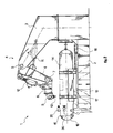
- a device for evaluating the resistance to formation of mechanical damages is designated as a whole with 1.
- a base 2 thereto a first fixed member 3 is fastened, with an articulated mechanical arm 4 which comprises, at the end of the first member 3 opposite to the base 2, a first hinge 5 connected to a second revolving member 6 in turn equipped with a second hinge 7 connected to a third revolving member 8.
- the articulated mechanical arm 4 is movable on a working plane, identifiable in the plane of figure 2.
- the third member 8 is connected to a tool-holding striking head 9 which will be described in greater detail hereinafter, supporting a test tool 10.
- the proposed device comprises first means 11, 12 for driving the articulated mechanical arm 4 to move the test tool 10 in a direction with axial component lying on said working plane, with a predetermined force.
- the first means for driving 11 and 12 comprise two oleodynamic actuators controlled by two electrohydraulic servo controls in closed loop placed in feedback on the position.
- Such actuating means is placed, the first one 11 between the first fixed member 3 and the second revolving member 6, and the second extensible actuator 12, placed between the second revolving member 6 and the third revolving member 8.
- the two actuators can be controlled simultaneously and therefore they can reproduce a composite trajectory by describing the motion of an excavator's articulated arm.
- the base 2 instead, comprises a revolving supporting table 13, supporting a member tract 14, which is fastened to the table 13 by means of a saddle-like structure 17 which fastens it in a transversal and longitudinal way, in order to simulate for example an underground pipe.
- the saddle-like structure 17, constructed with U-shaped members will have to be particularly sized depending upon the test member. It will comprise elastomeric supports, not shown, to reproduce the resting conditions in optimum way.
- the supporting table 14 could be planned to receive and firmly secure any type of structural or aesthetical member.
- the pipe tract 14 comprises at its own ends respective ferrules 15 supporting closing bottoms 16 so as to seal the pipe tract 14.
- the device 1 comprises a first pressurizing central unit, of conventional type and not shown, able to confer to the fluid contained inside the pipe tract 14 a pressure appropriate for carrying out the test, for example 10 MPa.
- a pressure appropriate for carrying out the test for example 10 MPa.
- Such fluid can be an incompressible fluid so as make clearly visible possible leaks, that is simple water.
- the pressurizing central unit and the means mentioned above for sealing the tube tract 14 represent means for pressurizing the tube tract 14.
- the device 1 comprises second means for driving placed between the base 2 and the supporting table 13, so as to make the table able to rotate in a predetermined position, characterized by a precise angulation chosen in advance to perform the test, to simulate the angle between the impacting arm and the test member.
- Said second means for driving comprises a third oleodynamic actuator 18 to move horizontally the support table 13 and therefore the test tool.
- Said actuator is connected to a second pressurizing central unit.
- the striking head 9 is described.
- Such device is provided to be interplaced between the articulated arm 4 and a transducer-holding head 19 thereto the test tool 10 is physically fastened.
- the striking head 9 is constructed so as to allow simulating, in case of misaligned impact, with respect to the upper generator of the test tool tract 14, the transversal shifting of the test tool 10 and due, for example, to the excavator's compliance.
- the system is equipped with inserted guides made of carbonised and rectified steel, with roller-recirculating pads, which allow the transversal sliding of the striking head 9 with respect to the arm 4 minimizing the friction.
- the movement is opposed by four groups of springs 20, so as to implement a stiffness for example comparable to the maximum transversal stiffness experimentally found on the excavators.
- the possibility of eliminating two of the four groups of springs is also provided, in order to implement a stiffness equal to half of the maximum one.
- the initial misalignment can be adjusted from 0 to 150 mm.
- the maximum stroke is equal to 275 mm, for a final maximum misalignment of 425 mm.
- an initial stroke is implemented without increasing the transversal reaction force, in order to simulate the recovery of the backlashes in the couplings of the excavator's arms.
- the transversal force can be adjusted in the range 5 ⁇ 15 kN.
- the test tool 10 has a structure so as to imitate the damage caused by an excavator's bucket, it could be a real bucket tooth.
- the load which causes the damage of the member 14 will thus be applied, according to the present embodiment, by means of said bucket tooth.
- the applied dynamic or static load is measured by means of a force transducer able to detect the force applied according to 3 orthogonal components; such transducer is positioned between the transducer-holding head 19 and the impacting member 10.
- the transducer-holding head 19 is of the type which can be manually adjusted at the beginning of the test by setting the keying angle of the impacting member 10.
- the evaluation device 1 comprises means for adjusting the direction and the force with which the device inflicts blows to the tract of the test member 14, said means being designated as a whole with 21 (figure 4).
- Said adjusting means 21 comprises a calculation unit 22 wherein the parameters are inserted, according to which the test tool 10 has to be moved, that is a motion law x(t), z(t) on the plane x, z, designated with 23, whereon the articulated mechanical arm 4 lies.
- the calculation unit 22 transforms the motion rule 23 of the tool 10 into an operating rule of said first means for driving, that is into operating functions a(t), b(t) 25 for the respective servo commands 11, 12.
- the head By acting properly on the springs 20 and on the backlash and on the intensity of the pad brakes existing on the impacting head 9, the head has the possibility of moving in the plane transversal to the impacting plane (plane containing the actuators 11 and 12) implementing a trajectory/rotation in the space.
- Said operating functions 25 are transferred into a digital servo-controlling unit 26 which, by means of specific drivers 27, transmits said functions to the servo cylinders 30, 31 powered and controlled by the respective servo valves 28, 29.
- the set of servo cylinders 30 and 31 and of the respective servo valves constitutes the first means for driving 11 and 12 mentioned above.
- the above-mentioned transducer of the transducer-holding head 19 is constituted by a load cell 32 able to detect along the three directions, by means of appropriate dynamometric sensors the values of the force associated to said blow, which values, translated by a specific software 33 and by means of an appropriate amplifier 34, are transferred to said servo-controlling unit 26 with a double purpose: displaying and recording the forces and the positions important for the ongoing test and providing feedback signals to simulate correctly the stiffness of the impacting member by means of limitations to the applied force.
- the device 1 comprises means for evaluating the impact between test tool 10 and surface of the member tract 14 involved by the contact.
- Such evaluation means can comprise a videocamera 35 positioned near the member tract 14 (figure 2), for example of the type with high recording speed, to be able to observe the impact, and a three-dimensional detection device, for example of the laser type, able to record the profile of the member damaged after the impact, preferably with a precision of 0,05 mm.
- Each of the preceding movements will have to provide locking devices, not shown, so as to guarantee the position set for the whole test duration.
- the working area will be positioned upon the support table 13 so as to reproduce the real impact conditions.
- the maximum speed of the impacting head will be 5 m/s.
- the slant of the vector speed versus the z-axis will be in the range between 0 and 85°.
- the maximum static force which the system has to be able to generate in the tooth-pipe contact is 300 kN in the z-direction and 200 kN in the x-direction.
- the exerted force could be even greater and it will depend upon the value of the impact speed and upon the possible utilized additional masses.
- the apparatus thus, will have to be designed to resist to dynamic stresses up to 500 kN in the z-direction and 200 kN in the two x- and y-directions.
- the stiffness of the test system (frame, saddle, arms or portal) will have to be so as to guarantee the test repeatability and however greater than the total stiffness of the "excavating system" determined by the stiffness of the arms and of all structural parts, by the stiffness of the oleodynamic system on board, by the forces' limitation after: intervention of general maximum valves, lifting of the excavator itself, ground compliance under the tracks, etc.
- a software correction as above described will have to be provided, in real time during the test execution, of the trajectory depending upon the forces arising from the tooth-tube interaction.
- the correction will have to be parameterized in order to reproduce different types of excavator.
- the definition of such correction depends upon the availability of experimental data or calculation results related to the above parameters.
- the energy of the impact could be varied, being the speed equal, by adding proper masses on the load application device.
- the system will have to be able to monitor, to display graphically and numerically and to record the following signals and/or processing of the same:
- the first step of the experimentation will consist in identifying the information necessary to plan the test, for example type and main features of the excavator, excavation modes and relative position between excavator and tube. Such information can be transferred immediately to the evaluation device, also considering that the test tool 10 can be a real tooth of the excavator.
- Test examples compared to the real damages caused by an excavator, have brought to the formation of damages very similar to the real ones.
- the structural member to be subjected to test could be a platform used for the landing of helicopters, of the type used on off-shore rigs ships.
- test tool could be a helicopter's ski-type landing gear which could be driven in different directions, with the typical speeds and force so as to simulate the landing speed and the weight of a helicopter.
Landscapes
- Physics & Mathematics (AREA)
- Health & Medical Sciences (AREA)
- Life Sciences & Earth Sciences (AREA)
- Chemical & Material Sciences (AREA)
- Analytical Chemistry (AREA)
- Biochemistry (AREA)
- General Health & Medical Sciences (AREA)
- General Physics & Mathematics (AREA)
- Immunology (AREA)
- Pathology (AREA)
- Investigating Strength Of Materials By Application Of Mechanical Stress (AREA)
Applications Claiming Priority (2)
| Application Number | Priority Date | Filing Date | Title |
|---|---|---|---|
| IT000486A ITRM20020486A1 (it) | 2002-09-30 | 2002-09-30 | Dispositivo e relativo metodo d'impiego per la valutazione della resistenza alla formazione di danneggiamenti meccanici in elementi strutturali ed estetici. |
| ITRM20020486 | 2002-09-30 |
Publications (3)
| Publication Number | Publication Date |
|---|---|
| EP1403630A2 true EP1403630A2 (de) | 2004-03-31 |
| EP1403630A3 EP1403630A3 (de) | 2004-11-17 |
| EP1403630B1 EP1403630B1 (de) | 2012-09-12 |
Family
ID=11456497
Family Applications (1)
| Application Number | Title | Priority Date | Filing Date |
|---|---|---|---|
| EP03425633A Expired - Lifetime EP1403630B1 (de) | 2002-09-30 | 2003-09-30 | Vorrichtung zur Auswertung der Widerstandsfähigkeit von Konstruktionselementen und ästhetischen Elementen gegenüber mechanischen Schäden und Verwendung der Vorrichtung |
Country Status (3)
| Country | Link |
|---|---|
| EP (1) | EP1403630B1 (de) |
| ES (1) | ES2394964T3 (de) |
| IT (1) | ITRM20020486A1 (de) |
Cited By (9)
| Publication number | Priority date | Publication date | Assignee | Title |
|---|---|---|---|---|
| CN102346103A (zh) * | 2011-10-11 | 2012-02-08 | 三河市桂宇星体育用品有限公司 | 一种综合疲劳试验机 |
| WO2013007037A1 (zh) * | 2011-07-14 | 2013-01-17 | 长沙中联重工科技发展股份有限公司 | 工程机械以及机械臂的控制方法与控制装置 |
| CN103791871A (zh) * | 2014-02-20 | 2014-05-14 | 国家电网公司 | 多关节机械臂标定方法 |
| CN104132860A (zh) * | 2014-07-28 | 2014-11-05 | 三一重机有限公司 | 一种挖掘机铲斗的磨损试验装置 |
| CN112378564A (zh) * | 2020-11-16 | 2021-02-19 | 北京航空航天大学 | 矿用正铲挖掘机空间斗齿实时故障监测系统及其识别方法 |
| CN112483083A (zh) * | 2020-11-25 | 2021-03-12 | 中国科学院武汉岩土力学研究所 | 一种多因素变量相互作用的冲击破岩试验方法 |
| CN112763308A (zh) * | 2020-12-29 | 2021-05-07 | 哈尔滨工程大学 | 一种可连续调节实时监控多自由度冲蚀辅助系统 |
| CN114627061A (zh) * | 2022-02-28 | 2022-06-14 | 中国矿业大学 | 基于ViBe和Camshift算法的摄像头动静状态下的钻孔检测方法 |
| CN119555018A (zh) * | 2025-01-24 | 2025-03-04 | 长垣市宸杰工程有限公司 | 一种高效型建筑墙体平面度检测仪器 |
Families Citing this family (2)
| Publication number | Priority date | Publication date | Assignee | Title |
|---|---|---|---|---|
| CN113985070B (zh) * | 2021-11-25 | 2025-04-18 | 北京信息科技大学 | 全方位动热源摆式三轴微机械加速度计及其加工方法 |
| CN114136160A (zh) * | 2021-11-25 | 2022-03-04 | 河南工业职业技术学院 | 一种旋转冲击式多次侵彻过载信号模拟试验装置 |
Citations (2)
| Publication number | Priority date | Publication date | Assignee | Title |
|---|---|---|---|---|
| US4506949A (en) | 1983-05-27 | 1985-03-26 | Rca Corporation | Diffractive color separation filter |
| JPH07186036A (ja) | 1993-12-27 | 1995-07-25 | Nkk Corp | 鋼板の砥石掛装置および方法 |
Family Cites Families (1)
| Publication number | Priority date | Publication date | Assignee | Title |
|---|---|---|---|---|
| FR2495777A1 (fr) * | 1980-12-09 | 1982-06-11 | Thome Paul | Methode et dispositif de controle automatique de l'integrite des soudures d'assemblage mecano-soudes |
-
2002
- 2002-09-30 IT IT000486A patent/ITRM20020486A1/it unknown
-
2003
- 2003-09-30 EP EP03425633A patent/EP1403630B1/de not_active Expired - Lifetime
- 2003-09-30 ES ES03425633T patent/ES2394964T3/es not_active Expired - Lifetime
Patent Citations (2)
| Publication number | Priority date | Publication date | Assignee | Title |
|---|---|---|---|---|
| US4506949A (en) | 1983-05-27 | 1985-03-26 | Rca Corporation | Diffractive color separation filter |
| JPH07186036A (ja) | 1993-12-27 | 1995-07-25 | Nkk Corp | 鋼板の砥石掛装置および方法 |
Cited By (11)
| Publication number | Priority date | Publication date | Assignee | Title |
|---|---|---|---|---|
| WO2013007037A1 (zh) * | 2011-07-14 | 2013-01-17 | 长沙中联重工科技发展股份有限公司 | 工程机械以及机械臂的控制方法与控制装置 |
| CN102346103A (zh) * | 2011-10-11 | 2012-02-08 | 三河市桂宇星体育用品有限公司 | 一种综合疲劳试验机 |
| CN103791871A (zh) * | 2014-02-20 | 2014-05-14 | 国家电网公司 | 多关节机械臂标定方法 |
| CN104132860A (zh) * | 2014-07-28 | 2014-11-05 | 三一重机有限公司 | 一种挖掘机铲斗的磨损试验装置 |
| CN112378564A (zh) * | 2020-11-16 | 2021-02-19 | 北京航空航天大学 | 矿用正铲挖掘机空间斗齿实时故障监测系统及其识别方法 |
| CN112378564B (zh) * | 2020-11-16 | 2022-05-13 | 北京航空航天大学 | 矿用正铲挖掘机空间斗齿实时故障监测系统及其识别方法 |
| CN112483083A (zh) * | 2020-11-25 | 2021-03-12 | 中国科学院武汉岩土力学研究所 | 一种多因素变量相互作用的冲击破岩试验方法 |
| CN112763308A (zh) * | 2020-12-29 | 2021-05-07 | 哈尔滨工程大学 | 一种可连续调节实时监控多自由度冲蚀辅助系统 |
| CN112763308B (zh) * | 2020-12-29 | 2022-11-25 | 哈尔滨工程大学 | 一种可连续调节实时监控多自由度冲蚀辅助系统 |
| CN114627061A (zh) * | 2022-02-28 | 2022-06-14 | 中国矿业大学 | 基于ViBe和Camshift算法的摄像头动静状态下的钻孔检测方法 |
| CN119555018A (zh) * | 2025-01-24 | 2025-03-04 | 长垣市宸杰工程有限公司 | 一种高效型建筑墙体平面度检测仪器 |
Also Published As
| Publication number | Publication date |
|---|---|
| ITRM20020486A0 (it) | 2002-09-30 |
| EP1403630B1 (de) | 2012-09-12 |
| EP1403630A3 (de) | 2004-11-17 |
| ES2394964T3 (es) | 2013-02-07 |
| ITRM20020486A1 (it) | 2004-04-01 |
Similar Documents
| Publication | Publication Date | Title |
|---|---|---|
| CN112116861B (zh) | 一种用于模拟断层错动下隧道动力响应的装置及方法 | |
| EP1403630B1 (de) | Vorrichtung zur Auswertung der Widerstandsfähigkeit von Konstruktionselementen und ästhetischen Elementen gegenüber mechanischen Schäden und Verwendung der Vorrichtung | |
| US11860135B2 (en) | Three-dimensional dynamic and static load test system for simulating deep roadway excavation and method thereof | |
| CN111220788B (zh) | 工作面巷旁切顶留巷相似材料模拟试验系统及使用方法 | |
| Srivastava et al. | An extensive review of laboratory scaled experimental setups for studying drill string vibrations and the way forward | |
| Desai et al. | Cyclic interface and joint shear device including pore pressure effects | |
| CN107356383B (zh) | 一种盾构机刀具磨损试验机 | |
| Lam | Ground movements due to excavation in clay: physical and analytical models | |
| Nakashima et al. | Instability and complete failure of steel columns subjected to cyclic loading | |
| CN112461670A (zh) | 一种模拟井下巷道掘进和打钻作业的静动加载实验机及方法 | |
| CN220289269U (zh) | 一种动静荷载下巷道围岩稳定性测试装置 | |
| US7650962B2 (en) | Rotary actuated seismic source and methods for continuous direct-push downhole seismic testing | |
| Płonecki et al. | A concept of digital control system to assist the operator of hydraulic excavators | |
| Huang et al. | CAD-integrated excavation and pipe laying | |
| CN210513953U (zh) | 一种模拟原位应力条件下孔壁加载的试验装置 | |
| CN111208009A (zh) | 砌体梁关键块体接触面应力分布形态测试方法 | |
| Brennodden et al. | Time-dependent pipe-soil resistance for soft clay | |
| CN116625866B (zh) | 模拟隧道掘进机刀具破岩状态的多功能试验装置及方法 | |
| Byrne et al. | Laboratory scale modelling for offshore geotechnical problems | |
| JP2005300266A (ja) | 原子炉検査・補修ロボットの位置決め装置 | |
| Luu et al. | Dynamics and Control of the Bucket-Wheel Excavator: Part I—Dynamic Modeling of Bucket-Wheel Boom | |
| CN119935747B (zh) | 模拟建立隧道旋喷桩的模型试验设备及使用方法 | |
| Litton et al. | Centrifuge study of offshore platform response to earthquake excitations | |
| Ng et al. | The Hong Kong Geotechnical centrifuge and its unique capabilities | |
| Anderson | Response of buried polyethylene natural gas pipelines subjected to lateral ground displacement |
Legal Events
| Date | Code | Title | Description |
|---|---|---|---|
| PUAI | Public reference made under article 153(3) epc to a published international application that has entered the european phase |
Free format text: ORIGINAL CODE: 0009012 |
|
| AK | Designated contracting states |
Kind code of ref document: A2 Designated state(s): AT BE BG CH CY CZ DE DK EE ES FI FR GB GR HU IE IT LI LU MC NL PT RO SE SI SK TR |
|
| AX | Request for extension of the european patent |
Extension state: AL LT LV MK |
|
| PUAL | Search report despatched |
Free format text: ORIGINAL CODE: 0009013 |
|
| AK | Designated contracting states |
Kind code of ref document: A3 Designated state(s): AT BE BG CH CY CZ DE DK EE ES FI FR GB GR HU IE IT LI LU MC NL PT RO SE SI SK TR |
|
| AX | Request for extension of the european patent |
Extension state: AL LT LV MK |
|
| 17P | Request for examination filed |
Effective date: 20050506 |
|
| AKX | Designation fees paid |
Designated state(s): AT BE BG CH CY CZ DE DK EE ES FI FR GB GR HU IE IT LI LU MC NL PT RO SE SI SK TR |
|
| 17Q | First examination report despatched |
Effective date: 20110630 |
|
| GRAP | Despatch of communication of intention to grant a patent |
Free format text: ORIGINAL CODE: EPIDOSNIGR1 |
|
| RIN1 | Information on inventor provided before grant (corrected) |
Inventor name: MANNUCCI, GIANLUCA,CTRO SVILUPPO MATERIALI S.P.A. Inventor name: COPPOLA, TOMMASO,CTRO SVILUPPO MATERIALI S.P.A. Inventor name: VITTORI, OSVALDO,CTRO SVILUPPO MATERIALI S.P.A. Inventor name: GUAGNELLI, MAURO,CTRO SVILUPPO MATERIALI S.P.A. Inventor name: DEMOFONTI, GIUSEPPE,CTRO SVILUPPO MATERIALI S.P.A. |
|
| GRAS | Grant fee paid |
Free format text: ORIGINAL CODE: EPIDOSNIGR3 |
|
| GRAA | (expected) grant |
Free format text: ORIGINAL CODE: 0009210 |
|
| AK | Designated contracting states |
Kind code of ref document: B1 Designated state(s): AT BE BG CH CY CZ DE DK EE ES FI FR GB GR HU IE IT LI LU MC NL PT RO SE SI SK TR |
|
| REG | Reference to a national code |
Ref country code: GB Ref legal event code: FG4D |
|
| REG | Reference to a national code |
Ref country code: CH Ref legal event code: EP |
|
| REG | Reference to a national code |
Ref country code: AT Ref legal event code: REF Ref document number: 575303 Country of ref document: AT Kind code of ref document: T Effective date: 20120915 |
|
| REG | Reference to a national code |
Ref country code: IE Ref legal event code: FG4D |
|
| REG | Reference to a national code |
Ref country code: DE Ref legal event code: R096 Ref document number: 60342082 Country of ref document: DE Effective date: 20121108 |
|
| REG | Reference to a national code |
Ref country code: NL Ref legal event code: T3 |
|
| PG25 | Lapsed in a contracting state [announced via postgrant information from national office to epo] |
Ref country code: CY Free format text: LAPSE BECAUSE OF FAILURE TO SUBMIT A TRANSLATION OF THE DESCRIPTION OR TO PAY THE FEE WITHIN THE PRESCRIBED TIME-LIMIT Effective date: 20120912 Ref country code: FI Free format text: LAPSE BECAUSE OF FAILURE TO SUBMIT A TRANSLATION OF THE DESCRIPTION OR TO PAY THE FEE WITHIN THE PRESCRIBED TIME-LIMIT Effective date: 20120912 |
|
| REG | Reference to a national code |
Ref country code: ES Ref legal event code: FG2A Ref document number: 2394964 Country of ref document: ES Kind code of ref document: T3 Effective date: 20130207 |
|
| REG | Reference to a national code |
Ref country code: AT Ref legal event code: MK05 Ref document number: 575303 Country of ref document: AT Kind code of ref document: T Effective date: 20120912 |
|
| PG25 | Lapsed in a contracting state [announced via postgrant information from national office to epo] |
Ref country code: GR Free format text: LAPSE BECAUSE OF FAILURE TO SUBMIT A TRANSLATION OF THE DESCRIPTION OR TO PAY THE FEE WITHIN THE PRESCRIBED TIME-LIMIT Effective date: 20121213 Ref country code: SE Free format text: LAPSE BECAUSE OF FAILURE TO SUBMIT A TRANSLATION OF THE DESCRIPTION OR TO PAY THE FEE WITHIN THE PRESCRIBED TIME-LIMIT Effective date: 20120912 Ref country code: SI Free format text: LAPSE BECAUSE OF FAILURE TO SUBMIT A TRANSLATION OF THE DESCRIPTION OR TO PAY THE FEE WITHIN THE PRESCRIBED TIME-LIMIT Effective date: 20120912 |
|
| PG25 | Lapsed in a contracting state [announced via postgrant information from national office to epo] |
Ref country code: EE Free format text: LAPSE BECAUSE OF FAILURE TO SUBMIT A TRANSLATION OF THE DESCRIPTION OR TO PAY THE FEE WITHIN THE PRESCRIBED TIME-LIMIT Effective date: 20120912 Ref country code: MC Free format text: LAPSE BECAUSE OF NON-PAYMENT OF DUE FEES Effective date: 20120930 Ref country code: RO Free format text: LAPSE BECAUSE OF FAILURE TO SUBMIT A TRANSLATION OF THE DESCRIPTION OR TO PAY THE FEE WITHIN THE PRESCRIBED TIME-LIMIT Effective date: 20120912 Ref country code: CZ Free format text: LAPSE BECAUSE OF FAILURE TO SUBMIT A TRANSLATION OF THE DESCRIPTION OR TO PAY THE FEE WITHIN THE PRESCRIBED TIME-LIMIT Effective date: 20120912 |
|
| REG | Reference to a national code |
Ref country code: CH Ref legal event code: PL |
|
| PG25 | Lapsed in a contracting state [announced via postgrant information from national office to epo] |
Ref country code: PT Free format text: LAPSE BECAUSE OF FAILURE TO SUBMIT A TRANSLATION OF THE DESCRIPTION OR TO PAY THE FEE WITHIN THE PRESCRIBED TIME-LIMIT Effective date: 20130114 Ref country code: SK Free format text: LAPSE BECAUSE OF FAILURE TO SUBMIT A TRANSLATION OF THE DESCRIPTION OR TO PAY THE FEE WITHIN THE PRESCRIBED TIME-LIMIT Effective date: 20120912 |
|
| PG25 | Lapsed in a contracting state [announced via postgrant information from national office to epo] |
Ref country code: AT Free format text: LAPSE BECAUSE OF FAILURE TO SUBMIT A TRANSLATION OF THE DESCRIPTION OR TO PAY THE FEE WITHIN THE PRESCRIBED TIME-LIMIT Effective date: 20120912 |
|
| REG | Reference to a national code |
Ref country code: IE Ref legal event code: MM4A |
|
| PLBE | No opposition filed within time limit |
Free format text: ORIGINAL CODE: 0009261 |
|
| STAA | Information on the status of an ep patent application or granted ep patent |
Free format text: STATUS: NO OPPOSITION FILED WITHIN TIME LIMIT |
|
| PG25 | Lapsed in a contracting state [announced via postgrant information from national office to epo] |
Ref country code: BG Free format text: LAPSE BECAUSE OF FAILURE TO SUBMIT A TRANSLATION OF THE DESCRIPTION OR TO PAY THE FEE WITHIN THE PRESCRIBED TIME-LIMIT Effective date: 20121212 Ref country code: LI Free format text: LAPSE BECAUSE OF NON-PAYMENT OF DUE FEES Effective date: 20120930 Ref country code: CH Free format text: LAPSE BECAUSE OF NON-PAYMENT OF DUE FEES Effective date: 20120930 Ref country code: DK Free format text: LAPSE BECAUSE OF FAILURE TO SUBMIT A TRANSLATION OF THE DESCRIPTION OR TO PAY THE FEE WITHIN THE PRESCRIBED TIME-LIMIT Effective date: 20120912 Ref country code: IE Free format text: LAPSE BECAUSE OF NON-PAYMENT OF DUE FEES Effective date: 20120930 |
|
| 26N | No opposition filed |
Effective date: 20130613 |
|
| REG | Reference to a national code |
Ref country code: DE Ref legal event code: R097 Ref document number: 60342082 Country of ref document: DE Effective date: 20130613 |
|
| PG25 | Lapsed in a contracting state [announced via postgrant information from national office to epo] |
Ref country code: TR Free format text: LAPSE BECAUSE OF FAILURE TO SUBMIT A TRANSLATION OF THE DESCRIPTION OR TO PAY THE FEE WITHIN THE PRESCRIBED TIME-LIMIT Effective date: 20120912 |
|
| PG25 | Lapsed in a contracting state [announced via postgrant information from national office to epo] |
Ref country code: LU Free format text: LAPSE BECAUSE OF NON-PAYMENT OF DUE FEES Effective date: 20120930 |
|
| PG25 | Lapsed in a contracting state [announced via postgrant information from national office to epo] |
Ref country code: HU Free format text: LAPSE BECAUSE OF FAILURE TO SUBMIT A TRANSLATION OF THE DESCRIPTION OR TO PAY THE FEE WITHIN THE PRESCRIBED TIME-LIMIT Effective date: 20030930 |
|
| PGFP | Annual fee paid to national office [announced via postgrant information from national office to epo] |
Ref country code: DE Payment date: 20140922 Year of fee payment: 12 |
|
| PGFP | Annual fee paid to national office [announced via postgrant information from national office to epo] |
Ref country code: ES Payment date: 20140923 Year of fee payment: 12 Ref country code: GB Payment date: 20140919 Year of fee payment: 12 Ref country code: FR Payment date: 20140919 Year of fee payment: 12 |
|
| PGFP | Annual fee paid to national office [announced via postgrant information from national office to epo] |
Ref country code: IT Payment date: 20140922 Year of fee payment: 12 |
|
| PGFP | Annual fee paid to national office [announced via postgrant information from national office to epo] |
Ref country code: NL Payment date: 20140918 Year of fee payment: 12 |
|
| PGFP | Annual fee paid to national office [announced via postgrant information from national office to epo] |
Ref country code: BE Payment date: 20140919 Year of fee payment: 12 |
|
| REG | Reference to a national code |
Ref country code: DE Ref legal event code: R119 Ref document number: 60342082 Country of ref document: DE |
|
| PG25 | Lapsed in a contracting state [announced via postgrant information from national office to epo] |
Ref country code: IT Free format text: LAPSE BECAUSE OF NON-PAYMENT OF DUE FEES Effective date: 20150930 |
|
| GBPC | Gb: european patent ceased through non-payment of renewal fee |
Effective date: 20150930 |
|
| REG | Reference to a national code |
Ref country code: NL Ref legal event code: MM Effective date: 20151001 |
|
| REG | Reference to a national code |
Ref country code: FR Ref legal event code: ST Effective date: 20160531 |
|
| PG25 | Lapsed in a contracting state [announced via postgrant information from national office to epo] |
Ref country code: DE Free format text: LAPSE BECAUSE OF NON-PAYMENT OF DUE FEES Effective date: 20160401 Ref country code: GB Free format text: LAPSE BECAUSE OF NON-PAYMENT OF DUE FEES Effective date: 20150930 |
|
| PG25 | Lapsed in a contracting state [announced via postgrant information from national office to epo] |
Ref country code: NL Free format text: LAPSE BECAUSE OF NON-PAYMENT OF DUE FEES Effective date: 20151001 Ref country code: FR Free format text: LAPSE BECAUSE OF NON-PAYMENT OF DUE FEES Effective date: 20150930 |
|
| PG25 | Lapsed in a contracting state [announced via postgrant information from national office to epo] |
Ref country code: ES Free format text: LAPSE BECAUSE OF NON-PAYMENT OF DUE FEES Effective date: 20151001 |
|
| PG25 | Lapsed in a contracting state [announced via postgrant information from national office to epo] |
Ref country code: BE Free format text: LAPSE BECAUSE OF NON-PAYMENT OF DUE FEES Effective date: 20150930 |