EP1403482B1 - Swirl chamber used in association with a combustion chamber for diesel engines - Google Patents
Swirl chamber used in association with a combustion chamber for diesel engines Download PDFInfo
- Publication number
- EP1403482B1 EP1403482B1 EP03019967A EP03019967A EP1403482B1 EP 1403482 B1 EP1403482 B1 EP 1403482B1 EP 03019967 A EP03019967 A EP 03019967A EP 03019967 A EP03019967 A EP 03019967A EP 1403482 B1 EP1403482 B1 EP 1403482B1
- Authority
- EP
- European Patent Office
- Prior art keywords
- swirl chamber
- sub
- central axis
- nozzle holes
- chamber according
- Prior art date
- Legal status (The legal status is an assumption and is not a legal conclusion. Google has not performed a legal analysis and makes no representation as to the accuracy of the status listed.)
- Expired - Lifetime
Links
Images





Classifications
-
- F—MECHANICAL ENGINEERING; LIGHTING; HEATING; WEAPONS; BLASTING
- F02—COMBUSTION ENGINES; HOT-GAS OR COMBUSTION-PRODUCT ENGINE PLANTS
- F02B—INTERNAL-COMBUSTION PISTON ENGINES; COMBUSTION ENGINES IN GENERAL
- F02B19/00—Engines characterised by precombustion chambers
- F02B19/16—Chamber shapes or constructions not specific to sub-groups F02B19/02 - F02B19/10
- F02B19/18—Transfer passages between chamber and cylinder
-
- F—MECHANICAL ENGINEERING; LIGHTING; HEATING; WEAPONS; BLASTING
- F02—COMBUSTION ENGINES; HOT-GAS OR COMBUSTION-PRODUCT ENGINE PLANTS
- F02B—INTERNAL-COMBUSTION PISTON ENGINES; COMBUSTION ENGINES IN GENERAL
- F02B19/00—Engines characterised by precombustion chambers
- F02B19/08—Engines characterised by precombustion chambers the chamber being of air-swirl type
-
- F—MECHANICAL ENGINEERING; LIGHTING; HEATING; WEAPONS; BLASTING
- F02—COMBUSTION ENGINES; HOT-GAS OR COMBUSTION-PRODUCT ENGINE PLANTS
- F02B—INTERNAL-COMBUSTION PISTON ENGINES; COMBUSTION ENGINES IN GENERAL
- F02B19/00—Engines characterised by precombustion chambers
- F02B19/14—Engines characterised by precombustion chambers with compression ignition
-
- F—MECHANICAL ENGINEERING; LIGHTING; HEATING; WEAPONS; BLASTING
- F02—COMBUSTION ENGINES; HOT-GAS OR COMBUSTION-PRODUCT ENGINE PLANTS
- F02B—INTERNAL-COMBUSTION PISTON ENGINES; COMBUSTION ENGINES IN GENERAL
- F02B3/00—Engines characterised by air compression and subsequent fuel addition
- F02B3/06—Engines characterised by air compression and subsequent fuel addition with compression ignition
-
- Y—GENERAL TAGGING OF NEW TECHNOLOGICAL DEVELOPMENTS; GENERAL TAGGING OF CROSS-SECTIONAL TECHNOLOGIES SPANNING OVER SEVERAL SECTIONS OF THE IPC; TECHNICAL SUBJECTS COVERED BY FORMER USPC CROSS-REFERENCE ART COLLECTIONS [XRACs] AND DIGESTS
- Y02—TECHNOLOGIES OR APPLICATIONS FOR MITIGATION OR ADAPTATION AGAINST CLIMATE CHANGE
- Y02T—CLIMATE CHANGE MITIGATION TECHNOLOGIES RELATED TO TRANSPORTATION
- Y02T10/00—Road transport of goods or passengers
- Y02T10/10—Internal combustion engine [ICE] based vehicles
- Y02T10/12—Improving ICE efficiencies
Definitions
- the present invention relates generally to a combustion chamber for diesel engines, and more particularly, an improved swirl chamber used in association with a combustion chamber for diesel engines.
- FIGs 10A and 10B the right-hand side (toward the central axis 103) is called 'rearward', and the left-hand side (toward the cylinder liner 104) is 'forward'.
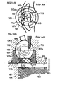
- the known combustion chamber shown in Figure 10A and Figure 10B is provided with a cylinder 101 having a cylinder head 105, a reciprocating piston 102, and a combustion chamber 109.
- the cylinder head 105 is provided with a recess 106 in which a mouthpiece 107 is fitted.
- the mouthpiece 107 is provided with a top-open recess (i.e. a bowl) 107a, and the recess 106 includes a bottom-open recess (i.e. a dome) 106a.
- the bowl 107a and the dome 106a constitute a space 108 functioning as a swirl chamber.
- the swirl chamber 108 communicates with the combustion chamber 109 through a main nozzle 111 having a centre axis 113.
- the main nozzle 111 is forwardly inclined into the swirl chamber 108.
- the mouthpiece 107 is additionally provided with a pair of sub-nozzle holes 112, through which secondary air is forced into the swirl chamber 108 on a compression stroke.
- the sub-nozzle holes 112 are symmetrically positioned on opposite sides of the central axis 113-114 as shown in Figure 10A .
- Hypothetical spheres 115 are drawn about the centre 107c of the open end 107b of the bowl 107a.
- the inner sphere has a radius which is 50% of the radius of the open end 107b and the outer sphere has a radius which is 70% of the radius of the open end 107b (corresponding to a sphere of 100% radius).
- the central axis 112a -112b of each of the sub-nozzle holes 112 passes outside the '70%' sphere 115.
- sub-nozzle holes 112, 112a deviate from the centre of the swirl chamber 108 so that the central axis 112a-112b of each sub-nozzle hole 112 does not intersect the 50% sphere 115.
- an object of the present invention is to provide an improved swirl chamber capable of causing effective swirls to help air and fuel being well mixed, and dispersing the fuel well in the swirl chamber.
- Another object of the present invention is to provide an improved swirl chamber capable of reducing the production of both NOx and fumes.
- the document JP-57-056618-A discloses a swirl chamber for use with a combustion chamber for diesel engines, wherein the combustion chamber is defined by a piston, a cylinder, and a cylinder head, comprises a mouthpiece fitted in a hole of the cylinder head, the hole having a bottom-open recess, and the mouthpiece including a top-open recess, the bottom-open recess and the top-open recess defining the swirl chamber; a main nozzle hole through a base wall of the mouthpiece to effect communication between the combustion chamber and the swirl chamber, the main nozzle hole having a forward inclination into the swirl chamber; and a pair of sub-nozzle holes positioned on opposite sides of the central axis of the main nozzle hole; wherein each of the sub-nozzle holes, which are separated from the main nozzle hole, has a central axis which intersects a hypothetical sphere concentric with the top-open recess and having a radius of 70% or less of the radius of the top-open recess.
- the invention is characterised relative to that document in that the main nozzle hole is provided with a main groove and two side grooves adjacent the main groove; and the open ends of the sub-nozzle holes are spaced away from the main nozzle hole and arranged forwards of the side grooves in the base wall of the mouthpiece.
- the document JP-2001-271646-A discloses a main nozzle hole which is provided with a main groove and two side grooves adjacent the main groove; in that document the sub-nozzle holes intersect the main groove.
- Figure 1 is generally a diagrammatic view exemplifying a first embodiment of the present invention
- Figure 1A being a plan view
- Figure 1B being a cross-sectional view taken along the line B-B of Figure 1A
- Figure 1C being a bottom view
- Figure 1D being a cross-sectional view taken along the line D-D of Figure 1B .
- Figure 2 is generally a diagrammatic view exemplifying the nozzle hole is the mouthpiece shown in Figure I, Figure 2A being a vertical cross-sectional side view of the mouthpiece, Figure 2B being a perspective view of the nozzle hole, Figure 2C being a diagrammatic view of the nozzle hole viewed in the direction indicated by the arrow C in Figure 2A, and Figure 2D being a bottom view of the nozzle hole.
- Figure 3 is generally a diagrammatic view exemplifying the swirl chamber shown in Figure 1 ;
- Figure 3A being a horizontal cross-sectional plan view of a cylinder incorporating a piston;
- Figure 3B being a cross-sectional side view of the swirl chamber and the surrounding part members.
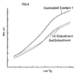
- Figure 4 is a graph showing NOx content in the exhaust gases under the first embodiment shown in Figure 3 , in comparison with a contrasted example 1 having no sub-nozzle holes.
- Figure 5 is a graph showing the amount of NOx and fumes exhausted under the first embodiment shown in Figure 3 , in comparison with contrasted examples 1 and 2.
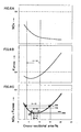
- Figure 6 is generally a graph showing the relationship between the cross-sectional area of the sub-nozzle holes and the characteristics of gases exhausted from the swirl chamber of Figure 3 , Figure 6A showing variations in the amount of NOx in relation to the cross-sectional area, and Figure 6C showing variations in the total amount of NOx and fumes in relation to the cross-sectional area.
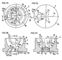
- Figure 7 is generally a diagrammatic view exemplifying the mouthpiece of a second embodiment;
- Figure 7A being a plan view
- Figure 7B being a cross-sectional view taken along the line B-B in Figure 7A
- Figure 7C being a bottom view
- Figure 7D being a cross-sectional view taken along the line D-D in Figure 7B .
- Figure 8 is generally a diagrammatic view exemplifying the mouthpiece of a third embodiment, Figure 8A being a plan view, Figure 8B being a cross-sectional view taken along the line B-B in Figure 8A, Figure 8C being a bottom view, and Figure 8D being a cross-sectional view taken along the line D-D in Figure 8B .
- Figure 9 is generally a diagrammatic view exemplifying the mouthpiece of a fourth embodiment;
- Figure 9A being a plan view
- Figure 9B being a cross-sectional view taken along the line B-B in Figure 9A
- Figure 9C being a bottom view
- Figure 9D being a cross-sectional view taken along the line D-D in Figure 9B :
- Figure 10 is generally a diagrammatic view exemplifying a known swirl chamber, Figure 10A being a plan view of the mouthpiece and the piston, and Figure 10B being a vertical cross-sectional side view of a swirl chamber and surrounding part members.
- FIGs 1B , 3B , 7B , 8B and 2A the right-hand side is 'forward', this being in the same sense as the forward direction of the main nozzle hole.
- a first embodiment is shown in Figures 1 to 6 , in which a pair of sub-nozzle holes 12 are provided upright in parallel with the central axis 3 of a cylinder 1.
- the second embodiment shown in Figure 7 is similar, but in the third embodiment shown in Figure 8 and a fourth embodiment shown in Figure 9 the sub-nozzle holes 12 slightly converge and slightly diverge toward their top open ends, respectively.
- the feature common to all the embodiments is that the sub-nozzle holes are spaced from, and positioned symmetrically on opposite sides of, the main nozzle. In addition, the sub-nozzle holes are disposed on the 'forward' side.
- a reciprocating piston 2 is provided inside a cylinder 1 along whose central axis 3 the piston 2 moves up and down.
- the cylinder 1 has a head 5 having a recess 6 in which a mouthpiece 7 is fitted.
- the recess 6 includes a bottom-open recess 6a, and the mouthpiece 7 includes a top-open recess 7a.
- the bottom-open recess 6a and the top-open recess 7a constitute a space 8 that is utilized as a swirl chamber.
- the cylinder 1 is provided with a combustion chamber 9 having a main nozzle hole 11 passing through the mouthpiece 7.
- the combustion chamber 9 and the swirl chamber 8 communicate with each other through the main nozzle hole 11, which is forwardly inclined toward the swirl chamber 8 from the combustion chamber 9, as shown in Figure 3B .
- the mouthpiece 7 has an undersurface 7d in a plane at right angles to the central axis 3 of the cylinder 1.
- a fuel jet nozzle 19 and a heat plug 20 protrude into the swirl chamber 8.
- the piston 2 is provided with a triangular recess 21 adapted to guide a gas flow.
- the root portion of the recess 21 is adapted to guide a gas flow, and is positioned immediately below the main nozzle hole 11.
- the recess 21 widens and diminishes in depth progressively away from the main nozzle hole 11.
- the sub-nozzle holes 12 are provided in pairs through a base wall 10 of the mouthpiece 7.
- Each of the sub-nozzle holes 12 is spaced from the main nozzle hole 11 such that they are symmetrically positioned about the central axis 13 of the main nozzle hole 11 or about its extension 14, depending upon the shape of the main nozzle hole 11.
- Figures 1A, 1B, and 1D show a hypothetical sphere 15 about a centre 7c which is the centre of the open end 7b of the top-open recess 7a.
- the radius of the open end 7b is supposed to be 100%, and that of the sphere 15 to be 50%.
- Each of the sub-nozzle holes 12 is positioned such that its central axis 12a-12b intersects the sphere 15.
- the radius of the sphere 15 which is thereby intersected may be 70%, but is more preferably 60%, and most preferably 50% of the radius of the open end 7b.
- the innermost, middle, and outermost spheres 15 correspond to 50%, 60% and 70% respectively of the radius of the open end 7b. It has been demonstrated that this range of angular positioning of the sub-nozzle holes 12 enables secondary air to gather at the centre of the swirl chamber 8, thereby making the most of the air ejected through the sub-nozzle holes 12 and causing effective swirls in the swirl chamber 8.
- Figure 1A shows, as a preferred embodiment, that the centre 12c of the upper open end of each sub-nozzle hole 12 overlap, as seen from above, the circle 15 having a radius of 50%, whereby the central axis 12a-12b of each sub-nozzle hole 12 passes through the middle of the swirl chamber 8.
- FIGS 1B and 1D are shown hypothetical reference lines 16 each of which, as may be seen, is parallel to the central axis 3 of the cylinder 1.
- Each sub-nozzle hole 12 is positioned such that its central axis 12a-12b exactly coincides with a respective one of the reference lines 16.
- the sub-nozzle holes 12 are positioned at various angles relative to the respective reference line 16 ( Figures 1B and 1D ). If a sub-nozzle hole is positioned at a relatively small angle to the respective reference line 16, the sub-nozzle hole 12 can be short in length, thereby reducing frictional resistance to the flow of secondary air passing through the sub-nozzle hole.
- Figure 1B wherein the cross-section of the mouthpiece 7 is viewed from the side, and the two sub-nozzle holes 12 appear to be in alignment, the central axis 12a-12b of each sub-nozzle hole 12 is inclined at a first angle to the reference line 16.
- each central axis 12a-12b is inclined at a second angle to the reference line 16.
- the first angle may be 30° or less and the second angle may be 15° or less.
- the first angle may be 15° or less and the second angle may be 8° or less.
- the first angle may be 8°and the second angle may be 4° or less.
- the first angle may be 4° or less and the second angle may be 2° or less.
- each sub-nozzle hole 12 is determined as follows:
- the total area of the open ends of the two sub-nozzle holes should be in the range of 3% to 15%; preferably 4 to 10%; more preferably 6 to 10%, and most preferably 7 to 9%. In short, the range of 3 to 15%, or preferably the range of 5 to 15% is effective to reduce the production of NOx and fumes evenly.
- the main nozzle hole 11 includes a main groove 17 and a pair of side grooves 18 communicatively continuous to the main groove 17 through banks (not numbered).
- each side groove 18 is formed such that its central axis 18a is slightly behind the central axis 17a of the main groove 17.
- Each side groove 18 is also arranged that its angle of elevation is smaller than 45° of the axis 17a.
- each of the side grooves 18 gradually but slightly narrows toward the swirl chamber while the main groove 17 remains the same in width along its full length.
- the major advantage of the first embodiment is that environmental contaminants such as NOx and fumes are reduced in the exhaust gases, which will be demonstrated, on condition that the applied load is the same.
- the first embodiment has less nitrogen oxides (NOx) than a contrasted example (1) that has neither sub-nozzle holes 12 nor the side grooves 18. It will be appreciated that the sub-nozzle holes 12 and the side grooves 18 are effective to reduce NOx content.
- NOx nitrogen oxides
- Figure 5 shows that the first embodiment has less NOx and less fumes than contrasted examples 1 and 2, wherein the contrasted example 2 has sub-nozzle holes corresponding to the sub-nozzle holes 12 but no grooves corresponding to the side grooves 18.
- the comparison between the contrasted examples 1 and 2 shows that the addition of the secondary air sub-nozzle holes 12 is conducive to the reduction of NOx and fumes.
- the comparison between the first embodiment and the contrasted example 2 shows that the side grooves 18 are conducive to the reduction of NOx and fumes.
- each horizontal co-ordinate represents the total minimum area of the open ends of the sub-nozzle holes 12 as a percentage fraction of the area of the open end of the main nozzle hole 11.
- the vertical co-ordinate of Figure 6A indicates variations in the amount of NOx; in Figure 6B the vertical co-ordinate indicates variations in the amount of fumes, and in Figure 6C the vertical co-ordinate indicates variations in the amount of NOx and fumes.
- Each coefficient of variation is calculated, as a reference value, based upon the amount of NOx and fumes produced in the combustion chamber having no sub-nozzle holes 12. Let the reference value be ⁇ , and the amount of variation be ⁇ Then, the coefficient of variation will be ( ⁇ - ⁇ )/ ⁇ .
- the reduction rate is maximised when the area of the open end of the sub-nozzle holes 12 is 7.7%. Let the value of the reduction rate at this stage be regarded as 100%. It has been demonstrated that to increase the rate of reduction of exhaust gases up to 98%, the total area of the open ends of the sub-nozzle hole 12 must be in the range of 7 to 9%, and if it is in the range of 95% to 98%, the total area can be in the range of 6 to 10%. If it is in the range of 60% to 95%, the total area can be in the range of 3 to 15%. When the reduction rate exceeds 70% of the maximum, and both NOx and fumes decrease as shown in Figures 6A and 6B the total area is in the range of 4 to 10%.
- the total area of the open ends of the sub-nozzle holes is preferably in the range of 3 to 15%, more preferably, 4 to 10%, further preferably, 6 to 10% and most preferably, 7 to 9% of the area of the open end of the main nozzle hole 11.
- the total area of the open ends of the sub-nozzle holes 12 is 8% of the area (100%) of the open end of the main nozzle hole 11, wherein each sub-nozzle hole has an open end having the same area.
- This embodiment reduces the production of NOx or fumes or both, as clearly demonstrated by comparison with the contrasted examples 1 and 2.
- the pair of sub-nozzle holes 12 are inclined so that they slightly converge in the direction toward the swirl chamber 8 from the combustion chamber 9, in contrast to the first and second embodiments wherein they extend upright between the combustion chamber 9 and the swirl chamber 8.
- the angle of convergence is 30° and in Figure 8D , the angle of convergence is 15°.
- the pair of sub-nozzle holes 12 are inclined so that they slightly diverge in the direction toward the swirl chamber 8 from the combustion chamber 9.
- the angle of divergence is 30° and in Figure 9D , the angle of divergence is 15°.
Landscapes
- Engineering & Computer Science (AREA)
- Chemical & Material Sciences (AREA)
- Combustion & Propulsion (AREA)
- Mechanical Engineering (AREA)
- General Engineering & Computer Science (AREA)
- Combustion Methods Of Internal-Combustion Engines (AREA)
Description
- The present invention relates generally to a combustion chamber for diesel engines, and more particularly, an improved swirl chamber used in association with a combustion chamber for diesel engines.
- In general, diesel engines are notorious as a major source of environmental contaminants such as NOx and fumes. However, no effective measures have been accomplished for solving those problems. It is known that these problems are due to the incomplete combustion in the engine occurring because of inadequate mixing of air and fuel. To solve these problems, swirl-aided combustion systems are commonly used. One example is disclosed in
JP-A-07-97924 Figures 10A and 10B . - In
Figures 10A and 10B the right-hand side (toward the central axis 103) is called 'rearward', and the left-hand side (toward the cylinder liner 104) is 'forward'. The known combustion chamber shown inFigure 10A and Figure 10B is provided with acylinder 101 having acylinder head 105, a reciprocatingpiston 102, and acombustion chamber 109. In addition, thecylinder head 105 is provided with arecess 106 in which amouthpiece 107 is fitted. Themouthpiece 107 is provided with a top-open recess (i.e. a bowl) 107a, and therecess 106 includes a bottom-open recess (i.e. a dome) 106a. The bowl 107a and the dome 106a constitute aspace 108 functioning as a swirl chamber. Theswirl chamber 108 communicates with thecombustion chamber 109 through amain nozzle 111 having acentre axis 113. Themain nozzle 111 is forwardly inclined into theswirl chamber 108. Themouthpiece 107 is additionally provided with a pair ofsub-nozzle holes 112, through which secondary air is forced into theswirl chamber 108 on a compression stroke. Thesub-nozzle holes 112 are symmetrically positioned on opposite sides of the central axis 113-114 as shown inFigure 10A . - Under the construction mentioned above, however, a major disadvantage is that the secondary air ejected through the
sub-nozzle holes 112 does not reach the central part of theswirl chamber 108, thereby failing to bring about effective swirls therein. In this way theconventional sub-nozzle holes 112 are not conducive to the full utilization of the secondary air. - The disadvantage mentioned above is due to the following arrangement of the sub-nozzle holes 112:
Hypothetical spheres 115 are drawn about thecentre 107c of theopen end 107b of the bowl 107a. The inner sphere has a radius which is 50% of the radius of theopen end 107b and the outer sphere has a radius which is 70% of the radius of theopen end 107b (corresponding to a sphere of 100% radius). In this situation, thecentral axis 112a -112b of each of thesub-nozzle holes 112 passes outside the '70%'sphere 115. - Furthermore, the
sub-nozzle holes swirl chamber 108 so that thecentral axis 112a-112b of eachsub-nozzle hole 112 does not intersect the 50%sphere 115. - Accordingly, an object of the present invention is to provide an improved swirl chamber capable of causing effective swirls to help air and fuel being well mixed, and dispersing the fuel well in the swirl chamber.
- Another object of the present invention is to provide an improved swirl chamber capable of reducing the production of both NOx and fumes.
- The document
JP-57-056618-A - The invention is characterised relative to that document in that the main nozzle hole is provided with a main groove and two side grooves adjacent the main groove; and the open ends of the sub-nozzle holes are spaced away from the main nozzle hole and arranged forwards of the side grooves in the base wall of the mouthpiece.
- The document
JP-2001-271646-A -
Figure 1 is generally a diagrammatic view exemplifying a first embodiment of the present invention;Figure 1A being a plan view,Figure 1B being a cross-sectional view taken along the line B-B ofFigure 1A, Figure 1C being a bottom view, andFigure 1D being a cross-sectional view taken along the line D-D ofFigure 1B . -
Figure 2 is generally a diagrammatic view exemplifying the nozzle hole is the mouthpiece shown in Figure I,Figure 2A being a vertical cross-sectional side view of the mouthpiece,Figure 2B being a perspective view of the nozzle hole,Figure 2C being a diagrammatic view of the nozzle hole viewed in the direction indicated by the arrow C inFigure 2A, and Figure 2D being a bottom view of the nozzle hole. -
Figure 3 is generally a diagrammatic view exemplifying the swirl chamber shown inFigure 1 ;Figure 3A being a horizontal cross-sectional plan view of a cylinder incorporating a piston; andFigure 3B being a cross-sectional side view of the swirl chamber and the surrounding part members. -
Figure 4 is a graph showing NOx content in the exhaust gases under the first embodiment shown inFigure 3 , in comparison with a contrasted example 1 having no sub-nozzle holes. -
Figure 5 is a graph showing the amount of NOx and fumes exhausted under the first embodiment shown inFigure 3 , in comparison with contrasted examples 1 and 2. -
Figure 6 is generally a graph showing the relationship between the cross-sectional area of the sub-nozzle holes and the characteristics of gases exhausted from the swirl chamber ofFigure 3 ,Figure 6A showing variations in the amount of NOx in relation to the cross-sectional area, andFigure 6C showing variations in the total amount of NOx and fumes in relation to the cross-sectional area. -
Figure 7 is generally a diagrammatic view exemplifying the mouthpiece of a second embodiment;Figure 7A being a plan view,Figure 7B being a cross-sectional view taken along the line B-B inFigure 7A, Figure 7C being a bottom view, andFigure 7D being a cross-sectional view taken along the line D-D inFigure 7B . -
Figure 8 is generally a diagrammatic view exemplifying the mouthpiece of a third embodiment,Figure 8A being a plan view,Figure 8B being a cross-sectional view taken along the line B-B inFigure 8A, Figure 8C being a bottom view, andFigure 8D being a cross-sectional view taken along the line D-D inFigure 8B . -
Figure 9 is generally a diagrammatic view exemplifying the mouthpiece of a fourth embodiment;Figure 9A being a plan view,Figure 9B being a cross-sectional view taken along the line B-B inFigure 9A, Figure 9C being a bottom view, andFigure 9D being a cross-sectional view taken along the line D-D inFigure 9B : and -
Figure 10 is generally a diagrammatic view exemplifying a known swirl chamber,Figure 10A being a plan view of the mouthpiece and the piston, andFigure 10B being a vertical cross-sectional side view of a swirl chamber and surrounding part members. - In
Figures 1B ,3B ,7B ,8B and2A the right-hand side is 'forward', this being in the same sense as the forward direction of the main nozzle hole. A first embodiment is shown inFigures 1 to 6 , in which a pair ofsub-nozzle holes 12 are provided upright in parallel with thecentral axis 3 of acylinder 1. The second embodiment shown inFigure 7 is similar, but in the third embodiment shown inFigure 8 and a fourth embodiment shown inFigure 9 thesub-nozzle holes 12 slightly converge and slightly diverge toward their top open ends, respectively. The feature common to all the embodiments is that the sub-nozzle holes are spaced from, and positioned symmetrically on opposite sides of, the main nozzle. In addition, the sub-nozzle holes are disposed on the 'forward' side. - In
Figure 3B a reciprocatingpiston 2 is provided inside acylinder 1 along whosecentral axis 3 thepiston 2 moves up and down. Thecylinder 1 has ahead 5 having arecess 6 in which amouthpiece 7 is fitted. Therecess 6 includes a bottom-open recess 6a, and themouthpiece 7 includes a top-open recess 7a. The bottom-open recess 6a and the top-open recess 7a constitute aspace 8 that is utilized as a swirl chamber. Thecylinder 1 is provided with acombustion chamber 9 having amain nozzle hole 11 passing through themouthpiece 7. Thecombustion chamber 9 and theswirl chamber 8 communicate with each other through themain nozzle hole 11, which is forwardly inclined toward theswirl chamber 8 from thecombustion chamber 9, as shown inFigure 3B . Themouthpiece 7 has anundersurface 7d in a plane at right angles to thecentral axis 3 of thecylinder 1. - As best shown in
Figure 3B , afuel jet nozzle 19 and aheat plug 20 protrude into theswirl chamber 8. Thepiston 2 is provided with atriangular recess 21 adapted to guide a gas flow. The root portion of therecess 21 is adapted to guide a gas flow, and is positioned immediately below themain nozzle hole 11. The recess 21 widens and diminishes in depth progressively away from themain nozzle hole 11. - The principle underlying the
combustion chamber 9 fixed with theswirl chamber 8 is as follows: - On the compression stroke the
piston 2 rises, thereby introducing compressed air into theswirl chamber 8 to cause swirls therein. When thepiston 2 reaches the top dead point, fuel is ejected through theejection nozzle 19. The fuel is mixed with the air in theswirl chamber 8, and as a result, it expands in volume. The expanded gases pass into thecombustion chamber 9 through themain nozzle hole 1. The fresh charge expands and rises as it goes away from themain nozzle hole 11 in thetriangular recess 21. The fuel-content in the fresh charge mixes with the air in thecombustion chamber 9, and the mixture is ignited and burned. - As shown in
Figures 1A to 1D , and particularly inFigures 1B and 1D , thesub-nozzle holes 12 are provided in pairs through abase wall 10 of themouthpiece 7. Each of thesub-nozzle holes 12 is spaced from themain nozzle hole 11 such that they are symmetrically positioned about thecentral axis 13 of themain nozzle hole 11 or about itsextension 14, depending upon the shape of themain nozzle hole 11. -
Figures 1A, 1B, and 1D show ahypothetical sphere 15 about acentre 7c which is the centre of theopen end 7b of the top-open recess 7a. The radius of theopen end 7b is supposed to be 100%, and that of thesphere 15 to be 50%. Each of the sub-nozzle holes 12 is positioned such that itscentral axis 12a-12b intersects thesphere 15. - The radius of the
sphere 15 which is thereby intersected may be 70%, but is more preferably 60%, and most preferably 50% of the radius of theopen end 7b. InFigures 1A, 1B, and 1D the innermost, middle, andoutermost spheres 15 correspond to 50%, 60% and 70% respectively of the radius of theopen end 7b. It has been demonstrated that this range of angular positioning of the sub-nozzle holes 12 enables secondary air to gather at the centre of theswirl chamber 8, thereby making the most of the air ejected through thesub-nozzle holes 12 and causing effective swirls in theswirl chamber 8. -
Figure 1A shows, as a preferred embodiment, that thecentre 12c of the upper open end of eachsub-nozzle hole 12 overlap, as seen from above, thecircle 15 having a radius of 50%, whereby thecentral axis 12a-12b of eachsub-nozzle hole 12 passes through the middle of theswirl chamber 8. - In
Figures 1B and 1D are shownhypothetical reference lines 16 each of which, as may be seen, is parallel to thecentral axis 3 of thecylinder 1. Eachsub-nozzle hole 12 is positioned such that itscentral axis 12a-12b exactly coincides with a respective one of the reference lines 16. - In this way the
sub-nozzle holes 12 are positioned at various angles relative to the respective reference line 16 (Figures 1B and 1D ). If a sub-nozzle hole is positioned at a relatively small angle to therespective reference line 16, thesub-nozzle hole 12 can be short in length, thereby reducing frictional resistance to the flow of secondary air passing through the sub-nozzle hole. InFigure 1B , wherein the cross-section of themouthpiece 7 is viewed from the side, and the twosub-nozzle holes 12 appear to be in alignment, thecentral axis 12a-12b of eachsub-nozzle hole 12 is inclined at a first angle to thereference line 16. InFigure 1D , wherein the cross-section of themouthpiece 7 is viewed from the back, and the sub-nozzle holes appear to be arranged side by side, eachcentral axis 12a-12b is inclined at a second angle to thereference line 16. The first angle may be 30° or less and the second angle may be 15° or less. The first angle may be 15° or less and the second angle may be 8° or less. The first angle may be 8°and the second angle may be 4° or less. The first angle may be 4° or less and the second angle may be 2° or less. - In the embodiment illustrated in
Figures 1B and 1C the first angle is 30° and the second angle is 15°, each angular relation is indicated by chain lines.
The size of eachsub-nozzle hole 12 is determined as follows: - It has been demonstrated that if the
main nozzle hole 11 has an open end of which the effective area is supposed to be 100%, the total area of the open ends of the two sub-nozzle holes should be in the range of 3% to 15%; preferably 4 to 10%; more preferably 6 to 10%, and most preferably 7 to 9%. In short, the range of 3 to 15%, or preferably the range of 5 to 15% is effective to reduce the production of NOx and fumes evenly. - Referring to
Figures 2A to 2D , themain nozzle hole 11 includes amain groove 17 and a pair ofside grooves 18 communicatively continuous to themain groove 17 through banks (not numbered). InFigure 2A , eachside groove 18 is formed such that itscentral axis 18a is slightly behind thecentral axis 17a of themain groove 17. Eachside groove 18 is also arranged that its angle of elevation is smaller than 45° of theaxis 17a. - As best shown in
Figure 1A , each of theside grooves 18 gradually but slightly narrows toward the swirl chamber while themain groove 17 remains the same in width along its full length. - Referring to
Figures 4 and5 , the major advantage of the first embodiment is that environmental contaminants such as NOx and fumes are reduced in the exhaust gases, which will be demonstrated, on condition that the applied load is the same. - From
Figure 4 , it will be understood that the first embodiment has less nitrogen oxides (NOx) than a contrasted example (1) that has neithersub-nozzle holes 12 nor theside grooves 18. It will be appreciated that thesub-nozzle holes 12 and theside grooves 18 are effective to reduce NOx content. -
Figure 5 shows that the first embodiment has less NOx and less fumes than contrasted examples 1 and 2, wherein the contrasted example 2 has sub-nozzle holes corresponding to thesub-nozzle holes 12 but no grooves corresponding to theside grooves 18. The comparison between the contrasted examples 1 and 2 shows that the addition of the secondary air sub-nozzle holes 12 is conducive to the reduction of NOx and fumes. Likewise, the comparison between the first embodiment and the contrasted example 2 shows that theside grooves 18 are conducive to the reduction of NOx and fumes. - The efficacy with which exhaust gases are reduced depends upon the area of the open end of the sub-nozzle holes 12. Referring to
Figure 6A to 6C , each horizontal co-ordinate represents the total minimum area of the open ends of thesub-nozzle holes 12 as a percentage fraction of the area of the open end of themain nozzle hole 11. The vertical co-ordinate ofFigure 6A indicates variations in the amount of NOx; inFigure 6B the vertical co-ordinate indicates variations in the amount of fumes, and inFigure 6C the vertical co-ordinate indicates variations in the amount of NOx and fumes. Each coefficient of variation is calculated, as a reference value, based upon the amount of NOx and fumes produced in the combustion chamber having no sub-nozzle holes 12. Let the reference value be α, and the amount of variation be β Then, the coefficient of variation will be (β-α)/α. - As shown in
Figure 6C , the reduction rate is maximised when the area of the open end of the sub-nozzle holes 12 is 7.7%. Let the value of the reduction rate at this stage be regarded as 100%. It has been demonstrated that to increase the rate of reduction of exhaust gases up to 98%, the total area of the open ends of thesub-nozzle hole 12 must be in the range of 7 to 9%, and if it is in the range of 95% to 98%, the total area can be in the range of 6 to 10%. If it is in the range of 60% to 95%, the total area can be in the range of 3 to 15%. When the reduction rate exceeds 70% of the maximum, and both NOx and fumes decrease as shown inFigures 6A and 6B the total area is in the range of 4 to 10%. As a result, it will be concluded that the total area of the open ends of the sub-nozzle holes is preferably in the range of 3 to 15%, more preferably, 4 to 10%, further preferably, 6 to 10% and most preferably, 7 to 9% of the area of the open end of themain nozzle hole 11. - Referring to
Figures 7 ,8 and9 , a second embodiment, a third embodiment and a fourth embodiment will be described, respectively. - In the second embodiment, shown in
Figure 7 the total area of the open ends of the sub-nozzle holes 12 is 8% of the area (100%) of the open end of themain nozzle hole 11, wherein each sub-nozzle hole has an open end having the same area. This embodiment reduces the production of NOx or fumes or both, as clearly demonstrated by comparison with the contrasted examples 1 and 2. - In the third embodiment shown in
Figure 8 the pair ofsub-nozzle holes 12 are inclined so that they slightly converge in the direction toward theswirl chamber 8 from thecombustion chamber 9, in contrast to the first and second embodiments wherein they extend upright between thecombustion chamber 9 and theswirl chamber 8. InFigure 8B the angle of convergence is 30° and inFigure 8D , the angle of convergence is 15°. - In the fourth embodiment shown in
Figure 9A to 9D , the pair ofsub-nozzle holes 12 are inclined so that they slightly diverge in the direction toward theswirl chamber 8 from thecombustion chamber 9. InFigure 9B the angle of divergence is 30° and inFigure 9D , the angle of divergence is 15°.
Claims (13)
- A swirl chamber (8) for use with a combustion chamber (9) for diesel engines, wherein the combustion chamber (9) is defined by a piston (2), a cylinder (1), and a cylinder head (5), the swirl chamber (8) comprising:a mouthpiece (7) fitted in a hole (6) of the cylinder head (5), the hole having a bottom-open recess (6a), and the mouthpiece (7) including a top-open recess (7a) having an open end (7b), the bottom-open recess (6a) and the top-open recess (7a) defining the swirl chamber (8);a main nozzle hole (11) through a base wall (10) of the mouthpiece to effect communication between the combustion chamber (9) and the swirl chamber (8), the main nozzle hole (11) having a forward inclination, i.e. an inclination from the combustion chamber (9) towards the cylinder head (5) and radially outwards with respect to the cylinder's central axis (3), into the swirl chamber (8); anda pair of sub-nozzle holes (12) positioned on opposite sides of the central axis (13) of the main nozzle hole (11);wherein each of the sub-nozzle holes (12), which are separated from the main nozzle hole (11), has a central axis (12a, 12b) which intersects hypothetical sphere (15) concentric with the centre (7c) of the open end (7b) of the top-open recess (7a) and having a radius of 70% or less of the radius of the open end (7b) of the top-open recess;
characterised in that the main nozzle hole (11) is provided with a main groove (17) and two side grooves (18) adjacent and communicatively continuous to the main groove (17); and the open ends of the sub-nozzle holes (12) are spaced away from the main nozzle hole (11) and positioned forwards, i.e. radially outwards with respect to the cylinder's central axis (3), of the side grooves (18) in the base wall of the mouthpiece (7). - A swirl chamber according to claim 1, wherein the radius of the sphere is 60% or less of the radius of the top-open recess (7a)
- A swirl chamber according to claim 2, wherein the sphere (15) has a radius of 50% of the radius of the top-open recess (7a).
- A swirl chamber according to any of claims 1 - 3 wherein each of the sub-nozzle holes is positioned such that its central axis (12a, 12b) is inclined at an angle between 0° and 30° away from a reference line (16) parallel to the central axis (3) of the cylinder (1).
- A swirl chamber according to claim 4 wherein the angle is 0° to 15°.
- A swirl chamber according to any of claims 1 - 3 wherein the sub-nozzle holes (12) are positioned such that their central axes (12a, 12b) are upright on the base wall of the mouthpiece.
- A swirl chamber according to any of claims 1 - 3 wherein the sub-nozzle holes (12) are positioned such that the distance between them becomes narrower toward their top open ends.
- A swirl chamber according to any of claims 1 - 3 wherein the sub-nozzle holes (12) are positioned such that the distance between them becomes wider toward their top open ends.
- A swirl chamber according to any foregoing claim, wherein the total area of the open ends of the sub-nozzle holes (12) is in the range between 3% and 15% of that of the main nozzle hole (11).
- A swirl chamber according to claim 9 wherein the said total area is between 4% and 10% of that of the main nozzle hole (11).
- A swirl chamber according to any foregoing claim wherein the side grooves (18) are positioned such that their central axes are slightly behind that of the main groove (17), i.e. slightly nearer the cylinder's central axis (3).
- A swirl chamber according to any foregoing wherein each of the side grooves (18) has its central axis inclined at a smaller angle than the angle at which the central axis of the main groove (17) is inclined with respect to the level of a base wall of the mouthpiece (7).
- A swirl chamber according to any foregoing claim, wherein each of the side grooves (18) narrows toward its forward end.
Applications Claiming Priority (6)
| Application Number | Priority Date | Filing Date | Title |
|---|---|---|---|
| JP2002282390 | 2002-09-27 | ||
| JP2002282390 | 2002-09-27 | ||
| JP2003082996A JP4088545B2 (en) | 2002-09-27 | 2003-03-25 | Diesel engine vortex chamber combustion chamber communication passage |
| JP2003082996 | 2003-03-25 | ||
| JP2003283365A JP4085035B2 (en) | 2003-07-31 | 2003-07-31 | Diesel engine vortex chamber combustion chamber |
| JP2003283365 | 2003-07-31 |
Publications (3)
| Publication Number | Publication Date |
|---|---|
| EP1403482A2 EP1403482A2 (en) | 2004-03-31 |
| EP1403482A3 EP1403482A3 (en) | 2007-02-14 |
| EP1403482B1 true EP1403482B1 (en) | 2010-04-21 |
Family
ID=31982153
Family Applications (1)
| Application Number | Title | Priority Date | Filing Date |
|---|---|---|---|
| EP03019967A Expired - Lifetime EP1403482B1 (en) | 2002-09-27 | 2003-09-03 | Swirl chamber used in association with a combustion chamber for diesel engines |
Country Status (4)
| Country | Link |
|---|---|
| US (2) | US6899076B2 (en) |
| EP (1) | EP1403482B1 (en) |
| CN (1) | CN100356044C (en) |
| DE (1) | DE60332203D1 (en) |
Families Citing this family (37)
| Publication number | Priority date | Publication date | Assignee | Title |
|---|---|---|---|---|
| US8635985B2 (en) | 2008-01-07 | 2014-01-28 | Mcalister Technologies, Llc | Integrated fuel injectors and igniters and associated methods of use and manufacture |
| US8413634B2 (en) | 2008-01-07 | 2013-04-09 | Mcalister Technologies, Llc | Integrated fuel injector igniters with conductive cable assemblies |
| US8074625B2 (en) | 2008-01-07 | 2011-12-13 | Mcalister Technologies, Llc | Fuel injector actuator assemblies and associated methods of use and manufacture |
| US8365700B2 (en) | 2008-01-07 | 2013-02-05 | Mcalister Technologies, Llc | Shaping a fuel charge in a combustion chamber with multiple drivers and/or ionization control |
| US8225768B2 (en) | 2008-01-07 | 2012-07-24 | Mcalister Technologies, Llc | Integrated fuel injector igniters suitable for large engine applications and associated methods of use and manufacture |
| US8561598B2 (en) | 2008-01-07 | 2013-10-22 | Mcalister Technologies, Llc | Method and system of thermochemical regeneration to provide oxygenated fuel, for example, with fuel-cooled fuel injectors |
| US8387599B2 (en) | 2008-01-07 | 2013-03-05 | Mcalister Technologies, Llc | Methods and systems for reducing the formation of oxides of nitrogen during combustion in engines |
| US7628137B1 (en) | 2008-01-07 | 2009-12-08 | Mcalister Roy E | Multifuel storage, metering and ignition system |
| JP5563660B2 (en) | 2009-08-27 | 2014-07-30 | マクアリスター テクノロジーズ エルエルシー | Ceramic insulator and use and manufacturing method thereof |
| CA2772044C (en) | 2009-08-27 | 2013-04-16 | Mcalister Technologies, Llc | Shaping a fuel charge in a combustion chamber with multiple drivers and/or ionization control |
| KR101364416B1 (en) | 2009-12-07 | 2014-02-17 | 맥알리스터 테크놀로지즈 엘엘씨 | Integrated fuel injector igniters suitable for large engine applications and associated methods of use and manufacture |
| KR20120086375A (en) | 2009-12-07 | 2012-08-02 | 맥알리스터 테크놀로지즈 엘엘씨 | Adaptive control system for fuel injectors and igniters |
| EP2534347B1 (en) | 2010-02-13 | 2016-05-04 | McAlister, Roy Edward | Methods and systems for adaptively cooling combustion chambers in engines |
| WO2011100701A2 (en) | 2010-02-13 | 2011-08-18 | Mcalister Roy E | Fuel injector assemblies having acoustical force modifiers and associated methods of use and manufacture |
| US20110297753A1 (en) | 2010-12-06 | 2011-12-08 | Mcalister Roy E | Integrated fuel injector igniters configured to inject multiple fuels and/or coolants and associated methods of use and manufacture |
| US8528519B2 (en) | 2010-10-27 | 2013-09-10 | Mcalister Technologies, Llc | Integrated fuel injector igniters suitable for large engine applications and associated methods of use and manufacture |
| US8091528B2 (en) | 2010-12-06 | 2012-01-10 | Mcalister Technologies, Llc | Integrated fuel injector igniters having force generating assemblies for injecting and igniting fuel and associated methods of use and manufacture |
| AT510869B1 (en) * | 2010-12-27 | 2013-04-15 | Ge Jenbacher Gmbh & Co Ohg | Internal combustion engine |
| US8820275B2 (en) | 2011-02-14 | 2014-09-02 | Mcalister Technologies, Llc | Torque multiplier engines |
| CN103890343B (en) | 2011-08-12 | 2015-07-15 | 麦卡利斯特技术有限责任公司 | Systems and methods for improved engine cooling and power generation |
| US8919377B2 (en) | 2011-08-12 | 2014-12-30 | Mcalister Technologies, Llc | Acoustically actuated flow valve assembly including a plurality of reed valves |
| US8851047B2 (en) | 2012-08-13 | 2014-10-07 | Mcallister Technologies, Llc | Injector-igniters with variable gap electrode |
| US8746197B2 (en) | 2012-11-02 | 2014-06-10 | Mcalister Technologies, Llc | Fuel injection systems with enhanced corona burst |
| US9169814B2 (en) | 2012-11-02 | 2015-10-27 | Mcalister Technologies, Llc | Systems, methods, and devices with enhanced lorentz thrust |
| US9169821B2 (en) | 2012-11-02 | 2015-10-27 | Mcalister Technologies, Llc | Fuel injection systems with enhanced corona burst |
| US9309846B2 (en) | 2012-11-12 | 2016-04-12 | Mcalister Technologies, Llc | Motion modifiers for fuel injection systems |
| US9115325B2 (en) | 2012-11-12 | 2015-08-25 | Mcalister Technologies, Llc | Systems and methods for utilizing alcohol fuels |
| US20140131466A1 (en) | 2012-11-12 | 2014-05-15 | Advanced Green Innovations, LLC | Hydraulic displacement amplifiers for fuel injectors |
| US9200561B2 (en) | 2012-11-12 | 2015-12-01 | Mcalister Technologies, Llc | Chemical fuel conditioning and activation |
| US8800527B2 (en) | 2012-11-19 | 2014-08-12 | Mcalister Technologies, Llc | Method and apparatus for providing adaptive swirl injection and ignition |
| US9194337B2 (en) | 2013-03-14 | 2015-11-24 | Advanced Green Innovations, LLC | High pressure direct injected gaseous fuel system and retrofit kit incorporating the same |
| US9562500B2 (en) | 2013-03-15 | 2017-02-07 | Mcalister Technologies, Llc | Injector-igniter with fuel characterization |
| US8820293B1 (en) | 2013-03-15 | 2014-09-02 | Mcalister Technologies, Llc | Injector-igniter with thermochemical regeneration |
| US9334794B2 (en) * | 2013-06-05 | 2016-05-10 | Pratt & Whitney Canada Corp. | Rotary internal combustion engine with pilot subchamber and ignition element |
| CN105849380B (en) | 2013-09-25 | 2019-08-02 | 艾尼森生态技术有限公司 | self-cooling engine |
| CN104653275A (en) * | 2013-11-20 | 2015-05-27 | 铜陵市大成轧辊有限责任公司 | Separated combustion device for internal combustion engine |
| JP6895243B2 (en) * | 2016-12-08 | 2021-06-30 | 三菱重工エンジン&ターボチャージャ株式会社 | Sub-chamber gas engine |
Family Cites Families (18)
| Publication number | Priority date | Publication date | Assignee | Title |
|---|---|---|---|---|
| US2380615A (en) * | 1941-11-01 | 1945-07-31 | Richard H Sheppard | Combustion chamber |
| JPS5349609A (en) * | 1976-10-19 | 1978-05-06 | Nissan Diesel Motor Co Ltd | Turbulent type combustion chamber |
| JPS5756618A (en) * | 1980-09-17 | 1982-04-05 | Daihatsu Motor Co Ltd | Swirl-chamber diesel engine |
| JPS603236U (en) | 1983-06-22 | 1985-01-11 | 三菱重工業株式会社 | Combustion chamber of pre-chamber diesel engine |
| JPS6095129A (en) | 1983-10-31 | 1985-05-28 | Yanmar Diesel Engine Co Ltd | Convolutional combustion chamber of diesel engine |
| DE3519835A1 (en) * | 1984-06-07 | 1985-12-12 | Nissan Motor Co., Ltd., Yokohama, Kanagawa | COMBUSTION ENGINE |
| JPS61171821A (en) * | 1985-01-25 | 1986-08-02 | Nissan Motor Co Ltd | Diesel engine with swirl chamber |
| JPH0643806B2 (en) * | 1986-05-23 | 1994-06-08 | 株式会社クボタ | Whirlpool combustion chamber of diesel engine |
| JPS6434657A (en) * | 1987-07-29 | 1989-02-06 | Fujitsu Ltd | Gaseous pressure type polishing device |
| JPS6491034A (en) * | 1987-10-02 | 1989-04-10 | Toshiba Corp | Corrosion apparatus for observing metal texture |
| JPH0191034U (en) | 1987-12-09 | 1989-06-15 | ||
| JP3047057B2 (en) * | 1992-05-15 | 2000-05-29 | 株式会社クボタ | Diesel engine swirl chamber |
| JP3355723B2 (en) * | 1993-09-29 | 2002-12-09 | 井関農機株式会社 | Diesel engine combustion chamber |
| JP3406119B2 (en) * | 1995-06-05 | 2003-05-12 | ヤマハ発動機株式会社 | 2-stroke diesel engine with swirl chamber auxiliary combustion chamber |
| JP3332694B2 (en) * | 1995-09-22 | 2002-10-07 | 三菱重工業株式会社 | Combustion chamber of subchamber internal combustion engine |
| JP3191003B2 (en) | 1996-09-06 | 2001-07-23 | 株式会社クボタ | Diesel engine subchamber combustion chamber |
| JPH11294168A (en) * | 1998-04-15 | 1999-10-26 | Ishikawajima Shibaura Mach Co Ltd | Sub-combustion chamber of diesel engine |
| JP2001271646A (en) * | 2000-03-24 | 2001-10-05 | Kubota Corp | Vortex chamber combustion chamber of a diesel engine |
-
2003
- 2003-09-03 DE DE60332203T patent/DE60332203D1/en not_active Expired - Lifetime
- 2003-09-03 EP EP03019967A patent/EP1403482B1/en not_active Expired - Lifetime
- 2003-09-16 US US10/663,186 patent/US6899076B2/en not_active Ceased
- 2003-09-19 CN CNB031587046A patent/CN100356044C/en not_active Expired - Lifetime
-
2006
- 2006-11-17 US US11/601,616 patent/USRE41344E1/en not_active Expired - Lifetime
Also Published As
| Publication number | Publication date |
|---|---|
| CN1492131A (en) | 2004-04-28 |
| EP1403482A3 (en) | 2007-02-14 |
| US20040060536A1 (en) | 2004-04-01 |
| CN100356044C (en) | 2007-12-19 |
| USRE41344E1 (en) | 2010-05-25 |
| EP1403482A2 (en) | 2004-03-31 |
| DE60332203D1 (en) | 2010-06-02 |
| US6899076B2 (en) | 2005-05-31 |
Similar Documents
| Publication | Publication Date | Title |
|---|---|---|
| US6899076B2 (en) | Swirl chamber used in association with a combustion chamber for diesel engines | |
| US6874489B2 (en) | Combustion chamber structure for internal combustion engine | |
| US4881501A (en) | Diesel engine having shaped flame dispersing recess in piston crown | |
| US4005684A (en) | Internal combustion engine | |
| JPS5820369B2 (en) | Combustion chamber structure of internal combustion engine | |
| JPS6236132B2 (en) | ||
| CN109751114B (en) | Combustion chamber structure of internal combustion engine | |
| JP3332694B2 (en) | Combustion chamber of subchamber internal combustion engine | |
| US5067457A (en) | Swirl chamber type diesel engine | |
| KR101034072B1 (en) | Swirl chamber used in association with a combustion chamber for diesel engines | |
| JPS5851215A (en) | Combustion chamber for vortex chamber type diesel engine | |
| EP1707778A1 (en) | Internal combustion engine | |
| CN111322170B (en) | Direct injection internal combustion engine piston combustion chamber | |
| GB1561729A (en) | Pre-combustion chamber diesel engines | |
| US11085359B2 (en) | Swirl chamber-type diesel engine | |
| JP2816925B2 (en) | Secondary combustion chamber diesel engine | |
| JP4363385B2 (en) | Piston for internal combustion engine | |
| JPS611823A (en) | Eddy-current chamber type diesel engine | |
| JP4738930B2 (en) | Piston for internal combustion engine | |
| JPS58128417A (en) | Combustion chamber structure of engine | |
| JP3013572B2 (en) | Combustion chamber of a swirl chamber type diesel engine | |
| JPH07208168A (en) | Eddy current diesel engine combustion chamber | |
| JPH02123223A (en) | Combustion chamber of internal combustion engine | |
| JP2563943B2 (en) | Engine combustion chamber structure | |
| JPS62258116A (en) | Combustion chamber structure for engine |
Legal Events
| Date | Code | Title | Description |
|---|---|---|---|
| PUAI | Public reference made under article 153(3) epc to a published international application that has entered the european phase |
Free format text: ORIGINAL CODE: 0009012 |
|
| AK | Designated contracting states |
Kind code of ref document: A2 Designated state(s): AT BE BG CH CY CZ DE DK EE ES FI FR GB GR HU IE IT LI LU MC NL PT RO SE SI SK TR |
|
| AX | Request for extension of the european patent |
Extension state: AL LT LV MK |
|
| PUAL | Search report despatched |
Free format text: ORIGINAL CODE: 0009013 |
|
| AK | Designated contracting states |
Kind code of ref document: A3 Designated state(s): AT BE BG CH CY CZ DE DK EE ES FI FR GB GR HU IE IT LI LU MC NL PT RO SE SI SK TR |
|
| AX | Request for extension of the european patent |
Extension state: AL LT LV MK |
|
| RIC1 | Information provided on ipc code assigned before grant |
Ipc: F02B 19/08 20060101ALN20070108BHEP Ipc: F02B 19/18 20060101AFI20070108BHEP Ipc: F02B 19/14 20060101ALN20070108BHEP |
|
| 17P | Request for examination filed |
Effective date: 20070806 |
|
| AKX | Designation fees paid |
Designated state(s): DE FR GB IT |
|
| 17Q | First examination report despatched |
Effective date: 20071005 |
|
| GRAP | Despatch of communication of intention to grant a patent |
Free format text: ORIGINAL CODE: EPIDOSNIGR1 |
|
| GRAS | Grant fee paid |
Free format text: ORIGINAL CODE: EPIDOSNIGR3 |
|
| GRAA | (expected) grant |
Free format text: ORIGINAL CODE: 0009210 |
|
| AK | Designated contracting states |
Kind code of ref document: B1 Designated state(s): DE FR GB IT |
|
| REG | Reference to a national code |
Ref country code: GB Ref legal event code: FG4D |
|
| REF | Corresponds to: |
Ref document number: 60332203 Country of ref document: DE Date of ref document: 20100602 Kind code of ref document: P |
|
| PLBE | No opposition filed within time limit |
Free format text: ORIGINAL CODE: 0009261 |
|
| STAA | Information on the status of an ep patent application or granted ep patent |
Free format text: STATUS: NO OPPOSITION FILED WITHIN TIME LIMIT |
|
| 26N | No opposition filed |
Effective date: 20110124 |
|
| REG | Reference to a national code |
Ref country code: FR Ref legal event code: PLFP Year of fee payment: 14 |
|
| REG | Reference to a national code |
Ref country code: FR Ref legal event code: PLFP Year of fee payment: 15 |
|
| REG | Reference to a national code |
Ref country code: FR Ref legal event code: PLFP Year of fee payment: 16 |
|
| PGFP | Annual fee paid to national office [announced via postgrant information from national office to epo] |
Ref country code: IT Payment date: 20220811 Year of fee payment: 20 Ref country code: GB Payment date: 20220728 Year of fee payment: 20 Ref country code: DE Payment date: 20220621 Year of fee payment: 20 |
|
| PGFP | Annual fee paid to national office [announced via postgrant information from national office to epo] |
Ref country code: FR Payment date: 20220808 Year of fee payment: 20 |
|
| REG | Reference to a national code |
Ref country code: DE Ref legal event code: R071 Ref document number: 60332203 Country of ref document: DE |
|
| REG | Reference to a national code |
Ref country code: GB Ref legal event code: PE20 Expiry date: 20230902 |
|
| PG25 | Lapsed in a contracting state [announced via postgrant information from national office to epo] |
Ref country code: GB Free format text: LAPSE BECAUSE OF EXPIRATION OF PROTECTION Effective date: 20230902 |