EP1403391A1 - Martensitic stainless steel - Google Patents
Martensitic stainless steel Download PDFInfo
- Publication number
- EP1403391A1 EP1403391A1 EP02728217A EP02728217A EP1403391A1 EP 1403391 A1 EP1403391 A1 EP 1403391A1 EP 02728217 A EP02728217 A EP 02728217A EP 02728217 A EP02728217 A EP 02728217A EP 1403391 A1 EP1403391 A1 EP 1403391A1
- Authority
- EP
- European Patent Office
- Prior art keywords
- content
- carbides
- steel
- mass
- type
- Prior art date
- Legal status (The legal status is an assumption and is not a legal conclusion. Google has not performed a legal analysis and makes no representation as to the accuracy of the status listed.)
- Granted
Links
Images

Classifications
-
- C—CHEMISTRY; METALLURGY
- C22—METALLURGY; FERROUS OR NON-FERROUS ALLOYS; TREATMENT OF ALLOYS OR NON-FERROUS METALS
- C22C—ALLOYS
- C22C38/00—Ferrous alloys, e.g. steel alloys
- C22C38/18—Ferrous alloys, e.g. steel alloys containing chromium
- C22C38/40—Ferrous alloys, e.g. steel alloys containing chromium with nickel
- C22C38/44—Ferrous alloys, e.g. steel alloys containing chromium with nickel with molybdenum or tungsten
-
- C—CHEMISTRY; METALLURGY
- C22—METALLURGY; FERROUS OR NON-FERROUS ALLOYS; TREATMENT OF ALLOYS OR NON-FERROUS METALS
- C22C—ALLOYS
- C22C38/00—Ferrous alloys, e.g. steel alloys
- C22C38/18—Ferrous alloys, e.g. steel alloys containing chromium
- C22C38/40—Ferrous alloys, e.g. steel alloys containing chromium with nickel
- C22C38/42—Ferrous alloys, e.g. steel alloys containing chromium with nickel with copper
-
- C—CHEMISTRY; METALLURGY
- C22—METALLURGY; FERROUS OR NON-FERROUS ALLOYS; TREATMENT OF ALLOYS OR NON-FERROUS METALS
- C22C—ALLOYS
- C22C38/00—Ferrous alloys, e.g. steel alloys
- C22C38/18—Ferrous alloys, e.g. steel alloys containing chromium
- C22C38/40—Ferrous alloys, e.g. steel alloys containing chromium with nickel
- C22C38/46—Ferrous alloys, e.g. steel alloys containing chromium with nickel with vanadium
-
- C—CHEMISTRY; METALLURGY
- C21—METALLURGY OF IRON
- C21D—MODIFYING THE PHYSICAL STRUCTURE OF FERROUS METALS; GENERAL DEVICES FOR HEAT TREATMENT OF FERROUS OR NON-FERROUS METALS OR ALLOYS; MAKING METAL MALLEABLE, e.g. BY DECARBURISATION OR TEMPERING
- C21D2211/00—Microstructure comprising significant phases
- C21D2211/008—Martensite
-
- C—CHEMISTRY; METALLURGY
- C21—METALLURGY OF IRON
- C21D—MODIFYING THE PHYSICAL STRUCTURE OF FERROUS METALS; GENERAL DEVICES FOR HEAT TREATMENT OF FERROUS OR NON-FERROUS METALS OR ALLOYS; MAKING METAL MALLEABLE, e.g. BY DECARBURISATION OR TEMPERING
- C21D8/00—Modifying the physical properties of ferrous metals or ferrous alloys by deformation combined with, or followed by, heat treatment
-
- C—CHEMISTRY; METALLURGY
- C21—METALLURGY OF IRON
- C21D—MODIFYING THE PHYSICAL STRUCTURE OF FERROUS METALS; GENERAL DEVICES FOR HEAT TREATMENT OF FERROUS OR NON-FERROUS METALS OR ALLOYS; MAKING METAL MALLEABLE, e.g. BY DECARBURISATION OR TEMPERING
- C21D8/00—Modifying the physical properties of ferrous metals or ferrous alloys by deformation combined with, or followed by, heat treatment
- C21D8/02—Modifying the physical properties of ferrous metals or ferrous alloys by deformation combined with, or followed by, heat treatment during manufacturing of plates or strips
- C21D8/0247—Modifying the physical properties of ferrous metals or ferrous alloys by deformation combined with, or followed by, heat treatment during manufacturing of plates or strips characterised by the heat treatment
- C21D8/0263—Modifying the physical properties of ferrous metals or ferrous alloys by deformation combined with, or followed by, heat treatment during manufacturing of plates or strips characterised by the heat treatment following hot rolling
Definitions
- the present invention relates to a martensitic stainless steel having a high strength and excellent properties regarding corrosion resistance and toughness, which stainless steel is suited to use as a well pipe or the like for oil wells or gas wells (hereinafter these are generally referred to as "oil well”), in particular for oil wells having a much greater depth, which contain carbon dioxide and a very small amount of hydrogen sulfide.
- a 13 % Cr martensitic stainless steel is frequently used in an oil well environment containing carbon dioxide and a very small amount of hydrogen sulfide. More specifically, an API - 13 % Cr steel (13 % Cr - 0.2 % C), which is specified by API (American Petroleum Institute), is widely used since it has an excellent corrosion proof against carbon dioxide (% used herein means mass % unless a special usage). However, it is noted that the API - 13 % Cr steel has a relatively small toughness.
- modified type 13 % Cr steel has been developed in order to improve the corrosion resistance, in which case, an extremely small amount of C content is used and Ni is added instead of the reduced carbon content.
- This modified type 13 % Cr steel can be used in much severer corrosion environments under a condition of requiring a high strength, since a sufficiently high toughness can be obtained.
- such a reduction in the C content tends to precipitate ⁇ ferrites which cause the hot workability, corrosion resistance, toughness and the like to deteriorate.
- the present inventors investigated the factors controlling the toughness in martensitic stainless steels and then found that the toughness could be greatly improved by controlling the structure and composition of precipitated carbides without any application of the prior art method either of precipitating residual austenite by carrying out a high temperature tempering for a high Ni content steel or of dispersing the carbides inside grains due to the preferable precipitation of VC's.
- the present inventors investigated the reason why the API - 13 % Cr steel exhibited such a low toughness.
- 11 % Cr - 2 % Ni - Fe steel which provided no generation of ⁇ ferrites and single phase of martensite even if the C content was varied
- three type steel specimens each having a carbon content of 0.20 %, 0.11 % or 0.008 % were prepared, and then the metallurgical structure in the case of the tempering temperature being varied as well as the toughness after the tempering is inspected for each steel specimen.
- Fig. 2 shows as an example of an electron microscopic photograph of replica extracted from a steel containing an amount of 0.20 % C content which is approximately identical with that in API - 13 % Cr steel.
- the conventional treatment of tempering generates a greater amount of carbides, which are not of M 3 C type, but of M 23 C 6 type and mostly coarse in size (M represents a metal element).
- M represents a metal element.
- the metal elements in the carbide of M 23 C 6 type are mostly Cr, and a few remaining elements are Fe.
- the reduced toughness of API - 13 % Cr steel is due to the existence of a number of M 23 C 6 type carbides precipitated.
- an extremely reduced carbon content is required in order to obtain a high toughness and to prevent M 23 C 6 type carbides from being precipitated. If, however, the carbon content decreases, a high strength can hardly be obtained and, at the same time, the addition of Ni is required in order to maintain the single phase of martensite, thereby causing an increase in the production cost.
- the present inventors researched steels having both a metallurgical structure including no precipitation of M 23 C 6 type carbides and a sufficiently high toughness without reduction of the carbon content. As a result, the present inventors found steel having a sufficiently tough structure to suppress the precipitation of M 23 C 6 type carbides, and to provide a fine precipitation of M 3 C type carbides having a relatively small size, compared with those of M 23 C 6 type carbides having a metallurgical structure in which carbon is supper-saturated.
- Fig. 3 shows as an example of an electron microscopic photograph of replica extracted from steels in which M 3 C type carbides are finely dispersed in precipitation by air-cooling the steel after the solution treatment.
- the basic composition comprises 0.06 % C - 11 % Cr - 2 % Ni - Fe.
- Fig. 4 is a diagram showing the toughness in two cases of carbide precipitation for steel having a basic composition of 11 % Cr - 2% Ni - Fe: In one case M 3 C type carbides being finely dispersed and in the other case no carbides being precipitated, where the abscissa indicates the carbon content (mass %) and the ordinate indicates the fracture appearance transition temperature vTrs (°C). Moreover, two different steels were prepared: The first includes M 3 C type carbides finely dispersed in precipitation and was prepared by air-cooling (cooling at room temperature) after the solution treatment, whereas the second includes no carbides and was prepared by quick chilling (water-cooling) after the solution treatment.
- the carbides precipitated inside grains do not provide a marked reduction in the toughness, whereas a greater amount of carbides precipitated in old or former austenite grain boundaries provide a great reduction in the toughness.
- the amount of carbides in the old austenite grain boundaries is not more than 0.5 volume %, the toughness does not reduce, but rather increases irrespective of the type of carbides.
- the toughness is also influenced by the size of the carbide, that is, an increase in the size reduces the toughness.
- finely dispersed carbides provide an increase in the toughness, compared with that in the state in which there is no carbide. More specifically, the carbides having the maximum length of 10 to 200 nm in the direction of the minor axis greatly improve the toughness.
- the toughness is influenced by the composition of the carbides.
- a too high value of an average Cr concentration [Cr] reduces the toughness.
- the toughness is greatly improved when the ratio ([Cr]/[Fe]) of the average Cr concentration [Cr] to the average Fe concentration [Fe] in the steel is not more than 0.4.
- the toughness is influenced by the quantity of M 23 C 6 type carbides, the quantity of M 3 C type carbides and the quantity of MN type or M 2 N type nitrides.
- An inadequate selection of the quantities of these type carbides and nitrides results in a decreased toughness. More specifically, if a quantity of M 23 C 6 type carbides is not more than 1 volume %; a quantity of M 3 C type carbides is 0.01 to 1.5 volume %; and a quantity of MN type or M 2 N type nitrides is not more than 0.3 volume %, the toughness is greatly improved.
- the old austenite grain boundaries described herein mean the grain boundaries in the austenite state, which corresponds to the structure prior to the martensite transformation.
- the above-mentioned martensitic stainless steels (1) to (4) include Si: 0.05 to 1 %, Mn: 0.05 to 1.5%, P: not more than 0.03 %, S: not more than 0.01 %, Ni: 0.1 to 7.0 %, Al: 0.0005 to 0.05 % in mass, and the residual comprises Fe and impurities.
- the elements in not less than one of the following groups A, B and C can be included in the martensitic stainless steels according to the present invention:
- Carbon comprises an austenite-generating element, and therefore C may be included in a concentration of not less than 0.01 %, since the concentration of Ni, which also comprises another element of generating austenite, may be reduced by adding C into steel.
- a carbon concentration of more than 0.1 % reduces the corrosion resistance under a corrosion environment containing CO 2 or the like. Accordingly, the carbon concentration is set to be 0.01 to 0.1 %.
- the carbon content should be set to be not less than 0.02 % in order to reduce the Ni content, it ranges preferably from 0.02 to 0.08 %, and more preferably from 0.03 to 0.08 %.
- Cr is a basic element for generating the martensitic stainless steel according to the present invention. Cr is a very important element for ensuring the corrosion resistance, the stress corrosion crack resistance and the like under a very server corrosion environment containing CO 2 , Cl - , H 2 S and the like. Moreover, an appropriate Cr concentration provides a stable metallurgical structure in the martensite. In order to obtain the above effects, Cr has to be included in a concentration of not less than 9 %. However, a Cr concentration of more than 15 % causes ferrites to generate in the metallurgical structure of the steel, thereby making it difficult to obtain maretensite structure, even when the hardening treatment is carried out. As a result, the Cr content should be set to be 9 to 15 %. It ranges preferably from 10 to 14 %, and more preferably from 11 to 13 %.
- N is an austenite-generating element and serves as an element for reducing the Ni content in the same way as C.
- an N content of more than 0.1 % reduces the toughness.
- the N content should be set to be not more than 0.1 %. It should be preferably not more than 0.08 %, and more preferably not more than 0.05 %.
- carbides, in particular M 23 C 6 type carbides precipitate preferentially in the old austenite grain boundaries, thereby reducing the toughness of the steel.
- the amount of carbides in the old austenite grain boundaries exceeds 0.5 volume %, the toughness no longer increases.
- the amount of carbides in the old austenite grain boundaries is specified to be not more than 0.5 volume %. It should be set preferably to be not more than 0.3 volume % and more preferably to be not more than 0.1 volume %. In this case, it is most desirable that no carbides reside in the old austenite grain boundaries. For this reason, no lower limit can be specified in the carbide concentration.
- Coarse carbides reduce the toughness of the steel.
- finely dispersed carbides having the maximum length of not less than 10 nm in the direction of the minor axis increases the toughness, compared with that in the state in which no carbides exist in grains.
- carbides having the maximum length of more than 200 nm provide no improvement in the toughness.
- the maximum length of the carbides in the steel is 10 to 200 nm in the direction of the minor axis.
- the upper limit of the maximum length should be set to be preferably 100 nm, and more preferably 80 nm.
- the ratio ([Cr]/[Fe]) of the average Cr concentration [Cr] to the average Fe concentration [Fe] in carbides in the steel exceeds 0.4, the toughness no longer increases and the corrosion resistance decreases. In the present invention, therefore, it is preferable that the ratio ([Cr]/[Fe]) of the average Cr concentration [Cr] to the average Fe concentration [Fe] in carbides in the steel is not more than 0.4.
- the ratio should be set to be preferably not more than 0.3, and more preferably not more than 0.15. In this case, a smaller magnitude of the above concentration ratio ([Cr]/[Fe]) is correspondingly more preferable, so that no lower limit is given.
- M 23 C 6 type carbides, M 3 C type carbides and MN type or M 2 N type nitrides in the steel are included respectively at concentrations of more than 1 volume %, less than 0.01 volume % or more than 1.5 volume %, and more than 0.3 volume % in a steel, no toughness increases.
- the quantities of the M 23 C 6 type carbides, M 3 C type carbides, and MN type or M 2 N type nitrides in the steel are not more than 1 volume %, 0.01 to 1.5 volume % and not more than 0.3 volume %, respectively.
- the upper limit of the content of M 23 C 6 type carbides should be preferably 0.5 volume %, and more preferably 0.1 volume %
- the range of the content of M 3 C type carbides should be preferably 0.01 to 1 volume %, and more preferably 0.01 to 0.5 volume %
- the upper limit of the content of MN type or M 2 N type nitrides should be preferably 0.2 volume % and more preferably 0.1 volume %.
- smaller amounts of both M 23 C 6 type carbides and MN type or M 2 N type nitrides correspondingly provide better results.
- no lower limit can be given for the amount of both the M 23 C 6 type carbides and the MN type or M 2 N type nitrides.
- the amount (volume rate) of the carbides inside the old austenite grain boundaries under the condition a means the magnitude determined from the following procedures: An extraction replica specimen was prepared, and an electron microscopic images was taken at a magnification of 2,000 for each of randomly selected ten fields each having a specimen area of 25 ⁇ m ⁇ 35 ⁇ m. By counting the spot array shaped carbides precipitated along old austenite grain boundaries, taking the area of the carbide spots into account, an averaged area rate of the carbides was determined from the ten fields.
- the maximum length of a carbide particle in the direction of the minor axis under the condition b means the magnitude determined from the following procedures: An extraction replica specimen was prepared, and an electron microscopic image was taken at a magnification of 10,000 for each of randomly selected ten fields each having a specimen area of 5 ⁇ m ⁇ 7 ⁇ m. The minor and major axes of respective carbides in each micrograph were measured by using the image analysis, and then the maximum length was determined from the longest length in the direction of the minor axis among the carbides in all the fields.
- the ratio ([Cr]/[Fe]) of the average Cr concentration [Cr] to the average Fe concentration [Fe] in carbides in the steel under the condition c means the ratio of Cr and Fe contents (at mass %), which are determined by chemical analysis of the extraction residual.
- the quantities (volume rates) of M 23 C 6 type carbides, M 3 C type carbides and MN type or M 2 N type nitrides in the steel under the condition d mean the magnitudes determined from the following procedures: An extraction replica specimen was prepared, and an electron microscopic image was taken at a magnification of 10,000 for each of randomly selected ten fields each having a specimen area of 5 ⁇ m ⁇ 7 ⁇ m. By using the electron diffraction method or the EDS element analysis method, each carbide particle in respective fields was identified as to whether it belongs to M 23 C 6 type carbide or to M 3 C type carbide and to MN type or M 2 N type nitride. Thereafter, the area rates of the respective carbides and nitride for ten fields were determined, using the image analysis and then averaged to obtain the quantities.
- the tempering at a high temperature more specifically the tempering at a temperature of more than 500 °C, which is conventionally employed in the heat treatments for the martensitic stainless steels, should not be carried out in the present invention. This is because the tempering at a temperature of more than 500 °C provides a greater number of M 23 C 6 type carbides for the martensitic stainless steel including such a great amount of Cr and C as in the present invention.
- a martensitic stainless steel having predetermined contents of C, Cr and N, their ranges being specified by the present invention, either is quenched (water-cooling) and then tempered at 300 to 450 °C, or is cooled in air (cooling at room temperature). Alternately, the steel is heated up to the transformation temperature A C3 to form austenite phase (solid solution treatment), and then the steel is either cooled in air (cooling at room temperature) or tempered at a low temperature of 300 to 450 °C.
- the martensitic stainless steel according to the present invention provides an excellent property regarding the toughness, so long as the above-described chemical composition and the metallurgical structure are satisfied.
- the contents of Si, Mn, P, S, Ni and Al are within the respective ranges described in the following, and the residual substantially comprises Fe.
- Si serves as an element effective for deoxidizing.
- a Si content of less than 0.05 % provides a greater loss of Al in the process of deoxidizing, whereas a Si content of more than 1 % provides a decreased toughness for the steel. Accordingly, it is desirable that the Si content is set to be 0.05 to 1 %.
- the range of the content should be preferably 0.1 to 0.5 %, and more preferably 0.1 to 0.35 %.
- Mn serves as an element effective for enhancing the strength of the steel, and further is an austenite-generating element:
- the element is effectively used to stabilize the metallurgical structure and to form martensite by the quenching hardening treatment.
- the Mn content of less than 0.05 % provides a very small effect whereas the Mn content of more than 1.5 % provides a saturated effect.
- it is desirable that the Mn content is set to be 0.05 to 1.5 %.
- the range of the content should be preferably 0.1 to 1.0 % and more preferably 0.1 to 0.8 %.
- P is an impurity element and provides an very harmful influence on the toughness of the steel, and at the same time reduces the corrosion resistance in the corrosion environment containing CO 2 and others.
- a smaller P content is correspondingly more desirable.
- the P content should be preferably not more than 0.02 %, and more preferably not more than 0.015 %.
- S is an impurity element, in the same way as P, and provides a very harmful influence on the hot workability of the steel. Therefore, a smaller content of S is correspondingly more desirable. However, there is no special problem at a S content of 0.01 % or less. Accordingly, the S content should be preferably not more than 0.005 % and more preferably not more than 0.003 %.
- Ni is an element for producing austenite, and has an effect to stabilize the metallurgical structure and to form martensite by the quenching hardening treatment. Moreover, Ni plays an essential role for ensuring to maintain the corrosion resistance, the stress corrosion crack resistance and the like in a severe corrosion environment containing CO 2 , Cl - , H 2 S and the like.
- a Ni content of not less than 0.1 % is required to obtain the above-mentioned effects. When, however, the content becomes more than 7.0 %, the production cost significantly increases. Accordingly, it is desirable that the Ni content ranges from 0.1 to 7.0 %. The range should be preferably 0.1 to 3.0 % and more preferably 0.1 to 2.0%.
- Al serves as an element effective for deoxidizing.
- an Al content of not less than 0.0005 % is required.
- an Al content of more than 0.05 % reduces the toughness. Accordingly, it is desirable that the Al content ranges from 0.0005 to 0.05 %.
- the range should be preferably 0.005 to 0.03 %, and more preferably 0.01 to 0.02 %.
- Group A at least one of Mo and Cu
- Mo or Cu content of not less than 0.05 %.
- a Mo content of more than 5 % or a Cu content of more than 3 % provides not only saturation on the above effects, but also a reduction in the toughness at the area suffered by the heat effect due to welding. It is therefore desirable that the Mo content and the Cu content are set to be 0.05 to 5 % and 0.05 to 3 %, respectively.
- the range for Mo should be preferably 0.1 to 2 %, and more preferably 0.1 to 0.5 % whereas the range for Cu should be preferably 0.05 to 2.0 % and more preferably 0.05 to 1.5 %.
- Group B at least one of Ti, V and Nb
- Each of these elements improves the stress corrosion crack resistance in the corrosion environment containing H 2 S, and, at the same time, increases the tensile strength at a high temperature.
- a content of not less than 0.005 % for each element provides a prominent effect on the above properties.
- a content of more than 0.5 % for each element causes the toughness to deteriorate. It is therefore desirable that.
- the content of each element ranges from 0.005 to 0.5 %.
- the range should be preferably 0.005 to 0.2 %, and more preferably 0.005 to 0.05 %.
- Group C at least one of B, Ca, Mg and rare-earth elements
- Each of these elements improves the hot workability, and a prominent effect can be obtained at a content of not less than 0.0002 % for B, or at a content of not less than 0.0003 % for Ca, Mg or a rare-earth element.
- a content of more than 0.005 % for each element provides a reduction not only in the toughness, but also in the corrosion resistance under the corrosion environment containing CO 2 and the like. Therefore, it is desirable that the content is 0.0002 to 0.005 % for B, 0.0003 to 0.005 % for Ca, Mg or a rare-earth element.
- the range for any element should be preferably 0.0005 to 0.0030 %, and more preferably 0.0005 to 0.0020 %.
- Each block was heated for one hour at 1,250 °C, and then hot-rolled to form a steel plate having a thickness of 7 to 50 mm.
- two type steel plates one satisfying and the other unsatisfying the above condition a, were prepared by varying both the temperature in the hot-rolling and the heat treatment conditions. Applying a tensile test, a Charpy impact test and a corrosion test to these steel plates, the tensile properties (yield strength: YS (MPa) and tensile strength: TS (MPa)), the impact property (fracture appearance transition temperature: vTrs (°C)) and the corrosion property were investigated.
- the tensile test was carried out as for 4 mm diameter rod specimens machined from the respective steel plates after the heat treatment.
- the Charpy impact test was carried out as for 2 mm V-shaped notch test pieces having a sub-size of 5 mm ⁇ 10 mm ⁇ 55 mm, which were machined from the respective steel plates after the heat treatment.
- test pieces exhibiting a corrosion speed of not more than 0.05 g/m 2 /hr and those exhibiting a corrosion speed of more than 0.05 g/m 2 /hr are classified as a good ones ( ⁇ ) and bad ones ( ⁇ ), respectively.
- the steel plates corresponding to test pieces No. 1, 3, 5, 7 and 9, in which the metallurgical structure satisfies the above condition a specified in the present invention are excellent regarding the strength, the toughness and the corrosion resistance.
- the steel plates corresponding to test pieces No. 2, 4, 6, 8 and 10, in which the metallurgical structure does not satisfy the above condition a specified by the present invention, but the chemical composition satisfies the condition a specified by the present invention are unsatisfactory regarding both the toughness and corrosion resistance, although a high strength can be obtained.
- Each block was heated for one hour at 1,250 °C, and then hot-rolled to form a steel plate having a thickness of 7 to 50 mm.
- two type steel plates one satisfying and the other unsatisfying the above condition b, were prepared by varying both the temperature in the hot rolling and the heat treatment conditions. Applying a tensile test, a Charpy impact test and a corrosion test to these steel plates, the tensile properties (yield strength: YS (MPa) and tensile strength: TS (MPa)), the impact property (fracture appearance transition temperature: vTrs (°C)) and the corrosion property were investigated.
- Table 3 Test piece No. Steel type symbols Finishing temperature in hot rolling (°C) Treatments after hot rolling (heat treatments) Plate thickness (mm) Maximum length of carbide in the direction of the minor axis (nm)
- the steel plates corresponding to the test pieces No. 11, 13, 15, 17 and 19, in which the metallurgical structure satisfies the condition b specified by the present invention are excellent regarding the strength, the toughness and the corrosion resistance.
- the steel plates corresponding to the test pieces No. 12, 14, 16, 18 and 20, in which the metallurgical structure does not satisfy the condition b specified by the present invention, but the chemical composition satisfies the condition specified by the present invention are unsatisfactory regarding the toughness and the corrosion resistance, although a high strength can be obtained.
- Each block was heated for one hour at 1,250 °C, and then hot-rolled to form a steel plate having a thickness of 8 to 25 mm.
- two type steel plates one satisfying and the other unsatisfying the above condition c, were prepared by varying both the temperature in the hot rolling and the heat treatment conditions. Applying a tensile test, a Charpy impact test and a corrosion test to these steel plates, the tensile properties (yield strength: YS (MPa) and tensile strength: TS (MPa)), the impact property (fracture appearance transition temperature: vTrs (°C)) and the corrosion property were investigated.
- Table 4 Test piece No. Steel type in symbols Finishing temperature hot rolling (°C) Treatments after hot rolling (heat treatments) Plate thickness (mm) Average Cr concentration /average Fe concentration in carbide
- the steel plates corresponding to the test pieces No. 21, 23, 25, 27 and 29, in which the metallurgical structure satisfy the condition c specified by the present invention are excellent regarding the strength, the toughness and the corrosion resistance.
- the steel plates corresponding to the test pieces No. 22, 24, 26, 28 and 30, in which the metallurgical structure does not satisfy the condition c specified by the present invention, but the chemical composition satisfies the condition specified by the present invention are unsatisfactory regarding the toughness and the corrosion resistance, although a high strength can be obtained.
- Each block was heated for one hour at 1,250 °C, and then hot-rolled to form a steel plate having a thickness of 14 to 25 mm.
- two type steel plates one satisfying and the other unsatisfying the above condition d, were prepared by varying both the temperature in the hot rolling and the heat treatment conditions. Applying a tensile test, a Charpy impact test and a corrosion test to these steel plates, the tensile properties (yield strength: YS (MPa) and tensile strength: TS (MPa)), the impact property (fracture appearance transition temperature: vTrs (°C)) and the corrosion property were investigated.
- the steel plates corresponding to the test pieces No. 31, 33, 35, 37 and 39, in which the metallurgical structure satisfy the condition d specified by the present invention are excellent regarding the strength, the toughness and the corrosion resistance.
- the steel plates corresponding to the test pieces No. 32, 34, 36, 38 and 40, in which the metallurgical structure does not satisfy the condition d specified by the present invention, but the chemical composition satisfies the condition specified by the present invention are unsatisfactory regarding the toughness and the corrosion resistance, although a high strength can be obtained.
- the martensitic stainless steel according to the present invention provides excellent properties regarding the toughness and the corrosion resistance, in spite of both a relatively high carbon content and a high strength, and therefore it can be used effectively as a pipe material for oil wells, in particular for oil wells having a much greater depth.
- the reduction of the carbon content as required in the conventional improved 13 % Cr steels is no longer necessary. This causes to reduce the content of Ni which is expensive, so that the production cost can also be reduced.
- a wide applicability can be expected to pipe material for oil wells containing carbon dioxide and a very small amount of hydrogen sulfide, in particular for oil wells having a much greater depth.
Landscapes
- Chemical & Material Sciences (AREA)
- Engineering & Computer Science (AREA)
- Materials Engineering (AREA)
- Mechanical Engineering (AREA)
- Metallurgy (AREA)
- Organic Chemistry (AREA)
- Heat Treatment Of Steel (AREA)
- Heat Treatment Of Articles (AREA)
- Catalysts (AREA)
- Glass Compositions (AREA)
- Heat Treatment Of Sheet Steel (AREA)
Abstract
Description
- The present invention relates to a martensitic stainless steel having a high strength and excellent properties regarding corrosion resistance and toughness, which stainless steel is suited to use as a well pipe or the like for oil wells or gas wells (hereinafter these are generally referred to as "oil well"), in particular for oil wells having a much greater depth, which contain carbon dioxide and a very small amount of hydrogen sulfide.
- A 13 % Cr martensitic stainless steel is frequently used in an oil well environment containing carbon dioxide and a very small amount of hydrogen sulfide. More specifically, an API - 13 % Cr steel (13 % Cr - 0.2 % C), which is specified by API (American Petroleum Institute), is widely used since it has an excellent corrosion proof against carbon dioxide (% used herein means mass % unless a special usage). However, it is noted that the API - 13 % Cr steel has a relatively small toughness. Although it can generally be used for an oil well steel pipe which normally requires a yield stress of 552 to 655 MPa (80 to 95 ksi), there is a problem that a reduced toughness prevents the steel pipe from being used in an oil well having a much greater depth, since it requires a high yield stress of not less than 759 MPa (110 ksi).
- In recent years, modified type 13 % Cr steel has been developed in order to improve the corrosion resistance, in which case, an extremely small amount of C content is used and Ni is added instead of the reduced carbon content. This modified type 13 % Cr steel can be used in much severer corrosion environments under a condition of requiring a high strength, since a sufficiently high toughness can be obtained. However, such a reduction in the C content tends to precipitate δ ferrites which cause the hot workability, corrosion resistance, toughness and the like to deteriorate. In order to suppress the generation of ferrites, it is necessary to appropriately include expensive Ni in accordance with the added amount of Cr, Mo and other, thereby providing a great increase in the production cost.
- Several attempts have been proposed to improve the strength and toughness in both API - 13 % Cr steel and modified 13 % Cr steel. For instance, in Japanese Patent Application Laid-open No. H08-120415, it is shown that an attempt has been made to improve the strength and toughness using effective N which cannot be immobilized by Al on the basis of API - 13 % Cr steel. In this prior art, however, it follows from the description of the embodiments that steel having a yield stress of order of 552 to 655 MPa (80 to 95 ksi) provides a fracture appearance transition temperature of - 20 to - 30 °C at most in the Charpy impact test, thereby making it impossible to ensure a sufficient toughness at such a high strength as 759 MPa (110 ksi).
- In Japanese Patent Applications Laid-open No. 2000-144337, No. 2000-226614, No. 2001-26820 and No. 2001-32047, a technique for ensuring a high strength and a high toughness in improved 13 % Cr steel having low carbon content is respectively described, wherein such a high strength and such a high toughness can be obtained by controlling the precipitation of carbides in grain boundaries and by precipitating residual austenite, along with the effective usage of fine V precipitates. For this purpose, it is necessary to add a corresponding amount of Ni or V, which is very expensive, and further to control the temper condition to a very restricted extent, thereby again providing a great increase in the manufacturing cost, compared with those of API - 13 % Cr steel.
- It is an object of the present invention to provide a martensitic stainless steel having a high strength together with excellent properties regarding the corrosion resistance and toughness, in which case, the factors controlling the toughness are systematically clarified and analyzed so as to improve the toughness.
- To attain the above object, the present inventors investigated the factors controlling the toughness in martensitic stainless steels and then found that the toughness could be greatly improved by controlling the structure and composition of precipitated carbides without any application of the prior art method either of precipitating residual austenite by carrying out a high temperature tempering for a high Ni content steel or of dispersing the carbides inside grains due to the preferable precipitation of VC's.
- Firstly, the present inventors investigated the reason why the API - 13 % Cr steel exhibited such a low toughness. In the course of investigation, using 11 % Cr - 2 % Ni - Fe steel which provided no generation of δ ferrites and single phase of martensite even if the C content was varied, three type steel specimens each having a carbon content of 0.20 %, 0.11 % or 0.008 % were prepared, and then the metallurgical structure in the case of the tempering temperature being varied as well as the toughness after the tempering is inspected for each steel specimen.
- The results are shown in Fig. 1, where the abscissa indicates the tempering temperature (°C) and the coordinate indicates the fracture appearance transition temperature vTrs (°C). As can be seen, a reduction in the amount of the carbon content provides an improvement in the toughness.
- Fig. 2 shows as an example of an electron microscopic photograph of replica extracted from a steel containing an amount of 0.20 % C content which is approximately identical with that in API - 13 % Cr steel. As can be recognized from this photograph, the conventional treatment of tempering generates a greater amount of carbides, which are not of M3C type, but of M23C6 type and mostly coarse in size (M represents a metal element). The metal elements in the carbide of M23C6 type are mostly Cr, and a few remaining elements are Fe. However, there are few carbides in the steel having a carbon content of 0.008 %.
- Accordingly, it can be recognized that the reduced toughness of API - 13 % Cr steel is due to the existence of a number of M23C6 type carbides precipitated. Hence, an extremely reduced carbon content is required in order to obtain a high toughness and to prevent M23C6 type carbides from being precipitated. If, however, the carbon content decreases, a high strength can hardly be obtained and, at the same time, the addition of Ni is required in order to maintain the single phase of martensite, thereby causing an increase in the production cost.
- From this viewpoint, the present inventors researched steels having both a metallurgical structure including no precipitation of M23C6 type carbides and a sufficiently high toughness without reduction of the carbon content. As a result, the present inventors found steel having a sufficiently tough structure to suppress the precipitation of M23C6 type carbides, and to provide a fine precipitation of M3C type carbides having a relatively small size, compared with those of M23C6 type carbides having a metallurgical structure in which carbon is supper-saturated.
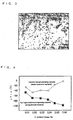
- Fig. 3 shows as an example of an electron microscopic photograph of replica extracted from steels in which M3C type carbides are finely dispersed in precipitation by air-cooling the steel after the solution treatment. In this case, the basic composition comprises 0.06 % C - 11 % Cr - 2 % Ni - Fe.
- Fig. 4 is a diagram showing the toughness in two cases of carbide precipitation for steel having a basic composition of 11 % Cr - 2% Ni - Fe: In one case M3C type carbides being finely dispersed and in the other case no carbides being precipitated, where the abscissa indicates the carbon content (mass %) and the ordinate indicates the fracture appearance transition temperature vTrs (°C). Moreover, two different steels were prepared: The first includes M3C type carbides finely dispersed in precipitation and was prepared by air-cooling (cooling at room temperature) after the solution treatment, whereas the second includes no carbides and was prepared by quick chilling (water-cooling) after the solution treatment.
- As can be seen in this diagram, a great difference can be found in the toughness at each specified amount of the carbon content between the first and second steels, and the toughness is more desirable in the first steel (mark ■ in the diagram) than in the second steel (mark □ in the diagram).
- In addition, it is found that there are no δ ferrites either in the first steel or in the second steel and therefore the carbides influence on the toughness in the martensite.
- Moreover, a study for the component of the carbides revealed that M in an M23C6 type carbide was mainly Cr whereas M in an M3C type carbide was mainly Fe, and that no corrosion resistance was reduced even when the carbides were precipitated, so long as they were of M3C type.
- On the basis of the above findings, a further detailed study was made as for the influence of the carbides on the toughness in martensitic stainless steels. As a result, it has been recognized that the toughness can be improved so long as the metallurgical structure satisfies the following conditions:
- The carbides precipitated inside grains do not provide a marked reduction in the toughness, whereas a greater amount of carbides precipitated in old or former austenite grain boundaries provide a great reduction in the toughness. When the amount of carbides in the old austenite grain boundaries is not more than 0.5 volume %, the toughness does not reduce, but rather increases irrespective of the type of carbides.
- It is noted that the toughness is also influenced by the size of the carbide, that is, an increase in the size reduces the toughness. However, finely dispersed carbides provide an increase in the toughness, compared with that in the state in which there is no carbide. More specifically, the carbides having the maximum length of 10 to 200 nm in the direction of the minor axis greatly improve the toughness.
- Moreover, the toughness is influenced by the composition of the carbides. In fact, a too high value of an average Cr concentration [Cr] reduces the toughness. On the other hand, the toughness is greatly improved when the ratio ([Cr]/[Fe]) of the average Cr concentration [Cr] to the average Fe concentration [Fe] in the steel is not more than 0.4.
- Moreover, the toughness is influenced by the quantity of M23C6 type carbides, the quantity of M3C type carbides and the quantity of MN type or M2N type nitrides. An inadequate selection of the quantities of these type carbides and nitrides results in a decreased toughness. More specifically, if a quantity of M23C6 type carbides is not more than 1 volume %; a quantity of M3C type carbides is 0.01 to 1.5 volume %; and a quantity of MN type or M2N type nitrides is not more than 0.3 volume %, the toughness is greatly improved.
- In conjunction with the above, the old austenite grain boundaries described herein mean the grain boundaries in the austenite state, which corresponds to the structure prior to the martensite transformation.
- In accordance with the present invention, the following martensitic stainless steels (1) to (4) are realized based on the above knowledge:
- (1) A martensitic stainless steel including C: 0.01 to 0.1 %, Cr: 9 to 15 %, and N: not more than 0.1 % in mass, wherein the quantity of carbides inside the old austenite grain boundaries in the steel is not more than 0.5 volume %.
- (2) A martensitic stainless steel including C: 0.01 to 0.1 %, Cr: 9 to 15 %, and N: not more than 0.1 % in mass, wherein the maximum length of the carbides in the steel is 10 to 200 nm in the direction of the minor axis.
- (3) A martensitic stainless steel including C: 0.01 to 0.1 %, Cr: 9 to 15 %, and N: not more than 0.1 % in mass, wherein the ratio ([Cr]/[Fe]) of the average Cr concentration [Cr] to the average Fe concentration [Fe] in the steel is not more than 0.4.
- (4) A martensitic stainless steel including C: 0.01 to 0.1 %, Cr: 9 to 15 %, and N: not more than 0.1 % in mass, wherein the quantity of M23C6 type carbides in the steel is not more than 1 volume %, the quantity of M3C type carbides is 0.01 to 1.5 volume % and the quantity of MN type or M2N type nitrides is not more than 0.3 volume % in the steel.
- It is preferable that, aside from the above-specified quantities of C, Cr and N, the above-mentioned martensitic stainless steels (1) to (4) include Si: 0.05 to 1 %, Mn: 0.05 to 1.5%, P: not more than 0.03 %, S: not more than 0.01 %, Ni: 0.1 to 7.0 %, Al: 0.0005 to 0.05 % in mass, and the residual comprises Fe and impurities.
- Moreover, the elements in not less than one of the following groups A, B and C can be included in the martensitic stainless steels according to the present invention:
- Group A: not less than one of Mo: 0.05 to 5 % and Cu: 0.05 to 3 %.
- Group B: not less than one of Ti: 0.005 to 0.5 %, V: 0.005 to 0.5 % and Nb: 0.005 to 0.5 %.
- Group C: not less than one of B: 0.0002 to 0.005 %, Ca: 0.0003 to 0.005 %,
Mg: 0.0003 to 0.005 % and rare-earth elements: 0.0003 to 0.005 %. -
- Fig. 1 is a diagram showing the relationship between the tempering temperature and the fracture appearance transition temperature vTrs in steel having a basic composition of 11 % Cr - 2 % Ni - Fe steel in the carbon contents of 0.20 %, 0.11 % and 0.008 %.
- Fig. 2 is an example of an electron microscopic photograph for an extraction replica of a steel having a basic composition of 0.20 % C - 11 % Cr - 2 % Ni - Fe in which coarse M23C6 type carbides are precipitated.
- Fig. 3 is an example of an electron microscopic photograph for an extraction replica of a steel having a basic composition of 0.06 % C - 11 % Cr - 2 % Ni - Fe in which fine M3C type carbides are precipitated.
- Fig. 4 is a diagram showing the relationship between the carbon content and the fracture appearance transition temperature vTrs in the cases of finely precipitated M3C type carbides and of no precipitated carbides.
- In the following, the martensitic stainless steel according to the present invention will be described in detail as for the reason why the chemical composition and metallurgical structure are specified as above. Hereinafter, "%" means "mass %" unless a special limitation is given.
- Carbon comprises an austenite-generating element, and therefore C may be included in a concentration of not less than 0.01 %, since the concentration of Ni, which also comprises another element of generating austenite, may be reduced by adding C into steel. However, a carbon concentration of more than 0.1 % reduces the corrosion resistance under a corrosion environment containing CO2 or the like. Accordingly, the carbon concentration is set to be 0.01 to 0.1 %. In this case, it is preferable that the carbon content should be set to be not less than 0.02 % in order to reduce the Ni content, it ranges preferably from 0.02 to 0.08 %, and more preferably from 0.03 to 0.08 %.
- Cr is a basic element for generating the martensitic stainless steel according to the present invention. Cr is a very important element for ensuring the corrosion resistance, the stress corrosion crack resistance and the like under a very server corrosion environment containing CO2, Cl-, H2S and the like. Moreover, an appropriate Cr concentration provides a stable metallurgical structure in the martensite. In order to obtain the above effects, Cr has to be included in a concentration of not less than 9 %. However, a Cr concentration of more than 15 % causes ferrites to generate in the metallurgical structure of the steel, thereby making it difficult to obtain maretensite structure, even when the hardening treatment is carried out. As a result, the Cr content should be set to be 9 to 15 %. It ranges preferably from 10 to 14 %, and more preferably from 11 to 13 %.
- N is an austenite-generating element and serves as an element for reducing the Ni content in the same way as C. However, an N content of more than 0.1 % reduces the toughness. As a result, the N content should be set to be not more than 0.1 %. It should be preferably not more than 0.08 %, and more preferably not more than 0.05 %.
- In the martensitic stainless steel according to the present invention, it is necessary to satisfy the following condition a or condition b or condition c or condition d, as described above:
- Condition a: The amount of carbides in old austenite grain boundaries is not more than 0.5 volume %.
- Condition b: The maximum length of carbides dispersed inside grains is 10 to 200 nm in the direction of the minor axis.
- Condition c: The ratio ([Cr]/[Fe]) of the average Cr concentration [Cr] to the average Fe concentration [Fe] in carbides in the steel is not more than 0.4.
- Condition d: The quantity of M23C6 type carbides in the steel is not more than 1 volume %, the quantity of M3C type carbides in the steel is 0.01 to 1.5 volume % and the quantity of MN type or M2N type nitrides in the steel is not more than 0.3 volume %.
- In other words, carbides, in particular M23C6 type carbides precipitate preferentially in the old austenite grain boundaries, thereby reducing the toughness of the steel. When the amount of carbides in the old austenite grain boundaries exceeds 0.5 volume %, the toughness no longer increases. In accordance with the invention, therefore, the amount of carbides in the old austenite grain boundaries is specified to be not more than 0.5 volume %. It should be set preferably to be not more than 0.3 volume % and more preferably to be not more than 0.1 volume %. In this case, it is most desirable that no carbides reside in the old austenite grain boundaries. For this reason, no lower limit can be specified in the carbide concentration.
- Coarse carbides reduce the toughness of the steel. However, finely dispersed carbides having the maximum length of not less than 10 nm in the direction of the minor axis increases the toughness, compared with that in the state in which no carbides exist in grains. On the other hand, carbides having the maximum length of more than 200 nm provide no improvement in the toughness. In the present invention, therefore, it is preferable that the maximum length of the carbides in the steel is 10 to 200 nm in the direction of the minor axis. The upper limit of the maximum length should be set to be preferably 100 nm, and more preferably 80 nm.
- When the ratio ([Cr]/[Fe]) of the average Cr concentration [Cr] to the average Fe concentration [Fe] in carbides in the steel exceeds 0.4, the toughness no longer increases and the corrosion resistance decreases. In the present invention, therefore, it is preferable that the ratio ([Cr]/[Fe]) of the average Cr concentration [Cr] to the average Fe concentration [Fe] in carbides in the steel is not more than 0.4. The ratio should be set to be preferably not more than 0.3, and more preferably not more than 0.15. In this case, a smaller magnitude of the above concentration ratio ([Cr]/[Fe]) is correspondingly more preferable, so that no lower limit is given.
- When M23C6 type carbides, M3C type carbides and MN type or M2N type nitrides in the steel are included respectively at concentrations of more than 1 volume %, less than 0.01 volume % or more than 1.5 volume %, and more than 0.3 volume % in a steel, no toughness increases. In the present invention, therefore, it is preferable that the quantities of the M23C6 type carbides, M3C type carbides, and MN type or M2N type nitrides in the steel are not more than 1 volume %, 0.01 to 1.5 volume % and not more than 0.3 volume %, respectively.
- In accordance with the invention, the upper limit of the content of M23C6 type carbides should be preferably 0.5 volume %, and more preferably 0.1 volume %, the range of the content of M3C type carbides should be preferably 0.01 to 1 volume %, and more preferably 0.01 to 0.5 volume %, and the upper limit of the content of MN type or M2N type nitrides should be preferably 0.2 volume % and more preferably 0.1 volume %. In this case, smaller amounts of both M23C6 type carbides and MN type or M2N type nitrides correspondingly provide better results. Hence, no lower limit can be given for the amount of both the M23C6 type carbides and the MN type or M2N type nitrides.
- The amount (volume rate) of the carbides inside the old austenite grain boundaries under the condition a means the magnitude determined from the following procedures: An extraction replica specimen was prepared, and an electron microscopic images was taken at a magnification of 2,000 for each of randomly selected ten fields each having a specimen area of 25 µm × 35 µm. By counting the spot array shaped carbides precipitated along old austenite grain boundaries, taking the area of the carbide spots into account, an averaged area rate of the carbides was determined from the ten fields.
- Furthermore, the maximum length of a carbide particle in the direction of the minor axis under the condition b means the magnitude determined from the following procedures: An extraction replica specimen was prepared, and an electron microscopic image was taken at a magnification of 10,000 for each of randomly selected ten fields each having a specimen area of 5 µm × 7 µm. The minor and major axes of respective carbides in each micrograph were measured by using the image analysis, and then the maximum length was determined from the longest length in the direction of the minor axis among the carbides in all the fields.
- Furthermore, the ratio ([Cr]/[Fe]) of the average Cr concentration [Cr] to the average Fe concentration [Fe] in carbides in the steel under the condition c means the ratio of Cr and Fe contents (at mass %), which are determined by chemical analysis of the extraction residual.
- Furthermore, the quantities (volume rates) of M23C6 type carbides, M3C type carbides and MN type or M2N type nitrides in the steel under the condition d mean the magnitudes determined from the following procedures: An extraction replica specimen was prepared, and an electron microscopic image was taken at a magnification of 10,000 for each of randomly selected ten fields each having a specimen area of 5 µm × 7 µm. By using the electron diffraction method or the EDS element analysis method, each carbide particle in respective fields was identified as to whether it belongs to M23C6 type carbide or to M3C type carbide and to MN type or M2N type nitride. Thereafter, the area rates of the respective carbides and nitride for ten fields were determined, using the image analysis and then averaged to obtain the quantities.
- Regarding the heat treatments for obtaining the metallurgical structure satisfying the above condition a or the condition b or the condition c or the condition d, there is no special restriction, so long as the heat treatments provide a metallurgical structure which can be obtained under any one of the above-mentioned conditions. However, the tempering at a high temperature, more specifically the tempering at a temperature of more than 500 °C, which is conventionally employed in the heat treatments for the martensitic stainless steels, should not be carried out in the present invention. This is because the tempering at a temperature of more than 500 °C provides a greater number of M23C6 type carbides for the martensitic stainless steel including such a great amount of Cr and C as in the present invention.
- The structure under any one of the above conditions can readily be obtained by appropriately adjusting the conditions of quenching or tempering in the production in accordance with the chemical composition of the steel (for instance, the conditions shown in the embodiments hereinafter described). For instance, heat treatments for obtaining a finely dispersed precipitation of M3C type carbides are exemplified as follows:
- After hot working, a martensitic stainless steel having predetermined contents of C, Cr and N, their ranges being specified by the present invention, either is quenched (water-cooling) and then tempered at 300 to 450 °C, or is cooled in air (cooling at room temperature). Alternately, the steel is heated up to the transformation temperature AC3 to form austenite phase (solid solution treatment), and then the steel is either cooled in air (cooling at room temperature) or tempered at a low temperature of 300 to 450 °C.
- The martensitic stainless steel according to the present invention provides an excellent property regarding the toughness, so long as the above-described chemical composition and the metallurgical structure are satisfied. In this case, it is desirable that, regarding the chemical composition, the contents of Si, Mn, P, S, Ni and Al are within the respective ranges described in the following, and the residual substantially comprises Fe.
- Si serves as an element effective for deoxidizing. However, a Si content of less than 0.05 % provides a greater loss of Al in the process of deoxidizing, whereas a Si content of more than 1 % provides a decreased toughness for the steel. Accordingly, it is desirable that the Si content is set to be 0.05 to 1 %. The range of the content should be preferably 0.1 to 0.5 %, and more preferably 0.1 to 0.35 %.
- Mn serves as an element effective for enhancing the strength of the steel, and further is an austenite-generating element: The element is effectively used to stabilize the metallurgical structure and to form martensite by the quenching hardening treatment. Regarding the latter, the Mn content of less than 0.05 % provides a very small effect whereas the Mn content of more than 1.5 % provides a saturated effect. Hence, it is desirable that the Mn content is set to be 0.05 to 1.5 %. The range of the content should be preferably 0.1 to 1.0 % and more preferably 0.1 to 0.8 %.
- P is an impurity element and provides an very harmful influence on the toughness of the steel, and at the same time reduces the corrosion resistance in the corrosion environment containing CO2 and others. A smaller P content is correspondingly more desirable. However, there is no special problem at a P content of 0.03 % or less. Accordingly, the P content should be preferably not more than 0.02 %, and more preferably not more than 0.015 %.
- S is an impurity element, in the same way as P, and provides a very harmful influence on the hot workability of the steel. Therefore, a smaller content of S is correspondingly more desirable. However, there is no special problem at a S content of 0.01 % or less. Accordingly, the S content should be preferably not more than 0.005 % and more preferably not more than 0.003 %.
- Ni is an element for producing austenite, and has an effect to stabilize the metallurgical structure and to form martensite by the quenching hardening treatment. Moreover, Ni plays an essential role for ensuring to maintain the corrosion resistance, the stress corrosion crack resistance and the like in a severe corrosion environment containing CO2, Cl-, H2S and the like. A Ni content of not less than 0.1 % is required to obtain the above-mentioned effects. When, however, the content becomes more than 7.0 %, the production cost significantly increases. Accordingly, it is desirable that the Ni content ranges from 0.1 to 7.0 %. The range should be preferably 0.1 to 3.0 % and more preferably 0.1 to 2.0%.
- Al serves as an element effective for deoxidizing. For this purpose, an Al content of not less than 0.0005 % is required. On the other hand, an Al content of more than 0.05 % reduces the toughness. Accordingly, it is desirable that the Al content ranges from 0.0005 to 0.05 %. The range should be preferably 0.005 to 0.03 %, and more preferably 0.01 to 0.02 %.
- In addition, (an) element(s) in at least one of group A, group B and group C, which are described below, can be included in the above-mentioned preferable martensitic stainless steels:
- These elements improve the corrosion resistance in the corrosion environment containing CO2 and Cl-, and a marked effect can be obtained at the Mo or Cu content of not less than 0.05 %. However, either a Mo content of more than 5 % or a Cu content of more than 3 % provides not only saturation on the above effects, but also a reduction in the toughness at the area suffered by the heat effect due to welding. It is therefore desirable that the Mo content and the Cu content are set to be 0.05 to 5 % and 0.05 to 3 %, respectively. The range for Mo should be preferably 0.1 to 2 %, and more preferably 0.1 to 0.5 % whereas the range for Cu should be preferably 0.05 to 2.0 % and more preferably 0.05 to 1.5 %.
- Each of these elements improves the stress corrosion crack resistance in the corrosion environment containing H2S, and, at the same time, increases the tensile strength at a high temperature. A content of not less than 0.005 % for each element provides a prominent effect on the above properties. However, a content of more than 0.5 % for each element causes the toughness to deteriorate. It is therefore desirable that. the content of each element ranges from 0.005 to 0.5 %. The range should be preferably 0.005 to 0.2 %, and more preferably 0.005 to 0.05 %.
- Each of these elements improves the hot workability, and a prominent effect can be obtained at a content of not less than 0.0002 % for B, or at a content of not less than 0.0003 % for Ca, Mg or a rare-earth element. However, a content of more than 0.005 % for each element provides a reduction not only in the toughness, but also in the corrosion resistance under the corrosion environment containing CO2 and the like. Therefore, it is desirable that the content is 0.0002 to 0.005 % for B, 0.0003 to 0.005 % for Ca, Mg or a rare-earth element. The range for any element should be preferably 0.0005 to 0.0030 %, and more preferably 0.0005 to 0.0020 %.
- Five kinds of steel blocks (thickness 70 mm and width 120 mm) having a chemical composition different from each other, as shown in Table 1 were prepared. The steels having such a chemical composition different from each other were molten in a vacuum-melting furnace having a capacity of 150 kg. The respective ingots thus obtained were heated for 2 hours at 250 °Cand then forged into a predetermined shape.
- Each block was heated for one hour at 1,250 °C, and then hot-rolled to form a steel plate having a thickness of 7 to 50 mm. In this case, two type steel plates, one satisfying and the other unsatisfying the above condition a, were prepared by varying both the temperature in the hot-rolling and the heat treatment conditions. Applying a tensile test, a Charpy impact test and a corrosion test to these steel plates, the tensile properties (yield strength: YS (MPa) and tensile strength: TS (MPa)), the impact property (fracture appearance transition temperature: vTrs (°C)) and the corrosion property were investigated.
- The tensile test was carried out as for 4 mm diameter rod specimens machined from the respective steel plates after the heat treatment.

- The Charpy impact test was carried out as for 2 mm V-shaped notch test pieces having a sub-size of 5 mm × 10 mm × 55 mm, which were machined from the respective steel plates after the heat treatment.
- The corrosion test was carried out by immersing coupon test pieces having a size of 2 mm × 10 mm × 25 mm into an aqueous solution of 0.003 atm H2S (0.0003 MPa H2S) - 30 atm CO2 (3 MPa CO2) - 5 mass % NaCl for 720 hours, said test pieces being machined from the respective steel plates after the heat treatment. In the evaluation of the corrosion resistance, test pieces exhibiting a corrosion speed of not more than 0.05 g/m2/hr and those exhibiting a corrosion speed of more than 0.05 g/m2/hr are classified as a good ones (○) and bad ones (×), respectively.
- The results in EXAMPLE 1 are again listed in Table 2, together with the finishing temperatures in the hot rolling, the heat treatments and the quantities of carbides in the old austenite grain boundaries, which were determined by the above-mentioned method.
Table 2 Test piece No. Steel type symbols Finishing temperature in hot rolling (°C) Treatments after hot rolling (heat treatments) Plate thickness (mm) Amount of carbides in old austenite grain boundaries (vol. %) Tensile properties Impact property vTrs (°C) Corrosion resistance YS
(MPa)TS
(MPs)1 A 1,040 WQ 50 0 823 1,066 -40 ○ AC+ 2 A 1,050 950°C × 15minAC+ 50 *0.6 733 974 -11 × 650°C × 30minAC 3 B 950 WQ 25 0 854 1,071 -49 ○ AC+ 4 B 950 950°C × 15minAC+ 25 *0.7 819 1,033 -2 × 650°C × 30minAC AC+ 5 C 830 15minAC 950°C × 7 0.05 993 1,188 -35 ○ AC+ 6 C 850 970°C × 15minAC+ 7 *1 952 1,148 21 × 650°C × 30minAC AC+ 7 D 1,000 1,000°C × 15minAC 30 0.1 980 1,222 -31 ○ AC+ 8 D 1,020 1,000°C × 15minAC+ 30 *1.2 943 1,159 32 × 650°C × 30minAC 9 E 960 WQ 12 0 810 1,069 -41 ○ AC+ 10 E 980 940°C × 15minAC+ 12 *0.9 756 1,001 -10 × 650°C × 30minAC Notes: 1) AC means air cooling (cooling at room temperature) and WQ means water cooling.
2) Mark
* indicates the outside of the range specified by the invention. - As can be clearly seen in Table 2, the steel plates corresponding to test pieces No. 1, 3, 5, 7 and 9, in which the metallurgical structure satisfies the above condition a specified in the present invention, are excellent regarding the strength, the toughness and the corrosion resistance. On the contrary, the steel plates corresponding to test pieces No. 2, 4, 6, 8 and 10, in which the metallurgical structure does not satisfy the above condition a specified by the present invention, but the chemical composition satisfies the condition a specified by the present invention, are unsatisfactory regarding both the toughness and corrosion resistance, although a high strength can be obtained.
- Each block was heated for one hour at 1,250 °C, and then hot-rolled to form a steel plate having a thickness of 7 to 50 mm. In this case, two type steel plates, one satisfying and the other unsatisfying the above condition b, were prepared by varying both the temperature in the hot rolling and the heat treatment conditions. Applying a tensile test, a Charpy impact test and a corrosion test to these steel plates, the tensile properties (yield strength: YS (MPa) and tensile strength: TS (MPa)), the impact property (fracture appearance transition temperature: vTrs (°C)) and the corrosion property were investigated.
- In this case, the tensile test, the Charpy impact test and the corrosion test and the evaluation thereof were the same as those in the case of EXAMPLE 1.
- The obtained results are listed in Table 3, together with the finishing temperatures in the hot rolling, the heat treatments and the maximum lengths of the carbides in the direction of the minor axis, which were determined by the above-mentioned method.
Table 3 Test piece No. Steel type symbols Finishing temperature in hot rolling
(°C)Treatments after hot rolling
(heat treatments)Plate thickness
(mm)Maximum length of carbide in the direction of the minor axis (nm) Tensile properties Impact property vTrs
(°C)Corrosion resistance YS
(MPa)TS
(MPa)11 A 1,010 AC+
920°C × 15minWQ+
350°C × 30minAC50 33 808 1,053 -51 ○ 12 A 1,020 AC+
920°C × 15min AC+
650°C × 30minAC50 *350 727 979 -9 × 13 B 950 WQ+
930°C × 15minWQ+
420°C × 30minAC25 50 852 1,078 -50 ○ 14 B 940 AC+
930°C × 15minAC+
650°C × 30minAC25 *420 810 1,037 -6 × 15 C 990 AC+
950°C × 15minWQ+
380°C × 30minAC18 42 984 1,193 -60 ○ 16 C 980 AC+
950°C × 15minAC+
650°C × 30minAC18 *520 950 1,155 18 × 17 D 930 AC+
980°C × 15minWQ+
360°C × 30minAC10 38 985 1,208 -61 ○ 18 D 930 AC+
980°C × 15minAC+
650°C × 30minAC10 *340 942 1,159 28 × 19 E 890 AC+
920°C × 15minWQ+
400°C × 30minAC7 45 791 1,074 -53 ○ 20 E 870 AC+
920°C × 15minAC+
650°C × 30minAC7 *310 765 1,003 -8 × Notes: 1) AC means air cooling (cooling at room temperature) and WQ means water cooling.
2) Mark * indicates the outside of the range specified by the invention. - As can be clearly seen in Table 3, the steel plates corresponding to the test pieces No. 11, 13, 15, 17 and 19, in which the metallurgical structure satisfies the condition b specified by the present invention, are excellent regarding the strength, the toughness and the corrosion resistance. On the contrary, the steel plates corresponding to the test pieces No. 12, 14, 16, 18 and 20, in which the metallurgical structure does not satisfy the condition b specified by the present invention, but the chemical composition satisfies the condition specified by the present invention, are unsatisfactory regarding the toughness and the corrosion resistance, although a high strength can be obtained.
- Each block was heated for one hour at 1,250 °C, and then hot-rolled to form a steel plate having a thickness of 8 to 25 mm. In this case, two type steel plates, one satisfying and the other unsatisfying the above condition c, were prepared by varying both the temperature in the hot rolling and the heat treatment conditions. Applying a tensile test, a Charpy impact test and a corrosion test to these steel plates, the tensile properties (yield strength: YS (MPa) and tensile strength: TS (MPa)), the impact property (fracture appearance transition temperature: vTrs (°C)) and the corrosion property were investigated.
- In this case, the tensile test, the Charpy impact test and the corrosion test and the evaluation thereof were the same as those in the case of EXAMPLE 1.
- The obtained results are listed in Table 4, together with the finishing temperatures in the hot rolling, the heat treatments and the ratios of the average Cr concentration to the average Fe concentration in the carbides, which were determined by the above-mentioned method.
Table 4 Test piece No. Steel type in symbols Finishing temperature hot rolling
(°C)Treatments after hot rolling (heat treatments) Plate thickness
(mm)Average Cr concentration /average Fe concentration in carbide Tensile properties Impact property vTrs
(°C)Corrosion resistance YS
(MPa)TS
(MPa)21 A 900 AC+
280°C × 30minAC12 0.11 843 1,063 -83 ○ 22 A 900 AC+
910°C × 15minAC+
650°C × 30minAC12 *0.58 729 979 -13 × 23 B 950 AC+
320°C × 30minAC25 0.13 867 1,088 -81 ○ 24 B 960 AC+
940°C × 15minAC+
650°C × 30minAC25 *0.65 820 1,035 3 × 25 C 920 AC+
280°C × 30minAC12 0.10 988 1,183 -78 ○ 26 C 920 AC+
960°C × 15minAC+
650°C × 30minAC12 *0.82 949 1,141 15 × 27 D 800 AC+
1,030°C × 15minAC8 0.11 1,002 1,228 -92 ○ 28 D 800 AC+
1,020°C × 15minAC+
650°C × 30minAC8 *0.79 951 1,158 22 × 29 E 800 AC 20 0.11 783 1,065 -91 ○ 30 E 990 AC+
950°C × 15minAC+
650°C ×30minAC 20 *0.68 757 1,001 -5 × Notes: 1) AC means air cooling (cooling at room temperature).
2) Mark * indicates the outside of the range specified by the invention. - As can be clearly seenin Table 4, the steel plates corresponding to the test pieces No. 21, 23, 25, 27 and 29, in which the metallurgical structure satisfy the condition c specified by the present invention, are excellent regarding the strength, the toughness and the corrosion resistance. On the contrary, the steel plates corresponding to the test pieces No. 22, 24, 26, 28 and 30, in which the metallurgical structure does not satisfy the condition c specified by the present invention, but the chemical composition satisfies the condition specified by the present invention, are unsatisfactory regarding the toughness and the corrosion resistance, although a high strength can be obtained.
- Each block was heated for one hour at 1,250 °C, and then hot-rolled to form a steel plate having a thickness of 14 to 25 mm. In this case, two type steel plates, one satisfying and the other unsatisfying the above condition d, were prepared by varying both the temperature in the hot rolling and the heat treatment conditions. Applying a tensile test, a Charpy impact test and a corrosion test to these steel plates, the tensile properties (yield strength: YS (MPa) and tensile strength: TS (MPa)), the impact property (fracture appearance transition temperature: vTrs (°C)) and the corrosion property were investigated.
- In this case, the tensile test, the Charpy impact test and the corrosion test and the evaluation thereof were the same as those in the case of EXAMPLE 1.
- The obtained results are listed in Table 5, together with the finishing temperatures in the hot rolling, the heat treatments and the contents of M23C6 type carbides, M3C type carbides and MN type or M2N type nitrides, which were determined by the above-mentioned method.
Table 5 Test piece No. Steel type symbols Finishing temperature in hot rolling (°C) Treatments after hot rolling (heat treatments) Plate thickness (mm) Conten t of M23C6 type carbides (vol. %) Conten t of M3C type carbides (vol. %) Content of MN type or M2N type nitrides (vol. %) Tensile properties Impact property vTrs (°C) Corrosion resistance YS
(MPa)TS
(MPa)31 A 990 AC+
900°C ×15minAC 20 0 0.08 0 825 1,057 -81 ○ 32 A 1,000 AC+
910°C × 15minAC+
650°C ×30minAC 20 0.6 *0 0.21 742 967 -3 × 33 B 1,000 AC+
960°C × 15minAC25 0 0.12 0 853 1,073 -96 ○ 34 B 1,020 AC+
940°C × 15minAC+
650°C × 30minAC25 0.8 *0 0.22 817 1,024 2 × 35 C 900 AC+
980°C × 15minAC14 0 0.18 0 988 1,188 -92 ○ 36 C 890 AC+
970°C × 15minAC+
650°C × 30minAC14 *1.2 *0 0.03 948 1,151 20 × 37 D 1,000 AC 22 0 0.45 0 989 1,219 -98 ○ 38 D 1,020 AC+
1,030°C × 15minAC+
650°C × 30minAC22 *1.4 *0 0.09 946 1,154 26 × 39 E 940 AC+
300°C × 30minAC15 0 0.11 0 796 1,069 -78 ○ 40 E 950 AC+
900°C × 15minAC+
650°C × 30minAC15 0 *0 *0.34 758 993 -6 × Notes: 1) AC means air cooling (cooling at room temperature).
2) Mark * indicates the outside of the range specified by the invention. - As can be clearly seen in Table 5, the steel plates corresponding to the test pieces No. 31, 33, 35, 37 and 39, in which the metallurgical structure satisfy the condition d specified by the present invention, are excellent regarding the strength, the toughness and the corrosion resistance. On the contrary, the steel plates corresponding to the test pieces No. 32, 34, 36, 38 and 40, in which the metallurgical structure does not satisfy the condition d specified by the present invention, but the chemical composition satisfies the condition specified by the present invention, are unsatisfactory regarding the toughness and the corrosion resistance, although a high strength can be obtained.
- The martensitic stainless steel according to the present invention provides excellent properties regarding the toughness and the corrosion resistance, in spite of both a relatively high carbon content and a high strength, and therefore it can be used effectively as a pipe material for oil wells, in particular for oil wells having a much greater depth. The reduction of the carbon content as required in the conventional improved 13 % Cr steels is no longer necessary. This causes to reduce the content of Ni which is expensive, so that the production cost can also be reduced. A wide applicability can be expected to pipe material for oil wells containing carbon dioxide and a very small amount of hydrogen sulfide, in particular for oil wells having a much greater depth.
Claims (8)
- A martensitic stainless steel having a C content of 0.01 to 0.1 mass %, a Cr content of 9 to 15 mass % and a N content of not more than 0.1 mass %, wherein the content of carbides inside old austenite grain boundaries in the steel is not more than 0.5 volume %.
- A martensitic stainless steel having a C content of 0.01 to 0.1 mass %, a Cr content of 9 to 15 mass % and a N content of not more than 0.1 mass %, wherein the maximum length of the carbides in the steel is 10 to 200 nm in the direction of the minor axis.
- A martensitic stainless steel having a C content of 0.01 to 0.1 mass %, a Cr content of 9 to 15 mass % and a N content of not more than 0.1 mass %, wherein the ratio ([Cr]/[Fe]) of the average Cr concentration [Cr] to the average Fe concentration [Fe] in carbides in the steel is not more than 0.4.
- A martensitic stainless steel having a C content of 0.01 to 0.1 mass %, a Cr content of 9 to 15 mass % and a N content of not more than 0.1 mass %, wherein the content of M23C6 type carbides in the steel is not more than 1 volume %, the content of M3C type carbides in the steel is 0.01 to 1.5 volume % and the content of MN type or M2N type nitrides in the steel is not more than 0.3 volume %.
- A martensitic stainless steel according to one of Claims 1 to 4, wherein in addition of the above three components, the stainless steel further includes a Si content of 0.05 to 1 mass %, a Mn content of 0.05 to 1.5 mass %, a P content of not more than 0.03 mass %, a S content of not more than 0.01 mass %, an Ni content of 0.1 to 7.0 mass % and an Al content of 0.0005 to 0.05 mass %, the residual being Fe and impurities.
- A martensitic stainless steel according to Claim 5, wherein in place of part of Fe, the stainless steel includes at least one of Mo and Cu at a content of 0.05 to 5 mass % and at a content of 0.05 to 3 mass %, respectively.
- A martensitic stainless steel according to Claim 5 or 6, wherein in place of part of Fe, the stainless steel includes at least one of Ti, V and Nb at a content of 0.005 to 0.5 mass %, at a content of 0.005 to 0.5 mass % and at a content of 0.005 to 0.5 mass %, respectively.
- A martensitic stainless steel according to one of Claims 5 to 7, wherein in place of part of Fe, the stainless steel includes at least one of B, Ca, Mg and rare-earth elements at a content of 0.0002 to 0.005 mass %, at a content of 0.0003 to 0.005 mass %, at a content of 0.0003 to 0.005 mass % and at a content of 0.0003 to 0.005 mass %, respectively.
Applications Claiming Priority (3)
| Application Number | Priority Date | Filing Date | Title |
|---|---|---|---|
| JP2001167046A JP4240189B2 (en) | 2001-06-01 | 2001-06-01 | Martensitic stainless steel |
| JP2001167046 | 2001-06-01 | ||
| PCT/JP2002/005399 WO2002099150A1 (en) | 2001-06-01 | 2002-05-31 | Martensitic stainless steel |
Publications (3)
| Publication Number | Publication Date |
|---|---|
| EP1403391A1 true EP1403391A1 (en) | 2004-03-31 |
| EP1403391A4 EP1403391A4 (en) | 2004-08-25 |
| EP1403391B1 EP1403391B1 (en) | 2006-10-25 |
Family
ID=19009488
Family Applications (1)
| Application Number | Title | Priority Date | Filing Date |
|---|---|---|---|
| EP02728217A Expired - Lifetime EP1403391B1 (en) | 2001-06-01 | 2002-05-31 | Martensitic stainless steel |
Country Status (13)
| Country | Link |
|---|---|
| US (1) | US7361236B2 (en) |
| EP (1) | EP1403391B1 (en) |
| JP (1) | JP4240189B2 (en) |
| CN (1) | CN1255569C (en) |
| AT (1) | ATE343656T1 (en) |
| AU (1) | AU2002258259B2 (en) |
| BR (1) | BR0210908B1 (en) |
| CA (1) | CA2448882C (en) |
| CZ (1) | CZ300026B6 (en) |
| DE (1) | DE60215655T2 (en) |
| MX (1) | MXPA03011036A (en) |
| NO (1) | NO336990B1 (en) |
| WO (1) | WO2002099150A1 (en) |
Cited By (1)
| Publication number | Priority date | Publication date | Assignee | Title |
|---|---|---|---|---|
| CN104882678A (en) * | 2015-05-22 | 2015-09-02 | 深圳市华讯方舟科技有限公司 | Ka-band parabolic antenna heat treatment method |
Families Citing this family (30)
| Publication number | Priority date | Publication date | Assignee | Title |
|---|---|---|---|---|
| AU2004258030B2 (en) | 2003-07-22 | 2008-08-28 | Nippon Steel Corporation | Martensitic stainless steel |
| FR2872825B1 (en) * | 2004-07-12 | 2007-04-27 | Industeel Creusot | MARTENSITIC STAINLESS STEEL FOR MOLDS AND CARCASES OF INJECTION MOLDS |
| JP5145793B2 (en) * | 2007-06-29 | 2013-02-20 | Jfeスチール株式会社 | Martensitic stainless steel seamless pipe for oil well pipe and method for producing the same |
| CN102144041B (en) | 2008-09-04 | 2014-05-14 | 杰富意钢铁株式会社 | Seamless pipe of martensitic stainless steel for oil well pipe and process for producing same |
| CH700482A1 (en) * | 2009-02-19 | 2010-08-31 | Alstom Technology Ltd | Welding additive material. |
| AR076669A1 (en) * | 2009-05-18 | 2011-06-29 | Sumitomo Metal Ind | STAINLESS STEEL FOR PETROLEUM WELLS, STAINLESS STEEL TUBE FOR PETROLEUM WELLS, AND STAINLESS STEEL MANUFACTURING METHOD FOR PETROLEUM WELLS |
| CN102839331B (en) * | 2011-06-24 | 2014-10-01 | 宝山钢铁股份有限公司 | High-toughness corrosion-resistant steel and manufacturing method thereof |
| JP2014205911A (en) * | 2013-03-21 | 2014-10-30 | 大日本印刷株式会社 | Stainless steel machining member and manufacturing method of stainless steel machining member |
| RU2516187C1 (en) * | 2013-04-09 | 2014-05-20 | Федеральное государственное бюджетное учреждение науки Институт металлургии и материаловедения им. А.А. Байкова Российской академии наук (ИМЕТ РАН) | High-nitrogen martensite nickel steel |
| BR102014005015A8 (en) | 2014-02-28 | 2017-12-26 | Villares Metals S/A | martensitic-ferritic stainless steel, manufactured product, process for producing forged or rolled bars or parts of martensitic-ferritic stainless steel and process for producing all seamless martensitic-ferritic stainless steel |
| JP6128291B2 (en) * | 2015-04-21 | 2017-05-17 | Jfeスチール株式会社 | Martensitic stainless steel |
| US10344758B2 (en) * | 2016-04-07 | 2019-07-09 | A. Finkl & Sons Co. | Precipitation hardened martensitic stainless steel and reciprocating pump manufactured therewith |
| KR102169859B1 (en) | 2016-04-12 | 2020-10-26 | 제이에프이 스틸 가부시키가이샤 | Martensite stainless steel plate |
| DE102016109253A1 (en) * | 2016-05-19 | 2017-12-07 | Böhler Edelstahl GmbH & Co KG | Method for producing a steel material and steel material |
| CN109890993B (en) * | 2016-10-18 | 2022-01-11 | 杰富意钢铁株式会社 | Martensitic stainless steel sheet |
| US10870900B2 (en) * | 2017-06-07 | 2020-12-22 | A. Finkl & Sons Co. | High toughness martensitic stainless steel and reciprocating pump manufactured therewith |
| CN107904487B (en) * | 2017-11-03 | 2019-11-22 | 钢铁研究总院 | A multi-element chromium molybdenum carbon dioxide corrosion resistant oil well pipe and its manufacturing method |
| RU2703767C1 (en) * | 2018-06-01 | 2019-10-22 | Публичное акционерное общество "Трубная металлургическая компания" (ПАО "ТМК") | Pipe of oil grade from corrosion-resistant steel of martensitic class |
| CN110643895B (en) * | 2018-06-27 | 2021-05-14 | 宝山钢铁股份有限公司 | Martensitic stainless steel oil casing and manufacturing method thereof |
| CN109811253A (en) * | 2018-12-21 | 2019-05-28 | 江苏星火特钢有限公司 | A kind of super martensitic stainless steel and its manufacturing process |
| CN112251685B (en) * | 2020-09-29 | 2022-05-31 | 中国科学院金属研究所 | Ultrahigh-strength nanocrystalline 12Cr13Cu4Mo stainless steel and preparation method thereof |
| CN114635075A (en) * | 2020-12-15 | 2022-06-17 | 上海电气电站设备有限公司 | High-strength high-ductility and toughness blade material |
| IT202000032417A1 (en) | 2020-12-24 | 2022-06-24 | Brembo Spa | DOUBLE LAYER STEEL BRAKE DISC WITHOUT NICKEL AND METHOD OF REALIZATION |
| KR20240125543A (en) * | 2021-12-20 | 2024-08-19 | 주식회사 포스코 | Martensitic stainless steel with improved softening resistance and its manufacturing method |
| WO2023228783A1 (en) * | 2022-05-25 | 2023-11-30 | 日本製鉄株式会社 | Martensitic stainless steel material |
| CN114921629B (en) * | 2022-07-20 | 2022-11-15 | 中北大学 | 7Cr14 martensitic stainless steel and refining process of carbide thereof |
| CN115927800A (en) * | 2022-11-29 | 2023-04-07 | 中国科学院金属研究所 | Low-carbon nitrogen-containing high-strength and high-toughness martensitic stainless steel and heat treatment method thereof |
| CN116103472B (en) * | 2022-12-07 | 2025-07-25 | 中国科学院金属研究所 | Heat treatment process for improving low-temperature toughness of low-carbon high-strength martensitic stainless steel |
| CN115976313A (en) * | 2022-12-16 | 2023-04-18 | 贵州航天新力科技有限公司 | A kind of production method of 00Cr12Ni10MoTi martensitic stainless steel forging |
| EP4726065A1 (en) * | 2024-10-10 | 2026-04-15 | Solu Stainless Oy | Martensitic stainless steel |
Family Cites Families (20)
| Publication number | Priority date | Publication date | Assignee | Title |
|---|---|---|---|---|
| CS223239B1 (en) * | 1981-05-11 | 1983-09-15 | Josef Cizner | Martensitic chrome-nickel steel |
| JPS60149715A (en) * | 1984-01-18 | 1985-08-07 | Japan Steel Works Ltd:The | Heat treatment of low-carbon martensitic stainless steel |
| DE3482772D1 (en) | 1984-10-11 | 1990-08-23 | Kawasaki Steel Co | STAINLESS STEEL MARTENSITICAL STEEL FOR SEAMLESS TUBES. |
| JPH0598347A (en) * | 1990-12-06 | 1993-04-20 | Nippon Steel Corp | Method for producing martensitic 13% Cr stainless steel excellent in toughness and stress corrosion cracking resistance |
| JP3106674B2 (en) | 1992-04-09 | 2000-11-06 | 住友金属工業株式会社 | Martensitic stainless steel for oil wells |
| JP2854249B2 (en) * | 1994-04-08 | 1999-02-03 | 新日本製鐵株式会社 | Stress sensor |
| JP3426036B2 (en) * | 1994-08-26 | 2003-07-14 | 日新製鋼株式会社 | Martensitic stainless steel excellent in strength and toughness and method for producing the same |
| KR960706569A (en) * | 1994-09-30 | 1996-12-09 | 다나카 미노루 | High corrosion resistance martensitic stainless steel with excellent weldability and manufacturing method |
| EP0770696B1 (en) * | 1995-04-12 | 1999-01-13 | Mitsubishi Jukogyo Kabushiki Kaisha | High strength and high toughness heat resisting steel and its manufacturing method |
| JP3190825B2 (en) * | 1996-06-27 | 2001-07-23 | 川崎製鉄株式会社 | Ferritic stainless steel hot-rolled steel sheet excellent in corrosion resistance, formability and material uniformity, and method for producing the same |
| DE69838879T2 (en) * | 1997-07-18 | 2008-12-04 | Sumitomo Metal Industries, Ltd. | MARTENSITIC STAINLESS STEEL WITH HIGH CORROSION RESISTANCE |
| JPH11140585A (en) * | 1997-09-05 | 1999-05-25 | Timken Co:The | Heat treated steel having optimum toughness |
| JP2002509195A (en) * | 1998-01-16 | 2002-03-26 | シーアールエス ホールディングス,インコーポレイテッド | Martensitic stainless steel for free cutting |
| JP3539250B2 (en) * | 1998-12-09 | 2004-07-07 | Jfeスチール株式会社 | 655 Nmm-2 class low C high Cr alloy oil country tubular good with high stress corrosion cracking resistance and method of manufacturing the same |
| JP2000204434A (en) * | 1999-01-13 | 2000-07-25 | Sumitomo Metal Ind Ltd | Ferritic heat-resistant steel excellent in high-temperature strength and its manufacturing method |
| JP3485034B2 (en) * | 1999-07-19 | 2004-01-13 | Jfeスチール株式会社 | 862N / mm2 Class Low C High Cr Alloy Oil Well Pipe Having High Corrosion Resistance and Method of Manufacturing the Same |
| JP2001123254A (en) * | 1999-10-22 | 2001-05-08 | Sanyo Special Steel Co Ltd | Method for producing martensitic corrosion-resistant steel without formation of reticulated carbide |
| JP2001152296A (en) * | 1999-11-26 | 2001-06-05 | Kawasaki Steel Corp | Stainless steel hot rolled steel sheet for civil and building structures with excellent workability and weldability |
| US6793744B1 (en) * | 2000-11-15 | 2004-09-21 | Research Institute Of Industrial Science & Technology | Martenstic stainless steel having high mechanical strength and corrosion |
| JP4337268B2 (en) * | 2001-02-27 | 2009-09-30 | 大同特殊鋼株式会社 | High hardness martensitic stainless steel with excellent corrosion resistance |
-
2001
- 2001-06-01 JP JP2001167046A patent/JP4240189B2/en not_active Expired - Fee Related
-
2002
- 2002-05-31 AU AU2002258259A patent/AU2002258259B2/en not_active Ceased
- 2002-05-31 BR BRPI0210908-5A patent/BR0210908B1/en not_active IP Right Cessation
- 2002-05-31 WO PCT/JP2002/005399 patent/WO2002099150A1/en not_active Ceased
- 2002-05-31 EP EP02728217A patent/EP1403391B1/en not_active Expired - Lifetime
- 2002-05-31 MX MXPA03011036A patent/MXPA03011036A/en active IP Right Grant
- 2002-05-31 DE DE60215655T patent/DE60215655T2/en not_active Expired - Lifetime
- 2002-05-31 AT AT02728217T patent/ATE343656T1/en not_active IP Right Cessation
- 2002-05-31 CN CN02811116.8A patent/CN1255569C/en not_active Expired - Fee Related
- 2002-05-31 CZ CZ20033144A patent/CZ300026B6/en not_active IP Right Cessation
- 2002-05-31 CA CA2448882A patent/CA2448882C/en not_active Expired - Fee Related
-
2003
- 2003-04-11 US US10/411,186 patent/US7361236B2/en not_active Expired - Fee Related
- 2003-11-27 NO NO20035266A patent/NO336990B1/en not_active IP Right Cessation
Cited By (2)
| Publication number | Priority date | Publication date | Assignee | Title |
|---|---|---|---|---|
| CN104882678A (en) * | 2015-05-22 | 2015-09-02 | 深圳市华讯方舟科技有限公司 | Ka-band parabolic antenna heat treatment method |
| CN104882678B (en) * | 2015-05-22 | 2017-12-15 | 深圳市华讯方舟卫星通信有限公司 | Ka wave band parabola antenna heat treatment methods |
Also Published As
| Publication number | Publication date |
|---|---|
| CN1255569C (en) | 2006-05-10 |
| ATE343656T1 (en) | 2006-11-15 |
| NO20035266L (en) | 2003-11-27 |
| MXPA03011036A (en) | 2004-03-19 |
| JP4240189B2 (en) | 2009-03-18 |
| NO20035266D0 (en) | 2003-11-27 |
| US20050274436A1 (en) | 2005-12-15 |
| AU2002258259B2 (en) | 2004-12-16 |
| JP2002363708A (en) | 2002-12-18 |
| CZ20033144A3 (en) | 2004-03-17 |
| US7361236B2 (en) | 2008-04-22 |
| EP1403391B1 (en) | 2006-10-25 |
| BR0210908B1 (en) | 2010-12-14 |
| CZ300026B6 (en) | 2009-01-14 |
| CA2448882A1 (en) | 2002-12-12 |
| CA2448882C (en) | 2010-05-25 |
| CN1582342A (en) | 2005-02-16 |
| DE60215655T2 (en) | 2007-08-23 |
| WO2002099150A1 (en) | 2002-12-12 |
| DE60215655D1 (en) | 2006-12-07 |
| BR0210908A (en) | 2004-06-08 |
| NO336990B1 (en) | 2015-12-14 |
| EP1403391A4 (en) | 2004-08-25 |
Similar Documents
| Publication | Publication Date | Title |
|---|---|---|
| EP1403391B1 (en) | Martensitic stainless steel | |
| EP1956100B1 (en) | Method of warm working of a steel material and steel material obtained by the same | |
| AU2003227225B2 (en) | Low alloy steel | |
| EP0649915B1 (en) | High-strength martensitic stainless steel and method for making the same | |
| EP2341161B1 (en) | High strength stainless steel piping having outstanding resistance to sulphide stress cracking and resistance to high temperature carbon dioxide corrosion | |
| AU2015361346B2 (en) | Low-alloy steel for oil well pipe and method for manufacturing low-alloy steel oil well pipe | |
| EP3604591A1 (en) | Martensitic stainless steel material | |
| JP2003041341A (en) | Steel material having high toughness and method for manufacturing steel pipe using the same | |
| EA012256B1 (en) | Low-alloy steel, seamless steel pipe for oil well and process for producing seamless steel pipe | |
| EP4123040A1 (en) | Stainless seamless steel pipe and method for producing stainless seamless steel pipe | |
| CN1044263C (en) | Highly corrosion-resistant martensitic stainless steel with excellent weldability and process for producing the same | |
| JP2003193204A (en) | Martensitic stainless steel | |
| EP3730656A1 (en) | Wear-resistant steel having excellent hardness and impact toughness, and method for producing same | |
| EP4123039A1 (en) | Stainless seamless steel pipe and method for producing stainless seamless steel pipe | |
| EP1911857A1 (en) | Low-alloy steel for oil well tube having excellent sulfide stress cracking resistance | |
| JPH0441616A (en) | Production of low-hardness water-resistant steel excellent in wear resistance and bendability | |
| JPH11335777A (en) | Case hardening steel excellent in cold workability and low carburizing strain characteristics and its manufacturing method | |
| EP3733896B1 (en) | Low alloy high strength seamless pipe for oil country tubular goods | |
| EP4123037A1 (en) | Seamless stainless steel pipe and production method therefor | |
| EP0498105B1 (en) | High strength and high toughness stainless steel and method of manufacturing the same | |
| US8747575B2 (en) | 655 MPa grade martensitic stainless steel having high toughness and method for manufacturing the same | |
| EP4509629A1 (en) | Seamless stainless steel pipe and method for manufacturing same | |
| JP3237990B2 (en) | Cold forging steel with excellent cold workability and hardenability | |
| EP4481063A1 (en) | Steel sheet and method for producing same | |
| JP2004346346A (en) | Free-cutting tool steel excellent in resistance to heat-treatment deformation and surface treatment characteristic and metal mold using the same |
Legal Events
| Date | Code | Title | Description |
|---|---|---|---|
| PUAI | Public reference made under article 153(3) epc to a published international application that has entered the european phase |
Free format text: ORIGINAL CODE: 0009012 |
|
| 17P | Request for examination filed |
Effective date: 20031218 |
|
| AK | Designated contracting states |
Kind code of ref document: A1 Designated state(s): AT BE CH CY DE DK ES FI FR GB GR IE IT LI LU MC NL PT SE TR |
|
| AX | Request for extension of the european patent |
Extension state: AL LT LV MK RO SI |
|
| A4 | Supplementary search report drawn up and despatched |
Effective date: 20040713 |
|
| RIC1 | Information provided on ipc code assigned before grant |
Ipc: 7C 22C 38/00 A Ipc: 7C 22C 38/40 B Ipc: 7C 22C 38/54 B Ipc: 7C 22C 38/46 B |
|
| 17Q | First examination report despatched |
Effective date: 20041005 |
|
| GRAP | Despatch of communication of intention to grant a patent |
Free format text: ORIGINAL CODE: EPIDOSNIGR1 |
|
| GRAS | Grant fee paid |
Free format text: ORIGINAL CODE: EPIDOSNIGR3 |
|
| GRAA | (expected) grant |
Free format text: ORIGINAL CODE: 0009210 |
|
| AK | Designated contracting states |
Kind code of ref document: B1 Designated state(s): AT BE CH CY DE DK ES FI FR GB GR IE IT LI LU MC NL PT SE TR |
|
| PG25 | Lapsed in a contracting state [announced via postgrant information from national office to epo] |
Ref country code: BE Free format text: LAPSE BECAUSE OF FAILURE TO SUBMIT A TRANSLATION OF THE DESCRIPTION OR TO PAY THE FEE WITHIN THE PRESCRIBED TIME-LIMIT Effective date: 20061025 Ref country code: NL Free format text: LAPSE BECAUSE OF FAILURE TO SUBMIT A TRANSLATION OF THE DESCRIPTION OR TO PAY THE FEE WITHIN THE PRESCRIBED TIME-LIMIT Effective date: 20061025 Ref country code: AT Free format text: LAPSE BECAUSE OF FAILURE TO SUBMIT A TRANSLATION OF THE DESCRIPTION OR TO PAY THE FEE WITHIN THE PRESCRIBED TIME-LIMIT Effective date: 20061025 Ref country code: CH Free format text: LAPSE BECAUSE OF FAILURE TO SUBMIT A TRANSLATION OF THE DESCRIPTION OR TO PAY THE FEE WITHIN THE PRESCRIBED TIME-LIMIT Effective date: 20061025 Ref country code: FI Free format text: LAPSE BECAUSE OF FAILURE TO SUBMIT A TRANSLATION OF THE DESCRIPTION OR TO PAY THE FEE WITHIN THE PRESCRIBED TIME-LIMIT Effective date: 20061025 Ref country code: LI Free format text: LAPSE BECAUSE OF FAILURE TO SUBMIT A TRANSLATION OF THE DESCRIPTION OR TO PAY THE FEE WITHIN THE PRESCRIBED TIME-LIMIT Effective date: 20061025 |
|
| REG | Reference to a national code |
Ref country code: GB Ref legal event code: FG4D |
|
| REG | Reference to a national code |
Ref country code: CH Ref legal event code: EP |
|
| REG | Reference to a national code |
Ref country code: IE Ref legal event code: FG4D |
|
| REF | Corresponds to: |
Ref document number: 60215655 Country of ref document: DE Date of ref document: 20061207 Kind code of ref document: P |
|
| PG25 | Lapsed in a contracting state [announced via postgrant information from national office to epo] |
Ref country code: SE Free format text: LAPSE BECAUSE OF FAILURE TO SUBMIT A TRANSLATION OF THE DESCRIPTION OR TO PAY THE FEE WITHIN THE PRESCRIBED TIME-LIMIT Effective date: 20070125 Ref country code: DK Free format text: LAPSE BECAUSE OF FAILURE TO SUBMIT A TRANSLATION OF THE DESCRIPTION OR TO PAY THE FEE WITHIN THE PRESCRIBED TIME-LIMIT Effective date: 20070125 |
|
| PG25 | Lapsed in a contracting state [announced via postgrant information from national office to epo] |
Ref country code: ES Free format text: LAPSE BECAUSE OF FAILURE TO SUBMIT A TRANSLATION OF THE DESCRIPTION OR TO PAY THE FEE WITHIN THE PRESCRIBED TIME-LIMIT Effective date: 20070205 |
|
| PG25 | Lapsed in a contracting state [announced via postgrant information from national office to epo] |
Ref country code: PT Free format text: LAPSE BECAUSE OF FAILURE TO SUBMIT A TRANSLATION OF THE DESCRIPTION OR TO PAY THE FEE WITHIN THE PRESCRIBED TIME-LIMIT Effective date: 20070326 |
|
| NLV1 | Nl: lapsed or annulled due to failure to fulfill the requirements of art. 29p and 29m of the patents act | ||
| ET | Fr: translation filed | ||
| REG | Reference to a national code |
Ref country code: CH Ref legal event code: PL |
|
| PLBE | No opposition filed within time limit |
Free format text: ORIGINAL CODE: 0009261 |
|
| STAA | Information on the status of an ep patent application or granted ep patent |
Free format text: STATUS: NO OPPOSITION FILED WITHIN TIME LIMIT |
|
| 26N | No opposition filed |
Effective date: 20070726 |
|
| PG25 | Lapsed in a contracting state [announced via postgrant information from national office to epo] |
Ref country code: MC Free format text: LAPSE BECAUSE OF NON-PAYMENT OF DUE FEES Effective date: 20070531 |
|
| PG25 | Lapsed in a contracting state [announced via postgrant information from national office to epo] |
Ref country code: GR Free format text: LAPSE BECAUSE OF FAILURE TO SUBMIT A TRANSLATION OF THE DESCRIPTION OR TO PAY THE FEE WITHIN THE PRESCRIBED TIME-LIMIT Effective date: 20070126 |
|
| PG25 | Lapsed in a contracting state [announced via postgrant information from national office to epo] |
Ref country code: IE Free format text: LAPSE BECAUSE OF NON-PAYMENT OF DUE FEES Effective date: 20070531 |
|
| PG25 | Lapsed in a contracting state [announced via postgrant information from national office to epo] |
Ref country code: LU Free format text: LAPSE BECAUSE OF NON-PAYMENT OF DUE FEES Effective date: 20070531 Ref country code: CY Free format text: LAPSE BECAUSE OF FAILURE TO SUBMIT A TRANSLATION OF THE DESCRIPTION OR TO PAY THE FEE WITHIN THE PRESCRIBED TIME-LIMIT Effective date: 20061025 |
|
| PG25 | Lapsed in a contracting state [announced via postgrant information from national office to epo] |
Ref country code: TR Free format text: LAPSE BECAUSE OF FAILURE TO SUBMIT A TRANSLATION OF THE DESCRIPTION OR TO PAY THE FEE WITHIN THE PRESCRIBED TIME-LIMIT Effective date: 20061025 |
|
| REG | Reference to a national code |
Ref country code: GB Ref legal event code: 732E Free format text: REGISTERED BETWEEN 20131010 AND 20131016 |
|
| REG | Reference to a national code |
Ref country code: FR Ref legal event code: TP Owner name: NIPPON STEEL & SUMITOMO METAL CORPORATION, JP Effective date: 20131108 |
|
| REG | Reference to a national code |
Ref country code: DE Ref legal event code: R082 Ref document number: 60215655 Country of ref document: DE Representative=s name: RECHTS- UND PATENTANWAELTE LORENZ SEIDLER GOSS, DE |
|
| REG | Reference to a national code |
Ref country code: DE Ref legal event code: R082 Ref document number: 60215655 Country of ref document: DE Representative=s name: LORENZ SEIDLER GOSSEL RECHTSANWAELTE PATENTANW, DE Effective date: 20140402 Ref country code: DE Ref legal event code: R082 Ref document number: 60215655 Country of ref document: DE Representative=s name: RECHTS- UND PATENTANWAELTE LORENZ SEIDLER GOSS, DE Effective date: 20140402 Ref country code: DE Ref legal event code: R081 Ref document number: 60215655 Country of ref document: DE Owner name: NIPPON STEEL & SUMITOMO METAL CORPORATION, JP Free format text: FORMER OWNER: SUMITOMO METAL INDUSTRIES, LTD., OSAKA, JP Effective date: 20140402 |
|
| REG | Reference to a national code |
Ref country code: FR Ref legal event code: PLFP Year of fee payment: 15 |
|
| REG | Reference to a national code |
Ref country code: FR Ref legal event code: PLFP Year of fee payment: 16 |
|
| REG | Reference to a national code |
Ref country code: FR Ref legal event code: PLFP Year of fee payment: 17 |
|
| PGFP | Annual fee paid to national office [announced via postgrant information from national office to epo] |
Ref country code: IT Payment date: 20190527 Year of fee payment: 18 Ref country code: DE Payment date: 20190521 Year of fee payment: 18 |
|
| PGFP | Annual fee paid to national office [announced via postgrant information from national office to epo] |
Ref country code: FR Payment date: 20190410 Year of fee payment: 18 |
|
| REG | Reference to a national code |
Ref country code: DE Ref legal event code: R082 Ref document number: 60215655 Country of ref document: DE Representative=s name: LORENZ SEIDLER GOSSEL RECHTSANWAELTE PATENTANW, DE Ref country code: DE Ref legal event code: R081 Ref document number: 60215655 Country of ref document: DE Owner name: NIPPON STEEL CORP., JP Free format text: FORMER OWNER: NIPPON STEEL & SUMITOMO METAL CORPORATION, TOKYO, JP |
|
| PGFP | Annual fee paid to national office [announced via postgrant information from national office to epo] |
Ref country code: GB Payment date: 20190529 Year of fee payment: 18 |
|
| REG | Reference to a national code |
Ref country code: DE Ref legal event code: R119 Ref document number: 60215655 Country of ref document: DE |
|
| GBPC | Gb: european patent ceased through non-payment of renewal fee |
Effective date: 20200531 |
|
| PG25 | Lapsed in a contracting state [announced via postgrant information from national office to epo] |
Ref country code: GB Free format text: LAPSE BECAUSE OF NON-PAYMENT OF DUE FEES Effective date: 20200531 Ref country code: FR Free format text: LAPSE BECAUSE OF NON-PAYMENT OF DUE FEES Effective date: 20200531 |
|
| PG25 | Lapsed in a contracting state [announced via postgrant information from national office to epo] |
Ref country code: DE Free format text: LAPSE BECAUSE OF NON-PAYMENT OF DUE FEES Effective date: 20201201 |
|
| PG25 | Lapsed in a contracting state [announced via postgrant information from national office to epo] |
Ref country code: IT Free format text: LAPSE BECAUSE OF NON-PAYMENT OF DUE FEES Effective date: 20200531 |