EP1403107B1 - Air conditioner with an electronic control device - Google Patents
Air conditioner with an electronic control device Download PDFInfo
- Publication number
- EP1403107B1 EP1403107B1 EP03021442A EP03021442A EP1403107B1 EP 1403107 B1 EP1403107 B1 EP 1403107B1 EP 03021442 A EP03021442 A EP 03021442A EP 03021442 A EP03021442 A EP 03021442A EP 1403107 B1 EP1403107 B1 EP 1403107B1
- Authority
- EP
- European Patent Office
- Prior art keywords
- pressure
- value
- air conditioning
- compressor
- installation according
- Prior art date
- Legal status (The legal status is an assumption and is not a legal conclusion. Google has not performed a legal analysis and makes no representation as to the accuracy of the status listed.)
- Expired - Lifetime
Links
- 239000003507 refrigerant Substances 0.000 claims abstract description 78
- 239000012530 fluid Substances 0.000 claims abstract description 70
- 238000002347 injection Methods 0.000 claims abstract description 25
- 239000007924 injection Substances 0.000 claims abstract description 25
- 238000004378 air conditioning Methods 0.000 claims description 71
- 238000009434 installation Methods 0.000 claims description 39
- 238000001816 cooling Methods 0.000 claims description 14
- 238000005259 measurement Methods 0.000 claims description 7
- 239000007788 liquid Substances 0.000 claims description 6
- 239000000446 fuel Substances 0.000 abstract description 3
- 238000006073 displacement reaction Methods 0.000 description 19
- 239000000523 sample Substances 0.000 description 16
- 238000010586 diagram Methods 0.000 description 5
- LVGUZGTVOIAKKC-UHFFFAOYSA-N 1,1,1,2-tetrafluoroethane Chemical compound FCC(F)(F)F LVGUZGTVOIAKKC-UHFFFAOYSA-N 0.000 description 3
- 238000001514 detection method Methods 0.000 description 3
- 239000012071 phase Substances 0.000 description 3
- 101100365516 Mus musculus Psat1 gene Proteins 0.000 description 2
- 230000033228 biological regulation Effects 0.000 description 2
- 230000007423 decrease Effects 0.000 description 2
- 239000007791 liquid phase Substances 0.000 description 2
- 238000012360 testing method Methods 0.000 description 2
- 230000005540 biological transmission Effects 0.000 description 1
- 238000009529 body temperature measurement Methods 0.000 description 1
- 230000006835 compression Effects 0.000 description 1
- 238000007906 compression Methods 0.000 description 1
- 230000001143 conditioned effect Effects 0.000 description 1
- 230000001276 controlling effect Effects 0.000 description 1
- 238000011161 development Methods 0.000 description 1
- 230000000694 effects Effects 0.000 description 1
- 235000021183 entrée Nutrition 0.000 description 1
- 230000002349 favourable effect Effects 0.000 description 1
- 238000013507 mapping Methods 0.000 description 1
- 238000000034 method Methods 0.000 description 1
- 230000003287 optical effect Effects 0.000 description 1
- 210000000056 organ Anatomy 0.000 description 1
- 238000013021 overheating Methods 0.000 description 1
- 230000001105 regulatory effect Effects 0.000 description 1
- 239000000243 solution Substances 0.000 description 1
Images


Classifications
-
- B—PERFORMING OPERATIONS; TRANSPORTING
- B60—VEHICLES IN GENERAL
- B60H—ARRANGEMENTS OF HEATING, COOLING, VENTILATING OR OTHER AIR-TREATING DEVICES SPECIALLY ADAPTED FOR PASSENGER OR GOODS SPACES OF VEHICLES
- B60H1/00—Heating, cooling or ventilating [HVAC] devices
- B60H1/32—Cooling devices
- B60H1/3204—Cooling devices using compression
- B60H1/3205—Control means therefor
-
- B—PERFORMING OPERATIONS; TRANSPORTING
- B60—VEHICLES IN GENERAL
- B60H—ARRANGEMENTS OF HEATING, COOLING, VENTILATING OR OTHER AIR-TREATING DEVICES SPECIALLY ADAPTED FOR PASSENGER OR GOODS SPACES OF VEHICLES
- B60H1/00—Heating, cooling or ventilating [HVAC] devices
- B60H1/00642—Control systems or circuits; Control members or indication devices for heating, cooling or ventilating devices
- B60H1/00735—Control systems or circuits characterised by their input, i.e. by the detection, measurement or calculation of particular conditions, e.g. signal treatment, dynamic models
- B60H1/00792—Arrangement of detectors
-
- B—PERFORMING OPERATIONS; TRANSPORTING
- B60—VEHICLES IN GENERAL
- B60H—ARRANGEMENTS OF HEATING, COOLING, VENTILATING OR OTHER AIR-TREATING DEVICES SPECIALLY ADAPTED FOR PASSENGER OR GOODS SPACES OF VEHICLES
- B60H1/00—Heating, cooling or ventilating [HVAC] devices
- B60H1/00642—Control systems or circuits; Control members or indication devices for heating, cooling or ventilating devices
- B60H1/00814—Control systems or circuits characterised by their output, for controlling particular components of the heating, cooling or ventilating installation
- B60H1/00878—Control systems or circuits characterised by their output, for controlling particular components of the heating, cooling or ventilating installation the components being temperature regulating devices
- B60H1/00885—Controlling the flow of heating or cooling liquid, e.g. valves or pumps
-
- B—PERFORMING OPERATIONS; TRANSPORTING
- B60—VEHICLES IN GENERAL
- B60H—ARRANGEMENTS OF HEATING, COOLING, VENTILATING OR OTHER AIR-TREATING DEVICES SPECIALLY ADAPTED FOR PASSENGER OR GOODS SPACES OF VEHICLES
- B60H1/00—Heating, cooling or ventilating [HVAC] devices
- B60H1/32—Cooling devices
- B60H1/3204—Cooling devices using compression
- B60H1/3205—Control means therefor
- B60H1/3208—Vehicle drive related control of the compressor drive means, e.g. for fuel saving purposes
Definitions
- the invention relates to air conditioning circuits of motor vehicles.
- the air conditioning system compressor is driven by the engine and therefore consumes some of the power of the engine.
- the power absorbed by the compressor when it is running, is not important, however, it influences engine performance. Indeed, the power actually absorbed by the compressor decreases the efficiency of the engine, thus increasing the fuel consumption and pollution generated by vehicle exhaust.
- one solution is to estimate the power instantaneous actually absorbed by the compressor.
- Knowledge of this information allows, in fact, to adapt the engine injection parameters to real needs.
- the injection computer chooses, by default, parameters injection value corresponding to the maximum value of the power input, which is rarely achieved in practice.
- This disadvantage may concern the internal control mechanical compressors which operate through the clutch interposed between the engine and the compressor.
- the internal control compressors adapt their cubic capacity according to a linear law connecting the value of the pressure at the input of the compressor, so-called low pressure at the output value of the compressor, called high pressure. Yet, it happens that the power actually absorbed by the compressor is less than its power nominal.
- Such compressors absorb a power that depends on the operating conditions and that can not be reduced, even if we know the power actually absorbed by the compressor. On the other hand, it is possible to regulate the operation of the air conditioning by disengaging the compressor when the power is not acceptable.
- the estimate of the instantaneous power absorbed by the compressor is obtained from a map of the most USIT.
- This map includes reference states, each reference state being associated with a value of the power absorbed by the compressor, provided by tests prerequisites.
- the estimate of the power absorbed by the compressor is obtained by comparing the operating state of the air conditioning circuit to a reference state making part of the cartography.
- the instantaneous power absorbed by the compressor is calculated from an estimate of the refrigerant flow rate.
- the patent application French No. 01 16568 proposes an estimation of the flow of refrigerant in the circuit of air conditioning from information relating to the speed of the vehicle and a information relating to the voltage of the motor-fan unit. However, these two information is not available on all vehicles.
- the quantity relative to the fluid refrigerant is the mass flow of refrigerant while the electronic device of control is able to solve said equation from the value of the first pressure and the value of the second pressure.
- the quantity relative to the fluid refrigerant is the second pressure and the electronic control device is able to solve the equation from the value of the mass flow of the fluid and the value of the first pressure.
- the cooling member is a condenser and the installation includes measuring devices capable of providing a value relative to the temperature of the outside air flow at the condenser inlet and a value relative to the pressure of the fluid at the outlet of the compressor, said high pressure, while that the electronic control device is able to use the values provided by the measuring devices to implement the resolution of an equation, binding the flow mass of the refrigerant at the temperature of the outside air flow at the inlet of the condenser and at high pressure to calculate an estimate of the instantaneous value of the mass flow rate of the refrigerant.
- the compressor is at capacity variable and the magnitude relative to the refrigerant is the minimum value of the pressure of the fluid corresponding to the maximum displacement of the compressor, the electronic device control being able to solve said equation from the value of the first pressure and the value of the rotational speed of the compressor.
- the value of the rotational speed of the compressor can be supplied to the device electronic control by the injection computer.
- the installation comprises a compressor provided with a control valve and the second measuring device is a sensor clean to provide the value the intensity of the control valve, the electronic control device being able to calculate an initial estimate of the second pressure from the value of the intensity of the compressor control valve supplied by the second measured.
- the electronic control device is able to compare the initial estimate of the second pressure to the minimum value of the second pressure.
- the electronic control device is then able to react to the fact that the initial estimate the second pressure is less than or equal to the minimum value of the second pressure by providing a final estimate of the second substantially equal pressure at the minimum value of the second pressure.
- the electronic control device is also able to react to the fact that the second pressure is greater than the minimum value of the second pressure by providing a final estimate of the second pressure substantially equal to the initial estimate of the second pressure.
- the second member is a sensor placed at the level of second point, able to directly provide the instantaneous value of the second pressure.
- the first measuring member is a sensor placed at the level of the first point, able to provide the instantaneous value of the first pressure.
- the first measuring member may be a probe of temperature, placed in the fins of the evaporator, suitable for providing a measure of the instantaneous value of the air temperature in the evaporator.
- the first measuring device may be a temperature probe, placed downstream of the evaporator, capable of providing a measure of the instantaneous value the temperature of the air entering the evaporator.
- the first measuring device may be a probe of temperature to provide the instantaneous value of the fluid temperature, the probe being placed at the first point, in contact with the liquid part of the fluid.
- the first point is located at a location of the air conditioning circuit where the refrigerant is in a two-phase state.
- the detent may be a thermostatic expansion valve while the temperature sensor is placed in the zone fluid injection of the evaporator.
- the electronic control device is able to estimate the value the first pressure from the value provided by the temperature sensor.
- the temperature probe has a time constant less than or equal to 5 seconds.
- Appendix A contains the main mathematical equations used in the installation.
- FIG. 1a is an overview of an apparatus for air conditioning built into a vehicle.
- the air conditioning unit has a closed circuit of refrigerant.
- the air conditioning unit also comprises a compressor 14, a cooling member 11, an expansion member 12 and an evaporator 13, traveled in this order by the refrigerant.
- the circuit may also include an accumulator 17 between the evaporator outlet and the compressor inlet to prevent shots of liquid.
- the cooling member 11 receives an outside air flow 16 to evacuate the heat taken from the passenger compartment by the evaporator, which under certain operating conditions is set in motion by a motor-fan unit 15.
- the evaporator 13 receives a flow of air from a blower 20 fed by an outside air flow 18 and produces a flow of conditioned air 21 which is sent to the passenger compartment of the vehicle.
- the air conditioning circuit is traversed by a fluid subcritical refrigerant, for example R134a refrigerant.
- a fluid subcritical refrigerant for example R134a refrigerant.
- Such a fluid has a critical pressure greater than the pressure of the hot source.
- the organ of cooling 11 is a condenser.
- the detent member may for example be an orifice calibrated or a thermostatic expansion valve.
- the invention is not limited to air conditioning circuits operating with subcritical refrigerants and equipped with a cooling device of the type condenser.
- the air conditioning circuit may be traversed by a refrigerant supercritical, such as CO2 refrigerant.
- a refrigerant supercritical such as CO2 refrigerant.
- the high High temperature pressure is greater than the critical pressure of the fluid.
- Figure 1b represents an air conditioning circuit operating with the supercritical fluid CO2.
- the cooling member 11 is an external cooler ("gas cooler").
- the expansion member 12 may for example be an electric valve or a mechanical valve.
- the circuit comprises an evaporator 13, an accumulator 17 and a compressor 14 operating as described above.
- the circuit further comprises a heat exchanger internal 9.
- the cooling of the fluid after compression does not cause phase change.
- the fluid does not go to the state liquid only during the relaxation.
- the internal heat exchanger 9 makes it possible to cool very strongly, or even to liquefy the fluid leaving the external cooler 11.
- FIG. 2 is a diagram showing the installation according to the invention set up in a motor vehicle.
- the motor vehicle is driven by a motor 43, ordered by an injection computer 42.
- the computer receives information from various sensors that he interprets to adjust the parameters.
- the injection computer 42 is able to provide information on the conditions inside or outside the vehicle (information provided by a solar collector, number occupants, etc.). In particular, it provides information 33 on instantaneous values relating to the operation of the vehicle, and in particular the speed of rotation of the compressor N.
- the vehicle is also equipped with the air conditioning unit 10 described above, shown schematically in FIG. 2.
- the installation is provided with an air conditioning computer 40, comprising a cockpit regulator 41 and a regulator 402.
- the cabin controller 41 is intended to set the temperature setpoint T ac of the outside air blown at the inlet of the evaporator 11.
- the engine injection calculator 42 can act on the air conditioning unit thanks to the air conditioning loop controller 402 for controlling the start or stop of the air-conditioning unit under conditions related to the operation of the engine or external commands.
- the injection computer 42 may prohibit the implementation of operation of the air conditioning unit when the motor is under heavy load.
- the Applicant proposes to optimize the operation of the air conditioning circuit of a such an installation, by implementing an equation linking the flow of fluid in the circuit of air conditioning at a pressure difference between two points on the low line pressure.
- the low pressure line corresponds to the part of the circuit air conditioning which is located between the outlet of the regulator 12 and the inlet of the compressor 14.
- the cockpit regulator 41, the engine injection computer 42 and the air-conditioning unit 10 are connected to an electronic control device, for example example an electronic card 401 for an exchange of information.
- the electronic card 401 is programmed to solve the equations allowing to estimate the pressure difference on the low pressure line from measurements provided by installation and to solve the equation that links this pressure difference to the flow of Refrigerant.
- it may be programmed to implement the resolution an equation linking the power absorbed by the compressor to the flow of refrigerant to provide an estimate of the power absorbed by the compressor. She is arranged to transmit the information that results from these estimates to the injection computer 42, via the link 32.
- the electronic card 401 can be regarded as an integral part of the calculator of air conditioning 40 of the vehicle.
- cooling capacity the amount of heat taken from the passenger compartment
- the electronic card 401 can receive information from sensors placed on the air conditioning apparatus via the link 30. Such sensors are set up to determine the instantaneous value of the fluid pressure.
- the first pressure P 1 will be designated hereinafter by "origin pressure” and the second pressure P 2 by "suction pressure".
- the electronic card 401 is able to implement the connecting relationship the flow of refrigerant at the pressure difference between two points of the low line pressure to determine a magnitude relative to the refrigerant.
- this quantity relating to the fluid refrigerant is the flow of refrigerant. This value is particularly useful for estimate the power consumed by the air conditioning circuit and to adjust this consumption.
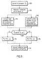
- FIG. 3 is a flowchart representing the steps implemented by the installation to provide this refrigerant flow rate estimate for a displacement compressor variable.
- step 100 the installation supplies the electronic card with the value of the origin pressure P 1 at point B1.
- the air conditioning circuit comprises a first measuring device able to provide a value relative to this origin pressure P 1 .
- the first member may be a temperature sensor that provides the instantaneous value of the air temperature T in the evaporator. This probe can be placed in the fins of the evaporator.
- the first member may be a temperature sensor 22 placed downstream of the evaporator which provides the instantaneous value of the air temperature T air at the inlet of the evaporator.
- the first member is a temperature sensor 122 implanted in the circuit at point B1 capable of supplying the temperature T FL of the refrigerant in the circuit.
- This probe 122 is placed in contact with the liquid part of the refrigerant.
- the origin point B 1 is advantageously placed in an area of the circuit where the fluid is in a two-phase state, which excludes the overheating zone from the evaporator.
- the part of the refrigerant in liquid form is important, which makes this area favorable to a such measure.
- the temperature sensor 122 (and thus the origin point B1) is placed in this fluid injection zone. Indeed, for air conditioning circuits using this type of regulator, the liquid phase of the fluid is quickly vaporized in the evaporator. The probe is placed at the beginning of the trip refrigerant in the evaporator so as to be in the most liquid phase possible.
- the probe used 122 (respectively 22) has a low constant time.
- the value of the temperature supplied by the probe 122 (respectively 22) is transmitted to the electronic card (link 30) which applies the fluid saturation law to deduce the value of the pressure of the fluid P 1 .
- the equation in Appendix A1.1 represents the law of saturation of the fluids connecting the pressure P 1 to the temperature T FL supplied by the probe 22.
- the equation of the appendix A1.2 represents the law of saturation of the fluids connecting the pressure P 1 to the temperature T air supplied by the probe 22.
- the electronic card further receives the value of the temperature of the air blown in downstream of the evaporator T ae , supplied by the cockpit regulator 41 and the efficiency value of the evaporator ⁇ ev to calculate the pressure P 1 .
- the efficiency value corresponds to a heat exchange efficiency. This value applies here only to the area of the evaporator where the probe is used.
- the electronic board receives the value measured by the probe 122 (respectively 22) by the link 30 and calculates the value of the origin pressure P 1 according to the equation of Appendix A1.1 (respectively A 1.2).
- the origin pressure P 1 can be measured directly by a sensor 222 placed at the point B1, for example at the inlet of the evaporator 13. This measurement is transmitted to the electronic card 401 via the link 30.
- the air conditioning circuit comprises a second measuring member able to provide a value relating to the suction pressure P 2 .
- the compressor of the air conditioning circuit is a variable displacement compressor provided with a control valve.
- the suction pressure P 2 of a variable displacement compressor is related to the intensity value Iv of the compressor control valve. Thus from the value of this intensity, it is possible to estimate the pressure P 2 at point B2.
- the second measuring device is able to determine the instantaneous value of the intensity I v of the compressor control valve and to transmit this value to the electronic card.
- the electronic card 401 estimates the value of the arrival pressure P 2 from the value of the intensity I v thus obtained.
- FIG. 4 represents an example of a curve connecting the suction pressure P 2 of a compressor to the intensity I v .
- This curve has been established for an externally controlled compressor.
- the equation corresponding to Part I of the curve is provided in Appendix A2.
- the suction pressure P 2 changes according to Iv (part I of the curve).
- the suction pressure of the compressor P 2 reaches the constant value P 2_min .
- the equation in Appendix A2 is no longer valid.
- the estimation of the suction pressure of the compressor P 2 from the measurement of the intensity Iv of the control valve can therefore be performed by determining whether the compressor is in maximum displacement, ie by determining whether the instantaneous value of the suction pressure of the fluid P 2 is less than or equal to P 2_min .
- the electronic card makes an initial estimate P 2_init of the suction pressure of the compressor from the intensity I v of the control valve and determines if the compressor is in maximum capacity. If necessary, the electronic card 401 adjusts the initial estimate of the suction pressure P 2_init of the compressor, which provides the final estimate P 2 of this pressure.
- the estimation of the suction pressure P 2 is carried out by the steps 102, 104, 106, 108, 110, and 112, according to this embodiment.
- step 102 the instantaneous value of the intensity I v of the control valve is measured by the second measuring member.
- This measuring device is a sensor that can be linked to any computer of the vehicle.
- step 104 the electronic card uses the equation linking the pressure P 2 to the intensity I v of the control valve, for example the equation in Appendix A2.1, to calculate an initial estimate of the suction pressure P 2_init of the compressor from the measured value of the intensity I v .
- the electronic card uses the equation of Annex A3 linking the flow rate of fluid in the air conditioning circuit at a pressure difference between points B1 and B2 to determine if the compressor is in maximum displacement.
- step 106 the electronic card calculates an estimate of the suction pressure when the compressor is in maximum capacity P 2_min from the equation of Appendix A3.
- the equation in Annex A3 provides the flow rate of refrigerant m as a function of the pressure origin P 1 and the suction pressure P 2 .
- the refrigerant flow rate m is related to the displacement of the compressor C y , to the high pressure P d , to the suction pressure P 2 and to the speed of rotation of the compressor N, according to the equation of the Annex A5.
- the identification of the equation of Annex A3 to the equation of Annex A5 provides the equation of Annex A6 which relates the suction pressure P 2 to the high pressure P d , to the pressure origin P 1 , at the speed of rotation of the compressor N and the cylinder capacity of the compressor C y .
- the value of the displacement C y of the compressor is known.
- the electronic card can thus calculate the suction pressure P 2_min of the fluid for a compressor in maximum capacity according to this equation.
- the value of the rotation speed N of the compressor is supplied to the card by the injection computer 42 via the link 33.
- the installation may comprise a pressure sensor 25 or a temperature sensor 125 to estimate the high pressure P d . In general, such sensors are present on the air conditioning circuits.
- the origin pressure P 1 was estimated at step 100.
- step 108 the electronic card compares the initial estimate P 2_init of the suction pressure of the compressor P 2 , obtained in step 104, with the value of the suction pressure of the compressor in maximum capacity P 2_min obtained in step 106 and provides in step 110 or 112 a final estimate of the suction pressure P 2 as a function of the result of the comparison.
- the value of the suction pressure P 2 corresponds to the initial estimate P 2_init of the suction pressure of the compressor obtained in step 104.
- the suction pressure P 2 is estimated according to the equation of the appendix.
- the electronic card can solve the equation of Annex A6 to provide the value of the suction pressure P 2 , the value of the speed of N rotation of the compressor provided by the injection computer 42, and the value of the high pressure P d provided by the sensor 25 (respectively 125).
- the second measuring member may be a pressure sensor 23, placed at the point B2, able to provide a measurement of the instantaneous value of the suction pressure P 2 of the compressor. This measurement is transmitted to the electronic card 401, via the link 30.
- step 114 the electronic card implements the equation of Appendix A3 and uses the estimated values of the origin pressure P 1 and the suction pressure P 2 to calculate a quantity relative to the refrigerant.
- the electronic card 401 solves the equation of Appendix A3 to calculate an estimate of the flow rate of refrigerant m in the air conditioning circuit.
- the pressure drop (P 1 -P 2 ) is calculated from the values of the pressures P 1 and P 2 estimated during the previous steps.
- S is a constant relative to the air conditioning circuit.
- the coefficient ⁇ corresponds to the charge density of the fluid used, for example that of the fluid R134a.
- the coefficient K is obtained as a function of the choice of calculation of the charge density ⁇ .
- This load density ⁇ can be calculated from the origin pressure P 1 , according to the equation in Appendix A4.1, or from the suction pressure P 2 , according to the equation in Appendix A4 .2, or from an average of these two pressures.
- Appendix A4.3 contains an example equation providing the charge density p for the subcritical R 134a refrigerant.
- the invention is not limited to an air conditioning circuit operating with a subcritical refrigerant.
- Appendix A4.4 is an example of an equation providing the charge density p for the super-critical CO2 refrigerant (R744).
- the estimation of the flow rate of refrigerant m is particularly useful in the air conditioning circuits. It allows in particular to calculate an estimate of the power absorbed by the compressor P a .
- the power P absorbed by the compressor may be estimated from the mass effect of refrigerant flow m obtained according to the first embodiment, for example according to the equation provided by the Annex A7.
- the electronic card 401 solves this equation from the value of the flow rate of refrigerant m estimated according to the invention, the value of the speed of rotation of the compressor N supplied by the injection computer 42, the value of the pressure suction P 2 previously estimated and the value of the high pressure P d provided by the sensor 25 (respectively 125).
- the constants C and D are related to operating parameters of the air conditioning circuit and therefore fixed as calculation parameters.
- the computer then sends the engine injection module the estimated value of the mechanical power absorbed by the compressor P a and adapts the nominal power absorbed by the compressor, if it exceeds a maximum value defined by the computer from this point of view. estimated value. As a result, the fuel consumption is reduced and the excessive increases in the power absorbed by the compressor are better controlled.
- Figure 4 illustrates the accuracy of the estimation of the refrigerant flow rate m according to this embodiment for the subcritical refrigerant R134a.
- the figure is a diagram representing the value of the flow of refrigerant m (ordinates) as a function of the value of the difference of [ ⁇ * (P 1 - P 2 )] (abscissa).
- the origin point B1 is located at the outlet of the evaporator.
- the square-shaped points are obtained for a measured suction pressure P 2 and an origin pressure P 1 estimated from the air temperature measurement probe.
- the diamond-shaped points are obtained for a pressure P 1 and a pressure P 2 measured.
- the installation according to the invention is used to obtain an estimate of the suction pressure P 2 of the refrigerant.
- the electronic card 401 implements the resolution of the equation of Appendix A3 to calculate an estimate of the suction pressure P 2 of the refrigerant, when the vehicle is already equipped with a known device for estimating the flow of refrigerant.
- a known device for estimating the flow of refrigerant is described in French Patent Application No. 01 16568.
- the cooling member is a condenser, which allows the use of a subcritical refrigerant, such as the refrigerant R134.
- This device comprises measuring devices for establishing values relating to the temperature of the outside air flow at the inlet of the condenser T aek and the pressure P d of the refrigerant at the outlet of the compressor.
- the electronic card then implements the equation of Appendix A1 to calculate an estimate of the flow rate of refrigerant m in the air conditioning circuit from the values of the temperature of the outside air flow blown at the inlet of the condenser T ack , and the pressure of the refrigerant at the outlet of the compressor P d .
- the value of the origin pressure P 1 is provided by step 100.
- the charge density of the fluid ⁇ can be estimated from P 1 according to Appendix A4.1.
- the device of patent JP 2001-73941 can operate with an air conditioning circuit in which the cooling member is an external cooler ("gas cooler") and the fluid Refrigerant is the supercritical fluid CO2 (R744).
- the cooling member is an external cooler ("gas cooler")
- the fluid Refrigerant is the supercritical fluid CO2 (R744).
- This estimate P 2 can be used to calculate the power consumed by the compressor and also ensure its proper operation. It can also be used to control or validate a value of the suction pressure obtained by other means, such as that obtained for example by using the intensity of the current of the compressor valve according to steps 102 and 104.
- the electronic card 401 solves the equation in Annex A3 to detect the maximum displacement of a compressor at variable displacement.
- the first embodiment of the invention uses this detection the maximum displacement, but the detection of the displacement of the compressor may be used in other applications. For example, in the context of a regulation / control of the cold loop, this detection is used to stop the control of the compressor and thus optimize the regulation of the supply air temperature.
- This form of embodiment has been described with reference to steps 102, 104, 106, 108, 110 and 112 of FIG. 3.
- the present invention also aims at the software code that it involves, while especially when it is made available on any support readable on a computer.
- computer-readable medium covers a storage medium, for example magnetic or optical, as well as a transmission means, such as a signal digital or analog.
Abstract
Description
L'invention concerne les circuits de climatisation des véhicules à moteur.The invention relates to air conditioning circuits of motor vehicles.
Une telle installation est divulguée par exemple par le document FR 2 711 731.Such an installation is disclosed for example by the document FR 2 711 731.
Dans les véhicules à moteur classiques, le compresseur du circuit de climatisation est entraíné par le moteur et consomme donc une partie de la puissance du moteur. Bien que la puissance absorbée par le compresseur, quand il est en marche, ne soit pas importante, elle influe cependant sur le rendement du moteur. En effet, la puissance réellement absorbée par le compresseur diminue le rendement du moteur, augmentant ainsi la consommation de carburant et la pollution générée par les gaz d'échappement du véhicule.In conventional motor vehicles, the air conditioning system compressor is driven by the engine and therefore consumes some of the power of the engine. Although the power absorbed by the compressor, when it is running, is not important, however, it influences engine performance. Indeed, the power actually absorbed by the compressor decreases the efficiency of the engine, thus increasing the fuel consumption and pollution generated by vehicle exhaust.
Pour optimiser le rendement du moteur, une solution consiste à estimer la puissance instantanée réellement absorbée par le compresseur. La connaissance de cette information permet, en effet, d'adapter les paramètres d'injection du moteur aux besoins réels. En l'absence de cette information, le calculateur d'injection choisit, par défaut, des paramètres d'injection correspondant à la valeur maximale de la puissance absorbée, valeur qui est rarement atteinte en pratique.To optimize the efficiency of the motor, one solution is to estimate the power instantaneous actually absorbed by the compressor. Knowledge of this information allows, in fact, to adapt the engine injection parameters to real needs. In the absence of this information, the injection computer chooses, by default, parameters injection value corresponding to the maximum value of the power input, which is rarely achieved in practice.
Cet inconvénient peut concerner les compresseurs mécaniques à contrôle interne qui fonctionnent par l'intermédiaire de l'embrayage interposé entre le moteur et le compresseur. En mode régulé, les compresseurs à contrôle interne adaptent leur cylindrée suivant une loi linéaire reliant la valeur de la pression en entrée du compresseur, dite basse pression à la valeur de sortie du compresseur, dite haute pression. Pourtant, il arrive que la puissance réellement absorbée par le compresseur soit inférieure à sa puissance nominale.This disadvantage may concern the internal control mechanical compressors which operate through the clutch interposed between the engine and the compressor. In regulated mode, the internal control compressors adapt their cubic capacity according to a linear law connecting the value of the pressure at the input of the compressor, so-called low pressure at the output value of the compressor, called high pressure. Yet, it happens that the power actually absorbed by the compressor is less than its power nominal.
De tels compresseurs absorbent une puissance qui dépend des conditions de fonctionnement et qui ne peut donc être réduite, même si on connaít la puissance réellement absorbée par le compresseur. En revanche, il est possible de réguler le fonctionnement de la climatisation en débrayant le compresseur lorsque la puissance n'est pas acceptable. Such compressors absorb a power that depends on the operating conditions and that can not be reduced, even if we know the power actually absorbed by the compressor. On the other hand, it is possible to regulate the operation of the air conditioning by disengaging the compressor when the power is not acceptable.
Cet inconvénient est encore plus gênant pour les compresseurs à contrôle externe, dont l'utilisation se généralise.This disadvantage is even more troublesome for compressors with external control, which the use becomes widespread.
En effet, dans les compresseurs mécaniques à contrôle externe, la puissance réellement absorbée par le compresseur est souvent inférieure à sa puissance nominale. Par suite, l'injection du moteur doit compenser l'écart entre la puissance mécanique nominale et la puissance mécanique réellement absorbée, ce qui diminue le rendement du moteur.Indeed, in mechanical compressors with external control, the power actually absorbed by the compressor is often less than its rated power. As a result, the engine injection must compensate for the difference between the nominal mechanical power and the mechanical power actually absorbed, which decreases engine efficiency.
Dans des réalisations connues, l'estimation de la puissance instantanée absorbée par le compresseur est obtenue à partir d'une cartographie des états de fonctionnement les plus usités. Cette cartographie comporte des états de référence, chaque état de référence étant associé à une valeur de la puissance absorbée par le compresseur, fournie par des essais préalables. L'estimation de la puissance absorbée par le compresseur est obtenue en comparant l'état de fonctionnement du circuit de climatisation à un état de référence faisant partie de la cartographie. Les méthodes basées sur une telle cartographie requièrent des temps de développement importants et se fondent sur des données empiriques. Elles présentent l'inconvénient de ne pas prendre en compte tous les cas possibles de fonctionnement et par suite de fournir des résultats approximatifs.In known embodiments, the estimate of the instantaneous power absorbed by the compressor is obtained from a map of the most USIT. This map includes reference states, each reference state being associated with a value of the power absorbed by the compressor, provided by tests prerequisites. The estimate of the power absorbed by the compressor is obtained by comparing the operating state of the air conditioning circuit to a reference state making part of the cartography. Methods based on such mapping require development time and are based on empirical evidence. They have the disadvantage of not taking into account all the possible cases of operation and as a result to provide approximate results.
Dans d'autres réalisations, la puissance instantanée absorbée par le compresseur est calculée à partir d'une estimation du débit de fluide frigorigène. La demande de brevet français n°01 16568 propose une estimation du débit de fluide frigorigène dans le circuit de climatisation à partir d'une information relative à la vitesse du véhicule et d'une information relative à la tension du groupe moto-ventilateur. Cependant, ces deux informations ne sont pas disponibles sur tous les véhicules.In other embodiments, the instantaneous power absorbed by the compressor is calculated from an estimate of the refrigerant flow rate. The patent application French No. 01 16568 proposes an estimation of the flow of refrigerant in the circuit of air conditioning from information relating to the speed of the vehicle and a information relating to the voltage of the motor-fan unit. However, these two information is not available on all vehicles.
C'est un but de l'invention de proposer une installation de climatisation permettant la mise en oeuvre d'une équation liant le débit de fluide frigorigène à des paramètres relatifs au fluide frigorigène et disponibles sur tout véhicule pour fournir une estimation du débit de fluide frigorigène, notamment pour calculer la puissance absorbée par le compresseur.It is an object of the invention to provide an air-conditioning installation which allows the of an equation linking the flow rate of refrigerant to parameters relating to the refrigerant and available on any vehicle to provide an estimate of the flow rate of refrigerant, in particular to calculate the power absorbed by the compressor.
Plus généralement, c' est un but de l'invention de proposer une installation de climatisation permettant la mise en oeuvre d'une telle équation pour fournir une estimation d'une grandeur relative au fluide frigorigène.More generally, it is an object of the invention to provide an air conditioning installation. allowing the implementation of such an equation to provide an estimate of a relative size of the refrigerant.
L'invention propose à cet effet une installation de climatisation pour véhicule à moteur munie d'un calculateur d'injection et d'un circuit de fluide frigorigène comprenant un compresseur, un organe de refroidissement, un organe de détente et un évaporateur. L'installation comprend également un dispositif électronique de contrôle destiné à interagir avec le circuit de fluide frigorigène et le calculateur d'injection. Avantageusement, l'installation comprend :
- un premier organe de mesure propre à fournir une valeur relative à la pression du fluide en un premier point du circuit de climatisation, dite première pression, ledit premier point étant situé entre la sortie de l'organe de détente et la sortie de l'évaporateur,
- un deuxième organe de mesure propre à fournir une valeur relative à la pression du fluide en un deuxième point du circuit de climatisation, dite deuxième pression, le deuxième point étant situé à l'entrée du compresseur,
- a first measuring device adapted to supply a value relating to the pressure of the fluid at a first point of the air conditioning circuit, said first pressure, said first point being located between the outlet of the expansion member and the outlet of the evaporator ,
- a second measuring device adapted to supply a value relating to the pressure of the fluid at a second point of the air conditioning circuit, called the second pressure, the second point being situated at the inlet of the compressor,
Selon une première forme de réalisation de l'invention, la grandeur relative au fluide frigorigène est le débit massique de fluide frigorigène tandis que le dispositif électronique de contrôle est apte à résoudre ladite équation à partir de la valeur de la première pression et de la valeur de la deuxième pression.According to a first embodiment of the invention, the quantity relative to the fluid refrigerant is the mass flow of refrigerant while the electronic device of control is able to solve said equation from the value of the first pressure and the value of the second pressure.
Selon une deuxième forme de réalisation de l'invention, la grandeur relative au fluide frigorigène est la deuxième pression et le dispositif électronique de contrôle est apte à résoudre ladite équation à partir de la valeur du débit massique du fluide et de la valeur de la première pression.According to a second embodiment of the invention, the quantity relative to the fluid refrigerant is the second pressure and the electronic control device is able to solve the equation from the value of the mass flow of the fluid and the value of the first pressure.
Selon cette deuxième forme de réalisation de l'invention, l'organe de refroidissement est un condenseur et l'installation comporte des organes de mesures propres à fournir une valeur relative à la température du flux d'air extérieur à l'entrée du condenseur et une valeur relative à la pression du fluide en sortie du compresseur, dite haute pression, tandis que le dispositif électronique de contrôle est apte à utiliser les valeurs fournies par lesdits organes de mesure pour mettre en oeuvre la résolution d'une équation, liant le débit massique du fluide frigorigène à la température du flux d'air extérieur à l'entrée du condenseur et à la haute pression pour calculer une estimation de la valeur instantanée du débit massique du fluide frigorigène.According to this second embodiment of the invention, the cooling member is a condenser and the installation includes measuring devices capable of providing a value relative to the temperature of the outside air flow at the condenser inlet and a value relative to the pressure of the fluid at the outlet of the compressor, said high pressure, while that the electronic control device is able to use the values provided by the measuring devices to implement the resolution of an equation, binding the flow mass of the refrigerant at the temperature of the outside air flow at the inlet of the condenser and at high pressure to calculate an estimate of the instantaneous value of the mass flow rate of the refrigerant.
Selon une troisième forme de réalisation de l'invention, le compresseur est à cylindrée variable et la grandeur relative au fluide frigorigène est la valeur minimale de la pression du fluide correspondant à la cylindrée maximale du compresseur, le dispositif électronique de contrôle étant apte à résoudre ladite équation à partir de la valeur de la première pression et de la valeur de la vitesse de rotation du compresseur.According to a third embodiment of the invention, the compressor is at capacity variable and the magnitude relative to the refrigerant is the minimum value of the pressure of the fluid corresponding to the maximum displacement of the compressor, the electronic device control being able to solve said equation from the value of the first pressure and the value of the rotational speed of the compressor.
La valeur de la vitesse de rotation du compresseur peut être fournie au dispositif électronique de contrôle par le calculateur d'injection.The value of the rotational speed of the compressor can be supplied to the device electronic control by the injection computer.
Dans un mode particulier de réalisation, l'installation comporte un compresseur muni d'une vanne de contrôle et le deuxième organe de mesure est un capteur propre à fournir la valeur instantanée de l'intensité de la vanne de contrôle, le dispositif électronique de contrôle étant apte à calculer une estimation initiale de la deuxième pression à partir de la valeur de l'intensité de la vanne de contrôle du compresseur fournie par le deuxième organe de mesure.In a particular embodiment, the installation comprises a compressor provided with a control valve and the second measuring device is a sensor clean to provide the value the intensity of the control valve, the electronic control device being able to calculate an initial estimate of the second pressure from the value of the intensity of the compressor control valve supplied by the second measured.
Selon ce mode de réalisation, le dispositif électronique de contrôle est apte à comparer l'estimation initiale de la deuxième pression à la valeur minimale de la deuxième pression.According to this embodiment, the electronic control device is able to compare the initial estimate of the second pressure to the minimum value of the second pressure.
Le dispositif électronique de contrôle est alors apte à réagir au fait que l'estimation initiale de la deuxième pression est inférieure ou égale à la valeur minimale de la deuxième pression en fournissant une estimation finale de la deuxième pression sensiblement égale à la valeur minimale de la deuxième pression.The electronic control device is then able to react to the fact that the initial estimate the second pressure is less than or equal to the minimum value of the second pressure by providing a final estimate of the second substantially equal pressure at the minimum value of the second pressure.
Le dispositif électronique de contrôle est également apte à réagir au fait que la deuxième pression est supérieure à la valeur minimale de la deuxième pression en fournissant une estimation finale de la deuxième pression sensiblement égale à l'estimation initiale de la deuxième pression.The electronic control device is also able to react to the fact that the second pressure is greater than the minimum value of the second pressure by providing a final estimate of the second pressure substantially equal to the initial estimate of the second pressure.
Dans une autre mode de réalisation, le deuxième organe est un capteur placé au niveau du deuxième point, propre à fournir directement la valeur instantanée de la deuxième pression.In another embodiment, the second member is a sensor placed at the level of second point, able to directly provide the instantaneous value of the second pressure.
Selon une autre caractéristique de l'invention, le premier organe de mesure est un capteur placé au niveau du premier point, propre à fournir la valeur instantanée de la première pression.According to another characteristic of the invention, the first measuring member is a sensor placed at the level of the first point, able to provide the instantaneous value of the first pressure.
Dans une première variante, le premier organe de mesure peut être une sonde de température, placée dans les ailettes de l'évaporateur, propre à fournir une mesure de la valeur instantanée de la température de l'air dans l'évaporateur.In a first variant, the first measuring member may be a probe of temperature, placed in the fins of the evaporator, suitable for providing a measure of the instantaneous value of the air temperature in the evaporator.
Dans une deuxième variante, le premier organe de mesure peut être une sonde de température, placée en aval de l'évaporateur, propre à fournir une mesure de la valeur instantanée de la température de l'air entrant dans l'évaporateur.In a second variant, the first measuring device may be a temperature probe, placed downstream of the evaporator, capable of providing a measure of the instantaneous value the temperature of the air entering the evaporator.
Dans une troisième variante, le premier organe de mesure peut être une sonde de température propre à fournir la valeur instantanée de la température du fluide, la sonde étant placée au niveau du premier point, au contact de la partie liquide du fluide.In a third variant, the first measuring device may be a probe of temperature to provide the instantaneous value of the fluid temperature, the probe being placed at the first point, in contact with the liquid part of the fluid.
Selon cette troisième variante, le premier point est situé à un endroit du circuit de climatisation où le fluide frigorigène est dans un état diphasique.According to this third variant, the first point is located at a location of the air conditioning circuit where the refrigerant is in a two-phase state.
En particulier, selon la première variante et la troisième variante, l'organe de détente peut être un détendeur thermostatique tandis que la sonde de température est placée dans la zone d'injection de fluide de l'évaporateur.In particular, according to the first variant and the third variant, the detent may be a thermostatic expansion valve while the temperature sensor is placed in the zone fluid injection of the evaporator.
Selon ces trois variantes, le dispositif électronique de contrôle est propre à estimer la valeur de la première pression à partir de la valeur fournie par la sonde de température.According to these three variants, the electronic control device is able to estimate the value the first pressure from the value provided by the temperature sensor.
En complément, la sonde de température a une constante de temps inférieure ou égale à 5 secondes. In addition, the temperature probe has a time constant less than or equal to 5 seconds.
D'autres caractéristiques et avantages de l'invention apparaítront à l'examen de la description détaillée ci-après, et des dessins annexés sur lesquels:
- la figure 1a représente une vue d'ensemble d'un dispositif de climatisation installé à bord d'un véhicule,
- la figure 1b est un schéma d'un circuit de climatisation pour un fluide frigorigène super-critique,
- la figure 2 est un schéma d'une installation de véhicule automobile à moteur, munie du dispositif de contrôle selon l'invention,
- la figure 3 est un organigramme illustrant les différentes étapes mises en oeuvre par une installation munie d'un compresseur à cylindrée variable, selon l'invention,
- la figure 4 est un diagramme illustrant la courbe de régulation d'un compresseur à contrôle externe, et
- la figure 5 illustre la précision de l'estimation selon l'invention.
- FIG. 1a represents an overall view of an air conditioning device installed on board a vehicle,
- FIG. 1b is a diagram of an air conditioning circuit for a supercritical refrigerant,
- FIG. 2 is a diagram of a motor vehicle engine installation equipped with the control device according to the invention,
- FIG. 3 is a flowchart illustrating the various steps implemented by an installation equipped with a variable displacement compressor, according to the invention,
- FIG. 4 is a diagram illustrating the control curve of a compressor with external control, and
- FIG. 5 illustrates the accuracy of the estimation according to the invention.
L'annexe A comporte les équations mathématiques principales utilisées dans l'installation.Appendix A contains the main mathematical equations used in the installation.
Les dessins contiennent, pour l'essentiel, des éléments de caractère certain. Ils pourront donc non seulement servir à mieux faire comprendre la description, mais aussi contribuer à la définition de l'invention, le cas échéant.The drawings contain, for the most part, elements of a certain character. They could so not only to make the description better understood, but also to contribute to the definition of the invention, where appropriate.
On se réfère tout d'abord à la figure 1a qui représente une vue d'ensemble d'un appareil de climatisation intégré à un véhicule. L'appareil de climatisation comprend un circuit fermé de fluide frigorigène. L'appareil de climatisation comprend également un compresseur 14, un organe de refroidissement 11, un organe de détente 12 et un évaporateur 13, parcourus dans cet ordre par le fluide frigorigène. Le circuit peut également comporter un accumulateur 17 placé entre la sortie de l'évaporateur et l'entrée du compresseur pour éviter les coups de liquide.Reference is first made to FIG. 1a, which is an overview of an apparatus for air conditioning built into a vehicle. The air conditioning unit has a closed circuit of refrigerant. The air conditioning unit also comprises a compressor 14, a cooling member 11, an expansion member 12 and an evaporator 13, traveled in this order by the refrigerant. The circuit may also include an accumulator 17 between the evaporator outlet and the compressor inlet to prevent shots of liquid.
L'organe de refroidissement 11 reçoit un flux d'air extérieur 16 pour évacuer la chaleur prélevée dans l'habitacle par l'évaporateur, qui dans certaines conditions de fonctionnement est mis en mouvement par un groupe moto-ventilateur 15.The cooling member 11 receives an outside air flow 16 to evacuate the heat taken from the passenger compartment by the evaporator, which under certain operating conditions is set in motion by a motor-fan unit 15.
L'évaporateur 13 reçoit un flux d'air d'un pulseur 20 alimenté par un flux d'air extérieur 18 et produit un flux d'air climatisé 21 qui est envoyé vers l'habitacle du véhicule.The evaporator 13 receives a flow of air from a blower 20 fed by an outside air flow 18 and produces a flow of conditioned air 21 which is sent to the passenger compartment of the vehicle.
Dans l'exemple de la figure 1a, le circuit de climatisation est parcouru par un fluide frigorigène sous-critique, par exemple le fluide frigorigène R134a. Un tel fluide a une pression critique supérieure à la pression de la source chaude. Dans les circuits de climatisation utilisant de tels fluides, comme celui représenté sur la figure 1, l'organe de refroidissement 11 est un condenseur. L'organe de détente peut être par exemple un orifice calibré ou un détendeur thermostatique.In the example of Figure 1a, the air conditioning circuit is traversed by a fluid subcritical refrigerant, for example R134a refrigerant. Such a fluid has a critical pressure greater than the pressure of the hot source. In the circuits of air conditioning using such fluids, such as that shown in Figure 1, the organ of cooling 11 is a condenser. The detent member may for example be an orifice calibrated or a thermostatic expansion valve.
Toutefois, l'invention n'est pas limitée à des circuits de climatisation fonctionnant avec des fluides frigorigènes sous-critiques et munis d'un organe de refroidissement du type condenseur.However, the invention is not limited to air conditioning circuits operating with subcritical refrigerants and equipped with a cooling device of the type condenser.
En particulier, le circuit de climatisation peut-être parcouru par un fluide frigorigène supercritique, tel que le fluide frigorigène CO2. Pour les fluides supercritiques, la haute pression à forte température est supérieure à la pression critique du fluide. La figure 1b représente un circuit de climatisation fonctionnant avec le fluide supercritique CO2. Dans un tel circuit, l'organe de refroidissement 11 est un refroidisseur externe ("gas cooler"). L'organe de détente 12 peut être par exemple une vanne électrique ou une vanne mécanique. Le circuit comporte un évaporateur 13, un accumulateur 17 et un compresseur 14 fonctionnant tel que décrit ci-avant. Le circuit comporte en outre un échangeur thermique interne 9.In particular, the air conditioning circuit may be traversed by a refrigerant supercritical, such as CO2 refrigerant. For supercritical fluids, the high High temperature pressure is greater than the critical pressure of the fluid. Figure 1b represents an air conditioning circuit operating with the supercritical fluid CO2. In such a circuit, the cooling member 11 is an external cooler ("gas cooler"). The expansion member 12 may for example be an electric valve or a mechanical valve. The circuit comprises an evaporator 13, an accumulator 17 and a compressor 14 operating as described above. The circuit further comprises a heat exchanger internal 9.
Dans les circuits de climatisation utilisant un fluide supercritique, le refroidissement du fluide après compression n'entraíne pas de changement de phase. Le fluide ne passe à l'état liquide qu'au cours de la détente. L'échangeur thermique interne 9 permet de refroidir très fortement, voire de liquéfier le fluide sortant du refroidisseur externe 11.In air conditioning circuits using a supercritical fluid, the cooling of the fluid after compression does not cause phase change. The fluid does not go to the state liquid only during the relaxation. The internal heat exchanger 9 makes it possible to cool very strongly, or even to liquefy the fluid leaving the external cooler 11.
Dans la suite, la description sera faite en référence au circuit de climatisation de la figure 1 fonctionnant avec un fluide sous-critique tel que le R134a, à titre d'exemple non limitatif.In the following, the description will be made with reference to the air conditioning circuit of FIG. 1 operating with a subcritical fluid such as R134a, by way of non-limiting example.
La figure 2 est un schéma représentant l'installation selon l'invention mise en place dans un véhicule automobile. Le véhicule automobile est animé par un moteur 43, commandé par un calculateur d'injection 42. Le calculateur reçoit des informations de divers capteurs qu'il interprète pour ajuster les paramètres.FIG. 2 is a diagram showing the installation according to the invention set up in a motor vehicle. The motor vehicle is driven by a motor 43, ordered by an injection computer 42. The computer receives information from various sensors that he interprets to adjust the parameters.
Le calculateur d'injection 42 est propre à fournir des informations sur les conditions intérieures ou extérieures du véhicule (informations fournies par un capteur solaire, nombre d'occupants, etc.). En particulier, il fournit des informations 33 sur des valeurs instantanées relatives au fonctionnement du véhicule, et notamment sur la vitesse de rotation du compresseur N.The injection computer 42 is able to provide information on the conditions inside or outside the vehicle (information provided by a solar collector, number occupants, etc.). In particular, it provides information 33 on instantaneous values relating to the operation of the vehicle, and in particular the speed of rotation of the compressor N.
Le véhicule est également équipé de l'appareil de climatisation 10 décrit ci-dessus, représentée schématiquement sur la figure 2. De plus, l'installation est munie d'un calculateur de climatisation 40, comprenant un régulateur d'habitacle 41 et un régulateur de boucle de climatisation 402. Le régulateur d'habitacle 41 est destiné à fixer la consigne de température Tac de l'air extérieur soufflé à l'entrée de l'évaporateur 11.The vehicle is also equipped with the air conditioning unit 10 described above, shown schematically in FIG. 2. In addition, the installation is provided with an air conditioning computer 40, comprising a cockpit regulator 41 and a regulator 402. The cabin controller 41 is intended to set the temperature setpoint T ac of the outside air blown at the inlet of the evaporator 11.
Le calculateur d'injection du moteur 42 peut agir sur l'appareil de climatisation grâce au régulateur de boucle de climatisation 402 pour commander la mise en marche ou l'arrêt de l'appareil de climatisation selon des conditions liées au fonctionnement du moteur ou des commandes externes. Par exemple, le calculateur d'injection 42 peut interdire la mise en marche de l'appareil de la climatisation lorsque le moteur est fortement sollicité.The engine injection calculator 42 can act on the air conditioning unit thanks to the air conditioning loop controller 402 for controlling the start or stop of the air-conditioning unit under conditions related to the operation of the engine or external commands. For example, the injection computer 42 may prohibit the implementation of operation of the air conditioning unit when the motor is under heavy load.
La Demanderesse propose d'optimiser le fonctionnement du circuit de climatisation d'une telle installation, en mettant en oeuvre une équation liant le débit de fluide dans le circuit de climatisation à une différence de pression entre deux points situés sur la ligne basse pression. En référence à la figure 2, la ligne basse pression correspond à la partie du circuit de climatisation qui se trouve entre la sortie du détendeur 12 et l'entrée du compresseur 14.The Applicant proposes to optimize the operation of the air conditioning circuit of a such an installation, by implementing an equation linking the flow of fluid in the circuit of air conditioning at a pressure difference between two points on the low line pressure. With reference to FIG. 2, the low pressure line corresponds to the part of the circuit air conditioning which is located between the outlet of the regulator 12 and the inlet of the compressor 14.
Pour cela, le régulateur de l'habitacle 41, le calculateur d'injection du moteur 42 et l'appareil de climatisation 10 sont reliés à un dispositif électronique de contrôle, par exemple une carte électronique 401 pour un échange d'informations.For this, the cockpit regulator 41, the engine injection computer 42 and the air-conditioning unit 10 are connected to an electronic control device, for example example an electronic card 401 for an exchange of information.
La carte électronique 401 est programmée pour résoudre les équations permettant d'estimer la différence de pression sur la ligne basse pression à partir de mesures fournies par l'installation et pour résoudre l'équation qui lie cette différence de pression au débit de fluide frigorigène. En outre, elle peut-être programmée pour mettre en oeuvre la résolution d'une équation liant la puissance absorbée par le compresseur au débit de fluide frigorigène pour fournir une estimation de la puissance absorbée par le compresseur. Elle est agencée pour transmettre les informations qui résultent de ces estimations au calculateur d'injection 42, via la liaison 32.The electronic card 401 is programmed to solve the equations allowing to estimate the pressure difference on the low pressure line from measurements provided by installation and to solve the equation that links this pressure difference to the flow of Refrigerant. In addition, it may be programmed to implement the resolution an equation linking the power absorbed by the compressor to the flow of refrigerant to provide an estimate of the power absorbed by the compressor. She is arranged to transmit the information that results from these estimates to the injection computer 42, via the link 32.
La carte électronique 401 peut-être considérée comme partie intégrante du calculateur de climatisation 40 du véhicule.The electronic card 401 can be regarded as an integral part of the calculator of air conditioning 40 of the vehicle.
Elle est en liaison avec le régulateur de boucle de climatisation 402 qui a notamment le rôle d'adapter la quantité de chaleur prélevée dans l'habitacle, dite puissance frigorifique, pour atteindre la consigne de température d'air soufflé à la sortie de l'évaporateur ou la consigne de la sonde de l'habitacle.It is in connection with the air conditioning loop controller 402 which has the particular role to adapt the amount of heat taken from the passenger compartment, called cooling capacity, to reach the air temperature setpoint at the evaporator outlet or the setpoint of the cockpit sensor.
Selon une caractéristique de l'invention, la carte électronique 401 peut recevoir des informations provenant de capteurs mis en place sur l'appareil de climatisation par la liaison 30. De tels capteurs sont mis en place pour déterminer la valeur instantanée de la pression du fluide frigorigène P1 en un premier point B1 situé entre la sortie de l'organe de détente et la sortie de l'évaporateur, et de la pression du fluide frigorigène P2 en un deuxième point B2 situé à l'entrée du compresseur. La première pression P1 sera désignée ci-après par "pression origine" et la deuxième pression P2 par "pression d'aspiration".According to a characteristic of the invention, the electronic card 401 can receive information from sensors placed on the air conditioning apparatus via the link 30. Such sensors are set up to determine the instantaneous value of the fluid pressure. refrigerant P 1 at a first point B1 located between the outlet of the expansion member and the outlet of the evaporator, and the pressure of the refrigerant P 2 at a second point B2 located at the inlet of the compressor. The first pressure P 1 will be designated hereinafter by "origin pressure" and the second pressure P 2 by "suction pressure".
De manière générale, la carte électronique 401 est apte à mettre en oeuvre la relation reliant le débit de fluide frigorigène à la différence de pression entre deux points de la ligne basse pression pour déterminer une grandeur relative au fluide frigorigène.In general, the electronic card 401 is able to implement the connecting relationship the flow of refrigerant at the pressure difference between two points of the low line pressure to determine a magnitude relative to the refrigerant.
Dans une première forme de réalisation selon l'invention, cette grandeur relative au fluide frigorigène est le débit de fluide frigorigène. Cette valeur est particulièrement utile pour estimer la puissance consommée par le circuit de climatisation et pour ajuster cette consommation.In a first embodiment of the invention, this quantity relating to the fluid refrigerant is the flow of refrigerant. This value is particularly useful for estimate the power consumed by the air conditioning circuit and to adjust this consumption.
La figure 3 est un organigramme représentant les étapes mises en oeuvre par l'installation pour fournir cette estimation du débit de fluide frigorigène pour un compresseur à cylindrée variable.FIG. 3 is a flowchart representing the steps implemented by the installation to provide this refrigerant flow rate estimate for a displacement compressor variable.
A l'étape 100, l'installation fournit à la carte électronique la valeur de la pression origine P1 au point B1.In step 100, the installation supplies the electronic card with the value of the origin pressure P 1 at point B1.
Selon un aspect de l'invention, le circuit de climatisation comprend un premier organe de mesure propre à fournir une valeur relative à cette pression origine P1.According to one aspect of the invention, the air conditioning circuit comprises a first measuring device able to provide a value relative to this origin pressure P 1 .
Le premier organe peut être une sonde de température qui fournit la valeur instantanée de la température Tair de l'air dans l'évaporateur. Cette sonde peut-être placée dans les ailettes de l'évaporateur.The first member may be a temperature sensor that provides the instantaneous value of the air temperature T in the evaporator. This probe can be placed in the fins of the evaporator.
En variante, en référence à la figure 2, le premier organe peut être une sonde de température 22 placée en aval de l'évaporateur qui fournit la valeur instantanée de la température Tair de l'air à l'entrée de l'évaporateur.Alternatively, with reference to Figure 2, the first member may be a temperature sensor 22 placed downstream of the evaporator which provides the instantaneous value of the air temperature T air at the inlet of the evaporator.
Dans une autre variante, le premier organe est une sonde de température 122 implantée dans le circuit au point B1 propre à fournir la température TFL du fluide frigorigène dans le circuit. Cette sonde 122 est placée au contact de la partie liquide du fluide frigorigène.In another variant, the first member is a temperature sensor 122 implanted in the circuit at point B1 capable of supplying the temperature T FL of the refrigerant in the circuit. This probe 122 is placed in contact with the liquid part of the refrigerant.
Selon cette variante, le point origine B 1 est avantageusement placé dans une zone du circuit où le fluide se trouve dans un état diphasique, ce qui exclut la zone de surchauffe de l'évaporateur. A l'entrée de l'évaporateur, dans la zone d'injection de fluide, la partie du fluide frigorigène sous forme liquide est importante, ce qui rend cette zone favorable à une telle mesure.According to this variant, the origin point B 1 is advantageously placed in an area of the circuit where the fluid is in a two-phase state, which excludes the overheating zone from the evaporator. At the inlet of the evaporator, in the fluid injection zone, the part of the refrigerant in liquid form is important, which makes this area favorable to a such measure.
Lorsque l'organe de détente est de type détendeur thermostatique, la sonde de température 122 (et donc le point origine B1) est placée dans cette zone d'injection de fluide. En effet, pour les circuits de climatisation utilisant ce type de détendeur, la phase liquide du fluide est rapidement vaporisée dans l'évaporateur. La sonde est donc placée au début du trajet du fluide réfrigérant dans l'évaporateur de manière à se trouver dans la phase la plus liquide possible. When the expansion element is of the thermostatic expansion valve type, the temperature sensor 122 (and thus the origin point B1) is placed in this fluid injection zone. Indeed, for air conditioning circuits using this type of regulator, the liquid phase of the fluid is quickly vaporized in the evaporator. The probe is placed at the beginning of the trip refrigerant in the evaporator so as to be in the most liquid phase possible.
Dans ces variantes de réalisation, la sonde utilisée 122 (respectivement 22) a une faible constante de temps.In these variant embodiments, the probe used 122 (respectively 22) has a low constant time.
La valeur de la température fournie par la sonde 122 (respectivement 22) est transmise à la carte électronique (liaison 30) qui applique la loi de saturation des fluides pour en déduire la valeur de la pression du fluide P1. L'équation de l'annexe A1.1 représente la loi de saturation des fluides reliant la pression P1 à la température TFL fournie par la sonde 22.The value of the temperature supplied by the probe 122 (respectively 22) is transmitted to the electronic card (link 30) which applies the fluid saturation law to deduce the value of the pressure of the fluid P 1 . The equation in Appendix A1.1 represents the law of saturation of the fluids connecting the pressure P 1 to the temperature T FL supplied by the probe 22.
L'équation de l'annexe A1.2 représente la loi de saturation des fluides reliant la pression P1 à la température Tair fournie par la sonde 22. La carte électronique reçoit en outre la valeur de la température de l'air soufflé en aval de l'évaporateur Tae, fournie par le régulateur d'habitacle 41 et la valeur d'efficacité de l'évaporateur ηev pour calculer la pression P1. La valeur d'efficacité correspond à un rendement d'échange thermique. Cette valeur s'applique ici uniquement à la zone de l'évaporateur où la sonde est utilisée.The equation of the appendix A1.2 represents the law of saturation of the fluids connecting the pressure P 1 to the temperature T air supplied by the probe 22. The electronic card further receives the value of the temperature of the air blown in downstream of the evaporator T ae , supplied by the cockpit regulator 41 and the efficiency value of the evaporator η ev to calculate the pressure P 1 . The efficiency value corresponds to a heat exchange efficiency. This value applies here only to the area of the evaporator where the probe is used.
La carte électronique reçoit la valeur mesurée par la sonde 122 (respectivement 22) par la liaison 30 et calcule la valeur de la pression origine P1 conformément à l'équation de l'annexe A1.1 (respectivement A 1.2).The electronic board receives the value measured by the probe 122 (respectively 22) by the link 30 and calculates the value of the origin pressure P 1 according to the equation of Appendix A1.1 (respectively A 1.2).
En variante, la pression origine P1 peut-être mesurée directement par un capteur 222 placé au point B1, par exemple à l'entrée de l'évaporateur 13. Cette mesure est transmise à la carte électronique 401, par la liaison 30.As a variant, the origin pressure P 1 can be measured directly by a sensor 222 placed at the point B1, for example at the inlet of the evaporator 13. This measurement is transmitted to the electronic card 401 via the link 30.
Les étapes suivantes fournissent une estimation de la pression d'aspiration du compresseur P2 au point B2.The following steps provide an estimate of the suction pressure of compressor P 2 at point B2.
Selon une autre caractéristique de l'invention, le circuit de climatisation comprend un deuxième organe de'mesure propre à fournir une valeur relative à la pression d'aspiration P2.According to another characteristic of the invention, the air conditioning circuit comprises a second measuring member able to provide a value relating to the suction pressure P 2 .
Dans une variante de réalisation, le compresseur du circuit de climatisation est un compresseur à cylindrée variable, muni d'une vanne de contrôle. La pression d'aspiration P2 d'un compresseur à cylindrée variable est liée à la valeur de l'intensité Iv de la vanne de contrôle du compresseur. Ainsi à partir de la valeur de cette intensité, il est possible d'estimer la pression P2 au point B2.In an alternative embodiment, the compressor of the air conditioning circuit is a variable displacement compressor provided with a control valve. The suction pressure P 2 of a variable displacement compressor is related to the intensity value Iv of the compressor control valve. Thus from the value of this intensity, it is possible to estimate the pressure P 2 at point B2.
Selon ce mode de réalisation, le deuxième organe de mesure est propre à déterminer la valeur instantanée de l'intensité Iv de la vanne de contrôle du compresseur et à transmettre cette valeur à la carte électronique. La carte électronique 401 estime alors la valeur de la pression d'arrivée P2 à partir de la valeur de l'intensité Iv ainsi obtenue.According to this embodiment, the second measuring device is able to determine the instantaneous value of the intensity I v of the compressor control valve and to transmit this value to the electronic card. The electronic card 401 then estimates the value of the arrival pressure P 2 from the value of the intensity I v thus obtained.
La figure 4 représente un exemple de courbe reliant la pression d'aspiration P2 d'un compresseur à l'intensité Iv. Cette courbe a été établie pour un compresseur à contrôle externe. L'équation correspondant à la partie I de la courbe est fournie dans l'annexe A2. Tant que le compresseur n'a pas atteint sa cylindrée maximale, la pression d'aspiration P2 évolue en fonction de Iv (partie I de la courbe). Cependant, lorsque le compresseur atteint sa cylindrée maximale (partie II de la courbe), la pression d'aspiration du compresseur P2 atteint la valeur constante P2_min. L'équation de l'annexe A2 n'est plus valable.FIG. 4 represents an example of a curve connecting the suction pressure P 2 of a compressor to the intensity I v . This curve has been established for an externally controlled compressor. The equation corresponding to Part I of the curve is provided in Appendix A2. As long as the compressor has not reached its maximum capacity, the suction pressure P 2 changes according to Iv (part I of the curve). However, when the compressor reaches its maximum capacity (part II of the curve), the suction pressure of the compressor P 2 reaches the constant value P 2_min . The equation in Appendix A2 is no longer valid.
L'estimation de la pression d'aspiration du compresseur P2 à partir de la mesure de l'intensité Iv de la vanne de contrôle peut donc être effectuée en déterminant si le compresseur est en cylindrée maximale, c' est à dire en déterminant si la valeur instantanée de la pression d'aspiration du fluide P2 est inférieure ou égale à P2_min.The estimation of the suction pressure of the compressor P 2 from the measurement of the intensity Iv of the control valve can therefore be performed by determining whether the compressor is in maximum displacement, ie by determining whether the instantaneous value of the suction pressure of the fluid P 2 is less than or equal to P 2_min .
Pour cela, la carte électronique effectue une estimation initiale P2_init de la pression d'aspiration du compresseur à partir de l'intensité Iv de la vanne de contrôle et détermine si le compresseur est en cylindrée maximale. Le cas échéant, la carte électronique 401 ajuste l'estimation initiale de la pression d'aspiration P2_init du compresseur, ce qui fournit l'estimation finale P2 de cette pression.For this, the electronic card makes an initial estimate P 2_init of the suction pressure of the compressor from the intensity I v of the control valve and determines if the compressor is in maximum capacity. If necessary, the electronic card 401 adjusts the initial estimate of the suction pressure P 2_init of the compressor, which provides the final estimate P 2 of this pressure.
L'estimation de la pression d'aspiration P2 est réalisée par les étapes 102,104, 106, 108, 110, et 112, selon ce mode de réalisation.The estimation of the suction pressure P 2 is carried out by the steps 102, 104, 106, 108, 110, and 112, according to this embodiment.
A l'étape 102, la valeur instantanée de l'intensité Iv de la vanne de contrôle est mesurée par le deuxième organe de mesure. Cet organe de mesure est un capteur pouvant être lié à tout calculateur du véhicule. In step 102, the instantaneous value of the intensity I v of the control valve is measured by the second measuring member. This measuring device is a sensor that can be linked to any computer of the vehicle.
A l'étape 104, la carte électronique utilise l'équation liant la pression P2 à l'intensité Iv de la vanne de contrôle, par exemple l'équation de l'annexe A2.1, pour calculer une estimation initiale de la pression d'aspiration P2_init du compresseur à partir de la valeur mesurée de l'intensité Iv.In step 104, the electronic card uses the equation linking the pressure P 2 to the intensity I v of the control valve, for example the equation in Appendix A2.1, to calculate an initial estimate of the suction pressure P 2_init of the compressor from the measured value of the intensity I v .
Avantageusement, la carte électronique utilise l'équation de l'annexe A3 liant le débit de fluide dans le circuit de climatisation à une différence de pression entre les points B1 et B2 pour déterminer si le compresseur est en cylindrée maximale.Advantageously, the electronic card uses the equation of Annex A3 linking the flow rate of fluid in the air conditioning circuit at a pressure difference between points B1 and B2 to determine if the compressor is in maximum displacement.
Pour cela, à l'étape 106, la carte électronique calcule une estimation de la pression d'aspiration lorsque le compresseur est en cylindrée maximale P2_min à partir de l'équation de l'annexe A3.For this, in step 106, the electronic card calculates an estimate of the suction pressure when the compressor is in maximum capacity P 2_min from the equation of Appendix A3.
L'équation de l'annexe A3 fournit en effet le débit de fluide frigorigène m en fonction de la pression origine P1 et de la pression d'aspiration P2.The equation in Annex A3 provides the flow rate of refrigerant m as a function of the pressure origin P 1 and the suction pressure P 2 .
Par ailleurs, le débit de fluide frigorigène m est lié à la cylindrée du compresseur Cy, à la haute pression Pd, à la pression d'aspiration P2 et à la vitesse de rotation du compresseur N, selon l'équation de l'annexe A5.Moreover, the refrigerant flow rate m is related to the displacement of the compressor C y , to the high pressure P d , to the suction pressure P 2 and to the speed of rotation of the compressor N, according to the equation of the Annex A5.
L'identification de l'équation de l'annexe A3 à l'équation de l'annexe A5 fournit l'équation de l'annexe A6 qui lie la pression d'aspiration P2 à la haute pression Pd, à la pression origine P1, à la vitesse de rotation du compresseur N et à la cylindrée du compresseur Cy.The identification of the equation of Annex A3 to the equation of Annex A5 provides the equation of Annex A6 which relates the suction pressure P 2 to the high pressure P d , to the pressure origin P 1 , at the speed of rotation of the compressor N and the cylinder capacity of the compressor C y .
En cylindrée maximale, la valeur de la cylindrée Cy du compresseur est connue. La carte électronique peut donc calculer la pression d'aspiration P2_min du fluide pour un compresseur en cylindrée maximale selon cette équation. La valeur de la vitesse de rotation N du compresseur est fournie à la carte par le calculateur d'injection 42 via la liaison 33. L'installation peut comporter un capteur de pression 25 ou un capteur de température 125 pour estimer la haute pression Pd. En général, de tels capteurs sont présents sur les circuits de climatisation. De plus, la pression origine P1 a été estimée à l'étape 100.In maximum displacement, the value of the displacement C y of the compressor is known. The electronic card can thus calculate the suction pressure P 2_min of the fluid for a compressor in maximum capacity according to this equation. The value of the rotation speed N of the compressor is supplied to the card by the injection computer 42 via the link 33. The installation may comprise a pressure sensor 25 or a temperature sensor 125 to estimate the high pressure P d . In general, such sensors are present on the air conditioning circuits. In addition, the origin pressure P 1 was estimated at step 100.
A l'étape 108, la carte électronique compare l'estimation initiale P2_init de la pression d'aspiration du compresseur P2, obtenue à l'étape 104, à la valeur de la pression d'aspiration du compresseur en cylindrée maximale P2_min, obtenue à l'étape 106 et fournit à l'étape 110 ou 112 une estimation finale de la pression d'aspiration P2 en fonction du résultat de la comparaison.In step 108, the electronic card compares the initial estimate P 2_init of the suction pressure of the compressor P 2 , obtained in step 104, with the value of the suction pressure of the compressor in maximum capacity P 2_min obtained in step 106 and provides in step 110 or 112 a final estimate of the suction pressure P 2 as a function of the result of the comparison.
Plus exactement, en référence à la figure 5, si l'estimation initiale de la pression d'aspiration du compresseur P2_init est inférieure ou égale à la valeur de la pression d'aspiration du compresseur en cylindrée maximale P2_min, le compresseur est en cylindrée maximale, et par suite, la valeur de la pression d'aspiration P2 correspond à la valeur de la pression d'aspiration du compresseur en cylindrée maximale P2_min.More precisely, with reference to FIG. 5, if the initial estimate of the suction pressure of the compressor P 2_init is less than or equal to the value of the suction pressure of the compressor in maximum displacement P 2_min , the compressor is in maximum displacement, and therefore the value of the suction pressure P 2 corresponds to the value of the suction pressure of the compressor in maximum capacity P 2_min .
Dans le cas contraire, la valeur de la pression d'aspiration P2 correspond à l'estimation initiale P2_init de la pression d'aspiration du compresseur obtenue à l'étape 104.In the opposite case, the value of the suction pressure P 2 corresponds to the initial estimate P 2_init of the suction pressure of the compressor obtained in step 104.
Dans une variante de réalisation, utilisant un compresseur à cylindrée fixe, la pression d'aspiration P2 est estimée selon l'équation de l'annexe. En effet, la cylindrée Cy d'un compresseur à cylindrée fixe étant connue, la carte électronique peut résoudre l'équation de l'annexe A6 pour fournir la valeur de la pression d'aspiration P2, de la valeur de la vitesse de rotation N du compresseur fournie par le calculateur d'injection 42, et de la valeur de la haute pression Pd fourni par le capteur 25 (respectivement 125).In an alternative embodiment, using a fixed displacement compressor, the suction pressure P 2 is estimated according to the equation of the appendix. Indeed, the displacement C y of a fixed displacement compressor being known, the electronic card can solve the equation of Annex A6 to provide the value of the suction pressure P 2 , the value of the speed of N rotation of the compressor provided by the injection computer 42, and the value of the high pressure P d provided by the sensor 25 (respectively 125).
D'autres variantes de réalisation permettent d'estimer la pression d'aspiration P2, pour tout type de compresseur.Other alternative embodiments make it possible to estimate the suction pressure P 2 , for any type of compressor.
Ainsi, en référence à la figure 2, le deuxième organe de mesure peut être un capteur de pression 23, placé au point B2, propre à fournir une mesure de la valeur instantanée de la pression d'aspiration P2 du compresseur. Cette mesure est transmise à la carte électronique 401, par la liaison 30.Thus, with reference to FIG. 2, the second measuring member may be a pressure sensor 23, placed at the point B2, able to provide a measurement of the instantaneous value of the suction pressure P 2 of the compressor. This measurement is transmitted to the electronic card 401, via the link 30.
A l'étape 114, la carte électronique met en oeuvre l'équation de l'annexe A3 et utilise les valeurs estimées de la pression origine P1 et de la pression d'aspiration P2 pour calculer une grandeur relative au fluide frigorigène. In step 114, the electronic card implements the equation of Appendix A3 and uses the estimated values of the origin pressure P 1 and the suction pressure P 2 to calculate a quantity relative to the refrigerant.
Dans la première forme de réalisation, selon l'invention, la carte électronique 401 résout l'équation de l'annexe A3 pour calculer une estimation du débit de fluide frigorigène m dans le circuit de climatisation. La perte de charge (P1-P2) est calculée à partir des valeurs des pressions P1 et P2 estimées au cours des étapes précédentes. S est une constante relative au circuit de climatisation. Le coefficient ρ correspond à la densité de charge du fluide utilisé, par exemple celle du fluide R134a. Le coefficient K est obtenu en fonction du choix de calcul de la densité de charge ρ.In the first embodiment, according to the invention, the electronic card 401 solves the equation of Appendix A3 to calculate an estimate of the flow rate of refrigerant m in the air conditioning circuit. The pressure drop (P 1 -P 2 ) is calculated from the values of the pressures P 1 and P 2 estimated during the previous steps. S is a constant relative to the air conditioning circuit. The coefficient ρ corresponds to the charge density of the fluid used, for example that of the fluid R134a. The coefficient K is obtained as a function of the choice of calculation of the charge density ρ.
Cette densité de charge ρ peut être calculée à partir de la pression origine P1, selon l'équation de l'annexe A4.1, ou à partir de la pression d'aspiration P2, selon l'équation de l'annexe A4.2, ou encore à partir d'une moyenne de ces deux pressions. L'annexe A4.3 contient un exemple d'équation fournissant la densité de charge p pour le fluide frigorigène sous-critique R 134a. Toutefois, comme indiqué précédemment, l'invention n'est pas limitée a un circuit de climatisation fonctionnant avec un fluide frigorigène sous-critique. Ainsi, l'annexe A4.4 est un exemple d'équation fournissant la densité de charge p pour le fluide frigorigène super-critique CO2 (R744).This load density ρ can be calculated from the origin pressure P 1 , according to the equation in Appendix A4.1, or from the suction pressure P 2 , according to the equation in Appendix A4 .2, or from an average of these two pressures. Appendix A4.3 contains an example equation providing the charge density p for the subcritical R 134a refrigerant. However, as indicated above, the invention is not limited to an air conditioning circuit operating with a subcritical refrigerant. For example, Appendix A4.4 is an example of an equation providing the charge density p for the super-critical CO2 refrigerant (R744).
L'estimation du débit de fluide frigorigène m est particulièrement utile dans les circuits de climatisation. Il permet notamment de calculer une estimation de la puissance absorbée par le compresseur Pa.The estimation of the flow rate of refrigerant m is particularly useful in the air conditioning circuits. It allows in particular to calculate an estimate of the power absorbed by the compressor P a .
La puissance absorbée par le compresseur Pa peut être en effet estimée à partir du débit massique de fluide frigorigène m obtenu selon la première forme de réalisation, par exemple selon l'équation fournie par l'annexe A7. La carte électronique 401 résout cette équation à partir de la valeur du débit de fluide frigorigène m estimé selon l'invention, de la valeur de la vitesse de rotation du compresseur N fournie par le calculateur d'injection 42, de la valeur de la pression d'aspiration P2 estimée précédemment et de la valeur de la haute pression Pd fournie par le capteur 25 (respectivement 125). Les constantes C et D sont liées à des paramètres de fonctionnement du circuit de climatisation et donc fixées en tant que paramètres de calcul.The power P absorbed by the compressor may be estimated from the mass effect of refrigerant flow m obtained according to the first embodiment, for example according to the equation provided by the Annex A7. The electronic card 401 solves this equation from the value of the flow rate of refrigerant m estimated according to the invention, the value of the speed of rotation of the compressor N supplied by the injection computer 42, the value of the pressure suction P 2 previously estimated and the value of the high pressure P d provided by the sensor 25 (respectively 125). The constants C and D are related to operating parameters of the air conditioning circuit and therefore fixed as calculation parameters.
Le calculateur adresse alors au module d'injection du moteur la valeur estimée de la puissance mécanique absorbée par le compresseur Pa et adapte la puissance nominale absorbée par le compresseur, si celle-ci dépasse une valeur maximale définie par le calculateur à partir de cette valeur estimée. Par suite la consommation de carburant est réduite et les augmentations excessives de la puissance absorbée par le compresseur sont mieux contrôlées.The computer then sends the engine injection module the estimated value of the mechanical power absorbed by the compressor P a and adapts the nominal power absorbed by the compressor, if it exceeds a maximum value defined by the computer from this point of view. estimated value. As a result, the fuel consumption is reduced and the excessive increases in the power absorbed by the compressor are better controlled.
La figure 4 illustre la précision de l'estimation du débit de fluide frigorigène m selon cette forme de réalisation pour le fluide frigorigène sous-critique R134a. La figure est un diagramme représentant la valeur du débit de fluide frigorigène m (en ordonnées) en fonction de la valeur de la différence de [ρ*(P1 - P2)] (en abscisses).Figure 4 illustrates the accuracy of the estimation of the refrigerant flow rate m according to this embodiment for the subcritical refrigerant R134a. The figure is a diagram representing the value of the flow of refrigerant m (ordinates) as a function of the value of the difference of [ρ * (P 1 - P 2 )] (abscissa).
Les essais ont été réalisés pour le fluide frigorigène R134a, avec ρ=2,4326*P2+0,2203 et ηev = 0,9, pour les conditions suivantes:
- température extérieure de 25°C, humidité relative de 40%, vitesse du pulseur de 83 g/s, vitesse de rotation N=2000tr/min;
- température extérieure de 45°C, humidité relative de 40%, vitesse du pulseur de 111 à 138 g/s, vitesse de rotation N=2000tr/min.
- outdoor temperature 25 ° C, relative humidity 40%, blower speed 83 g / s, rotational speed N = 2000rpm;
- outdoor temperature 45 ° C, relative humidity 40%, blower speed 111 to 138 g / s, speed N = 2000rpm.
Le point origine B1 est situé à la sortie de l'évaporateur. Les points de forme carrée sont obtenus pour une pression d'aspiration P2 mesurée et une pression origine P1 estimée à partir de la sonde de mesure de température d'air. Les points en forme de losange sont obtenus pour une pression P1 et une pression P2 mesurées.The origin point B1 is located at the outlet of the evaporator. The square-shaped points are obtained for a measured suction pressure P 2 and an origin pressure P 1 estimated from the air temperature measurement probe. The diamond-shaped points are obtained for a pressure P 1 and a pressure P 2 measured.
Selon une deuxième forme de réalisation selon l'invention, l'installation selon l'invention est utilisée pour obtenir une estimation de la pression d'aspiration P2 du fluide frigorigène.According to a second embodiment of the invention, the installation according to the invention is used to obtain an estimate of the suction pressure P 2 of the refrigerant.
Dans cette deuxième forme de réalisation, la carte électronique 401 met en oeuvre la résolution de l'équation de l'annexe A3 pour calculer une estimation de la pression d'aspiration P2 du fluide frigorigène, lorsque le véhicule est déjà muni d'un dispositif connu d'estimation du débit de fluide frigorigène. Un exemple d'un tel dispositif est décrit dans la demande de brevet français n°01 16568. Dans ce dispositif, l'organe de refroidissement est un condenseur, ce qui permet l'utilisation d'un fluide frigorigène sous-critique, tel que le fluide frigorigène R134. Ce dispositif comprend des organes de mesures permettant d'établir des valeurs relatives à la température du flux d'air extérieur à l'entrée du condenseur Taek et à la pression Pd du fluide frigorigène en sortie du compresseur. La carte électronique met alors en oeuvre l'équation de l'annexe A1 pour calculer une estimation du débit de fluide frigorigène m dans le circuit de climatisation à partir des valeurs de la température du flux d'air extérieur soufflé à l'entrée du condenseur Tack, et de la pression du fluide frigorigène en sortie du compresseur Pd.In this second embodiment, the electronic card 401 implements the resolution of the equation of Appendix A3 to calculate an estimate of the suction pressure P 2 of the refrigerant, when the vehicle is already equipped with a known device for estimating the flow of refrigerant. An example of such a device is described in French Patent Application No. 01 16568. In this device, the cooling member is a condenser, which allows the use of a subcritical refrigerant, such as the refrigerant R134. This device comprises measuring devices for establishing values relating to the temperature of the outside air flow at the inlet of the condenser T aek and the pressure P d of the refrigerant at the outlet of the compressor. The electronic card then implements the equation of Appendix A1 to calculate an estimate of the flow rate of refrigerant m in the air conditioning circuit from the values of the temperature of the outside air flow blown at the inlet of the condenser T ack , and the pressure of the refrigerant at the outlet of the compressor P d .
La résolution de l'équation de l'annexe A3 pour calculer une estimation de la pression d'aspiration P2 du fluide frigorigène, nécessite en outre une estimation de la pression origine P1 et de la densité de charge du fluide p. La valeur de la pression origine P1 est fournie par l'étape 100. La densité de charge du fluide ρ peut être estimée à-partir de P1 selon l'annexe A4.1.The resolution of the equation of Annex A3 to calculate an estimate of the suction pressure P 2 of the refrigerant, furthermore requires an estimation of the origin pressure P 1 and the charge density of the fluid p. The value of the origin pressure P 1 is provided by step 100. The charge density of the fluid ρ can be estimated from P 1 according to Appendix A4.1.
D'autres dispositifs d'estimation du fluide frigorigène, fonctionnant pour tout type de fluide frigorigène et pour tout type d'organe de refroidissement, peuvent être utilisés. Par exemple, le dispositif du brevet JP 2001-73941 peut fonctionner avec un circuit de climatisation dans lequel l'organe de refroidissement est un refroidisseur externe ("gas cooler") et le fluide frigorigène est le fluide supercritique CO2 (R744).Other devices for estimating the refrigerant, operating for any type of fluid refrigerant and for any type of cooling device, may be used. For example, the device of patent JP 2001-73941 can operate with an air conditioning circuit in which the cooling member is an external cooler ("gas cooler") and the fluid Refrigerant is the supercritical fluid CO2 (R744).
Cette estimation P2 peut être utilisée pour calculer la puissance consommée par le compresseur et également assurer son bon fonctionnement. Elle peut également être utilisée pour contrôler ou valider une valeur de la pression d'aspiration obtenue par d'autres moyens, comme celle obtenue par exemple en utilisant l'intensité du courant de la vanne du compresseur selon les étapes 102 et 104.This estimate P 2 can be used to calculate the power consumed by the compressor and also ensure its proper operation. It can also be used to control or validate a value of the suction pressure obtained by other means, such as that obtained for example by using the intensity of the current of the compressor valve according to steps 102 and 104.
Selon une troisième forme de réalisation selon l'invention, la carte électronique 401 résout l'équation de l'annexe A3 pour détecter la cylindrée maximale d'un compresseur à cylindrée variable. La première forme de réalisation de l'invention utilise cette détection de la cylindrée maximale, mais la détection de la cylindrée du compresseur peut-être utilisée dans d'autres applications. Par exemple, dans le cadre d'une régulation /d'un contrôle de la boucle froide, on utilise cette détection pour arrêter la commande du compresseur et ainsi optimiser la régulation de température d'air soufflé. Cette forme de réalisation a été décrite en référence aux étapes 102, 104, 106, 108, 110 et 112 de la figure 3. According to a third embodiment of the invention, the electronic card 401 solves the equation in Annex A3 to detect the maximum displacement of a compressor at variable displacement. The first embodiment of the invention uses this detection the maximum displacement, but the detection of the displacement of the compressor may be used in other applications. For example, in the context of a regulation / control of the cold loop, this detection is used to stop the control of the compressor and thus optimize the regulation of the supply air temperature. This form of embodiment has been described with reference to steps 102, 104, 106, 108, 110 and 112 of FIG. 3.
La présente invention vise également le code logiciel qu'elle fait intervenir, tout particulièrement lorsqu'il est mis à disposition sur tout support lisible sur un ordinateur. L'expression "support lisible par ordinateur" couvre un support de stockage, par exemple magnétique ou optique, aussi bien qu'un moyen de transmission, tel qu'un signal numérique ou analogique. The present invention also aims at the software code that it involves, while especially when it is made available on any support readable on a computer. The term "computer-readable medium" covers a storage medium, for example magnetic or optical, as well as a transmission means, such as a signal digital or analog.
Claims (19)
- An air conditioning installation for a vehicle with an engine provided with an injection computer (42) and a refrigerant fluid circuit comprising a compressor (14), a cooling member (11), a pressure relief member (12) and an evaporator (13), and an electronic control device (401) intended to interact with the refrigerant fluid circuit (10) and the injection computer (42),
characterised in that it comprises:and in that the electronic control device (401) is capable of implementing the solving of an equation linking the mass flow rate of the refrigerant fluid (m) with the pressure difference between the first point and the second point (P1 - P2) in order to calculate an estimate of a quantity relating to the refrigerant fluid.a first measuring member suitable for providing a value relating to the pressure of the fluid at a first point in the air conditioning circuit (B1), referred to as the first pressure (P1), said first point being situated between the output of the pressure relief member and the output of the evaporator,a second measuring member suitable for providing a value relating to the pressure of the fluid at a second point in the air conditioning circuit (B2), referred to as the second pressure (P2), said second point being situated at the input of the compressor, - An air conditioning installation according to Claim 1, characterised in that the quantity relating to the refrigerant fluid is the refrigerant fluid mass flow rate (m), and in that the electronic control device (401) is capable of solving said equation using the value of the first pressure (P1) and the value of the second pressure (P2).
- An air conditioning installation according to Claim 1, characterised in that the quantity relating to the refrigerant fluid is the second pressure (P2), and in that the electronic control device is capable of solving said equation using the value of the mass flow rate of the fluid (m) and the value of the first pressure (P1).
- An air conditioning installation according to Claim 3, characterised in that the cooling member is a condenser, and in that it comprises measuring members suitable for providing a value relating to the temperature of the external air flow at the input of the condenser (Tack) and a value relating to the pressure of the fluid at the output of the compressor, referred to as the high pressure (Pd), the electronic control device (401) being capable of using the values provided by said measuring members for implementing the solving of an equation linking the mass flow rate of the refrigerant fluid (m) with the temperature of the external air flow at the input of the condenser (Tack) and the high pressure (Pd), in order to calculate an estimate of the instantaneous value of the mass flow rate of the refrigerant fluid (m).
- An air conditioning installation according to Claim 1, characterised in that the compressor has a variable cubic capacity and in that the quantity relating to the refrigerant fluid is the minimum value of the fluid pressure (P2_min) corresponding to the maximum cubic capacity of the compressor, the electronic control device being capable of solving said equation using the value of the first pressure (P1) and the value of the speed of rotation of the compressor (N).
- An air conditioning installation according to Claim 3, characterised in that the value of the speed of rotation of the compressor (N) is provided to the electronic control device by the injection computer.
- An installation according to one of the preceding claims, characterised in that the compressor is provided with a control valve and in that the second measuring member is a sensor, suitable for providing the instantaneous value of the control valve current (Iv), the electronic control device (401) being capable of calculating an initial estimate of the second pressure (P2_init) using the value of the compressor control valve current (Iv) provided by the second measuring member.
- An air conditioning installation according to Claim 7 taken in combination with Claim 5, characterised in that the electronic control device (401) is capable of comparing the initial estimate of the second pressure (P2_init) with the minimum value of the second pressure (P2-min).
- An air conditioning installation according to Claim 8, characterised in that the electronic control device (401) is capable of reacting to the fact that the initial estimate of the second pressure (P2_init) is less than or equal to the minimum value of the second pressure (P2-min) by providing a final estimate of the second pressure (P2) substantially equal to the minimum value of the second pressure (P2-min).
- An air conditioning installation according to Claim 8, characterised in that the electronic control device (401) is capable of reacting to the fact that the second pressure (P2_init) is greater than the minimum value of the second pressure (P2-min) by providing a final estimate of the second pressure (P2) substantially equal to the initial estimate of the second pressure (P2_init).
- An air conditioning installation according to one of Claims 1 to 4, characterised in that the second member is a sensor (23) placed at the second point, suitable for providing the instantaneous value of the second pressure (P2).
- An air conditioning installation according to one of the preceding claims, characterised in that the first measuring member is a sensor (222) placed at the first point, suitable for directly providing the instantaneous value of the first pressure (P1).
- An air conditioning installation according to one of Claims 1 to 11, characterised in that the first measuring member is a temperature sensor (22), placed in the fins of the evaporator (13), suitable for providing a measurement of the instantaneous value of the temperature of the air in the evaporator (Tair).
- An air conditioning installation according to one of Claims 1 to 11, characterised in that the first measuring member is a temperature sensor (22), placed downstream of the evaporator (13), suitable for providing a measurement of the instantaneous value of the temperature of the air entering the evaporator (Tair).
- An air conditioning installation according to one of Claims 1 to 11, characterised in that the first measuring member is a temperature sensor (122) suitable for providing the instantaneous value of the temperature of the fluid (TFL), the sensor being placed at the first point, in contact with the liquid part of the fluid.
- An air conditioning installation according to Claim 15, characterised in that the first point (B1) is situated at a place in the air conditioning circuit where the refrigerant fluid is in a diphasic state.
- An air conditioning installation according to one of Claims 13 and 15, in which the pressure relief member is a thermostatic pressure relief valve, characterised in that the temperature sensor (122) is placed in the fluid injection area of the evaporator.
- An air conditioning installation according to one of Claims 13 to 17, characterised in that the electronic control device is suitable for estimating the value of the first pressure (P1) using the value provided by the temperature sensor (122, 22).
- An air conditioning installation according to one of Claims 13 to 18, characterised in that the temperature sensor (22, 122) has a time constant less than or equal to 5 seconds.
Applications Claiming Priority (2)
| Application Number | Priority Date | Filing Date | Title |
|---|---|---|---|
| FR0211988 | 2002-09-27 | ||
| FR0211988A FR2845035B1 (en) | 2002-09-27 | 2002-09-27 | AIR CONDITIONING SYSTEM COMPRISING AN ELECTRONIC CONTROL DEVICE |
Publications (2)
| Publication Number | Publication Date |
|---|---|
| EP1403107A1 EP1403107A1 (en) | 2004-03-31 |
| EP1403107B1 true EP1403107B1 (en) | 2005-01-26 |
Family
ID=31971015
Family Applications (1)
| Application Number | Title | Priority Date | Filing Date |
|---|---|---|---|
| EP03021442A Expired - Lifetime EP1403107B1 (en) | 2002-09-27 | 2003-09-23 | Air conditioner with an electronic control device |
Country Status (7)
| Country | Link |
|---|---|
| US (1) | US6796137B2 (en) |
| EP (1) | EP1403107B1 (en) |
| JP (1) | JP2004115012A (en) |
| AT (1) | ATE287803T1 (en) |
| DE (1) | DE60300295T2 (en) |
| ES (1) | ES2237731T3 (en) |
| FR (1) | FR2845035B1 (en) |
Families Citing this family (8)
| Publication number | Priority date | Publication date | Assignee | Title |
|---|---|---|---|---|
| JP3861797B2 (en) * | 2002-10-31 | 2006-12-20 | 株式会社デンソー | Air conditioner for vehicles |
| FR2862573B1 (en) * | 2003-11-25 | 2006-01-13 | Valeo Climatisation | AIR CONDITIONING INSTALLATION OF VEHICLE |
| WO2006108056A1 (en) * | 2005-04-05 | 2006-10-12 | The Product Group, Llc | Intelligent controller for refrigerating and air conditioning systems |
| JP4114691B2 (en) * | 2005-12-16 | 2008-07-09 | ダイキン工業株式会社 | Air conditioner |
| FR2913102B1 (en) * | 2007-02-28 | 2012-11-16 | Valeo Systemes Thermiques | AIR CONDITIONING INSTALLATION EQUIPPED WITH AN ELECTRICAL RELIEF VALVE |
| JP5765566B2 (en) * | 2010-07-23 | 2015-08-19 | サンデンホールディングス株式会社 | VEHICLE AIR CONDITIONER AND METHOD FOR DETERMINING OPERATION STATE OF VARIABLE DISPLACEMENT COMPRESSOR IN VEHICLE AIR CONDITIONER |
| DE102011053894A1 (en) * | 2010-11-23 | 2012-05-24 | Visteon Global Technologies, Inc. | Refrigeration system with refrigerant evaporator arrangement and method for parallel air and battery contact cooling |
| US10358015B2 (en) * | 2016-03-15 | 2019-07-23 | Caterpillar Inc. | Air-conditioning system for a machine |
Family Cites Families (13)
| Publication number | Priority date | Publication date | Assignee | Title |
|---|---|---|---|---|
| US4510576A (en) * | 1982-07-26 | 1985-04-09 | Honeywell Inc. | Specific coefficient of performance measuring device |
| CA1247385A (en) * | 1984-07-02 | 1988-12-28 | Kosaku Sayo | Apparatus for measuring refrigerant flow rate in refrigeration cycle |
| JPH0538937A (en) * | 1991-08-01 | 1993-02-19 | Toyota Autom Loom Works Ltd | Air conditioner |
| FR2711731B1 (en) * | 1993-10-26 | 1995-12-01 | Valeo Thermique Habitacle | Detection device relating to the air conditioning of a motor vehicle provided with an injection computer. |
| JP3858297B2 (en) * | 1996-01-25 | 2006-12-13 | 株式会社デンソー | Pressure control valve and vapor compression refrigeration cycle |
| JP3329275B2 (en) * | 1997-10-07 | 2002-09-30 | 株式会社デンソー | Vehicle air conditioner |
| DE19935731A1 (en) * | 1999-07-29 | 2001-02-15 | Daimler Chrysler Ag | Operating method for automobile refrigeration unit has cooling medium mass flow regulated by compressor and cooling medium pressure determined by expansion valve for regulation within safety limits |
| JP3941303B2 (en) * | 1999-11-17 | 2007-07-04 | 株式会社豊田自動織機 | Air conditioner |
| JP3855571B2 (en) * | 1999-12-24 | 2006-12-13 | 株式会社豊田自動織機 | Output control method for internal combustion engine |
| JP4221893B2 (en) * | 2000-02-28 | 2009-02-12 | 株式会社豊田自動織機 | Capacity control device and compressor module for variable capacity compressor |
| JP4096491B2 (en) * | 2000-03-15 | 2008-06-04 | 株式会社デンソー | Refrigeration cycle equipment |
| US6701725B2 (en) * | 2001-05-11 | 2004-03-09 | Field Diagnostic Services, Inc. | Estimating operating parameters of vapor compression cycle equipment |
| JP2004034943A (en) * | 2002-07-08 | 2004-02-05 | Tgk Co Ltd | Control method for refrigeration cycle |
-
2002
- 2002-09-27 FR FR0211988A patent/FR2845035B1/en not_active Expired - Fee Related
-
2003
- 2003-09-22 US US10/667,924 patent/US6796137B2/en not_active Expired - Fee Related
- 2003-09-23 EP EP03021442A patent/EP1403107B1/en not_active Expired - Lifetime
- 2003-09-23 ES ES03021442T patent/ES2237731T3/en not_active Expired - Lifetime
- 2003-09-23 DE DE60300295T patent/DE60300295T2/en not_active Expired - Lifetime
- 2003-09-23 AT AT03021442T patent/ATE287803T1/en not_active IP Right Cessation
- 2003-09-26 JP JP2003334971A patent/JP2004115012A/en active Pending
Also Published As
| Publication number | Publication date |
|---|---|
| ATE287803T1 (en) | 2005-02-15 |
| DE60300295T2 (en) | 2005-12-22 |
| FR2845035B1 (en) | 2004-12-24 |
| US6796137B2 (en) | 2004-09-28 |
| FR2845035A1 (en) | 2004-04-02 |
| US20040060310A1 (en) | 2004-04-01 |
| JP2004115012A (en) | 2004-04-15 |
| EP1403107A1 (en) | 2004-03-31 |
| ES2237731T3 (en) | 2005-08-01 |
| DE60300295D1 (en) | 2005-03-03 |
Similar Documents
| Publication | Publication Date | Title |
|---|---|---|
| EP1965156B1 (en) | Air conditioning device equipped with an electric expansion valve | |
| EP1456045B1 (en) | Motor vehicle air-conditioning installation equipped with an electronic control device | |
| FR2954405A1 (en) | COOLING DEVICE FOR MOTOR VEHICLE | |
| EP1403107B1 (en) | Air conditioner with an electronic control device | |
| EP1325269B1 (en) | Vehicle air conditioning device using a supercritical cycle | |
| EP1509417B1 (en) | Vehicle air-conditioner unit with an electronic control device | |
| EP1687161B1 (en) | Vehicle air-conditioning assembly | |
| FR2802474A1 (en) | AIR CONDITIONING DEVICE FOR A MOTOR VEHICLE, WITH IMPROVED VENTILATION CONTROL | |
| EP2651674B1 (en) | System and method for controlling an air conditioning system for a motor vehicle | |
| EP1542879A1 (en) | Air conditioning unit equipped with a device for detecting and estimating atmospheric moisture | |
| EP2301778B1 (en) | Control method for a heating power in the thermodynamic loop of an air conditioning device | |
| EP1493979A1 (en) | Car air-conditioner with a supercritical cycle | |
| EP2699434B1 (en) | Method for controlling an air-conditioning system of the passenger compartment of a vehicle | |
| FR3115733A1 (en) | Method for regulating an electronic expansion valve of an air conditioning system and associated air conditioning system | |
| EP1459920B1 (en) | Motor vehicle air conditioning for a supercritical refrigerant | |
| WO2023156047A1 (en) | Refrigeration device and method | |
| FR2912084A1 (en) | Air conditioning installation for motor vehicle, has frost control device detecting frost state on front and rear evaporators from quantity relative to temperature of air blown in outlet of front evaporator | |
| WO2004005059A1 (en) | Air-conditioning unit equipped with an electronic control device | |
| EP0911622B1 (en) | Procedure and device for the determination of the power transfered from an engine to an air conditioning system and their applications | |
| FR3040333B1 (en) | THERMAL MANAGEMENT CIRCUIT OF A MOTOR VEHICLE COMPRISING A RANKINE LOOP AND ASSOCIATED STEERING METHOD | |
| FR3091562A1 (en) | Control method of an electric air conditioning compressor and air conditioning system implementing such a control method | |
| FR3078923A1 (en) | METHOD AND SYSTEM FOR CONTROLLING A THERMAL CONTROL SYSTEM OF A MOTOR VEHICLE | |
| FR3064727A1 (en) | THERMAL MANAGEMENT CIRCUIT OF A MOTOR VEHICLE COMPRISING A RANKINE LOOP AND ASSOCIATED STEERING METHOD | |
| WO2014095592A1 (en) | System for regulating the expansion of a coolant | |
| FR2999691A1 (en) | SYSTEM FOR ELECTRICALLY REGULATING A RELAXATION OF A REFRIGERANT FLUID AND METHOD FOR CONTROLLING SUCH A SYSTEM |
Legal Events
| Date | Code | Title | Description |
|---|---|---|---|
| PUAI | Public reference made under article 153(3) epc to a published international application that has entered the european phase |
Free format text: ORIGINAL CODE: 0009012 |
|
| AK | Designated contracting states |
Kind code of ref document: A1 Designated state(s): AT BE BG CH CY CZ DE DK EE ES FI FR GB GR HU IE IT LI LU MC NL PT RO SE SI SK TR |
|
| AX | Request for extension of the european patent |
Extension state: AL LT LV MK |
|
| 17P | Request for examination filed |
Effective date: 20040518 |
|
| GRAP | Despatch of communication of intention to grant a patent |
Free format text: ORIGINAL CODE: EPIDOSNIGR1 |
|
| GRAS | Grant fee paid |
Free format text: ORIGINAL CODE: EPIDOSNIGR3 |
|
| GRAA | (expected) grant |
Free format text: ORIGINAL CODE: 0009210 |
|
| AKX | Designation fees paid |
Designated state(s): AT BE BG CH CY CZ DE DK EE ES FI FR GB GR HU IE IT LI LU MC NL PT RO SE SI SK TR |
|
| AK | Designated contracting states |
Kind code of ref document: B1 Designated state(s): AT BE BG CH CY CZ DE DK EE ES FI FR GB GR HU IE IT LI LU MC NL PT RO SE SI SK TR |
|
| PG25 | Lapsed in a contracting state [announced via postgrant information from national office to epo] |
Ref country code: FI Free format text: LAPSE BECAUSE OF FAILURE TO SUBMIT A TRANSLATION OF THE DESCRIPTION OR TO PAY THE FEE WITHIN THE PRESCRIBED TIME-LIMIT Effective date: 20050126 Ref country code: RO Free format text: LAPSE BECAUSE OF FAILURE TO SUBMIT A TRANSLATION OF THE DESCRIPTION OR TO PAY THE FEE WITHIN THE PRESCRIBED TIME-LIMIT Effective date: 20050126 Ref country code: IE Free format text: LAPSE BECAUSE OF FAILURE TO SUBMIT A TRANSLATION OF THE DESCRIPTION OR TO PAY THE FEE WITHIN THE PRESCRIBED TIME-LIMIT Effective date: 20050126 Ref country code: EE Free format text: LAPSE BECAUSE OF FAILURE TO SUBMIT A TRANSLATION OF THE DESCRIPTION OR TO PAY THE FEE WITHIN THE PRESCRIBED TIME-LIMIT Effective date: 20050126 Ref country code: NL Free format text: LAPSE BECAUSE OF FAILURE TO SUBMIT A TRANSLATION OF THE DESCRIPTION OR TO PAY THE FEE WITHIN THE PRESCRIBED TIME-LIMIT Effective date: 20050126 Ref country code: AT Free format text: LAPSE BECAUSE OF FAILURE TO SUBMIT A TRANSLATION OF THE DESCRIPTION OR TO PAY THE FEE WITHIN THE PRESCRIBED TIME-LIMIT Effective date: 20050126 Ref country code: TR Free format text: LAPSE BECAUSE OF FAILURE TO SUBMIT A TRANSLATION OF THE DESCRIPTION OR TO PAY THE FEE WITHIN THE PRESCRIBED TIME-LIMIT Effective date: 20050126 Ref country code: BG Free format text: LAPSE BECAUSE OF FAILURE TO SUBMIT A TRANSLATION OF THE DESCRIPTION OR TO PAY THE FEE WITHIN THE PRESCRIBED TIME-LIMIT Effective date: 20050126 Ref country code: SI Free format text: LAPSE BECAUSE OF FAILURE TO SUBMIT A TRANSLATION OF THE DESCRIPTION OR TO PAY THE FEE WITHIN THE PRESCRIBED TIME-LIMIT Effective date: 20050126 Ref country code: SK Free format text: LAPSE BECAUSE OF FAILURE TO SUBMIT A TRANSLATION OF THE DESCRIPTION OR TO PAY THE FEE WITHIN THE PRESCRIBED TIME-LIMIT Effective date: 20050126 |
|
| REG | Reference to a national code |
Ref country code: GB Ref legal event code: FG4D Free format text: NOT ENGLISH |
|
| REG | Reference to a national code |
Ref country code: CH Ref legal event code: EP |
|
| REG | Reference to a national code |
Ref country code: IE Ref legal event code: FG4D Free format text: FRENCH |
|
| REF | Corresponds to: |
Ref document number: 60300295 Country of ref document: DE Date of ref document: 20050303 Kind code of ref document: P |
|
| RAP2 | Party data changed (patent owner data changed or rights of a patent transferred) |
Owner name: VALEO SYSTEMES THERMIQUES SAS |
|
| PG25 | Lapsed in a contracting state [announced via postgrant information from national office to epo] |
Ref country code: DK Free format text: LAPSE BECAUSE OF FAILURE TO SUBMIT A TRANSLATION OF THE DESCRIPTION OR TO PAY THE FEE WITHIN THE PRESCRIBED TIME-LIMIT Effective date: 20050426 Ref country code: GR Free format text: LAPSE BECAUSE OF FAILURE TO SUBMIT A TRANSLATION OF THE DESCRIPTION OR TO PAY THE FEE WITHIN THE PRESCRIBED TIME-LIMIT Effective date: 20050426 |
|
| PG25 | Lapsed in a contracting state [announced via postgrant information from national office to epo] |
Ref country code: HU Free format text: LAPSE BECAUSE OF FAILURE TO SUBMIT A TRANSLATION OF THE DESCRIPTION OR TO PAY THE FEE WITHIN THE PRESCRIBED TIME-LIMIT Effective date: 20050427 |
|
| GBT | Gb: translation of ep patent filed (gb section 77(6)(a)/1977) |
Effective date: 20050411 |
|
| REG | Reference to a national code |
Ref country code: SE Ref legal event code: TRGR |
|
| NLT2 | Nl: modifications (of names), taken from the european patent patent bulletin |
Owner name: VALEO SYSTEMES THERMIQUES SAS |
|
| NLV1 | Nl: lapsed or annulled due to failure to fulfill the requirements of art. 29p and 29m of the patents act | ||
| REG | Reference to a national code |
Ref country code: ES Ref legal event code: FG2A Ref document number: 2237731 Country of ref document: ES Kind code of ref document: T3 |
|
| REG | Reference to a national code |
Ref country code: IE Ref legal event code: FD4D |
|
| PG25 | Lapsed in a contracting state [announced via postgrant information from national office to epo] |
Ref country code: CY Free format text: LAPSE BECAUSE OF FAILURE TO SUBMIT A TRANSLATION OF THE DESCRIPTION OR TO PAY THE FEE WITHIN THE PRESCRIBED TIME-LIMIT Effective date: 20050923 |
|
| PG25 | Lapsed in a contracting state [announced via postgrant information from national office to epo] |
Ref country code: MC Free format text: LAPSE BECAUSE OF NON-PAYMENT OF DUE FEES Effective date: 20050930 Ref country code: BE Free format text: LAPSE BECAUSE OF NON-PAYMENT OF DUE FEES Effective date: 20050930 Ref country code: LU Free format text: LAPSE BECAUSE OF NON-PAYMENT OF DUE FEES Effective date: 20050930 |
|
| PLBE | No opposition filed within time limit |
Free format text: ORIGINAL CODE: 0009261 |
|
| STAA | Information on the status of an ep patent application or granted ep patent |
Free format text: STATUS: NO OPPOSITION FILED WITHIN TIME LIMIT |
|
| 26N | No opposition filed |
Effective date: 20051027 |
|
| PG25 | Lapsed in a contracting state [announced via postgrant information from national office to epo] |
Ref country code: FR Free format text: LAPSE BECAUSE OF NON-PAYMENT OF DUE FEES Effective date: 20060531 |
|
| REG | Reference to a national code |
Ref country code: FR Ref legal event code: ST Effective date: 20060531 |
|
| BERE | Be: lapsed |
Owner name: VALEO CLIMATISATION Effective date: 20050930 |
|
| PG25 | Lapsed in a contracting state [announced via postgrant information from national office to epo] |
Ref country code: PT Free format text: LAPSE BECAUSE OF NON-PAYMENT OF DUE FEES Effective date: 20050626 |
|
| REG | Reference to a national code |
Ref country code: CH Ref legal event code: PL |
|
| PG25 | Lapsed in a contracting state [announced via postgrant information from national office to epo] |
Ref country code: CH Free format text: LAPSE BECAUSE OF NON-PAYMENT OF DUE FEES Effective date: 20070930 Ref country code: LI Free format text: LAPSE BECAUSE OF NON-PAYMENT OF DUE FEES Effective date: 20070930 |
|
| PGFP | Annual fee paid to national office [announced via postgrant information from national office to epo] |
Ref country code: CZ Payment date: 20130820 Year of fee payment: 11 Ref country code: ES Payment date: 20130920 Year of fee payment: 11 Ref country code: SE Payment date: 20130912 Year of fee payment: 11 |
|
| PGFP | Annual fee paid to national office [announced via postgrant information from national office to epo] |
Ref country code: GB Payment date: 20130920 Year of fee payment: 11 |
|
| PGFP | Annual fee paid to national office [announced via postgrant information from national office to epo] |
Ref country code: IT Payment date: 20130920 Year of fee payment: 11 |
|
| PG25 | Lapsed in a contracting state [announced via postgrant information from national office to epo] |
Ref country code: CZ Free format text: LAPSE BECAUSE OF NON-PAYMENT OF DUE FEES Effective date: 20140923 |
|
| REG | Reference to a national code |
Ref country code: SE Ref legal event code: EUG |
|
| GBPC | Gb: european patent ceased through non-payment of renewal fee |
Effective date: 20140923 |
|
| PG25 | Lapsed in a contracting state [announced via postgrant information from national office to epo] |
Ref country code: SE Free format text: LAPSE BECAUSE OF NON-PAYMENT OF DUE FEES Effective date: 20140924 |
|
| PG25 | Lapsed in a contracting state [announced via postgrant information from national office to epo] |
Ref country code: GB Free format text: LAPSE BECAUSE OF NON-PAYMENT OF DUE FEES Effective date: 20140923 |
|
| PG25 | Lapsed in a contracting state [announced via postgrant information from national office to epo] |
Ref country code: IT Free format text: LAPSE BECAUSE OF NON-PAYMENT OF DUE FEES Effective date: 20140923 |
|
| REG | Reference to a national code |
Ref country code: ES Ref legal event code: FD2A Effective date: 20151027 |
|
| PG25 | Lapsed in a contracting state [announced via postgrant information from national office to epo] |
Ref country code: ES Free format text: LAPSE BECAUSE OF NON-PAYMENT OF DUE FEES Effective date: 20140924 |
|
| PGFP | Annual fee paid to national office [announced via postgrant information from national office to epo] |
Ref country code: DE Payment date: 20160914 Year of fee payment: 14 |
|
| REG | Reference to a national code |
Ref country code: DE Ref legal event code: R119 Ref document number: 60300295 Country of ref document: DE |
|
| PG25 | Lapsed in a contracting state [announced via postgrant information from national office to epo] |
Ref country code: DE Free format text: LAPSE BECAUSE OF NON-PAYMENT OF DUE FEES Effective date: 20180404 |