EP1403105A1 - Ventilation device for a motor vehicle - Google Patents
Ventilation device for a motor vehicle Download PDFInfo
- Publication number
- EP1403105A1 EP1403105A1 EP03292332A EP03292332A EP1403105A1 EP 1403105 A1 EP1403105 A1 EP 1403105A1 EP 03292332 A EP03292332 A EP 03292332A EP 03292332 A EP03292332 A EP 03292332A EP 1403105 A1 EP1403105 A1 EP 1403105A1
- Authority
- EP
- European Patent Office
- Prior art keywords
- section
- duct
- conduit
- length
- chamber
- Prior art date
- Legal status (The legal status is an assumption and is not a legal conclusion. Google has not performed a legal analysis and makes no representation as to the accuracy of the status listed.)
- Granted
Links
Images
Classifications
-
- F—MECHANICAL ENGINEERING; LIGHTING; HEATING; WEAPONS; BLASTING
- F24—HEATING; RANGES; VENTILATING
- F24F—AIR-CONDITIONING; AIR-HUMIDIFICATION; VENTILATION; USE OF AIR CURRENTS FOR SCREENING
- F24F13/00—Details common to, or for air-conditioning, air-humidification, ventilation or use of air currents for screening
- F24F13/24—Means for preventing or suppressing noise
-
- B—PERFORMING OPERATIONS; TRANSPORTING
- B60—VEHICLES IN GENERAL
- B60H—ARRANGEMENTS OF HEATING, COOLING, VENTILATING OR OTHER AIR-TREATING DEVICES SPECIALLY ADAPTED FOR PASSENGER OR GOODS SPACES OF VEHICLES
- B60H1/00—Heating, cooling or ventilating [HVAC] devices
- B60H1/00507—Details, e.g. mounting arrangements, desaeration devices
- B60H1/00557—Details of ducts or cables
- B60H1/00564—Details of ducts or cables of air ducts
-
- B—PERFORMING OPERATIONS; TRANSPORTING
- B60—VEHICLES IN GENERAL
- B60H—ARRANGEMENTS OF HEATING, COOLING, VENTILATING OR OTHER AIR-TREATING DEVICES SPECIALLY ADAPTED FOR PASSENGER OR GOODS SPACES OF VEHICLES
- B60H1/00—Heating, cooling or ventilating [HVAC] devices
- B60H1/00507—Details, e.g. mounting arrangements, desaeration devices
- B60H2001/006—Noise reduction
Definitions
- the present invention relates to a ventilation device of a motor vehicle, of the type comprising a fan unit capable of propelling an air flow and a ventilation duct having, over most of its length, a nominal cross section, a first end of the duct being connected at the outlet of the fan unit and a second end of the duct forming an air diffusion mouth.
- motor vehicles are equipped with ventilation devices making it possible to regulate the temperature of the passenger compartment of the vehicle, by injecting into the passenger compartment a flow of air heated or cooled according to the desired temperature.
- the ventilation device comprises a fan unit connected by a ventilation duct to an air diffusion mouth in the passenger compartment.
- the ventilation duct transmits, inside the passenger compartment, the noise coming from the fan unit. Indeed, the latter is generally equipped with a centrifugal fan or pulser which generates significant and annoying noises at low frequency, in particular in the range from 0 to 2500 Hz.
- acoustic absorbing elements in the ventilation duct. These consist for example of foam plates.
- the object of the invention is to propose a ventilation device for a motor vehicle which is not very noisy, and whose manufacture is easy.
- the subject of the invention is a ventilation device for a motor vehicle of the aforementioned type, characterized in that the duct comprises, between the fan unit and said mouth, at least one expansion chamber arranged along the length of the conduit between two adjacent sections of nominal cross section, the or each expansion chamber having a cross section greater than said nominal cross section.
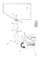
- FIG. 1 shows a device 10 for ventilating a motor vehicle, and in particular the passenger compartment 12 of the motor vehicle.
- This device essentially comprises a fan unit 14, a mouth 16 for air diffusion in the passenger compartment and a ventilation duct 18 connecting the fan unit 14 to the air outlet mouth 16.
- the fan unit 14 comprises, as known per se, a centrifugal fan 20 and a set of flaps 22 ensuring a channeling of the air flow generated by the fan through heating or cooling elements.
- the fan unit has an outlet 24 for discharging the air flow to which a first inlet end 26 of the duct 18 is connected.
- the second end denoted 28 of the duct 18 forms the air diffusion mouth 16.
- the diffusion mouth 16 is advantageously equipped with fins for guiding the air flow in the passenger compartment.
- the conduit 18 shown in FIG. 1 is devoid of bifurcations and directly connects the intake end 26 to the diffusion end 28.
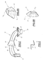
- the duct generally has a rectangular section, the edges being rounded, as illustrated in FIG. 2.
- the ventilation duct has a nominal cross section which is substantially constant along the entire length of the duct. This nominal cross section is for example equal to 3300 mm 2 .
- the conduit successively has two expansion chambers 30, 32 each having, along their length, a cross section greater than the nominal cross section of the conduit.
- An upstream section 36 of nominal cross section connects the inlet inlet 26 to the first chamber 30.
- a downstream section 38 of nominal cross section extends the second chamber 32 to the diffusion outlet 28.
- Each chamber 30, 32 has a progressively decreasing section according to the direction of flow of the air in the duct, that is to say from the inlet 26 towards the outlet 28.
- the chambers 30 and 32 have a generally frustoconical shape, the axis of which is oriented generally along the direction of flow of the air.
- the section of the downstream end of each chamber considering the direction of flow of the gas, is equal to the nominal section of the duct.
- the section of each chamber, at its upstream end, is, on the contrary, greater than the nominal section of the duct. This is in particular between two and eight times the nominal cross section of the duct and preferably between three and five times the nominal cross section of the duct.
- the upstream cross sections S 1 and S 1 'of the expansion chambers 30 and 32 are equal to 14000 mm 2 , the sections S 2 , S 2 ' expansion chambers 30, 32 being equal to 3300 mm 2 and 3500 mm 2, respectively .
- the current sections 36, 34 of the conduit communicate with the expansion chambers 30, 32 substantially at the center of the enlarged cross section upstream of the chamber.
- conduit 18 widens outwards in the expansion chambers 30, 32 along its entire periphery.
- connection fillets 40 in order to reduce the pressure losses along the duct and not to cause aeraulic turbulence, the variations in cross section between the current sections of the duct and the chambers have connection fillets 40, as illustrated in FIG. 4.
- the radius of these leaves is usually of the order of 1 to 3 mm.
- the expansion chambers create, in the direction of flow of the exhaust gases, a sudden variation in section obtained by the fronts 42 forming the upstream faces of the expansion chambers, these fronts generally extending perpendicular to the direction d exhaust gas flow.
- the lengths of the two chambers 30, 32 measured along the direction of flow of the fluids are between half and twice the nominal diameter of the conduit, that is to say the diameter of a disc whose surface is equal to the nominal cross section of the conduit.
- the length of the first and second chambers 30, 32 is equal to 86 mm and 43 mm, respectively.
- each room is chosen according to the frequency band over which the noise must be attenuated.
- the use of a pair of expansion chambers makes it possible, by coupling, to have a noise reduction effect over a wide frequency band, this bandwidth being greater than the sum of the two bandwidths on which each chamber acts. taken in isolation.
- the ventilation noise is particularly attenuated on the frequency band from 1 to 2 kHz.
- the generally frustoconical shape of the chambers and their orientation relative to the direction of flow of the fluid makes it possible to obtain a good compromise between the desired acoustic effect and the air pressure drop added by the chambers on the one hand and the acoustic effect desired and the creation of additional harmful noise sources due to the turbulence created by the chambers in the duct, on the other hand.
Abstract
Description
La présente invention concerne un dispositif de ventilation d'un véhicule automobile, du type comportant un groupe motoventilateur apte à propulser un flux d'air et un conduit de ventilation ayant, sur l'essentiel de sa longueur, une section transversale nominale, une première extrémité du conduit étant reliée en sortie du groupe motoventilateur et une seconde extrémité du conduit formant une bouche de diffusion d'air.The present invention relates to a ventilation device of a motor vehicle, of the type comprising a fan unit capable of propelling an air flow and a ventilation duct having, over most of its length, a nominal cross section, a first end of the duct being connected at the outlet of the fan unit and a second end of the duct forming an air diffusion mouth.
De nos jours, les véhicules automobiles sont équipés de dispositifs de ventilation permettant de réguler la température de l'habitacle du véhicule, en injectant dans l'habitacle un flux d'air chauffé ou refroidi suivant la température désirée.Nowadays, motor vehicles are equipped with ventilation devices making it possible to regulate the temperature of the passenger compartment of the vehicle, by injecting into the passenger compartment a flow of air heated or cooled according to the desired temperature.
Afin d'assurer la circulation du flux d'air jusque dans l'habitacle, le dispositif de ventilation comporte un groupe motoventilateur relié par un conduit de ventilation à une bouche de diffusion d'air dans l'habitacle.In order to ensure the circulation of the air flow into the passenger compartment, the ventilation device comprises a fan unit connected by a ventilation duct to an air diffusion mouth in the passenger compartment.
Le conduit de ventilation transmet, à l'intérieur de l'habitacle, le bruit en provenance du groupe motoventilateur. En effet, ce dernier est généralement équipé d'un ventilateur centrifuge ou pulseur qui engendre des bruits importants et gênants à basse fréquence, notamment dans la plage de 0 à 2500 Hz.The ventilation duct transmits, inside the passenger compartment, the noise coming from the fan unit. Indeed, the latter is generally equipped with a centrifugal fan or pulser which generates significant and annoying noises at low frequency, in particular in the range from 0 to 2500 Hz.
Il est connu, pour atténuer la propagation du bruit, d'implanter dans le conduit de ventilation des éléments absorbants acoustiques. Ceux-ci sont constitués par exemple de plaques de mousse.To reduce the propagation of noise, it is known to install acoustic absorbing elements in the ventilation duct. These consist for example of foam plates.
La mise en oeuvre de tels éléments absorbants complique le procédé de fabrication des conduits de ventilation puisqu'ils nécessitent le découpage et le collage de ces éléments absorbants contre le conduit.The implementation of such absorbent elements complicates the manufacturing process for ventilation ducts since they require cutting and bonding of these absorbent elements against the duct.
L'invention a pour but de proposer un dispositif de ventilation pour un véhicule automobile qui soit peu bruyant, et dont la fabrication est aisée.The object of the invention is to propose a ventilation device for a motor vehicle which is not very noisy, and whose manufacture is easy.
A cet effet, l'invention a pour objet un dispositif de ventilation d'un véhicule automobile du type précité, caractérisé en ce que le conduit comporte, entre le groupe motoventilateur et ladite bouche, au moins une chambre d'expansion disposée suivant la longueur du conduit entre deux tronçons adjacents de section transversale nominale, la ou chaque chambre d'expansion ayant une section transversale supérieure à ladite section transversale nominale.To this end, the subject of the invention is a ventilation device for a motor vehicle of the aforementioned type, characterized in that the duct comprises, between the fan unit and said mouth, at least one expansion chamber arranged along the length of the conduit between two adjacent sections of nominal cross section, the or each expansion chamber having a cross section greater than said nominal cross section.
Suivant des modes particuliers de réalisation, le dispositif de ventilation comporte l'une ou plusieurs des caractéristiques suivantes :
- ledit conduit comporte deux chambres d'expansion disposées successivement, reliées l'une à l'autre par un tronçon de section transversale nominale ;
- la ou chaque chambre présente une section progressivement décroissante suivant la longueur du conduit du groupe motoventilateur vers la bouche de diffusion d'air ;
- la ou chaque chambre présente une section progressivement décroissante jusqu'à ladite section transversale nominale ;
- les variations de la section du conduit suivant sa longueur présentent des congés de raccordement ;
- la section transversale maximale de la ou chaque chambre est comprise entre deux et huit fois la section transversale nominale ; et
- la longueur de la ou chaque chambre mesurée suivant la direction d'écoulement dans le conduit est comprise entre la moitié et le double du diamètre d'un disque ayant une surface égale à la section transversale nominale du conduit.
- said conduit comprises two expansion chambers arranged successively, connected to each other by a section of nominal cross section;
- the or each chamber has a progressively decreasing section along the length of the duct from the fan unit to the air diffusion mouth;
- the or each chamber has a progressively decreasing section up to said nominal cross section;
- variations in the section of the duct along its length have connection leave;
- the maximum cross section of the or each chamber is between two and eight times the nominal cross section; and
- the length of the or each chamber measured along the direction of flow in the conduit is between half and twice the diameter of a disc having an area equal to the nominal cross section of the conduit.
L'invention sera mieux comprise à la lecture de la description qui va suivre, donnée uniquement à titre d'exemple et faite en se référant aux dessins, sur lesquels :
- la figure 1 est une vue schématique en coupe longitudinale d'un dispositif de ventilation d'un véhicule automobile selon l'invention ;
- la figure 2 est une vue en perspective du conduit de ventilation du dispositif de la figure 1 ;
- les figures 3A et 3B sont des vues en perspective des première et seconde chambres d'expansion ménagées suivant la longueur du conduit de la figure 2 ; et
- la figure 4 est une vue en coupe longitudinale à plus grande échelle de la région de raccordement entre un tronçon courant du conduit et une chambre d'expansion désignée par IV sur la figure 2.
- Figure 1 is a schematic view in longitudinal section of a ventilation device of a motor vehicle according to the invention;
- Figure 2 is a perspective view of the ventilation duct of the device of Figure 1;
- Figures 3A and 3B are perspective views of the first and second expansion chambers formed along the length of the conduit of Figure 2; and
- FIG. 4 is a view in longitudinal section on a larger scale of the region of connection between a current section of the conduit and an expansion chamber designated by IV in FIG. 2.
Sur la figure 1 est représenté un dispositif 10 de ventilation d'un véhicule automobile, et notamment de l'habitacle 12 du véhicule automobile.FIG. 1 shows a
Ce dispositif comporte essentiellement un groupe motoventilateur 14, une bouche 16 de diffusion de l'air dans l'habitacle et un conduit de ventilation 18 reliant le groupe motoventilateur 14 à la bouche de diffusion d'air 16.This device essentially comprises a fan unit 14, a
Le groupe motoventilateur 14 comporte, comme connu en soi, un ventilateur centrifuge 20 et un ensemble de volets 22 assurant une canalisation du flux d'air engendré par le ventilateur au travers d'éléments chauffants ou réfrigérants. Le groupe motoventilateur présente une sortie 24 d'évacuation du flux d'air à laquelle est reliée une première extrémité 26 d'admission du conduit 18.The fan unit 14 comprises, as known per se, a
La seconde extrémité notée 28 du conduit 18 forme la bouche de diffusion d'air 16. La bouche de diffusion 16 est avantageusement équipée d'ailettes de guidage du flux d'air dans l'habitacle.The second end denoted 28 of the
Le conduit 18 représenté sur la figure 1 est dépourvu de bifurcations et relie directement l'extrémité d'admission 26 à l'extrémité de diffusion 28.The
Le conduit a généralement une section rectangulaire, les arêtes étant arrondies, comme illustré sur la figure 2. Le conduit de ventilation présente une section transversale nominale qui est sensiblement constante suivant toute la longueur du conduit. Cette section transversale nominale est par exemple égale à 3300 mm2.The duct generally has a rectangular section, the edges being rounded, as illustrated in FIG. 2. The ventilation duct has a nominal cross section which is substantially constant along the entire length of the duct. This nominal cross section is for example equal to 3300 mm 2 .
En outre, suivant sa longueur, le conduit présente successivement deux chambres d'expansion 30, 32 ayant chacune suivant leur longueur une section transversale supérieure à la section transversale nominale du conduit.In addition, along its length, the conduit successively has two
Ces deux chambres d'expansion sont reliées l'une à l'autre suivant la longueur du conduit 18 par un tronçon de liaison 34 de section transversale nominale.These two expansion chambers are connected to each other along the length of the
Un tronçon amont 36 de section transversale nominale relie l'entrée d'admission 26 à la première chambre 30. De même, un tronçon aval 38 de section transversale nominale prolonge la deuxième chambre 32 jusqu'à la sortie de diffusion 28.An
Chaque chambre 30, 32 présente une section progressivement décroissante suivant le sens d'écoulement de l'air dans le conduit, c'est-à-dire de l'entrée 26 vers la sortie 28.Each
Les chambres 30 et 32 présentent une forme générale tronconique, dont l'axe est orienté généralement suivant la direction d'écoulement de l'air.The
Plus précisément, la section de l'extrémité aval de chaque chambre, en considérant le sens d'écoulement du gaz, est égale à la section nominale du conduit. La section de chaque chambre, à son extrémité amont, est, au contraire, supérieure à la section nominale du conduit. Celle-ci est notamment comprise entre deux et huit fois la section transversale nominale du conduit et de préférence comprise entre trois et cinq fois la section transversale nominale du conduit.More precisely, the section of the downstream end of each chamber, considering the direction of flow of the gas, is equal to the nominal section of the duct. The section of each chamber, at its upstream end, is, on the contrary, greater than the nominal section of the duct. This is in particular between two and eight times the nominal cross section of the duct and preferably between three and five times the nominal cross section of the duct.
Dans le mode de réalisation envisagé, et comme illustré sur les figures 3A et 3B, les sections transversales amont S1 et S1' des chambres d'expansion 30 et 32 sont égales à 14000 mm2, les sections S2, S2' des chambres d'expansion 30, 32 étant égales, respectivement, à 3300 mm2 et 3500 mm2.In the embodiment envisaged, and as illustrated in FIGS. 3A and 3B, the upstream cross sections S 1 and S 1 'of the
Comme illustré aux figures, les tronçons courants 36, 34 du conduit communiquent avec les chambres d'expansion 30, 32 sensiblement au centre de la section transversale élargie amont de la chambre.As illustrated in the figures, the
Ainsi, le conduit 18 s'élargit vers l'extérieur dans les chambres d'expansion 30, 32 suivant toute sa périphérie.Thus, the
Avantageusement, afin de réduire les pertes de charge le long du conduit et de ne pas occasionner de turbulences aérauliques, les variations de section transversale entre les tronçons courants du conduit et les chambres présentent des congés de raccordement 40, comme illustré sur la figure 4. Le rayon de ces congés est usuellement de l'ordre de 1 à 3 mm.Advantageously, in order to reduce the pressure losses along the duct and not to cause aeraulic turbulence, the variations in cross section between the current sections of the duct and the chambers have
Les chambres d'expansion créent, suivant le sens d'écoulement des gaz d'échappement, une variation brutale de section obtenue par les fronts 42 formant les faces amont des chambres d'expansion, ces fronts s'étendant généralement perpendiculairement à la direction d'écoulement des gaz d'échappement.The expansion chambers create, in the direction of flow of the exhaust gases, a sudden variation in section obtained by the
Les longueurs des deux chambres 30, 32 mesurées suivant la direction d'écoulement des fluides sont comprises entre la moitié et le double du diamètre nominal du conduit, c'est-à-dire du diamètre d'un disque dont la surface est égale à la section transversale nominale du conduit.The lengths of the two
En particulier, la longueur des première et deuxième chambres 30, 32 est égale, respectivement, à 86 mm et 43 mm.In particular, the length of the first and
Les dimensions de chaque chambre sont choisies en fonction de la bande de fréquence sur laquelle le bruit doit être atténué. Le recours à une paire de chambres d'expansion permet, par couplage, d'avoir un effet de réduction du bruit sur une large bande de fréquences, cette largeur de bande étant supérieure à la somme des deux largeurs de bande sur lesquelles agit chaque chambre prise isolément.The dimensions of each room are chosen according to the frequency band over which the noise must be attenuated. The use of a pair of expansion chambers makes it possible, by coupling, to have a noise reduction effect over a wide frequency band, this bandwidth being greater than the sum of the two bandwidths on which each chamber acts. taken in isolation.
Ainsi, avec les dimensions données précédemment, le bruit de ventilation est particulièrement atténué sur la bande de fréquences de 1 à 2 kHz.Thus, with the dimensions given above, the ventilation noise is particularly attenuated on the frequency band from 1 to 2 kHz.
On comprend que la présence de chambres d'expansion suivant la longueur du conduit diminue le coefficient de transmission de l'onde acoustique se propageant suivant le conduit. Ainsi, le bruit engendré par le groupe motoventilateur transmis à l'habitacle est réduit.It is understood that the presence of expansion chambers along the length of the conduit reduces the transmission coefficient of the acoustic wave propagating along the conduit. Thus, the noise generated by the fan unit transmitted to the passenger compartment is reduced.
La forme généralement tronconique des chambres et leur orientation par rapport au sens d'écoulement du fluide permet d'obtenir un bon compromis entre l'effet acoustique désiré et la perte de charge aéraulique ajoutée par les chambres d'une part et l'effet acoustique désiré et la création de sources de bruit supplémentaires nuisibles dues aux turbulences créées par les chambres dans le conduit, d'autre part.The generally frustoconical shape of the chambers and their orientation relative to the direction of flow of the fluid makes it possible to obtain a good compromise between the desired acoustic effect and the air pressure drop added by the chambers on the one hand and the acoustic effect desired and the creation of additional harmful noise sources due to the turbulence created by the chambers in the duct, on the other hand.
Claims (6)
Applications Claiming Priority (2)
| Application Number | Priority Date | Filing Date | Title |
|---|---|---|---|
| FR0211938 | 2002-09-26 | ||
| FR0211938A FR2845033B1 (en) | 2002-09-26 | 2002-09-26 | DEVICE FOR VENTILATION OF A MOTOR VEHICLE |
Publications (2)
| Publication Number | Publication Date |
|---|---|
| EP1403105A1 true EP1403105A1 (en) | 2004-03-31 |
| EP1403105B1 EP1403105B1 (en) | 2006-03-29 |
Family
ID=31971006
Family Applications (1)
| Application Number | Title | Priority Date | Filing Date |
|---|---|---|---|
| EP03292332A Expired - Lifetime EP1403105B1 (en) | 2002-09-26 | 2003-09-23 | Ventilation device for a motor vehicle |
Country Status (5)
| Country | Link |
|---|---|
| EP (1) | EP1403105B1 (en) |
| AT (1) | ATE321678T1 (en) |
| DE (1) | DE60304308T2 (en) |
| ES (1) | ES2263932T3 (en) |
| FR (1) | FR2845033B1 (en) |
Cited By (6)
| Publication number | Priority date | Publication date | Assignee | Title |
|---|---|---|---|---|
| FR2871872A1 (en) * | 2004-06-18 | 2005-12-23 | Renault Sas | Ventilation duct for ventilation and/or air-conditioning system of e.g. motor vehicle, has noise attenuation unit with acoustic cavity formed by enlargement, of passage section of fluid flow path, with upstream and downstream transitions |
| WO2007045778A1 (en) | 2005-10-20 | 2007-04-26 | Renault S.A.S. | Motor vehicle ventilating device comprising noise abating means |
| EP1916424A3 (en) * | 2006-10-25 | 2012-08-01 | Valeo Klimasysteme GmbH | Ventilation system with sound barrier |
| CN105593534A (en) * | 2013-09-26 | 2016-05-18 | 阿尔弗雷德·凯驰两合公司 | Suction device with sound mirror device |
| CN108688432A (en) * | 2017-03-29 | 2018-10-23 | 福特全球技术公司 | Acoustics air flue and extract system with nested expanding chamber |
| FR3128775A1 (en) | 2021-10-29 | 2023-05-05 | Sofitec | Air diffusion duct with high acoustic performance, in particular for motor vehicles |
Families Citing this family (2)
| Publication number | Priority date | Publication date | Assignee | Title |
|---|---|---|---|---|
| DE102004046058A1 (en) * | 2004-09-21 | 2006-03-23 | Behr Gmbh & Co. Kg | Connection of two air-conducting components of a ventilation system, in particular a motor vehicle ventilation system |
| DE102020006479A1 (en) * | 2020-10-21 | 2022-04-21 | Truma Gerätetechnik GmbH & Co. KG | temperature control device |
Citations (4)
| Publication number | Priority date | Publication date | Assignee | Title |
|---|---|---|---|---|
| JPS6099948A (en) * | 1983-11-02 | 1985-06-03 | Nippon Denso Co Ltd | Sound silencing blow-off port for air-conditioning device |
| FR2712851A1 (en) * | 1993-11-23 | 1995-06-02 | Illbruck Sa | Ventilation duct with foam noise attenuator |
| EP0787607A2 (en) * | 1995-09-08 | 1997-08-06 | Trinova GmbH | Sound damping device |
| US6112850A (en) * | 1999-09-07 | 2000-09-05 | Met Pro Corporation | Acoustic silencer nozzle |
-
2002
- 2002-09-26 FR FR0211938A patent/FR2845033B1/en not_active Expired - Fee Related
-
2003
- 2003-09-23 DE DE60304308T patent/DE60304308T2/en not_active Expired - Fee Related
- 2003-09-23 EP EP03292332A patent/EP1403105B1/en not_active Expired - Lifetime
- 2003-09-23 AT AT03292332T patent/ATE321678T1/en not_active IP Right Cessation
- 2003-09-23 ES ES03292332T patent/ES2263932T3/en not_active Expired - Lifetime
Patent Citations (4)
| Publication number | Priority date | Publication date | Assignee | Title |
|---|---|---|---|---|
| JPS6099948A (en) * | 1983-11-02 | 1985-06-03 | Nippon Denso Co Ltd | Sound silencing blow-off port for air-conditioning device |
| FR2712851A1 (en) * | 1993-11-23 | 1995-06-02 | Illbruck Sa | Ventilation duct with foam noise attenuator |
| EP0787607A2 (en) * | 1995-09-08 | 1997-08-06 | Trinova GmbH | Sound damping device |
| US6112850A (en) * | 1999-09-07 | 2000-09-05 | Met Pro Corporation | Acoustic silencer nozzle |
Non-Patent Citations (1)
| Title |
|---|
| PATENT ABSTRACTS OF JAPAN vol. 009, no. 249 (M - 419) 5 October 1985 (1985-10-05) * |
Cited By (8)
| Publication number | Priority date | Publication date | Assignee | Title |
|---|---|---|---|---|
| FR2871872A1 (en) * | 2004-06-18 | 2005-12-23 | Renault Sas | Ventilation duct for ventilation and/or air-conditioning system of e.g. motor vehicle, has noise attenuation unit with acoustic cavity formed by enlargement, of passage section of fluid flow path, with upstream and downstream transitions |
| WO2007045778A1 (en) | 2005-10-20 | 2007-04-26 | Renault S.A.S. | Motor vehicle ventilating device comprising noise abating means |
| FR2892344A1 (en) | 2005-10-20 | 2007-04-27 | Renault Sas | DEVICE FOR VENTILATION OF A MOTOR VEHICLE COMPRISING NOISE MITIGATION MEANS |
| EP1916424A3 (en) * | 2006-10-25 | 2012-08-01 | Valeo Klimasysteme GmbH | Ventilation system with sound barrier |
| CN105593534A (en) * | 2013-09-26 | 2016-05-18 | 阿尔弗雷德·凯驰两合公司 | Suction device with sound mirror device |
| US10184491B2 (en) | 2013-09-26 | 2019-01-22 | Alfred Kärcher SE & Co. KG | Suction device with sound mirror device |
| CN108688432A (en) * | 2017-03-29 | 2018-10-23 | 福特全球技术公司 | Acoustics air flue and extract system with nested expanding chamber |
| FR3128775A1 (en) | 2021-10-29 | 2023-05-05 | Sofitec | Air diffusion duct with high acoustic performance, in particular for motor vehicles |
Also Published As
| Publication number | Publication date |
|---|---|
| DE60304308D1 (en) | 2006-05-18 |
| FR2845033B1 (en) | 2006-02-17 |
| ES2263932T3 (en) | 2006-12-16 |
| ATE321678T1 (en) | 2006-04-15 |
| EP1403105B1 (en) | 2006-03-29 |
| DE60304308T2 (en) | 2006-11-09 |
| FR2845033A1 (en) | 2004-04-02 |
Similar Documents
| Publication | Publication Date | Title |
|---|---|---|
| EP1070903B1 (en) | Device for attenuating noise in a pipe carrying gas | |
| EP2763892B1 (en) | Method of manufacturing a sound absorbing panel | |
| EP1403105B1 (en) | Ventilation device for a motor vehicle | |
| EP1010884B1 (en) | Turbomachine multi-annular exhaust duct with acoustic lining | |
| FR2607868A1 (en) | MUFFLER FOR A VEHICLE GAS EXHAUST DEVICE, COMPRISING PLATES TO DIRECT THEIR CIRCULATION | |
| WO2016169834A1 (en) | Muffler having a main casing and a partial casing, and method for manufacturing such a muffler | |
| EP3963192A1 (en) | Integration of a fan flutter damper in an engine casing | |
| EP1864838B1 (en) | Noise-reduction device for automobile air-conditioning circuit, conduit and circuit comprising same | |
| EP2894414B1 (en) | Ventilation unit with sound trap | |
| FR2876172A1 (en) | Acoustic attenuation duct device for ventilation of an automobile vehicle, includes an opening and an ensemble having foam/fibrous/porous layer, external sheet, in which the periphery edge is fixed continuously and tightly on the duct | |
| EP1255071A1 (en) | Device for attenuating sound in a circuit for gaseous fluid | |
| WO2008110707A2 (en) | Ventilation duct including noise reduction means | |
| EP1433948B1 (en) | Air intake silencing device | |
| FR2998267A1 (en) | Nacelle for turbojet of plane such as commercial transport aircraft, has Herschel-Quincke tube with constant curve over its length, where tube emerges at its two ends on interior of nacelle through set of perforated walls | |
| EP1553284B1 (en) | Air intake silencing device especially for turbocharged engines or air conditioner and intake circuit with such a device | |
| EP1712382B1 (en) | Ventilation device for a vehicle including noise reduction means | |
| FR2927952A1 (en) | Quasi-cylindrical sound-insulation wall for turbojet engine nacelle in airplane, has alveolar structure with cylindrical configuration without discontinuity, and carried by another structure formed of juxtaposed sectors fixed end to end | |
| EP2292967A2 (en) | Sound attenuating device | |
| WO2023198984A1 (en) | Acoustic treatment device for a heating, ventilation and/or air-conditioning system | |
| EP1369577B1 (en) | Air intake silencing device especially for turbocharged engines or air conditioner and intake circuit with such a device | |
| FR3073564B1 (en) | VENTILATION DEVICE FOR MOTOR VEHICLE | |
| WO2024079238A1 (en) | Acoustic treatment device for ventilation system | |
| FR2871872A1 (en) | Ventilation duct for ventilation and/or air-conditioning system of e.g. motor vehicle, has noise attenuation unit with acoustic cavity formed by enlargement, of passage section of fluid flow path, with upstream and downstream transitions | |
| FR3121195A1 (en) | Conduit for circulation of a gaseous fluid comprising a sound-absorbing coating | |
| FR3082566A1 (en) | INLET CONE AND HEAT EXCHANGER OF AN EXHAUST GAS RECIRCULATION LINE, CORRESPONDING ASSEMBLY |
Legal Events
| Date | Code | Title | Description |
|---|---|---|---|
| PUAI | Public reference made under article 153(3) epc to a published international application that has entered the european phase |
Free format text: ORIGINAL CODE: 0009012 |
|
| AK | Designated contracting states |
Kind code of ref document: A1 Designated state(s): AT BE BG CH CY CZ DE DK EE ES FI FR GB GR HU IE IT LI LU MC NL PT RO SE SI SK TR |
|
| AX | Request for extension of the european patent |
Extension state: AL LT LV MK |
|
| 17P | Request for examination filed |
Effective date: 20040911 |
|
| AKX | Designation fees paid |
Designated state(s): AT BE BG CH CY CZ DE DK EE ES FI FR GB GR HU IE IT LI LU MC NL PT RO SE SI SK TR |
|
| GRAP | Despatch of communication of intention to grant a patent |
Free format text: ORIGINAL CODE: EPIDOSNIGR1 |
|
| GRAS | Grant fee paid |
Free format text: ORIGINAL CODE: EPIDOSNIGR3 |
|
| GRAA | (expected) grant |
Free format text: ORIGINAL CODE: 0009210 |
|
| AK | Designated contracting states |
Kind code of ref document: B1 Designated state(s): AT BE BG CH CY CZ DE DK EE ES FI FR GB GR HU IE IT LI LU MC NL PT RO SE SI SK TR |
|
| PG25 | Lapsed in a contracting state [announced via postgrant information from national office to epo] |
Ref country code: SK Free format text: LAPSE BECAUSE OF FAILURE TO SUBMIT A TRANSLATION OF THE DESCRIPTION OR TO PAY THE FEE WITHIN THE PRESCRIBED TIME-LIMIT Effective date: 20060329 Ref country code: NL Free format text: LAPSE BECAUSE OF FAILURE TO SUBMIT A TRANSLATION OF THE DESCRIPTION OR TO PAY THE FEE WITHIN THE PRESCRIBED TIME-LIMIT Effective date: 20060329 Ref country code: AT Free format text: LAPSE BECAUSE OF FAILURE TO SUBMIT A TRANSLATION OF THE DESCRIPTION OR TO PAY THE FEE WITHIN THE PRESCRIBED TIME-LIMIT Effective date: 20060329 Ref country code: IE Free format text: LAPSE BECAUSE OF FAILURE TO SUBMIT A TRANSLATION OF THE DESCRIPTION OR TO PAY THE FEE WITHIN THE PRESCRIBED TIME-LIMIT Effective date: 20060329 Ref country code: SI Free format text: LAPSE BECAUSE OF FAILURE TO SUBMIT A TRANSLATION OF THE DESCRIPTION OR TO PAY THE FEE WITHIN THE PRESCRIBED TIME-LIMIT Effective date: 20060329 Ref country code: RO Free format text: LAPSE BECAUSE OF FAILURE TO SUBMIT A TRANSLATION OF THE DESCRIPTION OR TO PAY THE FEE WITHIN THE PRESCRIBED TIME-LIMIT Effective date: 20060329 |
|
| REG | Reference to a national code |
Ref country code: GB Ref legal event code: FG4D Free format text: NOT ENGLISH |
|
| REG | Reference to a national code |
Ref country code: CH Ref legal event code: EP |
|
| GBT | Gb: translation of ep patent filed (gb section 77(6)(a)/1977) |
Effective date: 20060406 |
|
| REG | Reference to a national code |
Ref country code: IE Ref legal event code: FG4D Free format text: LANGUAGE OF EP DOCUMENT: FRENCH |
|
| REF | Corresponds to: |
Ref document number: 60304308 Country of ref document: DE Date of ref document: 20060518 Kind code of ref document: P |
|
| PG25 | Lapsed in a contracting state [announced via postgrant information from national office to epo] |
Ref country code: DK Free format text: LAPSE BECAUSE OF FAILURE TO SUBMIT A TRANSLATION OF THE DESCRIPTION OR TO PAY THE FEE WITHIN THE PRESCRIBED TIME-LIMIT Effective date: 20060629 Ref country code: BG Free format text: LAPSE BECAUSE OF FAILURE TO SUBMIT A TRANSLATION OF THE DESCRIPTION OR TO PAY THE FEE WITHIN THE PRESCRIBED TIME-LIMIT Effective date: 20060629 Ref country code: SE Free format text: LAPSE BECAUSE OF FAILURE TO SUBMIT A TRANSLATION OF THE DESCRIPTION OR TO PAY THE FEE WITHIN THE PRESCRIBED TIME-LIMIT Effective date: 20060629 |
|
| PG25 | Lapsed in a contracting state [announced via postgrant information from national office to epo] |
Ref country code: PT Free format text: LAPSE BECAUSE OF FAILURE TO SUBMIT A TRANSLATION OF THE DESCRIPTION OR TO PAY THE FEE WITHIN THE PRESCRIBED TIME-LIMIT Effective date: 20060829 |
|
| PG25 | Lapsed in a contracting state [announced via postgrant information from national office to epo] |
Ref country code: MC Free format text: LAPSE BECAUSE OF NON-PAYMENT OF DUE FEES Effective date: 20060930 Ref country code: BE Free format text: LAPSE BECAUSE OF NON-PAYMENT OF DUE FEES Effective date: 20060930 |
|
| NLV1 | Nl: lapsed or annulled due to failure to fulfill the requirements of art. 29p and 29m of the patents act | ||
| REG | Reference to a national code |
Ref country code: IE Ref legal event code: FD4D |
|
| REG | Reference to a national code |
Ref country code: ES Ref legal event code: FG2A Ref document number: 2263932 Country of ref document: ES Kind code of ref document: T3 |
|
| PLBE | No opposition filed within time limit |
Free format text: ORIGINAL CODE: 0009261 |
|
| STAA | Information on the status of an ep patent application or granted ep patent |
Free format text: STATUS: NO OPPOSITION FILED WITHIN TIME LIMIT |
|
| 26N | No opposition filed |
Effective date: 20070102 |
|
| BERE | Be: lapsed |
Owner name: PEUGEOT CITROEN AUTOMOBILES SA Effective date: 20060930 |
|
| PG25 | Lapsed in a contracting state [announced via postgrant information from national office to epo] |
Ref country code: CZ Free format text: LAPSE BECAUSE OF FAILURE TO SUBMIT A TRANSLATION OF THE DESCRIPTION OR TO PAY THE FEE WITHIN THE PRESCRIBED TIME-LIMIT Effective date: 20060329 Ref country code: GR Free format text: LAPSE BECAUSE OF FAILURE TO SUBMIT A TRANSLATION OF THE DESCRIPTION OR TO PAY THE FEE WITHIN THE PRESCRIBED TIME-LIMIT Effective date: 20060630 |
|
| REG | Reference to a national code |
Ref country code: CH Ref legal event code: PL |
|
| PG25 | Lapsed in a contracting state [announced via postgrant information from national office to epo] |
Ref country code: FI Free format text: LAPSE BECAUSE OF FAILURE TO SUBMIT A TRANSLATION OF THE DESCRIPTION OR TO PAY THE FEE WITHIN THE PRESCRIBED TIME-LIMIT Effective date: 20060329 Ref country code: EE Free format text: LAPSE BECAUSE OF FAILURE TO SUBMIT A TRANSLATION OF THE DESCRIPTION OR TO PAY THE FEE WITHIN THE PRESCRIBED TIME-LIMIT Effective date: 20060329 |
|
| PG25 | Lapsed in a contracting state [announced via postgrant information from national office to epo] |
Ref country code: TR Free format text: LAPSE BECAUSE OF FAILURE TO SUBMIT A TRANSLATION OF THE DESCRIPTION OR TO PAY THE FEE WITHIN THE PRESCRIBED TIME-LIMIT Effective date: 20060329 Ref country code: CH Free format text: LAPSE BECAUSE OF NON-PAYMENT OF DUE FEES Effective date: 20070930 Ref country code: LU Free format text: LAPSE BECAUSE OF NON-PAYMENT OF DUE FEES Effective date: 20060923 Ref country code: HU Free format text: LAPSE BECAUSE OF FAILURE TO SUBMIT A TRANSLATION OF THE DESCRIPTION OR TO PAY THE FEE WITHIN THE PRESCRIBED TIME-LIMIT Effective date: 20060930 Ref country code: LI Free format text: LAPSE BECAUSE OF NON-PAYMENT OF DUE FEES Effective date: 20070930 |
|
| PGFP | Annual fee paid to national office [announced via postgrant information from national office to epo] |
Ref country code: ES Payment date: 20080924 Year of fee payment: 6 |
|
| PG25 | Lapsed in a contracting state [announced via postgrant information from national office to epo] |
Ref country code: CY Free format text: LAPSE BECAUSE OF FAILURE TO SUBMIT A TRANSLATION OF THE DESCRIPTION OR TO PAY THE FEE WITHIN THE PRESCRIBED TIME-LIMIT Effective date: 20060329 |
|
| PGFP | Annual fee paid to national office [announced via postgrant information from national office to epo] |
Ref country code: IT Payment date: 20080913 Year of fee payment: 6 |
|
| PGFP | Annual fee paid to national office [announced via postgrant information from national office to epo] |
Ref country code: GB Payment date: 20080827 Year of fee payment: 6 |
|
| PGFP | Annual fee paid to national office [announced via postgrant information from national office to epo] |
Ref country code: DE Payment date: 20081002 Year of fee payment: 6 |
|
| PGFP | Annual fee paid to national office [announced via postgrant information from national office to epo] |
Ref country code: FR Payment date: 20080929 Year of fee payment: 6 |
|
| GBPC | Gb: european patent ceased through non-payment of renewal fee |
Effective date: 20090923 |
|
| REG | Reference to a national code |
Ref country code: FR Ref legal event code: ST Effective date: 20100531 |
|
| PG25 | Lapsed in a contracting state [announced via postgrant information from national office to epo] |
Ref country code: DE Free format text: LAPSE BECAUSE OF NON-PAYMENT OF DUE FEES Effective date: 20100401 Ref country code: FR Free format text: LAPSE BECAUSE OF NON-PAYMENT OF DUE FEES Effective date: 20090930 |
|
| PG25 | Lapsed in a contracting state [announced via postgrant information from national office to epo] |
Ref country code: GB Free format text: LAPSE BECAUSE OF NON-PAYMENT OF DUE FEES Effective date: 20090923 |
|
| PG25 | Lapsed in a contracting state [announced via postgrant information from national office to epo] |
Ref country code: IT Free format text: LAPSE BECAUSE OF NON-PAYMENT OF DUE FEES Effective date: 20090923 |
|
| REG | Reference to a national code |
Ref country code: ES Ref legal event code: FD2A Effective date: 20110711 |
|
| PG25 | Lapsed in a contracting state [announced via postgrant information from national office to epo] |
Ref country code: ES Free format text: LAPSE BECAUSE OF NON-PAYMENT OF DUE FEES Effective date: 20110629 |
|
| PG25 | Lapsed in a contracting state [announced via postgrant information from national office to epo] |
Ref country code: ES Free format text: LAPSE BECAUSE OF NON-PAYMENT OF DUE FEES Effective date: 20090924 |