EP1403056B1 - Fluid containment system including an ink redirection surface - Google Patents
Fluid containment system including an ink redirection surface Download PDFInfo
- Publication number
- EP1403056B1 EP1403056B1 EP03007803A EP03007803A EP1403056B1 EP 1403056 B1 EP1403056 B1 EP 1403056B1 EP 03007803 A EP03007803 A EP 03007803A EP 03007803 A EP03007803 A EP 03007803A EP 1403056 B1 EP1403056 B1 EP 1403056B1
- Authority
- EP
- European Patent Office
- Prior art keywords
- ink
- area
- opening
- depository
- hood
- Prior art date
- Legal status (The legal status is an assumption and is not a legal conclusion. Google has not performed a legal analysis and makes no representation as to the accuracy of the status listed.)
- Expired - Fee Related
Links
Images


Classifications
-
- B—PERFORMING OPERATIONS; TRANSPORTING
- B41—PRINTING; LINING MACHINES; TYPEWRITERS; STAMPS
- B41J—TYPEWRITERS; SELECTIVE PRINTING MECHANISMS, i.e. MECHANISMS PRINTING OTHERWISE THAN FROM A FORME; CORRECTION OF TYPOGRAPHICAL ERRORS
- B41J2/00—Typewriters or selective printing mechanisms characterised by the printing or marking process for which they are designed
- B41J2/005—Typewriters or selective printing mechanisms characterised by the printing or marking process for which they are designed characterised by bringing liquid or particles selectively into contact with a printing material
- B41J2/01—Ink jet
- B41J2/135—Nozzles
- B41J2/165—Preventing or detecting of nozzle clogging, e.g. cleaning, capping or moistening for nozzles
- B41J2/16505—Caps, spittoons or covers for cleaning or preventing drying out
- B41J2/16508—Caps, spittoons or covers for cleaning or preventing drying out connected with the printer frame
-
- B—PERFORMING OPERATIONS; TRANSPORTING
- B41—PRINTING; LINING MACHINES; TYPEWRITERS; STAMPS
- B41J—TYPEWRITERS; SELECTIVE PRINTING MECHANISMS, i.e. MECHANISMS PRINTING OTHERWISE THAN FROM A FORME; CORRECTION OF TYPOGRAPHICAL ERRORS
- B41J2/00—Typewriters or selective printing mechanisms characterised by the printing or marking process for which they are designed
- B41J2/005—Typewriters or selective printing mechanisms characterised by the printing or marking process for which they are designed characterised by bringing liquid or particles selectively into contact with a printing material
- B41J2/01—Ink jet
- B41J2/17—Ink jet characterised by ink handling
- B41J2/1721—Collecting waste ink; Collectors therefor
- B41J2002/1728—Closed waste ink collector
-
- B—PERFORMING OPERATIONS; TRANSPORTING
- B41—PRINTING; LINING MACHINES; TYPEWRITERS; STAMPS
- B41J—TYPEWRITERS; SELECTIVE PRINTING MECHANISMS, i.e. MECHANISMS PRINTING OTHERWISE THAN FROM A FORME; CORRECTION OF TYPOGRAPHICAL ERRORS
- B41J2/00—Typewriters or selective printing mechanisms characterised by the printing or marking process for which they are designed
- B41J2/005—Typewriters or selective printing mechanisms characterised by the printing or marking process for which they are designed characterised by bringing liquid or particles selectively into contact with a printing material
- B41J2/01—Ink jet
- B41J2/17—Ink jet characterised by ink handling
- B41J2/1721—Collecting waste ink; Collectors therefor
- B41J2002/1742—Open waste ink collector, e.g. ink receiving from a print head above the collector during borderless printing
Definitions
- Printing mechanisms such as inkjet printers, may use pens, which shoot drops of liquid colorant, referred to generally herein as "ink,” onto a print medium, such as a page of paper.
- pens which shoot drops of liquid colorant, referred to generally herein as "ink” onto a print medium, such as a page of paper.
- Each pen may have a printhead formed with very small nozzles through which the ink drops are fired.
- the printhead may be propelled back and forth across the page, shooting drops of ink in a desired pattern as it moves.
- the particular ink ejection mechanism within the printhead may be implemented in a variety of different ways, such as by piezo-electric or thermal printhead technology.
- a service station mechanism may be mounted within the printer. During cleaning the printhead may be moved over the service station and ink may be ejected or "purged" from the printhead nozzles toward a spittoon or ink collection chamber of the service station. The ejected ink may combine with surrounding air to create an ink aerosol that is not easily contained with the spittoon. The uncontained ink aerosol may damage internal components of the printing mechanism or contaminate sites within the printing mechanism such as the input or outputs trays, or print media held therein. In the case of color printing mechanisms, an ink aerosol from one colored ink printhead may emerge from the spittoon and contaminate an ink printhead of a different colored ink, thereby reducing the print quality of each image printed thereafter.
- EP 0 705 699 A1 discloses an inkjet printing mechanism and an inkjet printhead and a carriage to carry the printhead.
- the carriage is designed to move the printhead through a print zone to a service station where the printhead is serviced.
- the printhead ejects ink droplets at the service station to clear the printhead nozzle orifices prior to printing.
- a reservoir is provided at the service station to collect the ink droplets ejected from the printhead during the service mode.
- a venturi passageway is also positioned at the service station adjacent to the reservoir. The venturi passageway guides the ink droplets ejected from the printhead into the reservoir.
- US 2002/0033860 A1 discloses an inkjet recording apparatus, a head unit composed of a recording head and an ink tank being mounted on a carriage with an ejection port surface facing upward.
- the recording head records an image on a lower surface of a medium to be recorded by ejecting ink upwards from printing ports.
- a preliminary ejection receiver is disposed outside of a region where an image can be recorded on the medium to receive ink preliminary ejected from the recording head in order to maintain and recover an ink ejection performance of the recording head.
- the preliminary ejection receiver has an opening acting as an inlet for the preliminary ejected ink.
- a ceiling surface is disposed above the opening, wherein the ceiling surface inclines with respect to a horizontal direction and on which the ink preliminary ejected into the preliminary ejection receiver deposits.
- EP 1 000 743 A2 discloses an inkjet recording apparatus comprising a flashing signal generating unit that generates a flashing signal, a recording head provided with nozzles and capable of jetting ink particles through the nozzles when driven by the flashing signal.
- the flashing signal causes the recording head to jet only main ink particles through the nozzles.
- the inkjet recording apparatus suppresses the formation of mist of ink particles during a flashing operation.
- the inkjet recording apparatus provides an opening for cleaning the printhead nozzles by jetting ink onto an ink absorbing member, the opening being located opposite of a service station with respect to a print zone.
- a fluid containment system includes an ink depository and a hood secured thereto.
- the hood includes an ink redirection structure for directing ink emitted from a printhead through a constrictive conduit into the ink depository.
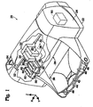
- FIG. 1 illustrates one embodiment of a printing mechanism, here shown as a printer 20, which may be used for the printing of business reports, correspondence, desktop publishing, and the like, in an industrial, office, home or other environment.
- a printing mechanism here shown as a printer 20, which may be used for the printing of business reports, correspondence, desktop publishing, and the like, in an industrial, office, home or other environment.
- a variety of printing mechanisms is commercially available, such as inkjet printers and laser printers, for example.
- Some of the printing mechanisms that may use embodiments of the present invention include plotters, portable printing units, copiers, cameras, video printers, and facsimile machines, to name a few.
- the concepts of the printing mechanism are illustrated in the environment of an inkjet printer 20.
- inkjet printer 20 may include a chassis 22 surrounded by a housing, also called a body or a casing enclosure 24, which may be manufactured of plastic.
- a sheet or sheets of print media may be fed through a print zone 26 and beneath a first printhead 28, also referred to as a printing means and an ink ejection device, and a second printhead 30.
- the one or more printheads may be supported on a printhead carriage 32 which is supported on a carriage rod 34 extending through the housing and defining a scanning axis 36.
- the print media sheet 38 or sheets may be any type of suitable material, such as paper, card-stock, cardboard, transparencies, mylar, and the like, but for convenience, the illustrated embodiment is described using paper as the print medium.
- sheet 38 is shown exiting print zone 26 and being deposited on an output tray 40 having a sliding length adjustment lever 42.
- an input tray 44 including a length adjustment device, such as a sliding length adjustment lever 46 and a width adjustment device, such as a sliding width adjustment lever 48, for accommodating different sizes of print media, including letter, legal, A-4, and envelopes, for example.
- An actuation device such as a motor 50 (shown schematically in dash lines), may be positioned within housing 24 and may operate to move printhead carriage 32 along carriage rod 34, in the direction of scanning axis 36, from print zone 26 into a servicing region 52.
- a capping station not shown, may be separately positioned on an opposite side of the printer, i.e., along carriage rod 34 and adjacent motor 50.
- a printer controller illustrated schematically as a microprocessor 54, may be positioned within housing 24 and may receive instructions from a host device, typically a computer, such as a personal computer (not shown) for operating motor 50 and printheads 28 and 30.
- printer controller 54 encompasses these functions, whether performed by the host computer, the printer, an intermediary device therebetween, or by a combined interaction of such elements.
- the printer controller 54 may also operate in response to user inputs provided through a key pad (not shown) located on an exterior of housing 24.
- a monitor coupled to the computer host may be used to display visual information to an operator, such as the printer status or a particular program being run on the host computer.
- service region 52 may comprise a service station 56, also referred to herein as a cleaning station or a maintenance station, movable into position adjacent printheads 28 and 30 when the printheads are moved into the service region.
- Service station 56 also referred to as a servicing means, may include a support sled 58 that movably supports an ink receiving means such as a first spittoon 60, which functions as an ink collection chamber.
- the support sled 58 may include wipers, wiper scrapers, and/or absorbers, not shown, that may be moved back and forth across the printheads to service the printheads 28 and 30.
- Actuation of the sled 58 may be accomplished with a drive gear and a mating gear rack, not shown, that may be positioned beneath the support sled.
- the support sled 58 may be held stationary adjacent the printhead 28 during "spitting" by the pens so that the printhead is properly aligned with its corresponding spittoon.
- the support sled 58 further includes a second spittoon 62 so that each of the printheads will align with a corresponding spittoon during the servicing routine.
- Each of the spittoons 60 and 62 may include a surface directing means, such as hoods 64 and 66, respectively, that change the trajectories of ink droplets emitted from printheads 20 and 30.
- FIG. 2 illustrates a side cross sectional view of one embodiment of the printing mechanism of FIG. 1, wherein a nozzle orifice plate 68 of first printhead 28 is positioned in servicing region 52, above and aligned with an upper hood opening 70 of first hood 64.
- Upper hood opening 70 has a perimeter 71 which defines an area A1 that may be sized and shaped to efficiently capture ink particles ejected from printhead 28.
- hood 64 includes an upper opening 70 defined by a guide structure 83 and a stop structure 82.
- Upper guide structure 83 has an upper guide surface 80 and an opposed underside surface 81.
- Stop structure 82 includes an upper surface 87 and an underside surface 89.
- Ink particles ejected from printhead 28 tend to form an aerosol that undesirably may become deposited on various components of printer 20. Therefore, capturing ink particles ejected from printhead 28 during servicing of the printhead is very desirable.
- area A1 is generally positioned proximate to printhead 28 so that ink particles ejected from printhead 28 may ejected through opening 70 of hood 64.
- area A1 is generally oriented perpendicularly to directional ray 90, and is shown edge-on in FIG 2. Ray 90 is also coincident with a normal of area A1, where a normal is defined as a line that is perpendicular to the plane defined by area A1.
- Hood 64 is secured to depository opening 72, of spittoon 60, and funnels ink particles ejected from the printhead 28 during servicing into reservoir 76 of spittoon 60.
- Opening 72 has a perimeter 74 that defines an area A2 of opening 72 which is generally perpendicular to direction ray 90.
- Area A2 may be quite large compared to area A1, and is shown edge-on in FIG. 2. By way of example, area A2 may be more than four times larger than the area A1.
- At least fifty percent, and in particular, approximately seventy five percent, of the area A2 may be blocked by the underside surface 81 of guide structure 83.
- at least eighty percent, and in particular, approximately ninety five percent, of the area A2 may be occluded or blocked by a combination of underside surface 81 and stop surface 82.
- the difference in size between areas A1 and A2 facilitates capturing or trapping any ink particles or ink aerosols that enter reservoir 76 of spittoon 60, as described below.
- Hood 64 includes underside surface 89 and deflection surface 91.
- Surface 89 generally meets and is coterminous with deflection surface 91 at an angles of about 90 degrees, although the scope of the invention includes joining these surfaces at other angles, as may be required to suit the needs of a particular application.
- Underside surface 81 and deflection surface 91 collectively define a lower hood opening 84 having a perimeter 86.
- Perimeter 86 defines area A3 of opening 84, where area A3 is represented edge-on as a line in Figure 2.
- Surfaces 80 and 89 extend between opening 70 and opening 84 to form a progressively narrow or constricted conduit 88.
- Area A1 of upper hood opening 70 may be large compared to area A3 of lower hood opening 84 and, in particular, the area A1 may be more than two times larger than area A3. Area A2 may be eight times larger than area A3.
- hood 64 defines a funnel shaped, constricted conduit 88 that extends and becomes progressively more restricted from opening 70 to opening 84.
- the underside surface 89 of stop structure 82 serves as a ridge that helps to inhibit the flow of any ink particles 78 out of hood 64 after they enter channel 88.
- the printhead may purge or eject ink particles 78 along a trajectory represented by directional ray 90, which may be oriented perpendicularly with respect to nozzle orifice plate 68 and to a lower surface 92 of reservoir 76 of spittoon 60. If ink particles 78 are allowed to directly enter reservoir 76 of spittoon 60 without hood 64 positioned thereon, the ink particles 78 may strike lower surface 92 of the spittoon and be directed back out of the opening 70 the hood 64. The ink particles 78 may contaminate and possibly damage components of the printer, thereby reducing future print quality. Therefore, containing ink particles 78 in reservoir 76, especially when the ink particles are in an aerosol state, is very desirable.
- stop structure 82 is shown by way of example to be oriented generally perpendicularly with respect to directional ray 90. However, the scope of the invention also allows for stop structure 82 to be positioned at an angle in the range of about one to ninety degrees with respect to ray 90, as required to suit the needs of a particular application.
- guide surface 80 of guide structure 83 redirects movement of ink particles 78 from a trajectory along ink directional ray 90 to a second trajectory or direction that is different from ray 90, as for example, along redirection ray 94.
- Ink particles 78 may enter spittoon 60 along a ray that is other than perpendicular to lower surface 92 of the spittoon so that the ink particles 78 are not easily deflected upwardly and out of the spittoon.
- guide surface 80 is inclined with respect to directional ray 90 such that guide surface 80 defines an acute angle 96 therebetween.
- Angle 96 may be in a range of one to eighty nine degrees, but may more typically be in a range of forty five to eighty nine degrees so as to direct the ink particles 78 along a trajectory oriented downwardly and away from upper hood opening 70, as for example, in the direction of redirection ray 94. Any ink particles 78 that are deflected off surface 80 in the direction of ray 90 and traveling fast enough, may then be deflected off surface 91 of hood 64, and then be directed into reservoir 76 along directional ray 97.
- Guide surface 80 of guide structure 83 is oriented at an inclined angle with respect to ink direction ray 90 and surface 92 so that when the ink particles 78 enter spittoon 60, the ink particles do not readily escape from the spittoon, but instead are captured or trapped in reservoir 76.
- Lower hood opening 84 may be offset from upper hood opening 70, with respect to axis a-a that is parallel to a normal of area A1. Such an offset hinders ink particles 78 from escaping reservoir 76 of the spittoon 60.
- opening 84 and opening 70 may be offset from one another such that opening 72 of the spittoon is significantly blocked when viewed from inside the spittoon along a direction parallel and opposite to the direction of ray 90.
- the spittoon hood 64 as shown reduces ink particle contamination within printer 20 in two distinct manners.
- Guide surface 80 of hood 64 redirects ink particles 78 ejected from printhead 28 so that ink particles 78 are not readily deflected upwardly and out of spittoon 60.
- redirection surface 80 of hood 64 guides ink particles 78 through restricted opening 84 in the hood and into the large interior space of reservoir 76 of spittoon 60.
- the configuration of underside surface 81 of guide structure 83 and underside surface 89 of stop surface 82 inhibit the escape of ink particles 78 out of reservoir 76 and/or through hood 64.
- hood 64 provides a first opening 84 and another opening 70. Openings 70 and 84 are offset from one another with respect to axis a-a. The offset relation of openings 84 and 70 further inhibits escape of ink particles 78 from the spittoon 60.
- the positions and orientations of surfaces 81 and 82 facilitate generally one-way flow of ink particles 78 into collection chamber 60, while inhibiting the flow of the ink particles 78 back through the hood or chimney 64. Due to the small size of restricted opening 86 of spittoon 60, the ink particles 78 that enter reservoir 76 tend to become trapped therein.
- the combination of angled surfaces of hood 64 provides a virtual "lid" for the reservoir 76 of spittoon 60 collection chamber so that ink particle contamination of the printer and/or printer components is markedly reduced.
- FIG. 3 illustrates a side cross sectional view of another embodiment of the printing mechanism of FIG. 1.
- inclined stop surface 82 defines an angle 100 with respect to directional ray 90.
- Guide surface 80 and stop surface 82 form a funnel-shaped, i.e., constricted conduit 88 for channeling ink particles 78 that becomes increasingly more constricted as it extends from upper hood opening 70 towards lower hood opening 84.
- the surface 80 redirects ink particles 78 from a trajectory along direction ray 90 to a trajectory along redirection ray 94. Then, surface 82 may deflect the ink particles 78 toward restricted hood opening 84 in the direction of ray 97 and into reservoir 76.
- Hood opening 70 and hood opening 84 are offset from one another, i.e., not aligned with one another along a direction parallel to axis a-a so that ink particles 78 are significantly hindered from escaping reservoir 76 of spittoon 60, and generally are trapped therein.
- FIG. 4 illustrates a side cross sectional view of another embodiment of the printing mechanism of FIG. 1.
- stop surface 82 may be generally parallel to lower surface 92 of spittoon 60 and slightly longer than the corresponding length of stop surface 82 shown in FIG. 1.
- Upper cap opening 70 of hood 64 therefore, when viewed along a direction parallel to axis a-a is generally offset from lower cap opening 84 of the hood.
- portions of opening 70 and 84 overlap one another. Accordingly, in this embodiment, there is no direct linear path of escape for ink particles 78 out of spittoon 60 along a linear path parallel to axis a-a.
- a printing mechanism 20 that include a service station 56 having an ink depository 60 adapted for receiving ink particles 78 purged from a printhead 28 during servicing thereof and a hood 64 secured to the ink depository.
- the hood 64 defines a stationary ink redirection surface 80 for changing a direction of movement of ink emitted from the printhead so as to trap the ink particles 78 within the ink reservoir.
Description
Claims (14)
- A fluid containment system (56), comprising:an ink depository (60) having a depository opening with a first area (A2); anda hood (64) secured to said ink depository and including an ink redirection structure (80) for directing ink emitted downwardly from a printhead into said ink depository, said redirection structure (80) defines an upper hood opening (70) for receiving the ink emitted from the printhead, the upper hood opening (70) defining a second area (A1) and the redirection structure defining a lower hood opening (84) that defines a third area (A3), said second area (A1) being larger than said third area (A3), and said upper hood opening (70) and said lower hood opening (84) are offset from one another with respect to a normal of said first area, wherein said redirection structure (80) partially blocks said depository opening.
- The fluid containment system (56) of claim 1 wherein said redirection structure (80) is positioned at an acute angle with respect to a normal of said first area.
- The fluid containment system (56) of one of claims 1 or 2 wherein said first area is larger than said second area.
- The fluid containment system (56) of one of claims 1 to 3 wherein at least seventy five percent of a third area defined by said first opening is blocked by said redirection structure.
- The fluid containment system (56) of one of claims 1 to 4, wherein the acute angle is in a range of forty five to eighty nine degrees with respect to said normal.
- The fluid containment system (56) of one of claims 1 to 5 wherein said hood (64) further includes a stationary inhibit structure (89) positioned at an angle in a range of about eighty five to ninety degrees with respect to said normal for inhibiting ink from escaping said hood.
- The fluid containment system (56) of claim 1 wherein at least fifty percent of said first area (A2) is blocked by said redirection structure.
- The fluid containment system (56) of claim 6 wherein at least ninety five percent of said first area (A2) is blocked by said redirection structure and said inhibit structure.
- The fluid containment system (56) of claim 1 wherein said redirection structure (80) is oriented at an acute angle in a range of one to eighty nine degrees with respect to said normal.
- The fluid containment system (56) of claim 6 wherein said redirection structure (80) and said inhibit structure (89) collectively define the upper hood opening that defines a second area (A1).
- The fluid containment system (56) of claim 1 wherein said hood includes a funnel (88) for directing ink into said ink depository.
- A method for containing ink particles, comprising the steps of:receiving ink particles directed along a trajectory in a fluid containment system (56), the fluid containment system comprisingan ink depository (60) anda hood (64) secured to said ink depository and including an ink redirection structure (80) for directing ink emitted downwardly from a printhead into said ink depository, said redirection structure (80) defines an upper hood opening (70) that defines a second area (A1), and a lower hood opening (84) that defines a third area (A3), said second area (A1) s larger than said third area (A3), and said upper hood opening (70) and said lower hood opening (84) are offset from one another wherein said ink depository has a depository opening having a first area (A2) and said redirection structure (80) is positioned at an acute angle with respect to a normal of said first area and partially blocks said depository opening;directing said ink particles though said redirection structure (80) oriented in a direction that is different from said trajectory;accumulating said ink particles received from said redirection structure (80) in said ink depository (60).
- The method of claim 12 further comprising the step of inhibiting said ink from exiting said ink depository.
- The method of claim 12 further comprising the step of positioning said redirection structure (80) near a printhead (28) for receiving ink particles ejected from said printhead.
Applications Claiming Priority (2)
| Application Number | Priority Date | Filing Date | Title |
|---|---|---|---|
| US10/260,084 US6857721B2 (en) | 2002-09-27 | 2002-09-27 | Fluid containment system including an ink redirection surface |
| US260084 | 2002-09-27 |
Publications (2)
| Publication Number | Publication Date |
|---|---|
| EP1403056A1 EP1403056A1 (en) | 2004-03-31 |
| EP1403056B1 true EP1403056B1 (en) | 2005-09-07 |
Family
ID=31977913
Family Applications (1)
| Application Number | Title | Priority Date | Filing Date |
|---|---|---|---|
| EP03007803A Expired - Fee Related EP1403056B1 (en) | 2002-09-27 | 2003-04-04 | Fluid containment system including an ink redirection surface |
Country Status (4)
| Country | Link |
|---|---|
| US (1) | US6857721B2 (en) |
| EP (1) | EP1403056B1 (en) |
| JP (1) | JP2004114686A (en) |
| DE (1) | DE60301530T2 (en) |
Families Citing this family (10)
| Publication number | Priority date | Publication date | Assignee | Title |
|---|---|---|---|---|
| EP1652675B1 (en) * | 2004-10-29 | 2008-09-10 | Hewlett-Packard Development Company, L.P. | Methods and apparatus for aerosol extraction in fluid ejection-devices |
| US7275802B2 (en) * | 2005-03-03 | 2007-10-02 | Hewlett-Packard Development Company, L.P. | Cleaner |
| US7455387B2 (en) * | 2005-09-30 | 2008-11-25 | James Matthew Cunnington | Printhead with waste ink drip bib |
| JP4948146B2 (en) * | 2006-12-15 | 2012-06-06 | キヤノン株式会社 | Inkjet recording device |
| KR101200413B1 (en) * | 2007-06-21 | 2012-11-13 | 삼성전자주식회사 | Waste ink container, waste ink storing apparatus and ink jet printer including the same |
| FR2923410A1 (en) | 2007-11-13 | 2009-05-15 | Neopost Technologies Sa | INK RECOVERY DEVICE FOR MAINTENANCE STATION |
| JP5994616B2 (en) * | 2012-12-11 | 2016-09-21 | 株式会社リコー | Empty discharge receiver and image forming apparatus |
| JP6338475B2 (en) | 2013-07-19 | 2018-06-06 | キヤノン株式会社 | Inkjet recording apparatus and inkjet recording method |
| US11865841B2 (en) * | 2019-04-12 | 2024-01-09 | Hewlett-Packard Development Company, L.P. | Spittoon assembly for a printing device |
| US11387098B2 (en) | 2019-12-18 | 2022-07-12 | Canon Kabushiki Kaisha | Dispenser guard and method of manufacturing an article |
Family Cites Families (3)
| Publication number | Priority date | Publication date | Assignee | Title |
|---|---|---|---|---|
| US5563639A (en) | 1994-09-30 | 1996-10-08 | Hewlett-Packard Company | Venturi spittoon system to control inkjet aerosol |
| US6779860B1 (en) | 1998-11-12 | 2004-08-24 | Seiko Epson Corporation | Ink-jet recording apparatus |
| US6663219B2 (en) * | 2000-06-01 | 2003-12-16 | Canon Kabushiki Kaisha | Inkjet recording apparatus |
-
2002
- 2002-09-27 US US10/260,084 patent/US6857721B2/en not_active Expired - Lifetime
-
2003
- 2003-04-04 DE DE60301530T patent/DE60301530T2/en not_active Expired - Lifetime
- 2003-04-04 EP EP03007803A patent/EP1403056B1/en not_active Expired - Fee Related
- 2003-09-22 JP JP2003329559A patent/JP2004114686A/en not_active Withdrawn
Also Published As
| Publication number | Publication date |
|---|---|
| DE60301530T2 (en) | 2006-06-14 |
| JP2004114686A (en) | 2004-04-15 |
| DE60301530D1 (en) | 2005-10-13 |
| US6857721B2 (en) | 2005-02-22 |
| EP1403056A1 (en) | 2004-03-31 |
| US20040061745A1 (en) | 2004-04-01 |
Similar Documents
| Publication | Publication Date | Title |
|---|---|---|
| US5742303A (en) | Trap door spittoon for inkjet aerosol mist control | |
| JP4948146B2 (en) | Inkjet recording device | |
| US4959662A (en) | Ink jet recorder having means for removing unused ink from ink discharge orifice and for capping same | |
| JP4635426B2 (en) | Image forming apparatus | |
| US6050671A (en) | Stalagmite dissolving spittoon system for inkjet printheads | |
| US6886907B1 (en) | Cleaning device for cleaning printhead of ink-jet printer | |
| EP1403056B1 (en) | Fluid containment system including an ink redirection surface | |
| US6318838B1 (en) | Non-fiberous spittoon chimney liner for inkjet printheads | |
| US6644778B2 (en) | Stalagmite dissolving spittoon system for inkjet printheads | |
| JP3520825B2 (en) | Inkjet recording device | |
| GB2375994A (en) | Vacuum spittoon for collecting ink during servicing of ink jet printheads | |
| JP2001063077A (en) | Chip-shaped wiper with groove for cleaning of ink-jet print head | |
| US6981756B2 (en) | Apparatus and method for placing fluid droplets onto an object | |
| EP1228886B1 (en) | Uni-directional waste ink removal system | |
| US6637859B2 (en) | Ink jet mist control system | |
| JP2000238289A (en) | Ink protection system for ink jet print head | |
| JPH0811447B2 (en) | Image forming device | |
| JP2002361902A (en) | Imaging apparatus of ink jet system | |
| JP3832215B2 (en) | Inkjet recording device | |
| JP2005205766A (en) | Inkjet recording apparatus | |
| JP3234087B2 (en) | Ink jet recording device | |
| JP4614600B2 (en) | Inkjet recording device | |
| JP2007144838A (en) | Liquid ejector | |
| EP0911171A1 (en) | Cleaning of printhead nozzles using vibration | |
| JP3376173B2 (en) | Ink jet recording device |
Legal Events
| Date | Code | Title | Description |
|---|---|---|---|
| PUAI | Public reference made under article 153(3) epc to a published international application that has entered the european phase |
Free format text: ORIGINAL CODE: 0009012 |
|
| AK | Designated contracting states |
Kind code of ref document: A1 Designated state(s): AT BE BG CH CY CZ DE DK EE ES FI FR GB GR HU IE IT LI LU MC NL PT SE SI SK TR |
|
| AX | Request for extension of the european patent |
Extension state: AL LT LV MK RO |
|
| 17P | Request for examination filed |
Effective date: 20040511 |
|
| 17Q | First examination report despatched |
Effective date: 20040803 |
|
| AKX | Designation fees paid |
Designated state(s): DE FR GB |
|
| GRAP | Despatch of communication of intention to grant a patent |
Free format text: ORIGINAL CODE: EPIDOSNIGR1 |
|
| GRAS | Grant fee paid |
Free format text: ORIGINAL CODE: EPIDOSNIGR3 |
|
| GRAA | (expected) grant |
Free format text: ORIGINAL CODE: 0009210 |
|
| AK | Designated contracting states |
Kind code of ref document: B1 Designated state(s): DE FR GB |
|
| REG | Reference to a national code |
Ref country code: GB Ref legal event code: FG4D |
|
| REF | Corresponds to: |
Ref document number: 60301530 Country of ref document: DE Date of ref document: 20051013 Kind code of ref document: P |
|
| ET | Fr: translation filed | ||
| PLBE | No opposition filed within time limit |
Free format text: ORIGINAL CODE: 0009261 |
|
| STAA | Information on the status of an ep patent application or granted ep patent |
Free format text: STATUS: NO OPPOSITION FILED WITHIN TIME LIMIT |
|
| 26N | No opposition filed |
Effective date: 20060608 |
|
| PGFP | Annual fee paid to national office [announced via postgrant information from national office to epo] |
Ref country code: FR Payment date: 20070417 Year of fee payment: 5 |
|
| PGFP | Annual fee paid to national office [announced via postgrant information from national office to epo] |
Ref country code: GB Payment date: 20080429 Year of fee payment: 6 |
|
| REG | Reference to a national code |
Ref country code: FR Ref legal event code: ST Effective date: 20081231 |
|
| PG25 | Lapsed in a contracting state [announced via postgrant information from national office to epo] |
Ref country code: FR Free format text: LAPSE BECAUSE OF NON-PAYMENT OF DUE FEES Effective date: 20080430 |
|
| GBPC | Gb: european patent ceased through non-payment of renewal fee |
Effective date: 20090404 |
|
| PG25 | Lapsed in a contracting state [announced via postgrant information from national office to epo] |
Ref country code: GB Free format text: LAPSE BECAUSE OF NON-PAYMENT OF DUE FEES Effective date: 20090404 |
|
| PGFP | Annual fee paid to national office [announced via postgrant information from national office to epo] |
Ref country code: DE Payment date: 20150319 Year of fee payment: 13 |
|
| REG | Reference to a national code |
Ref country code: DE Ref legal event code: R119 Ref document number: 60301530 Country of ref document: DE |
|
| PG25 | Lapsed in a contracting state [announced via postgrant information from national office to epo] |
Ref country code: DE Free format text: LAPSE BECAUSE OF NON-PAYMENT OF DUE FEES Effective date: 20161101 |