EP1403013A2 - Sheet embossing and die-cutting machine - Google Patents
Sheet embossing and die-cutting machine Download PDFInfo
- Publication number
- EP1403013A2 EP1403013A2 EP03018703A EP03018703A EP1403013A2 EP 1403013 A2 EP1403013 A2 EP 1403013A2 EP 03018703 A EP03018703 A EP 03018703A EP 03018703 A EP03018703 A EP 03018703A EP 1403013 A2 EP1403013 A2 EP 1403013A2
- Authority
- EP
- European Patent Office
- Prior art keywords
- punching
- sheet
- embossing machine
- eccentric shafts
- upper table
- Prior art date
- Legal status (The legal status is an assumption and is not a legal conclusion. Google has not performed a legal analysis and makes no representation as to the accuracy of the status listed.)
- Withdrawn
Links
Images

Classifications
-
- B—PERFORMING OPERATIONS; TRANSPORTING
- B31—MAKING ARTICLES OF PAPER, CARDBOARD OR MATERIAL WORKED IN A MANNER ANALOGOUS TO PAPER; WORKING PAPER, CARDBOARD OR MATERIAL WORKED IN A MANNER ANALOGOUS TO PAPER
- B31F—MECHANICAL WORKING OR DEFORMATION OF PAPER, CARDBOARD OR MATERIAL WORKED IN A MANNER ANALOGOUS TO PAPER
- B31F1/00—Mechanical deformation without removing material, e.g. in combination with laminating
- B31F1/07—Embossing, i.e. producing impressions formed by locally deep-drawing, e.g. using rolls provided with complementary profiles
-
- B—PERFORMING OPERATIONS; TRANSPORTING
- B26—HAND CUTTING TOOLS; CUTTING; SEVERING
- B26D—CUTTING; DETAILS COMMON TO MACHINES FOR PERFORATING, PUNCHING, CUTTING-OUT, STAMPING-OUT OR SEVERING
- B26D5/00—Arrangements for operating and controlling machines or devices for cutting, cutting-out, stamping-out, punching, perforating, or severing by means other than cutting
- B26D5/08—Means for actuating the cutting member to effect the cut
- B26D5/14—Crank and pin means
-
- B—PERFORMING OPERATIONS; TRANSPORTING
- B26—HAND CUTTING TOOLS; CUTTING; SEVERING
- B26D—CUTTING; DETAILS COMMON TO MACHINES FOR PERFORATING, PUNCHING, CUTTING-OUT, STAMPING-OUT OR SEVERING
- B26D5/00—Arrangements for operating and controlling machines or devices for cutting, cutting-out, stamping-out, punching, perforating, or severing by means other than cutting
- B26D5/08—Means for actuating the cutting member to effect the cut
- B26D5/16—Cam means
-
- B—PERFORMING OPERATIONS; TRANSPORTING
- B26—HAND CUTTING TOOLS; CUTTING; SEVERING
- B26F—PERFORATING; PUNCHING; CUTTING-OUT; STAMPING-OUT; SEVERING BY MEANS OTHER THAN CUTTING
- B26F1/00—Perforating; Punching; Cutting-out; Stamping-out; Apparatus therefor
- B26F1/38—Cutting-out; Stamping-out
- B26F1/40—Cutting-out; Stamping-out using a press, e.g. of the ram type
-
- B—PERFORMING OPERATIONS; TRANSPORTING
- B30—PRESSES
- B30B—PRESSES IN GENERAL
- B30B1/00—Presses, using a press ram, characterised by the features of the drive therefor, pressure being transmitted directly, or through simple thrust or tension members only, to the press ram or platen
- B30B1/26—Presses, using a press ram, characterised by the features of the drive therefor, pressure being transmitted directly, or through simple thrust or tension members only, to the press ram or platen by cams, eccentrics, or cranks
- B30B1/261—Presses, using a press ram, characterised by the features of the drive therefor, pressure being transmitted directly, or through simple thrust or tension members only, to the press ram or platen by cams, eccentrics, or cranks by cams
-
- B—PERFORMING OPERATIONS; TRANSPORTING
- B30—PRESSES
- B30B—PRESSES IN GENERAL
- B30B1/00—Presses, using a press ram, characterised by the features of the drive therefor, pressure being transmitted directly, or through simple thrust or tension members only, to the press ram or platen
- B30B1/26—Presses, using a press ram, characterised by the features of the drive therefor, pressure being transmitted directly, or through simple thrust or tension members only, to the press ram or platen by cams, eccentrics, or cranks
- B30B1/266—Drive systems for the cam, eccentric or crank axis
-
- B—PERFORMING OPERATIONS; TRANSPORTING
- B31—MAKING ARTICLES OF PAPER, CARDBOARD OR MATERIAL WORKED IN A MANNER ANALOGOUS TO PAPER; WORKING PAPER, CARDBOARD OR MATERIAL WORKED IN A MANNER ANALOGOUS TO PAPER
- B31B—MAKING CONTAINERS OF PAPER, CARDBOARD OR MATERIAL WORKED IN A MANNER ANALOGOUS TO PAPER
- B31B50/00—Making rigid or semi-rigid containers, e.g. boxes or cartons
- B31B50/14—Cutting, e.g. perforating, punching, slitting or trimming
- B31B50/20—Cutting sheets or blanks
-
- B—PERFORMING OPERATIONS; TRANSPORTING
- B31—MAKING ARTICLES OF PAPER, CARDBOARD OR MATERIAL WORKED IN A MANNER ANALOGOUS TO PAPER; WORKING PAPER, CARDBOARD OR MATERIAL WORKED IN A MANNER ANALOGOUS TO PAPER
- B31F—MECHANICAL WORKING OR DEFORMATION OF PAPER, CARDBOARD OR MATERIAL WORKED IN A MANNER ANALOGOUS TO PAPER
- B31F2201/00—Mechanical deformation of paper or cardboard without removing material
- B31F2201/07—Embossing
- B31F2201/0702—Embossing by tools working discontinuously
Definitions
- the invention relates to a sheet punching and embossing machine with a stationary table provided with a counter plate and a table provided with a punch knife which can be moved up and down via a lifting drive perpendicular to the counter plate, the lifting drive consisting of at least one eccentric shaft mounted in the machine frame and an eccentric shaft with has eccentrically mounted pressure rollers.
- a generic drive for a sheet punching and embossing machine is known from DE 30 44 083 C3.
- the machine described herein has a fixed lower table and a movable upper and lower table for punching sheets of paper, cardboard and the like.
- the movement of the up and down movable upper table is realized by rollers, which are arranged on two eccentric shafts arranged above the table.
- the upper table rests against the rollers on the eccentric shaft with spring force.
- the upper table is moved vertically against the lower table by rotating the eccentric shafts.
- the eccentric drive results in an essentially sinusoidal lifting movement of the upper table over time.
- the sheets are gripped in the sheet punching and embossing machine by gripper bar arrangements attached to circulating chains at their front edge and then intermittently pulled through the punching and embossing device and further stations.
- the punched sheet must be moved out of the punching table and the new sheet inserted.
- the sine curve of the time course of the stroke movement opens a constantly large time window, which of course depends on the rotational speed of the eccentric shafts. This time is limited by the minimal stroke of the upper table, which the gripper bars require for the passage below the upper table. The movement and rest times of the gripper bars are thus fixed.
- the cycle times of the machine can be varied via the rotational speed of the eccentric shafts.
- the invention has for its object to provide a drive for a punching and embossing station of a sheet punching and embossing machine, which allows a simple constructional increase in the working speed of the machine.
- This object is achieved according to claim 1 by driving the eccentric shafts via a non-uniformly acting gear, so that a non-uniform movement of the moving table is made possible.
- a non-uniform drive for the eccentric shafts it is now possible to influence the time course of the acceleration and deceleration of the lifting movement of the movable table as desired, and thus to increase the working speed of the machine.
- FIG. 1 the basic structure of a sheet punching and embossing machine 1 for punching, breaking out and depositing sheets of paper, cardboard and the like is shown.
- the punching and embossing machine 1 consists of a punching device 2, a stripping device 3 and a depositing device 4, which are carried and enclosed by a common machine housing 5.
- the sheets 6 are gripped by gripper bars 8 fastened on revolving chains 7 at their front edge and intermittently pulled through the various stations 2, 3 and 4 of the punching and embossing machine 1.
- the punching station 2 consists of a lower table 9 and an upper table 10.
- the lower table 9 is fixedly mounted in the machine frame and provided with a counter plate to the punching knife.
- the upper table 10 is mounted movable up and down and driven by a drive device described in more detail below.
- the gripper bar 8 transports the sheet 6 from the punching and embossing station 2 into the subsequent stripping station 3, which can be equipped with stripping tools.
- the stripping station 3 with the aid of the stripping tools, the waste pieces that are not required are pushed down out of the sheet, as a result of which these waste pieces 11 fall into a container-like carriage 12 inserted under the station.
- the sheet 6 arrives in the depositing station 4, where the sheet is either simply deposited or, at the same time, it is cheaper to separate the individual benefits.
- the depositing station 4 can also contain a pallet 13 on which the individual sheets are stacked in the form of a stack 14, so that after reaching a certain stacking height the pallets with the stacked sheets 14 can be moved out of the area of the punching and embossing machine 1.
- the chains 7 carry several gripper bars 8, for example there are eight, so that several sheets 6 can be processed simultaneously in the different stations 2, 3 and 4.
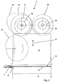
- FIG. 2 shows a preferred embodiment of the invention of the punching device 2 of the punching and embossing machine 1.
- the punching device 2 consists of a stationary under table 9 provided with a counter plate 15 and an up and down movable top table 10 provided with a punch knife 16.
- the sheet 6 is held in the punch station 2 by means of a gripper bar 8 between the counter plate 15 and the punch knife 16.
- the upper table 10 is moved perpendicular to the lower table 9 in the direction of the arrow 17.
- the upper table 10 is held under tension by spring force in the direction of the eccentric shafts 18, 19.
- the eccentric shafts 18, 19 have eccentric receptacles on which pressure rollers 20, 21 are rotatably mounted.
- the eccentric shafts are driven by gears 22, 23 which are firmly connected to the eccentric shafts 18, 19.
- a non-circular gear wheel 24 is firmly connected to an eccentric shaft 19.
- the non-uniformly acting gear of the drive of the eccentric shafts 18, 19 in the illustrated embodiment consists of the two non-circular gears 24, 25.
- a drive for example an electric motor, can then be connected directly to the non-circular gear 25.
- the embodiment of the eccentric shaft drive shown here represents the preferred embodiment of the invention. However, it is also conceivable to connect a further transmission or an indirect drive such as a belt transmission or a linkage to the non-uniform transmission 24, 25. From the uniform movement of the driving non-circular gear 25, a non-uniform movement is transmitted to the eccentric shaft 19 with the aid of the non-circular gear 24. Via the gear 23, the non-uniform movement is transmitted to the gear 22 and thus to the eccentric shaft 18, so that the two eccentric shafts 18, 19 move synchronously and move the upper table 10 in the direction of the lower table 9 in parallel. The rotary movement of the eccentric shafts 18, 19 is synchronous, but in opposite directions.
- the non-uniformly acting gear consists of a cam gear which drives the eccentric shafts 18, 19 non-uniformly.
- the cam mechanism is mounted in the machine frame 5 and can be driven directly via an electric motor or indirectly, for example via a belt transmission, a linkage or comparable drives.
- the eccentric shafts 18, 19 move the upper table 10 in the direction of arrow 17 and against the spring force onto the sheet 6 to be punched. After punching, the upper table moves again in the direction of the eccentric shafts 18, 19 and a new sheet 6 can be placed between the upper table 10 and the under table 9 are moved.
- the time course of the lifting movement of the upper table 10 is shown in FIG. 3.
- FIG. 3 shows a diagram in which the lifting movement of the upper table 10 is plotted as a dashed line as a function of the angular degree of the eccentric shafts.
- the position 0 ° describes the bottom dead center UT of the upper table 10, the position OT the top dead center of the movement of the top table 10 and the position 360 ° the next bottom dead center UT of the top table 10 as the next stamping and / or embossing step.
- the dashed line of movement of the lifting table shows an almost sinusoidal course of a conventional eccentric shaft drive for an upper table 10.
- the gripper bar stands still. It is in the rest R.
- the gripper bar 8 is accelerated until the time OT.
- the acceleration time of the gripper bar is marked with BG.
- the gripper bar is also decelerated VG until it comes to a standstill.
- the rest period R follows.
- the upper table 10 To move the gripper bar 8, the upper table 10 must have a certain minimum stroke Hmin. exhibit. This minimum stroke Hmin results in a time window ZF during which the gripper bar 8 must have moved the sheet 6 out between the upper table 10 and the lower table 9 and reinserted it. Outside of this time ZF, only small acceleration and deceleration phases of the gripper bar 8 can lie.
- the acceleration phase of the upper table 10 from bottom dead center UT is almost identical to the deceleration phase before top dead center OT.
- a shift in the time window ZF can only be achieved by a shift in the time window means for example a steeper increase in the movement curve of the upper table 10. Due to the steeper increase in the movement curve of the upper table 10, the time window ZF can be shifted towards an earlier start. This results in Shorter rest times R of the gripper bar 8 and thus shorter cycle times for punching sheets 6.
- the dash-dotted line is intended to illustrate the steeper acceleration of the upper table 10.
- the cycle times for the acceleration BG and the deceleration VG of the gripper bar are physically bound to limits. Above a certain acceleration, the gripper bar 8 can no longer safely guide the sheet 6, so that the time window is only slightly variable.
- the use of a non-uniform gear for driving the eccentric shafts 18, 19 causes the upper table 10 to accelerate more, so that on the one hand the time window ZF can be increased or the rest time R can be reduced.
- the rest time R is reduced, so that the cycle time in the punching station 2 of the punching and embossing machine is shortened.
- a reduction in the rest time R from 90 ° to 70 ° can be specified, which corresponds to a reduction in the cycle time by approximately 5 to 6%.
- the dash-dotted line clearly shows that the time window required for the movement of the gripper bar can be shifted by the steeper increase in the acceleration curve of the upper table 10.
- the time window for moving the gripper bar is predetermined by the physical limits. The time saved by the steeper increase in the movement curve of the upper table 10 can thus be used to reduce the cycle time of the punching station 2.
Landscapes
- Engineering & Computer Science (AREA)
- Mechanical Engineering (AREA)
- Life Sciences & Earth Sciences (AREA)
- Forests & Forestry (AREA)
- Perforating, Stamping-Out Or Severing By Means Other Than Cutting (AREA)
Abstract
Description
Die Erfindung betrifft eine Bogenstanz- und -prägemaschine mit einem mit einer Gegenplatte versehenen ruhenden Tisch und einem mit einem Stanzmesser versehenen über einen Hubantrieb senkrecht zur Gegenplatte auf- und abbeweglichen Tisch, wobei der Hubantrieb aus mindestens einer im Maschinengestell gelagerten Exzenterwelle besteht und eine Exzenterwelle mit exzentrisch gelagerten Andruckrollen aufweist.The invention relates to a sheet punching and embossing machine with a stationary table provided with a counter plate and a table provided with a punch knife which can be moved up and down via a lifting drive perpendicular to the counter plate, the lifting drive consisting of at least one eccentric shaft mounted in the machine frame and an eccentric shaft with has eccentrically mounted pressure rollers.
Ein gattungsgemäßer Antrieb für eine Bogenstanz- und -prägemaschine ist aus der DE 30 44 083 C3 bekannt. Die hierin beschriebene Maschine besitzt einen festen Untertisch und einen auf- und abbeweglichen Obertisch zum Stanzen von Bögen aus Papier, Pappe und dergleichen. Die Bewegung des auf- und abbeweglichen Obertisches wird über Rollen realisiert, die auf zwei über dem Tisch angeordneten Exzenterwellen angeordnet sind. Der Obertisch liegt mit Federkraft gegen die Rollen auf der Exzenterwelle an. Durch eine Drehbewegung der Exzenterwellen wird der Obertisch senkrecht gegen den Untertisch bewegt. Durch den Exzenterantrieb ergibt sich im zeitlichen Verlauf eine im wesentlichen sinusförmige Hubbewegung des Obertisches.A generic drive for a sheet punching and embossing machine is known from DE 30 44 083 C3. The machine described herein has a fixed lower table and a movable upper and lower table for punching sheets of paper, cardboard and the like. The movement of the up and down movable upper table is realized by rollers, which are arranged on two eccentric shafts arranged above the table. The upper table rests against the rollers on the eccentric shaft with spring force. The upper table is moved vertically against the lower table by rotating the eccentric shafts. The eccentric drive results in an essentially sinusoidal lifting movement of the upper table over time.
Die Bögen werden in der Bogenstanz- und -prägemaschine von auf umlaufenden Ketten befestigten Greiferstangenanordnungen an ihrer Vorderkante ergriffen und dann intermittierend durch die Stanz- und Prägeeinrichtung und weitere Stationen hindurchgezogen. Während der Hubbewegung des Obertisches muß der gestanzte Bogen aus dem Stanztisch herausbewegt und der neue Bogen eingeführt werden. Die Sinuskurve des zeitlichen Verlaufs der Hubbewegung öffnet dabei ein immer gleichbleibend großes zeitliches Fenster, das natürlich abhängig von der Drehgeschwindigkeit der Exzenterwellen ist. Beschränkt wird diese Zeit durch den minimalen Hub des Obertisches, den die Greiferstangen für den Durchlauf unterhalb des Obertisches benötigen. Die Bewegungsund Rastzeiten der Greiferstangen sind somit festgelegt. Die Zykluszeiten der Maschine können aber über die Drehgeschwindigkeit der Exzenterwellen variiert werden. Hierbei legen aber physikalische Grenzen, wie zum Beispiel die Beschleunigung der Bögen, die maximale Anzahl der Maschinenzyklen und damit die Arbeitsgeschwindigkeit der Bogenstanz- und -prägemaschine fest. Die Zeit zum Beschleunigen und Verzögern der Greiferstangen läßt sich daher zur Erhöhung der Arbeitsgeschwindigkeit nicht mehr verkürzen.The sheets are gripped in the sheet punching and embossing machine by gripper bar arrangements attached to circulating chains at their front edge and then intermittently pulled through the punching and embossing device and further stations. During the lifting movement of the upper table, the punched sheet must be moved out of the punching table and the new sheet inserted. The sine curve of the time course of the stroke movement opens a constantly large time window, which of course depends on the rotational speed of the eccentric shafts. This time is limited by the minimal stroke of the upper table, which the gripper bars require for the passage below the upper table. The movement and rest times of the gripper bars are thus fixed. The cycle times of the machine can be varied via the rotational speed of the eccentric shafts. Here, however, physical limits, such as the acceleration of the sheets, the maximum number of machine cycles and thus the working speed of the sheet punching and embossing machine. The time to accelerate and decelerate Gripper bars can therefore no longer be shortened to increase the working speed.
Ein weiterer gattungsgemäßer Antrieb wird in dem amerikanischen Patent US 4,767,393 beschrieben. Die beschriebene Stanz- und Prägemaschine besitzt einen angetriebenen Ober- und Untertisch. Der Antrieb erfolgt dabei über exzentrisch an einer Welle angeordnete Scheiben, die unmittelbar auf den Ober- und Untertisch wirken. Durch eine Drehbewegung der Wellen wird über die exzentrischen Scheiben eine gleichförmige Bewegung des Ober- und Untertisches zueinander erzielt.Another generic drive is described in the American patent US 4,767,393. The punching and embossing machine described has a driven upper and lower table. The drive takes place via eccentrically arranged disks on a shaft, which act directly on the upper and lower table. By rotating the shafts, a uniform movement of the upper and lower table towards each other is achieved via the eccentric discs.
Der Erfindung liegt die Aufgabe zugrunde, einen Antrieb für eine Stanz- und Prägestation einer Bogenstanz- und -prägemaschine zu schaffen, die auf einfache konstruktive Weise eine Erhöhung der Arbeitsgeschwindigkeit der Maschine ermöglicht.The invention has for its object to provide a drive for a punching and embossing station of a sheet punching and embossing machine, which allows a simple constructional increase in the working speed of the machine.
Diese Aufgabe wird entsprechend dem Patentanspruch 1 dadurch gelöst, der Antrieb der Exzenterwellen über ein ungleichförmig wirkendes Getriebe erfolgt, so daß eine ungleichförmige Bewegung des bewegten Tisches ermöglicht ist. Durch die Ausbildung eines ungleichförmigen Antriebs für die Exzenterwellen ist nun eine Möglichkeit geschaffen, den zeitlichen Verlauf der Beschleunigung und Verzögerung der Hubbewegung des bewegbaren Tisches beliebig zu beeinflussen und so die Arbeitsgeschwindigkeit der Maschine zu erhöhen.This object is achieved according to
Dazu wird lediglich ein ungleichförmig wirkendes Getriebe als Antrieb für die Exzenterwellen eingesetzt, was wiederum mit minimalem Kostenaufwand und geringstem konstruktivem Aufwand möglich ist.For this purpose, only a non-uniformly acting gear is used as a drive for the eccentric shafts, which in turn is possible with minimal cost and the least design effort.
In den Zeichnungen ist eine bevorzugte Ausführungsform eines Antriebs der Exzenterwellen einer Bogenstanz- und -prägemaschine dargestellt.In the drawings, a preferred embodiment of a drive for the eccentric shafts of a sheet punching and embossing machine is shown.
Es zeigt
Figur 1- den prinzipiellen Aufbau einer Bogenstanz- und -prägemaschine,
Figur 2- die Seitenansicht auf eine Bogenstanz- und -prägestation einer Bogenstanz- und -prägemaschine und
Figur 3- eine graphische Darstellung der Hubbewegung des Obertisches in Abhängigkeit der Drehbewegung der Exzenterwellen aufgetragen in Winkelgrad.
- Figure 1
- the basic structure of a sheet punching and embossing machine,
- Figure 2
- the side view of a sheet punching and embossing station of a sheet punching and embossing machine and
- Figure 3
- a graphical representation of the lifting movement of the upper table as a function of the rotary movement of the eccentric shafts plotted in degrees.
In Figur 1 ist der prinzipielle Aufbau einer Bogenstanz- und -prägemaschine 1 zum Stanzen, Ausbrechen und Ablegen von Bögen aus Papier, Pappe und dergleichen dargestellt. Die Stanz- und Prägemaschine 1 besteht aus einer Stanzeinrichtung 2, einer Ausbrecheinrichtung 3 und einer Ablegeeinrichtung 4, die von einem gemeinsamen Maschinengehäuse 5 getragen und umschlossen werden.In Figure 1, the basic structure of a sheet punching and
Die Bögen 6 werden von auf umlaufenden Ketten 7 befestigten Greiferstangen 8 an ihrer Vorderkante ergriffen und intermittierend durch die verschiedenen Stationen 2, 3 und 4 der Stanz- und Prägemaschine 1 hindurchgezogen.The
Die Stanzstation 2 besteht aus einem Untertisch 9 und einem Obertisch 10. Der Untertisch 9 ist fest im Maschinengestell gelagert und mit einer Gegenplatte zum Stanzmesser versehen. Der Obertisch 10 ist auf- und abbewegbar gelagert und über eine im weiteren näher beschriebene Antriebsvorrichtung antreibbar.The
Die Greiferstange 8 transportiert den Bogen 6 von der Stanz- und Prägestation 2 in die nachfolgende Ausbrechstation 3, die mit Ausbrechwerkzeugen ausgestattet sein kann. ln der Ausbrechstation 3 werden mit Hilfe der Ausbrechwerkzeuge die nicht benötigten Abfallstücke aus dem Bogen nach unten herausgestoßen, wodurch diese Abfallstücke 11 in einen unter der Station eingeschobenen behälterartigen Wagen 12 fallen.The
Von der Ausbrechstation 3 gelangt der Bogen 6 in die Ablegestation 4, wo der Bogen entweder nur einfach abgelegt wird, oder aber günstiger gleichzeitig eine Trennung der einzelnen Nutzen erfolgt. Die Ablegestation 4 kann auch eine Palette 13 enthalten, auf der die einzelnen Bögen in Form eines Stapels 14 aufgestapelt werden, so daß nach Erreichen einer bestimmten Stapelhöhe die Paletten mit den aufgestapelten Bögen 14 aus dem Bereich der Stanz- und Prägemaschine 1 weggefahren werden können.From the
Wie zu erkennen ist, tragen die Ketten 7 mehrere Greiferstangen 8, beispielsweise sind es hier acht, so daß mehrere Bögen 6 gleichzeitig in den verschiedenen Stationen 2, 3 und 4 bearbeitet werden können.As can be seen, the
In Figur 2 ist eine bevorzugte Ausführungsform der Erfindung der Stanzeinrichtung 2 der Stanz- und Prägemaschine 1 näher dargestellt. Die Stanzeinrichtung 2 besteht aus einem mit einer Gegenplatte 15 versehenen ruhenden Untertisch 9 und einem mit einem Stanzmesser 16 versehenen auf- und abbeweglichen Obertisch 10. Zwischen der Gegenplatte 15 und dem Stanzmesser 16 wird der Bogen 6 mittels einer Greiferstange 8 in der Stanzstation 2 gehalten. Zum Positionieren des Bogens 6 in der Stanzstation 2 mittels des Greiferwagens 8 wird der Obertisch 10 in Richtung des Pfeils 17 senkrecht zum Untertisch 9 verfahren. Der Obertisch 10 wird mittels Federkraft in Richtung der Exzenterwellen 18, 19 unter Spannung gehalten.FIG. 2 shows a preferred embodiment of the invention of the
Die Exzenterwellen 18, 19 besitzen exzentrische Aufnahmen auf denen Andruckrollen 20, 21 drehbar gelagert befestigt sind. Der Antrieb der Exzenterwellen erfolgt über fest mit den Exzenterwellen 18, 19 verbundene Zahnräder 22, 23. Zur Erzielung eines ungleichförmigen Antriebs der Exzenterwellen 18, 19 ist mit einer Exzenterwelle 19 ein Unrund-Zahnrad 24 fest verbunden. Das ungleichförmig wirkende Getriebe des Antriebs der Exzenterwellen 18, 19 besteht in dem dargestellten Ausführungsbeispiel aus den beiden Unrund-Zahnrädern 24, 25. An das Unrund-Zahnrad 25 kann dann ein Antrieb, zum Beispiel ein elektrischer Motor, unmittelbar angeschlossen werden.The
Die hier dargestellte Ausführungsform des Antriebs der Exzenterwellen stellt die bevorzugte Ausführungsform der Erfindung dar. Es ist aber ebenfalls vorstellbar, an das ungleichförmige Getriebe 24, 25 ein weiteres Getriebe oder einen mittelbaren Antrieb wie zum Beispiel ein Riemengetriebe oder ein Gestänge anzuschließen. Aus der gleichförmigen Bewegung des antreibenden Unrund-Zahnrads 25 wird eine ungleichförmige Bewegung an die Exzenterwelle 19 mit Hilfe des Unrund-Zahnrads 24 übertragen. Über das Zahnrad 23 wird die ungleichförmige Bewegung an das Zahnrad 22 und damit an die Exzenterwelle 18 übertragen, so daß sich die beiden Exzenterwellen 18, 19 synchron bewegen und den Obertisch 10 parallel in Richtung des Untertisches 9 bewegen. Die Drehbewegung der Exzenterwellen 18, 19 ist synchron, aber gegenläufig.The embodiment of the eccentric shaft drive shown here represents the preferred embodiment of the invention. However, it is also conceivable to connect a further transmission or an indirect drive such as a belt transmission or a linkage to the
In einer weiteren Ausgestaltungsvariante der Erfindung besteht das ungleichförmig wirkende Getriebe aus einem Kurvengetriebe, das die Exzenterwellen 18, 19 ungleichförmig antreibt. Das Kurvengetriebe ist im Maschinengestell 5 gelagert und kann unmittelbar über einen elektrischen Motor oder mittelbar, zum Beispiel über ein Riemengetriebe, ein Gestänge oder vergleichbare Antriebe angetrieben sein.In a further embodiment variant of the invention, the non-uniformly acting gear consists of a cam gear which drives the
Die Exzenterwellen 18, 19 bewegen den Obertisch 10 in Richtung des Pfeils 17 und gegen die Federkraft auf den zu stanzenden Bogen 6. Nach dem Stanzen verfährt der Obertisch wieder in Richtung der Exzenterwellen 18, 19 und ein neuer Bogen 6 kann zwischen den Obertisch 10 und den Untertisch 9 bewegt werden. Der zeitliche Verlauf der Hubbewegung des Obertisches 10 ist in Figur 3 wiedergegeben.The
Die Figur 3 zeigt ein Diagramm, in dem die Hubbewegung des Obertisches 10 als gestrichtelte Linie in Abhängigkeit des Winkelgrads der Exzenterwellen aufgetragen ist. Die Position 0° beschreibt den unteren Totpunkt UT des Obertisches 10, die Position OT den oberen Totpunkt der Bewegung des Obertisches 10 und die Position 360° den nächsten unteren Totpunkt UT des Obertisches 10 als nächsten Stanz- und/oder Prägeschritt.FIG. 3 shows a diagram in which the lifting movement of the upper table 10 is plotted as a dashed line as a function of the angular degree of the eccentric shafts. The position 0 ° describes the bottom dead center UT of the upper table 10, the position OT the top dead center of the movement of the top table 10 and the position 360 ° the next bottom dead center UT of the top table 10 as the next stamping and / or embossing step.
Über der gestrichelten Bewegungslinie des Hubtisches sind die Bewegungen der Greiferstange 8 mit dem daran befindlichen Bogen 6 dargestellt. Die gestrichelte Linie zeigt einen nahezu sinusförmigen Verlauf eines herkömmlichen Exzenterwellenantriebs für einen Obertisch 10. Von 0° ausgehend steht die Greiferstange still. Sie befindet sich in der Rast R. Anschließend wird die Greiferstange 8 beschleunigt bis zum Zeitpunkt OT. Die Beschleunigungszeit der Greiferstange ist mit BG gekennzeichnet. Etwa am oberen Totpunkt, das heißt am Wendepunkt des Obertisches 10 wird auch die Greiferstange verzögert VG, bis daß sie zum Stillstand kommt. Es folgt die weitere Rastzeit R.Above the dashed line of movement of the lifting table, the movements of the
Zum Verfahren der Greiferstange 8 muß der Obertisch 10 einen gewissen minimalen Hub Hmin. aufweisen. Aus diesem minimalen Hub Hmin ergibt sich ein Zeitfenster ZF, während dem die Greiferstange 8 den Bogen 6 zwischen dem Obertisch 10 und dem Untertisch 9 herausbewegt und wieder eingeführt haben muß. Außerhalb dieser Zeit ZF können lediglich kleine Beschleunigungs- und Verzögerungsphasen der Greiferstange 8 liegen. Die Beschleunigungsphase des Obertischs 10 vom unteren Totpunkt UT an ist nahezu identisch mit der Verzögerungsphase vor dem oberen Totpunkt OT. Da das Verfahren der Greiferstange 8 aber erst nach dem Erreichen der Höhe Hmin erfolgen kann und die Beschleunigungs- und Verzögerungsphasen des Greiferwagens BG, VG aus physikalischen Gründen nicht weiter verkürzt werden können, kann eine Verschiebung des Zeitfensters ZF nur über eine Verschiebung des Zeitfensters, dass heißt zum Beispiel einen steileren Anstieg der Bewegungskurve des Obertisches 10 erfolgen. Durch den steileren Anstieg der Bewegungskurve des Obertisches 10 kann eine Verschiebung des Zeitfensters ZF hin zu einem zeitlich früheren Beginn erfolgen. Hieraus ergeben sich kürzere Rastzeiten R der Greiferstange 8 und somit kürzere Zykluszeiten zum Stanzen von Bögen 6. Die strichpunktierte Linie soll den steileren Verlauf der Beschleunigung des Obertisches 10 verdeutlichen.To move the
Die Zykluszeiten für die Beschleunigung BG und die Verzögerung VG der Greiferstange sind physikalisch an Grenzen gebunden. Über einer gewissen Beschleunigung kann die Greiferstange 8 den Bogen 6 nicht mehr sicher führen, so daß das Zeitfenster nur geringfügig variabel ist. Der Einsatz eines ungleichförmigen Getriebes zum Antrieb der Exzenterwellen 18, 19 bewirkt aber eine größere Beschleunigung des Obertisches 10, so daß einerseits das Zeitfenster ZF vergrößert oder die Rastzeit R verkleinert werden können. In der bevorzugten Ausführungsform der Erfindung wird die Rastzeit R verkleinert, so daß sich die Zykluszeit in der Stanzstation 2 der Stanz- und Prägemaschine verkürzt. In absoluten Werten kann hier von einer Reduzierung der Rastzeit R von 90° auf 70° angegeben werden, was einer Reduzierung der Zykluszeit um etwa 5 bis 6% entspricht.The cycle times for the acceleration BG and the deceleration VG of the gripper bar are physically bound to limits. Above a certain acceleration, the
Die strichpunktierte Linie zeigt deutlich, daß durch den steileren Anstieg der Beschleunigungskurve des Obertisches 10 das für die Bewegung der Greiferstange benötigte Zeitfenster verschoben werden kann. Das Zeitfenster zur Bewegung der Greiferstange ist durch die physikalischen Grenzen vorbestimmt. Der Zeitgewinn durch den steileren Anstieg der Bewegungskurve des Obertisches 10 kann somit zur Verringerung der Zykluszeit der Stanzstation 2 verwendet werden.The dash-dotted line clearly shows that the time window required for the movement of the gripper bar can be shifted by the steeper increase in the acceleration curve of the upper table 10. The time window for moving the gripper bar is predetermined by the physical limits. The time saved by the steeper increase in the movement curve of the upper table 10 can thus be used to reduce the cycle time of the punching
Claims (5)
Applications Claiming Priority (2)
| Application Number | Priority Date | Filing Date | Title |
|---|---|---|---|
| DE10244585A DE10244585A1 (en) | 2002-09-25 | 2002-09-25 | Sheet punching and embossing machine |
| DE10244585 | 2002-09-25 |
Publications (2)
| Publication Number | Publication Date |
|---|---|
| EP1403013A2 true EP1403013A2 (en) | 2004-03-31 |
| EP1403013A3 EP1403013A3 (en) | 2005-02-09 |
Family
ID=31969552
Family Applications (1)
| Application Number | Title | Priority Date | Filing Date |
|---|---|---|---|
| EP03018703A Withdrawn EP1403013A3 (en) | 2002-09-25 | 2003-08-25 | Sheet embossing and die-cutting machine |
Country Status (3)
| Country | Link |
|---|---|
| US (1) | US20040055481A1 (en) |
| EP (1) | EP1403013A3 (en) |
| DE (1) | DE10244585A1 (en) |
Cited By (1)
| Publication number | Priority date | Publication date | Assignee | Title |
|---|---|---|---|---|
| CN111347768A (en) * | 2020-04-14 | 2020-06-30 | 无锡城市职业技术学院 | Continuous quick mechatronic cross cutting lithography apparatus |
Families Citing this family (5)
| Publication number | Priority date | Publication date | Assignee | Title |
|---|---|---|---|---|
| US20060043036A1 (en) * | 2004-08-30 | 2006-03-02 | Robertson James D | Cooler door shelf device with removable product panel |
| US7080744B2 (en) * | 2004-09-22 | 2006-07-25 | Display Industries, Llc. | Vented cooler door shelf device |
| DE102007009670A1 (en) | 2007-02-28 | 2008-09-04 | Norbert Quenzel | Punching and embossing machine for producing blanks from paper and cardboard sheets comprises grooves having a rectangular cross-section arranged in the guide rails in the region of chain and guiding strips |
| DE102007012640A1 (en) * | 2007-03-16 | 2008-09-18 | Heidelberger Druckmaschinen Ag | Sheet punching and embossing machine |
| CN116329228B (en) * | 2023-05-29 | 2023-09-08 | 合肥亿昌兴精密机械有限公司 | Anti-accumulation calendaring material receiving device and receiving method |
Citations (1)
| Publication number | Priority date | Publication date | Assignee | Title |
|---|---|---|---|---|
| DE19601300A1 (en) * | 1996-01-16 | 1997-07-17 | Vdw Ev | Drive device for a forming machine |
Family Cites Families (13)
| Publication number | Priority date | Publication date | Assignee | Title |
|---|---|---|---|---|
| CH560599A5 (en) * | 1972-02-01 | 1975-04-15 | Madag Maschinen Apparatebau | |
| GB1454516A (en) * | 1973-11-05 | 1976-11-03 | Schroter F | Process and apparatus for punching or embossing sheets or webs of paper cardboard or similar materal |
| DE3044084C2 (en) * | 1980-11-24 | 1985-09-26 | Bobst S.A., Lausanne | Gripper device for sheet processing machines |
| DE8031208U1 (en) * | 1980-11-24 | 1990-07-12 | Bobst S.A., Lausanne, Ch | |
| DE3044083C2 (en) * | 1980-11-24 | 1990-05-10 | Bobst S.A., Lausanne | Punching devices for automatic punching machines for punching sheets of paper, cardboard and the like. |
| US4767393A (en) * | 1983-07-22 | 1988-08-30 | Smith Edwin K | High speed platen-type die cutter |
| US4662234A (en) * | 1985-10-25 | 1987-05-05 | Tamagawa Machinery Co., Ltd. | Driving apparatus for powder compacting press |
| DE4129029A1 (en) * | 1991-08-31 | 1993-03-04 | Blohm Voss Ag | Flat bed stamping press for paper sheet - has single crankshaft on side of machine driving table up and down through multiplicity of horizontally reciprocated wedges. |
| DE4218955C2 (en) * | 1992-06-10 | 1998-02-26 | Hasenclever Maschf Sms | Drive for an eccentric shaft of an eccentric forging press |
| US5611246A (en) * | 1993-08-20 | 1997-03-18 | Eastman Kodak Company | Variable angular velocity coupling for reciprocating devices |
| JPH0966500A (en) * | 1995-09-01 | 1997-03-11 | Sanwa Seisaku Kk | Automatic plate puncher |
| US5692986A (en) * | 1995-12-14 | 1997-12-02 | Eastman Kodak Company | Variable dwell cycloidal indexing device |
| US20030150315A1 (en) * | 2002-02-11 | 2003-08-14 | Li-Chen Lin | Cam gear punch |
-
2002
- 2002-09-25 DE DE10244585A patent/DE10244585A1/en not_active Withdrawn
-
2003
- 2003-08-25 EP EP03018703A patent/EP1403013A3/en not_active Withdrawn
- 2003-09-25 US US10/670,661 patent/US20040055481A1/en not_active Abandoned
Patent Citations (1)
| Publication number | Priority date | Publication date | Assignee | Title |
|---|---|---|---|---|
| DE19601300A1 (en) * | 1996-01-16 | 1997-07-17 | Vdw Ev | Drive device for a forming machine |
Cited By (2)
| Publication number | Priority date | Publication date | Assignee | Title |
|---|---|---|---|---|
| CN111347768A (en) * | 2020-04-14 | 2020-06-30 | 无锡城市职业技术学院 | Continuous quick mechatronic cross cutting lithography apparatus |
| CN111347768B (en) * | 2020-04-14 | 2022-05-03 | 无锡城市职业技术学院 | Continuous quick mechatronic cross cutting lithography apparatus |
Also Published As
| Publication number | Publication date |
|---|---|
| US20040055481A1 (en) | 2004-03-25 |
| DE10244585A1 (en) | 2004-04-15 |
| EP1403013A3 (en) | 2005-02-09 |
Similar Documents
| Publication | Publication Date | Title |
|---|---|---|
| CH653945A5 (en) | PUNCHING DEVICE. | |
| DE3515112A1 (en) | PUNCHING MACHINE | |
| EP2452790A1 (en) | Processing station for a stamping machine and method for removing a test blank | |
| DE102007012638A1 (en) | Sheet punching and embossing machine | |
| DE3513703C2 (en) | ||
| DE2245515C3 (en) | Stacking device for placing and discharging stacks of bags | |
| DE1611617A1 (en) | Device for stripping off stamping residues | |
| EP1403013A2 (en) | Sheet embossing and die-cutting machine | |
| DE102008011051A1 (en) | Sheet e.g. paper sheet, punching and embossing machine, has cam gear comprising cam disks, cam rollers and shafts, where driven cam disks roll on cam rollers that are fastened to movable platen | |
| EP1760022A1 (en) | Cylinder for shaping flat material | |
| CH712241A2 (en) | Method and apparatus for ejecting punched lids or labels into a stacking channel. | |
| DE3213233C2 (en) | Embossing machine for embossing characters in workpieces | |
| DE2744061A1 (en) | DEVICE FOR THE AUTOMATIC STACKING OF STRIPS WHICH LEAVE THE MACHINE FOR THE PRODUCTION OF THE SAME | |
| DE102007012640A1 (en) | Sheet punching and embossing machine | |
| DE2009138C3 (en) | Device for the continuous removal of workpieces | |
| DE1940227A1 (en) | Transport device | |
| DE60200505T2 (en) | Sheet feeder for cardboard sheets | |
| EP2719508A1 (en) | Drive device and punching machine with such a drive device | |
| DE2446722A1 (en) | DEVICE FOR CUTTING A CONTINUOUSLY MOVING WEB | |
| EP0185146B1 (en) | Stacking device for plat products made from paper, cellulose cotton or suchlike | |
| DE102012207320B4 (en) | Suction conveyor and method of removing a sheet from a stack of sheets | |
| EP0799781A2 (en) | Device for stacking plates | |
| EP0972585A2 (en) | Rotary forming machine with better forming behaviour | |
| AT270344B (en) | Method and device for punching rotor and stator sheets for electric motors, preferably with conical rotors and stators | |
| DE3425193A1 (en) | HIGH PERFORMANCE PUNCHING MACHINE |
Legal Events
| Date | Code | Title | Description |
|---|---|---|---|
| PUAI | Public reference made under article 153(3) epc to a published international application that has entered the european phase |
Free format text: ORIGINAL CODE: 0009012 |
|
| AK | Designated contracting states |
Kind code of ref document: A2 Designated state(s): AT BE BG CH CY CZ DE DK EE ES FI FR GB GR HU IE IT LI LU MC NL PT RO SE SI SK TR |
|
| AX | Request for extension of the european patent |
Extension state: AL LT LV MK |
|
| RIN1 | Information on inventor provided before grant (corrected) |
Inventor name: NAMOWITZ, HERMANN Inventor name: KLAASSEN, GERHARD |
|
| PUAL | Search report despatched |
Free format text: ORIGINAL CODE: 0009013 |
|
| AK | Designated contracting states |
Kind code of ref document: A3 Designated state(s): AT BE BG CH CY CZ DE DK EE ES FI FR GB GR HU IE IT LI LU MC NL PT RO SE SI SK TR |
|
| AX | Request for extension of the european patent |
Extension state: AL LT LV MK |
|
| RIC1 | Information provided on ipc code assigned before grant |
Ipc: 7B 26D 5/22 B Ipc: 7B 31B 1/20 B Ipc: 7B 30B 1/26 B Ipc: 7B 26D 5/16 B Ipc: 7B 26D 5/14 B Ipc: 7B 26D 5/08 A |
|
| 17P | Request for examination filed |
Effective date: 20050809 |
|
| AKX | Designation fees paid |
Designated state(s): AT BE BG CH CY CZ DE DK EE ES FI FR GB GR HU IE IT LI LU MC NL PT RO SE SI SK TR |
|
| 17Q | First examination report despatched |
Effective date: 20070115 |
|
| STAA | Information on the status of an ep patent application or granted ep patent |
Free format text: STATUS: THE APPLICATION IS DEEMED TO BE WITHDRAWN |
|
| 18D | Application deemed to be withdrawn |
Effective date: 20110329 |