EP1402684B1 - Network documentation system with electronic modules - Google Patents
Network documentation system with electronic modules Download PDFInfo
- Publication number
- EP1402684B1 EP1402684B1 EP02723184A EP02723184A EP1402684B1 EP 1402684 B1 EP1402684 B1 EP 1402684B1 EP 02723184 A EP02723184 A EP 02723184A EP 02723184 A EP02723184 A EP 02723184A EP 1402684 B1 EP1402684 B1 EP 1402684B1
- Authority
- EP
- European Patent Office
- Prior art keywords
- network
- source device
- zone
- documentation system
- electronic modules
- Prior art date
- Legal status (The legal status is an assumption and is not a legal conclusion. Google has not performed a legal analysis and makes no representation as to the accuracy of the status listed.)
- Expired - Lifetime
Links
- 238000004891 communication Methods 0.000 claims abstract description 22
- 230000004044 response Effects 0.000 claims abstract description 12
- 230000005540 biological transmission Effects 0.000 claims 1
- 238000012360 testing method Methods 0.000 description 19
- 238000007792 addition Methods 0.000 description 6
- 238000000034 method Methods 0.000 description 6
- 238000012546 transfer Methods 0.000 description 6
- 230000008901 benefit Effects 0.000 description 4
- 230000002452 interceptive effect Effects 0.000 description 3
- 230000008569 process Effects 0.000 description 3
- 239000004020 conductor Substances 0.000 description 2
- 239000000835 fiber Substances 0.000 description 2
- 230000037361 pathway Effects 0.000 description 2
- 230000032683 aging Effects 0.000 description 1
- 238000012790 confirmation Methods 0.000 description 1
- 238000001514 detection method Methods 0.000 description 1
- 238000005516 engineering process Methods 0.000 description 1
- 230000007717 exclusion Effects 0.000 description 1
- 238000003780 insertion Methods 0.000 description 1
- 230000037431 insertion Effects 0.000 description 1
- 238000007726 management method Methods 0.000 description 1
- 230000007246 mechanism Effects 0.000 description 1
Images
Classifications
-
- H—ELECTRICITY
- H04—ELECTRIC COMMUNICATION TECHNIQUE
- H04L—TRANSMISSION OF DIGITAL INFORMATION, e.g. TELEGRAPHIC COMMUNICATION
- H04L63/00—Network architectures or network communication protocols for network security
- H04L63/18—Network architectures or network communication protocols for network security using different networks or channels, e.g. using out of band channels
Definitions
- LAN local area network
- EP 0 602 787 discloses a method and apparatus for controlling the same functions of a networked printer that can be manually selected from the front panel of the printer, but remotely through an interactive network board connectable to the printer via a bi-directional printer interface and connectable to a local area network via a local area network interface.
- a printer status request for example, from an administrator's console, is issued on the local area network and directed to the interactive network board to cause the board to interrogate the printer over the printer interface for the status of the manually selectable functions, and to transfer the status of those manually selectable functions from the board onto the local area network.
- a command to alter the status of those manually selectable functions is issued on the local area network and directed to the interactive board, the command causing the board to transfer the altered status to the printer via the printer interface, whereupon the printer status for the manually selectable functions is altered.
- US 5,915,119 discloses a network system comprising a plurality of network segments. Each of the network segments connects a plurality of user terminals that can be set in a suspend mode.
- a proxy terminal is connected to a network segment to receive requests from the router for the user terminals is not accessing in the suspend mode via the router.
- a proxy terminal is connected to a network segment to receive requests from the router for the user terminals connected to that network segment. In response to a request from the router to a destined user terminal located in that network segment, the proxy terminal wakes up the destined user terminal, thus restoring the access to the destined user terminal.
- a documentation system for a network having a source device which is connected to at least one destination device through at least one intermediate network path element.
- the source device has the capability to transmit a query signal directed to any destination device to which it is connected and each destination device has the capability to send a response signal containing its identification code back to the source device.
- the source device has the capability to transmit a query signal directed to any intermediate network path element which has a physical location in a designated zone, and an electronic module in the intennediate network path element has the capability to return a response signal containing its identification code back to the source device.
- the network documentation system utilizes software to direct the source device to sequentially send query signals directed to destination devices to which it is connected and to intermediate network path elements in each designated zone to which it is connected.
- the response signals are interpreted by the software to document the network configuration.
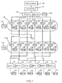
- Fig. 1 is a schematic view of a documentation system in accordance with a first embodiment of the invention.
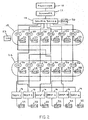
- Fig. 2 is a schematic view of a documentation system in accordance with a second embodiment of the invention.
- the invention is directed to apparatus and methods which automatically provide documentation of a network system, hereinafter called "the system".
- the system The complete disclosures of the previously filed provisional patent applications Serial Nos. 60/270,811 filed February 23, 2001 ; and 60/297,289 filed June 11, 2001 are incorporated herein by reference, as are any patent applications which they incorporate by reference.
- electronic modules are placed into electronic communication with corresponding ports or nodes of the network such that connecting apparatus, connecting the respective ports or nodes to a source device, also provide a mechanism by which query and response signals may be routed between the source device and the connected ports or nodes in the system in the same manner that data signals may be transmitted between them.
- the signals may be transmitted over the same or a different medium from the data signals (e.g., common or separate wire or fiber).
- the electronic modules have associated identification elements that may have a single component or multiple components, and the modules are capable of receiving and recognizing query signals directed to them and responding by transmitting their identification code back to the source device.
- the system may utilize signals directed toward and received from all of the respective data ports or nodes in the system and thereby formulate a "map" of the entire system as it is physically configured.
- the inventive documentation and fault detection system contemplates the preferable use of electronic modules in every final destination device within a network, as well as in every network port which connects the source device to the final destination devices.
- Each module can receive a query signal from a source, e.g., a switch, and ascertain whether the signal is directed to it by the use of address codes.
- each electronic module which is in a designated physical location zone within the system has a unique zone address code.
- the ports and their corresponding modules may be stratified into "zones" based on their relative proximity, in an electrical or communications sense, to the source device and/or the final destination device.
- every port/module within a particular zone has the same zone addressing information, however each module retains a unique identification code which is transmitted to the source device in response to a query directed to it.
- a typical network may include a pair of patch panel ports for cross-connecting between a source and one or more destinations.
- the group of patch panel ports (and the electronic modules contained therein) closer to the source from a communications standpoint i.e., the signal path direction
- the next group of ports/modules along the signal path i.e., the patch panel ports closer to the destination devices would be classified as zone 2 in this example.
- the destination devices would be classified as zone 3.
- the source sequentially sends a signal along respective output paths directed to any module along the path having a specified zone address.
- the one module in such zone along each respective path then, in turn, transmits back to the source when it receives the signal intended for its zone.
- the return signal includes the identification code of the module returning the signal.
- Such a map is useful in conducting subsequent network reconfigurations.
- Such reconfigurations may occur, for example, to switch the source device port which is connected to a particular destination device.
- Such reconfigurations can be done electronically with some source devices.
- Network reconfigurations typically entail a revisor performing a series of revisions to the cords connecting respective ports in the network. Sometimes it is necessary to install a new cord to connect two previously open ports within the network, thereby adding (“addition") a cord to the system. Other times, one needs to remove (“removal”) an already installed cord, thereby disconnecting two ports previously connected to one another. Sometimes, one end of a cord needs to be moved from one port to another (“transfer”) within the network while the other end of the cord remains in its port.
- a reconfiguration typically involves a series of instructions, i.e., additions, removals, and transfers, communicated by the system to the revisor.
- the invention may utilize a portable test plug connected to a test port including an electronic module therein referred to as a revision system module.
- the system may also include a portable screen or display such that when it is in communication with the documentation/revision system, it can communicate instructions to the revisor.
- the display may communicate an ordered sequence of cord revisions for the revisor to perform, or may simply indicate one such cord revision at a time until the revisor has performed all of the necessary steps in a reconfiguration.
- the revision system module has a unique zone address, e.g., zone 0, incorporated therein. This feature facilitates multiple independent revisors making concurrent revisions to the system, as each revision system module, is designated with a distinct zone number so that the system can readily distinguish between them.
- the revisor plugs the test plug into the LAN port closer to the source from a communication standpoint, and the system communicates whether such LAN port has been correctly found, e.g., whether a signal addressed to zone 1 along the specified path is properly acknowledged by the module associated with the test plug.
- both the test port and the LAN port include electronic modules therein capable of transmitting and receiving signals, communication between them is possible such that it can be ascertained whether the test plug has been inserted into the correct LAN port.
- the revision has correctly found the identified LAN port
- one end of the cord to be added is plugged into the found LAN port.
- the revisor then moves to the LAN port farther from the source from a communication standpoint and tests whether the second LAN port is the appropriate one by inserting the test plug. Again, the respective electronic modules communicate and, if the test plug is plugged into the correct LAN port, the other end of the cord to be added is plugged into the verified second LAN port.
- the system can confirm that the addition has been correctly completed based on communication between the source device and the electronic modules in the two LAN ports connected by the newly added cord.
- the revisor perform the addition steps in the order described, the port closer to the source and then the port farther from the source rather than in a reverse order, to enable the system to confirm proper completion of the steps by sending signals from the source device to the newly connected ports. If the reverse order were followed, a signal from the source device could not reach the farther port since the closer port would not be providing a connection between the source and the farther port.
- the revisor To perform the removal of an already installed cord in the first embodiment of the invention, the revisor likewise is provided with information identifying the two data ports from which the cord needs to be removed.
- the revisor first proceeds to the LAN port farther from the source from a communication standpoint and removes the plug from the found LAN port.
- the system can then confirm that the plug has been removed by the inability of the electronic module corresponding to that LAN port to communicate with the source device and, more specifically, for a query signal emanating from the source device to be acknowledged by the electronic module in the farther port.
- the revisor proceeds to the LAN port closer to the source from a communication standpoint and removes the cord plug inserted therein.
- test plug may then be inserted into this LAN port to verify to the revisor that he has removed the correct plug from the correct LAN port.
- revisor follow the correct order of steps relative to the two ports involved in a removal so that the system can internally ascertain correct performance of the respective steps thereof.
- a transfer can be performed in accordance with an embodiment of the invention by removing the plug on the end of the cord to be transferred from its LAN port, with the system confirming this step by the break in communication between the source device and the electronic modules of a port previously connected.
- a test plug can be used to verify that the correct LAN port at the new destination has been located. The plug just removed from the LAN port is then inserted into the new LAN port destination and the system confirms the transfer process by the ability of the source device to communicate with the electronic modules to which it is connected.
- Each electronic module in the system would require a power supply which, in various embodiments of the invention, could be provided by a pair of conductors which could also be signal pairs or a battery.
- the system could use one or more of the signal pairs to receive and transmit signals to and from particular electronic modules, including those associated with particular destination devices, sources, and network ports there between from a communications standpoint.
- a fiber optic or other LAN system could incorporate two conductors in each cable to be adapted for the same purpose.
- a computer or processor 10 is electrically connected to a scanner 12.
- the scanner may periodically or on-demand poll one or more of the data ports in the system to ascertain information about the ports. Such polling may occur on a zone-by-zone basis, with the source device sequentially sending a signal, such as a query signal, along respective output lines directed to any electronic module along the path having the specified zone address. The identified module may then return its identification code back to the source. In this manner, the entire system may effectively be mapped (i.e., documented).
- the scanner may preferably be in communication with a source device 14 and one or more destination devices 16.
- a first zone 18 of data ports 20 may preferably be congregated on a single patch panel or network rack, and each of the data ports 20 is electrically connected directly with the source device 14.
- Each of the data ports 20, identified as “DP” in the figures, has an electronic module 22, identified as “EM” in the figures, in electrical communication therewith.
- the first zone 18 of data ports includes a test port 23 disposed proximately thereto for permitting connection of a test plug.
- a second zone 24 of data ports 26 may also be congregated on another patch panel or network rack, and each of the data ports 26 is electrically connected directly with one of the destination devices 16.
- Each of the data ports 26 has an electronic module 28 in electrical communication therewith.
- the second zone 24 of data ports includes a test port 29 disposed proximately thereto for permitting connection of a test plug.
- the source device 14 preferably includes an electronic module 30 in electrical communication therewith and the destination devices 16 each include an electronic module 32 in electrical communication therewith.
- connective lines represent possible electrical connections that may be achieved by the use of patch cords and cables, and an exemplary system having six destination devices connected to a source device is shown.
- Fig. 2 illustrates an interconnect configuration wherein the first zone 18 is a patch panel and the second zone 24 are the outlet ports to which the destination devices are connected.
- the destination devices have state of the art electronic modules with common address codes and unique identification codes.
- the outlet ports are identified as "DO" in Figure 2 .
- the destination outlets while not qualitatively different than the data ports 7-12 of Figure 1 , are disposed proximately to the destination devices 16 to which they are connected. This provides the benefit of knowing approximately where a particular destination device is physically located based on its proximity to a destination outlet which is fixed in the physical world. Thus, by focusing on the identification code of the electronic module of the particular destination outlet, rather than that of the destination device itself, the approximate location of the destination device may be ascertained by the system.
- each intersection i.e., LAN port
- response signals from a particular electronic module include the identification code of the module
- pathways from a source to a destination can be more clearly identified on a link-by-link or zone-by-zone basis, and revision instructions can be more efficiently determined for a particular reconfiguration.
- Another advantage of the invention relates to facilitating multiple concurrent revisions to a single system.
- two or more test outlets for example, with distinct revision system modules having distinct identification codes in the respective test outlets, multiple users can concurrently reconfigure/revise various aspects of a particular network configuration while the system makes the appropriate confirmations for each of the test plugs connected to each of the test outlets independently.
- the present invention contemplates many embodiments not specifically described, and the explicitly described embodiments should be considered to be exemplary rather than definitional.
- the present invention may be employed in a network system having a distinct indicator, such as an LED, adjacent some or all of the LAN ports in the network. Such indicators may then be used to assist the revisor in identifying LAN ports requiring the insertion or removal of a cord plug.
Landscapes
- Engineering & Computer Science (AREA)
- Computer Hardware Design (AREA)
- Computer Security & Cryptography (AREA)
- Computing Systems (AREA)
- General Engineering & Computer Science (AREA)
- Computer Networks & Wireless Communication (AREA)
- Signal Processing (AREA)
- Small-Scale Networks (AREA)
- Data Exchanges In Wide-Area Networks (AREA)
- Two-Way Televisions, Distribution Of Moving Picture Or The Like (AREA)
- Pharmaceuticals Containing Other Organic And Inorganic Compounds (AREA)
- Information Transfer Between Computers (AREA)
Abstract
Description
- As communication network utilization and technology continues to escalate, the typical local area network (LAN) is simultaneously growing larger and denser, and it is increasingly desirable and advantageous to continuously document the physical paths of network interconnections and the physical locations of network components, including network connectors or ports in such paths and destination devices, e.g., personal computers or telephones.
- Such a documentation system provides many advantages, including facilitating the planning and revision processes, the determination of the location of the physical area of a discontinuity in the network path, and the determination of the physical locations of destination devices.
EP 0 602 787 (Canon Information Systems, Inc.) discloses a method and apparatus for controlling the same functions of a networked printer that can be manually selected from the front panel of the printer, but remotely through an interactive network board connectable to the printer via a bi-directional printer interface and connectable to a local area network via a local area network interface. A printer status request, for example, from an administrator's console, is issued on the local area network and directed to the interactive network board to cause the board to interrogate the printer over the printer interface for the status of the manually selectable functions, and to transfer the status of those manually selectable functions from the board onto the local area network. A command to alter the status of those manually selectable functions is issued on the local area network and directed to the interactive board, the command causing the board to transfer the altered status to the printer via the printer interface, whereupon the printer status for the manually selectable functions is altered.
US 5,915,119 (NCR Corporation) discloses a network system comprising a plurality of network segments. Each of the network segments connects a plurality of user terminals that can be set in a suspend mode. When a network segment is connected to the network system via a router, it is possible that the network address of a user terminal is deleted from the routing table in the router during an aging process. In this situation, the user terminal is not accessible in the suspend mode via the router. To solve this problem, a proxy terminal is connected to a network segment to receive requests from the router for the user terminals is not accessing in the suspend mode via the router. To solve this problem, a proxy terminal is connected to a network segment to receive requests from the router for the user terminals connected to that network segment. In response to a request from the router to a destined user terminal located in that network segment, the proxy terminal wakes up the destined user terminal, thus restoring the access to the destined user terminal. - There is provided a documentation system for a network having a source device which is connected to at least one destination device through at least one intermediate network path element. The source device has the capability to transmit a query signal directed to any destination device to which it is connected and each destination device has the capability to send a response signal containing its identification code back to the source device. In addition, the source device has the capability to transmit a query signal directed to any intermediate network path element which has a physical location in a designated zone, and an electronic module in the intennediate network path element has the capability to return a response signal containing its identification code back to the source device.
- The network documentation system utilizes software to direct the source device to sequentially send query signals directed to destination devices to which it is connected and to intermediate network path elements in each designated zone to which it is connected. The response signals are interpreted by the software to document the network configuration.
-
Fig. 1 is a schematic view of a documentation system in accordance with a first embodiment of the invention. -
Fig. 2 is a schematic view of a documentation system in accordance with a second embodiment of the invention. - The invention is directed to apparatus and methods which automatically provide documentation of a network system, hereinafter called "the system". The complete disclosures of the previously filed provisional patent applications Serial Nos.
60/270,811 filed February 23, 2001 60/297,289 filed June 11, 2001 - To improve the accuracy, efficiency and capability of documenting a network system, electronic modules are placed into electronic communication with corresponding ports or nodes of the network such that connecting apparatus, connecting the respective ports or nodes to a source device, also provide a mechanism by which query and response signals may be routed between the source device and the connected ports or nodes in the system in the same manner that data signals may be transmitted between them. The signals may be transmitted over the same or a different medium from the data signals (e.g., common or separate wire or fiber). The electronic modules have associated identification elements that may have a single component or multiple components, and the modules are capable of receiving and recognizing query signals directed to them and responding by transmitting their identification code back to the source device. Thus, the system may utilize signals directed toward and received from all of the respective data ports or nodes in the system and thereby formulate a "map" of the entire system as it is physically configured.
- The inventive documentation and fault detection system contemplates the preferable use of electronic modules in every final destination device within a network, as well as in every network port which connects the source device to the final destination devices. Each module can receive a query signal from a source, e.g., a switch, and ascertain whether the signal is directed to it by the use of address codes. In a preferred embodiment of the invention, each electronic module which is in a designated physical location zone within the system has a unique zone address code. In some preferable embodiments of the invention, the ports and their corresponding modules may be stratified into "zones" based on their relative proximity, in an electrical or communications sense, to the source device and/or the final destination device. In these embodiments, since each signal ultimately travels only along one path given a particular network configuration, every port/module within a particular zone has the same zone addressing information, however each module retains a unique identification code which is transmitted to the source device in response to a query directed to it.
- For example, a typical network may include a pair of patch panel ports for cross-connecting between a source and one or more destinations. In such an arrangement, the group of patch panel ports (and the electronic modules contained therein) closer to the source from a communications standpoint (i.e., the signal path direction) would be classified as
zone 1. The next group of ports/modules along the signal path (i.e., the patch panel ports closer to the destination devices would be classified aszone 2 in this example. The destination devices would be classified aszone 3. - The source sequentially sends a signal along respective output paths directed to any module along the path having a specified zone address. The one module in such zone along each respective path then, in turn, transmits back to the source when it receives the signal intended for its zone. The return signal includes the identification code of the module returning the signal. Using this procedure and information previously known to the documented system (e.g., the physical location of each port as identified by the unique identification codes thereof), the system can map (i.e. document) which ports and destination devices are connected along any particular signal path.
- As stated above, such a map is useful in conducting subsequent network reconfigurations. Such reconfigurations may occur, for example, to switch the source device port which is connected to a particular destination device. Such reconfigurations can be done electronically with some source devices. Network reconfigurations typically entail a revisor performing a series of revisions to the cords connecting respective ports in the network. Sometimes it is necessary to install a new cord to connect two previously open ports within the network, thereby adding ("addition") a cord to the system. Other times, one needs to remove ("removal") an already installed cord, thereby disconnecting two ports previously connected to one another. Sometimes, one end of a cord needs to be moved from one port to another ("transfer") within the network while the other end of the cord remains in its port. In an automatic documentation and reconfiguration management system, such as one controlled by a computer or processor as described in the references incorporated herein, a reconfiguration typically involves a series of instructions, i.e., additions, removals, and transfers, communicated by the system to the revisor.
- The invention may utilize a portable test plug connected to a test port including an electronic module therein referred to as a revision system module. The system may also include a portable screen or display such that when it is in communication with the documentation/revision system, it can communicate instructions to the revisor. For example, the display may communicate an ordered sequence of cord revisions for the revisor to perform, or may simply indicate one such cord revision at a time until the revisor has performed all of the necessary steps in a reconfiguration.
- The revision system module has a unique zone address, e.g., zone 0, incorporated therein. This feature facilitates multiple independent revisors making concurrent revisions to the system, as each revision system module, is designated with a distinct zone number so that the system can readily distinguish between them.
- In a first embodiment of the invention, during a revision or reconfiguration process, when a cord addition is required and the two LAN ports needing to be connected have been identified to the revisor, the revisor plugs the test plug into the LAN port closer to the source from a communication standpoint, and the system communicates whether such LAN port has been correctly found, e.g., whether a signal addressed to
zone 1 along the specified path is properly acknowledged by the module associated with the test plug. As both the test port and the LAN port include electronic modules therein capable of transmitting and receiving signals, communication between them is possible such that it can be ascertained whether the test plug has been inserted into the correct LAN port. If, in fact, the revision has correctly found the identified LAN port, one end of the cord to be added is plugged into the found LAN port. The revisor then moves to the LAN port farther from the source from a communication standpoint and tests whether the second LAN port is the appropriate one by inserting the test plug. Again, the respective electronic modules communicate and, if the test plug is plugged into the correct LAN port, the other end of the cord to be added is plugged into the verified second LAN port. At this point, the system can confirm that the addition has been correctly completed based on communication between the source device and the electronic modules in the two LAN ports connected by the newly added cord. It is preferable that the revisor perform the addition steps in the order described, the port closer to the source and then the port farther from the source rather than in a reverse order, to enable the system to confirm proper completion of the steps by sending signals from the source device to the newly connected ports. If the reverse order were followed, a signal from the source device could not reach the farther port since the closer port would not be providing a connection between the source and the farther port. - To perform the removal of an already installed cord in the first embodiment of the invention, the revisor likewise is provided with information identifying the two data ports from which the cord needs to be removed. The revisor first proceeds to the LAN port farther from the source from a communication standpoint and removes the plug from the found LAN port. The system can then confirm that the plug has been removed by the inability of the electronic module corresponding to that LAN port to communicate with the source device and, more specifically, for a query signal emanating from the source device to be acknowledged by the electronic module in the farther port. At this point, the revisor proceeds to the LAN port closer to the source from a communication standpoint and removes the cord plug inserted therein. The test plug may then be inserted into this LAN port to verify to the revisor that he has removed the correct plug from the correct LAN port. As with the addition, it is preferable that the revisor follow the correct order of steps relative to the two ports involved in a removal so that the system can internally ascertain correct performance of the respective steps thereof.
- A transfer can be performed in accordance with an embodiment of the invention by removing the plug on the end of the cord to be transferred from its LAN port, with the system confirming this step by the break in communication between the source device and the electronic modules of a port previously connected. A test plug can be used to verify that the correct LAN port at the new destination has been located. The plug just removed from the LAN port is then inserted into the new LAN port destination and the system confirms the transfer process by the ability of the source device to communicate with the electronic modules to which it is connected.
- Each electronic module in the system would require a power supply which, in various embodiments of the invention, could be provided by a pair of conductors which could also be signal pairs or a battery. In a network system employing twisted wire pairs for carrying signals, the system could use one or more of the signal pairs to receive and transmit signals to and from particular electronic modules, including those associated with particular destination devices, sources, and network ports there between from a communications standpoint. A fiber optic or other LAN system could incorporate two conductors in each cable to be adapted for the same purpose.
- As seen in
Fig. 1 , in a preferred embodiment of the invention, a computer orprocessor 10 is electrically connected to ascanner 12. At the direction of the processor, the scanner may periodically or on-demand poll one or more of the data ports in the system to ascertain information about the ports. Such polling may occur on a zone-by-zone basis, with the source device sequentially sending a signal, such as a query signal, along respective output lines directed to any electronic module along the path having the specified zone address. The identified module may then return its identification code back to the source. In this manner, the entire system may effectively be mapped (i.e., documented). The scanner may preferably be in communication with asource device 14 and one ormore destination devices 16. - A
first zone 18 ofdata ports 20 may preferably be congregated on a single patch panel or network rack, and each of thedata ports 20 is electrically connected directly with thesource device 14. Each of thedata ports 20, identified as "DP" in the figures, has anelectronic module 22, identified as "EM" in the figures, in electrical communication therewith. Preferably, thefirst zone 18 of data ports includes atest port 23 disposed proximately thereto for permitting connection of a test plug. Asecond zone 24 ofdata ports 26 may also be congregated on another patch panel or network rack, and each of thedata ports 26 is electrically connected directly with one of thedestination devices 16. Each of thedata ports 26 has anelectronic module 28 in electrical communication therewith. Preferably, thesecond zone 24 of data ports includes atest port 29 disposed proximately thereto for permitting connection of a test plug. Additionally, thesource device 14 preferably includes anelectronic module 30 in electrical communication therewith and thedestination devices 16 each include anelectronic module 32 in electrical communication therewith. InFig. 1 , connective lines represent possible electrical connections that may be achieved by the use of patch cords and cables, and an exemplary system having six destination devices connected to a source device is shown. -
Fig. 2 illustrates an interconnect configuration wherein thefirst zone 18 is a patch panel and thesecond zone 24 are the outlet ports to which the destination devices are connected. The destination devices have state of the art electronic modules with common address codes and unique identification codes. - The outlet ports are identified as "DO" in
Figure 2 . The destination outlets, while not qualitatively different than the data ports 7-12 ofFigure 1 , are disposed proximately to thedestination devices 16 to which they are connected. This provides the benefit of knowing approximately where a particular destination device is physically located based on its proximity to a destination outlet which is fixed in the physical world. Thus, by focusing on the identification code of the electronic module of the particular destination outlet, rather than that of the destination device itself, the approximate location of the destination device may be ascertained by the system. - Among the many benefits of the invention is the ability to completely map out a particular network configuration. In status quo systems, when a source and destination are no longer in communication, it cannot generally be easily determined which link in the pathway that connects them is the problematic link. In the present invention, each intersection, i.e., LAN port, has associated with it an electronic module having a zone address code, and because response signals from a particular electronic module include the identification code of the module, pathways from a source to a destination can be more clearly identified on a link-by-link or zone-by-zone basis, and revision instructions can be more efficiently determined for a particular reconfiguration.
- Another advantage of the invention relates to facilitating multiple concurrent revisions to a single system. By employing two or more test outlets, for example, with distinct revision system modules having distinct identification codes in the respective test outlets, multiple users can concurrently reconfigure/revise various aspects of a particular network configuration while the system makes the appropriate confirmations for each of the test plugs connected to each of the test outlets independently.
- It should be noted that the above-described invention contemplates many embodiments not specifically described, and the explicitly described embodiments should be considered to be exemplary rather than definitional. As an example of an alternative not specifically described, without limitation or exclusion, the present invention may be employed in a network system having a distinct indicator, such as an LED, adjacent some or all of the LAN ports in the network. Such indicators may then be used to assist the revisor in identifying LAN ports requiring the insertion or removal of a cord plug.
Claims (10)
- A network documentation system for a network having a source device (14) which is connected to multiple network paths which are connected to destination devices (16), said documentation system comprising:a data port (20,26) which includes an electronic module (22,28) with an identification code on each of two or more of said network paths;each of said destination devices (16) including an electronic module (32) with an address code;said source device (14) having the capability to send query signals along a designated network path addressed to a data port (20,26) and destination device (16) corresponding to said designated network path;said electronic module (22,28) corresponding to said data port (20,26) responding to said query addressed to said data port (20,26) by transmitting its identification code to said source device (14); andsaid electronic module (32) of said destination device (16) responding to said query addressed to said destination device (16) by transmitting its identification code to said source device (14).
- A network documentation system in accordance with claim 1 further including a processor (10) and scanner (12) in communication with said source device (14) and software executable by said processor (10) which denotes said scanner (12) and said source device (14) to send said query signals to said electronic modules (22,28,32) and to analyze said response signals returned to said source device (14) from said electronic modules (22,28,32).
- A network documentation system in accordance with claim 1 wherein said electronic modules (22,28,32) are stratified into a plurality of zones (18,24), and said identification codes corresponding to each of said electronic modules (22,28,32) within a particular zone having a common component distinctive only to said particular zone (18,24).
- A network documentation system in accordance with claim 3 wherein said source device (14) transmits said query signals along respective ones of said network paths sequentially on a zone-by-zone basis.
- A network documentation system in accordance with claim 3 wherein along at least one of said network paths there are a plurality of data ports (20,26) having electronic modules (22,28), each of said electronic modules (22,28) having an identification code distinctive from each other and from the identification code of said electronic module (32) corresponding to said destination device (16) on said network path.
- A network documentation system for a network according to claim 1, wherein said source device has a transmitter for transmitting query signals along respective ones of said network paths and a receiver for receiving response signals from said respective ones of said network paths associated therewith; and
wherein each of said electronic modules (22,28,32) is capable of recognizing a particular query signal as corresponding to its identification code and responding to a transmission of such a query signal by returning a response signal having its identification code back to said source device (14). - A network documentation system in accordance with claim 6 further including a processor (10) in communication with said source device (14) and software executable on said processor (10) for analyzing said response signals returned to said source device (14) from said electronic modules (22,28,32).
- A network documentation system in accordance with claim 6 wherein said electronic modules (22,28,32) are stratified into a plurality of zones (18,24), each of said identification codes including a zone identifier portion, wherein each of said electronic modules (22,28,32) within any particular zone (18,24) has a common zone identifier portion.
- A network documentation system in accordance with claim 8 wherein said transmitter transmits said query signals along respective ones of said network paths sequentially on a zone-by-zone basis.
- A network documentation system in accordance with claim 8 wherein along at least one of said network paths there are a plurality of data ports (20,26) having electronic modules (22,28) with zone (18,24) identifier portions distinct from each other and from the electronic module (32) corresponding to said destination device (16) on said network path.
Applications Claiming Priority (7)
| Application Number | Priority Date | Filing Date | Title |
|---|---|---|---|
| US27081101P | 2001-02-23 | 2001-02-23 | |
| US270811P | 2001-02-23 | ||
| US29728901P | 2001-06-11 | 2001-06-11 | |
| US297289P | 2001-06-11 | ||
| US60608 | 2002-01-30 | ||
| US10/060,608 US7028087B2 (en) | 2001-02-23 | 2002-01-30 | Network documentation system with electronic modules |
| PCT/US2002/004896 WO2002069565A2 (en) | 2001-02-23 | 2002-02-20 | Network documentation system with electronic modules |
Publications (2)
| Publication Number | Publication Date |
|---|---|
| EP1402684A2 EP1402684A2 (en) | 2004-03-31 |
| EP1402684B1 true EP1402684B1 (en) | 2009-01-07 |
Family
ID=27369869
Family Applications (1)
| Application Number | Title | Priority Date | Filing Date |
|---|---|---|---|
| EP02723184A Expired - Lifetime EP1402684B1 (en) | 2001-02-23 | 2002-02-20 | Network documentation system with electronic modules |
Country Status (7)
| Country | Link |
|---|---|
| US (1) | US7028087B2 (en) |
| EP (1) | EP1402684B1 (en) |
| JP (2) | JP4091845B2 (en) |
| AT (1) | ATE420505T1 (en) |
| AU (1) | AU2002253978A1 (en) |
| DE (1) | DE60230754D1 (en) |
| WO (1) | WO2002069565A2 (en) |
Families Citing this family (37)
| Publication number | Priority date | Publication date | Assignee | Title |
|---|---|---|---|---|
| WO2002043327A2 (en) * | 2000-11-22 | 2002-05-30 | Panduit Corp. | Network revision system with local system ports |
| US7376734B2 (en) * | 2002-02-14 | 2008-05-20 | Panduit Corp. | VOIP telephone location system |
| US7656903B2 (en) * | 2002-01-30 | 2010-02-02 | Panduit Corp. | System and methods for documenting networks with electronic modules |
| US7733783B2 (en) * | 2002-12-03 | 2010-06-08 | Cedar Point Communications, Inc. | Ethernet network availability |
| US20050141431A1 (en) | 2003-08-06 | 2005-06-30 | Caveney Jack E. | Network managed device installation and provisioning technique |
| WO2005043937A2 (en) * | 2003-10-23 | 2005-05-12 | Panduit Corporation | System to guide and monitor the installation and revision of network cabling of an active jack network system |
| WO2005084341A2 (en) * | 2004-03-03 | 2005-09-15 | Hubbell Incorporated | Midspan patch panel with circuit separation for data terminal equipment, power insertion and data collection |
| JP2005266917A (en) * | 2004-03-16 | 2005-09-29 | Nec Corp | Distributed resource acquisition system, distributed resource acquisition method and program for distributed resource acquisition |
| JP4790722B2 (en) * | 2004-11-03 | 2011-10-12 | パンドウィット・コーポレーション | Patch Panel Documentation for Patch Panel and Methods and Equipment for Revision |
| US7613124B2 (en) * | 2005-05-19 | 2009-11-03 | Panduit Corp. | Method and apparatus for documenting network paths |
| US20060282529A1 (en) * | 2005-06-14 | 2006-12-14 | Panduit Corp. | Method and apparatus for monitoring physical network topology information |
| KR20080034985A (en) * | 2005-08-08 | 2008-04-22 | 팬듀트 코포레이션 | Systems and methods for detecting a patch cord end connection |
| US7234944B2 (en) | 2005-08-26 | 2007-06-26 | Panduit Corp. | Patch field documentation and revision systems |
| US7978845B2 (en) * | 2005-09-28 | 2011-07-12 | Panduit Corp. | Powered patch panel |
| US7811119B2 (en) * | 2005-11-18 | 2010-10-12 | Panduit Corp. | Smart cable provisioning for a patch cord management system |
| US7768418B2 (en) * | 2005-12-06 | 2010-08-03 | Panduit Corp. | Power patch panel with guided MAC capability |
| US20070285239A1 (en) * | 2006-06-12 | 2007-12-13 | Easton Martyn N | Centralized optical-fiber-based RFID systems and methods |
| DE102006044772A1 (en) * | 2006-09-22 | 2008-04-03 | Robert Bosch Gmbh | Method for providing a communication |
| US7772975B2 (en) | 2006-10-31 | 2010-08-10 | Corning Cable Systems, Llc | System for mapping connections using RFID function |
| US7782202B2 (en) * | 2006-10-31 | 2010-08-24 | Corning Cable Systems, Llc | Radio frequency identification of component connections |
| US20080141056A1 (en) * | 2006-11-30 | 2008-06-12 | Abughazaleh Shadi A | Asset, PoE and power supply, stack management controller |
| US7760094B1 (en) * | 2006-12-14 | 2010-07-20 | Corning Cable Systems Llc | RFID systems and methods for optical fiber network deployment and maintenance |
| US8264355B2 (en) | 2006-12-14 | 2012-09-11 | Corning Cable Systems Llc | RFID systems and methods for optical fiber network deployment and maintenance |
| US7547150B2 (en) * | 2007-03-09 | 2009-06-16 | Corning Cable Systems, Llc | Optically addressed RFID elements |
| US8165014B2 (en) * | 2007-06-19 | 2012-04-24 | Commscope, Inc. Of North Carolina | Methods and systems for using managed port circuitry to map connections among structured cabling apparatus and network devices |
| US8477031B2 (en) | 2007-10-19 | 2013-07-02 | Panduit Corp. | Communication port identification system |
| KR101519522B1 (en) | 2008-02-21 | 2015-05-12 | 팬듀트 코포레이션 | Intelligent inter-connect and cross-connect patching system |
| US8382501B2 (en) * | 2008-07-08 | 2013-02-26 | Commscope Inc. Of North Carolina | Systems and methods of identifying connections in a communications patching system using common-mode channel signal transmissions |
| US8248208B2 (en) | 2008-07-15 | 2012-08-21 | Corning Cable Systems, Llc. | RFID-based active labeling system for telecommunication systems |
| US8731405B2 (en) | 2008-08-28 | 2014-05-20 | Corning Cable Systems Llc | RFID-based systems and methods for collecting telecommunications network information |
| US8306935B2 (en) | 2008-12-22 | 2012-11-06 | Panduit Corp. | Physical infrastructure management system |
| CN102273023B (en) | 2008-12-31 | 2014-02-26 | 泛达公司 | Patch cord with insertion detection and light illumination capabilities |
| US8128428B2 (en) | 2009-02-19 | 2012-03-06 | Panduit Corp. | Cross connect patch guidance system |
| US8994547B2 (en) | 2009-08-21 | 2015-03-31 | Commscope, Inc. Of North Carolina | Systems for automatically tracking patching connections to network devices using a separate control channel and related patching equipment and methods |
| US9538262B2 (en) * | 2009-08-21 | 2017-01-03 | Commscope, Inc. Of North Carolina | Systems, equipment and methods for automatically tracking cable connections and for identifying work area devices and related methods of operating communications networks |
| US9563832B2 (en) | 2012-10-08 | 2017-02-07 | Corning Incorporated | Excess radio-frequency (RF) power storage and power sharing RF identification (RFID) tags, and related connection systems and methods |
| WO2014076198A2 (en) | 2012-11-16 | 2014-05-22 | Tyco Electronics Uk Ltd. | Localized reading of rfid tags and rfid managed connectivity |
Family Cites Families (24)
| Publication number | Priority date | Publication date | Assignee | Title |
|---|---|---|---|---|
| JPH0358539A (en) * | 1989-07-26 | 1991-03-13 | Nec Corp | Network configuration confirming equipment |
| GB2236398A (en) | 1989-09-29 | 1991-04-03 | James Alexander Carter | Self documenting patch panel |
| US5185860A (en) * | 1990-05-03 | 1993-02-09 | Hewlett-Packard Company | Automatic discovery of network elements |
| US5226120A (en) * | 1990-05-21 | 1993-07-06 | Synoptics Communications, Inc. | Apparatus and method of monitoring the status of a local area network |
| FR2680067B1 (en) | 1991-08-01 | 1995-05-12 | Cit Alcatel | METHOD FOR CONTROLLING A LINE DISTRIBUTOR; AUXILIARY CABLE, CONNECTOR AND DISTRIBUTOR FOR THE IMPLEMENTATION OF THIS PROCESS. |
| JP2617648B2 (en) * | 1992-02-25 | 1997-06-04 | 松下電工株式会社 | Network configuration recognition device |
| US5323393A (en) * | 1992-11-18 | 1994-06-21 | Canon Information Systems, Inc. | Method and apparatus for obtaining and for controlling the status of a networked peripheral |
| DE69330833T2 (en) * | 1993-12-06 | 2002-03-28 | Agilent Technologies Inc., A Delaware Corp. | Job identification in a communication signaling network |
| JPH07235929A (en) * | 1994-02-25 | 1995-09-05 | Nippon Telegr & Teleph Corp <Ntt> | Route confirming method |
| JP3521955B2 (en) * | 1994-06-14 | 2004-04-26 | 株式会社日立製作所 | Hierarchical network management system |
| IL110859A (en) * | 1994-09-04 | 1999-12-31 | Rit Techn Ltd | Interconnection monitor system for telephone network |
| US5675741A (en) * | 1994-10-25 | 1997-10-07 | Cabletron Systems, Inc. | Method and apparatus for determining a communications path between two nodes in an Internet Protocol (IP) network |
| US5948055A (en) * | 1996-08-29 | 1999-09-07 | Hewlett-Packard Company | Distributed internet monitoring system and method |
| US5915119A (en) * | 1996-10-01 | 1999-06-22 | Ncr Corporation | Proxy terminal for network controlling of power managed user terminals in suspend mode |
| US5917808A (en) * | 1997-01-17 | 1999-06-29 | Fluke Corporation | Method of identifying device types on a local area network using passive monitoring |
| JP4011701B2 (en) * | 1997-12-05 | 2007-11-21 | キヤノン株式会社 | Search apparatus and control method |
| US6199112B1 (en) * | 1998-09-23 | 2001-03-06 | Crossroads Systems, Inc. | System and method for resolving fibre channel device addresses on a network using the device's fully qualified domain name |
| US6496859B2 (en) * | 1998-11-25 | 2002-12-17 | Xerox Corporation | System for network device location |
| US7058024B1 (en) * | 1999-02-03 | 2006-06-06 | Lucent Technologies, Inc. | Automatic telecommunications link identification system |
| JP2000244563A (en) * | 1999-02-18 | 2000-09-08 | Fujitsu Ltd | Route tracing method and network system using this |
| US6377987B1 (en) * | 1999-04-30 | 2002-04-23 | Cisco Technology, Inc. | Mechanism for determining actual physical topology of network based on gathered configuration information representing true neighboring devices |
| US6665715B1 (en) * | 2000-04-03 | 2003-12-16 | Infosplit Inc | Method and systems for locating geographical locations of online users |
| US6778524B1 (en) * | 2000-06-09 | 2004-08-17 | Steven Augart | Creating a geographic database for network devices |
| US7656903B2 (en) * | 2002-01-30 | 2010-02-02 | Panduit Corp. | System and methods for documenting networks with electronic modules |
-
2002
- 2002-01-30 US US10/060,608 patent/US7028087B2/en not_active Expired - Lifetime
- 2002-02-20 DE DE60230754T patent/DE60230754D1/en not_active Expired - Lifetime
- 2002-02-20 AT AT02723184T patent/ATE420505T1/en not_active IP Right Cessation
- 2002-02-20 EP EP02723184A patent/EP1402684B1/en not_active Expired - Lifetime
- 2002-02-20 AU AU2002253978A patent/AU2002253978A1/en not_active Abandoned
- 2002-02-20 WO PCT/US2002/004896 patent/WO2002069565A2/en active Application Filing
- 2002-02-20 JP JP2002568570A patent/JP4091845B2/en not_active Expired - Lifetime
-
2008
- 2008-01-18 JP JP2008009301A patent/JP4527157B2/en not_active Expired - Fee Related
Also Published As
| Publication number | Publication date |
|---|---|
| JP4091845B2 (en) | 2008-05-28 |
| WO2002069565A2 (en) | 2002-09-06 |
| US7028087B2 (en) | 2006-04-11 |
| AU2002253978A1 (en) | 2002-09-12 |
| ATE420505T1 (en) | 2009-01-15 |
| DE60230754D1 (en) | 2009-02-26 |
| EP1402684A2 (en) | 2004-03-31 |
| WO2002069565A3 (en) | 2003-11-27 |
| JP2004523173A (en) | 2004-07-29 |
| US20020120773A1 (en) | 2002-08-29 |
| JP4527157B2 (en) | 2010-08-18 |
| JP2008141785A (en) | 2008-06-19 |
Similar Documents
| Publication | Publication Date | Title |
|---|---|---|
| EP1402684B1 (en) | Network documentation system with electronic modules | |
| US7376734B2 (en) | VOIP telephone location system | |
| US7656903B2 (en) | System and methods for documenting networks with electronic modules | |
| US9742633B2 (en) | System and method for electronically identifying connections of a system used to make connections | |
| AU680720B2 (en) | Optical fiber connection monitoring apparatus, patch panel control system and method of using same | |
| JPH0764894A (en) | System apparatus and method for connection of plurality of protocol terminal devices | |
| CN103376369B (en) | Communication load testing method and device | |
| KR102098725B1 (en) | Patch panel for connecting communication equipments | |
| MXPA00004838A (en) | System and method for electronically identifying connections of a cross-connect system | |
| JPS6367945A (en) | Communication control equipment | |
| JPS6367944A (en) | Communication control equipment |
Legal Events
| Date | Code | Title | Description |
|---|---|---|---|
| PUAI | Public reference made under article 153(3) epc to a published international application that has entered the european phase |
Free format text: ORIGINAL CODE: 0009012 |
|
| 17P | Request for examination filed |
Effective date: 20030905 |
|
| AK | Designated contracting states |
Kind code of ref document: A2 Designated state(s): AT BE CH CY DE DK ES FI FR GB GR IE IT LI LU MC NL PT SE TR |
|
| AX | Request for extension of the european patent |
Extension state: AL LT LV MK RO SI |
|
| 17Q | First examination report despatched |
Effective date: 20071217 |
|
| GRAP | Despatch of communication of intention to grant a patent |
Free format text: ORIGINAL CODE: EPIDOSNIGR1 |
|
| GRAS | Grant fee paid |
Free format text: ORIGINAL CODE: EPIDOSNIGR3 |
|
| GRAA | (expected) grant |
Free format text: ORIGINAL CODE: 0009210 |
|
| AK | Designated contracting states |
Kind code of ref document: B1 Designated state(s): AT BE CH CY DE DK ES FI FR GB GR IE IT LI LU MC NL PT SE TR |
|
| REG | Reference to a national code |
Ref country code: GB Ref legal event code: FG4D |
|
| REG | Reference to a national code |
Ref country code: CH Ref legal event code: EP |
|
| REG | Reference to a national code |
Ref country code: IE Ref legal event code: FG4D |
|
| REF | Corresponds to: |
Ref document number: 60230754 Country of ref document: DE Date of ref document: 20090226 Kind code of ref document: P |
|
| PG25 | Lapsed in a contracting state [announced via postgrant information from national office to epo] |
Ref country code: NL Free format text: LAPSE BECAUSE OF FAILURE TO SUBMIT A TRANSLATION OF THE DESCRIPTION OR TO PAY THE FEE WITHIN THE PRESCRIBED TIME-LIMIT Effective date: 20090107 |
|
| NLV1 | Nl: lapsed or annulled due to failure to fulfill the requirements of art. 29p and 29m of the patents act | ||
| PG25 | Lapsed in a contracting state [announced via postgrant information from national office to epo] |
Ref country code: FI Free format text: LAPSE BECAUSE OF FAILURE TO SUBMIT A TRANSLATION OF THE DESCRIPTION OR TO PAY THE FEE WITHIN THE PRESCRIBED TIME-LIMIT Effective date: 20090107 Ref country code: ES Free format text: LAPSE BECAUSE OF FAILURE TO SUBMIT A TRANSLATION OF THE DESCRIPTION OR TO PAY THE FEE WITHIN THE PRESCRIBED TIME-LIMIT Effective date: 20090418 |
|
| PG25 | Lapsed in a contracting state [announced via postgrant information from national office to epo] |
Ref country code: SE Free format text: LAPSE BECAUSE OF FAILURE TO SUBMIT A TRANSLATION OF THE DESCRIPTION OR TO PAY THE FEE WITHIN THE PRESCRIBED TIME-LIMIT Effective date: 20090407 Ref country code: PT Free format text: LAPSE BECAUSE OF FAILURE TO SUBMIT A TRANSLATION OF THE DESCRIPTION OR TO PAY THE FEE WITHIN THE PRESCRIBED TIME-LIMIT Effective date: 20090608 Ref country code: AT Free format text: LAPSE BECAUSE OF FAILURE TO SUBMIT A TRANSLATION OF THE DESCRIPTION OR TO PAY THE FEE WITHIN THE PRESCRIBED TIME-LIMIT Effective date: 20090107 |
|
| PG25 | Lapsed in a contracting state [announced via postgrant information from national office to epo] |
Ref country code: MC Free format text: LAPSE BECAUSE OF NON-PAYMENT OF DUE FEES Effective date: 20090228 Ref country code: BE Free format text: LAPSE BECAUSE OF FAILURE TO SUBMIT A TRANSLATION OF THE DESCRIPTION OR TO PAY THE FEE WITHIN THE PRESCRIBED TIME-LIMIT Effective date: 20090107 |
|
| REG | Reference to a national code |
Ref country code: CH Ref legal event code: PL |
|
| PG25 | Lapsed in a contracting state [announced via postgrant information from national office to epo] |
Ref country code: CH Free format text: LAPSE BECAUSE OF NON-PAYMENT OF DUE FEES Effective date: 20090228 Ref country code: DK Free format text: LAPSE BECAUSE OF FAILURE TO SUBMIT A TRANSLATION OF THE DESCRIPTION OR TO PAY THE FEE WITHIN THE PRESCRIBED TIME-LIMIT Effective date: 20090107 Ref country code: LI Free format text: LAPSE BECAUSE OF NON-PAYMENT OF DUE FEES Effective date: 20090228 |
|
| PLBE | No opposition filed within time limit |
Free format text: ORIGINAL CODE: 0009261 |
|
| STAA | Information on the status of an ep patent application or granted ep patent |
Free format text: STATUS: NO OPPOSITION FILED WITHIN TIME LIMIT |
|
| 26N | No opposition filed |
Effective date: 20091008 |
|
| PG25 | Lapsed in a contracting state [announced via postgrant information from national office to epo] |
Ref country code: IE Free format text: LAPSE BECAUSE OF NON-PAYMENT OF DUE FEES Effective date: 20090220 |
|
| PG25 | Lapsed in a contracting state [announced via postgrant information from national office to epo] |
Ref country code: GR Free format text: LAPSE BECAUSE OF FAILURE TO SUBMIT A TRANSLATION OF THE DESCRIPTION OR TO PAY THE FEE WITHIN THE PRESCRIBED TIME-LIMIT Effective date: 20090408 |
|
| PG25 | Lapsed in a contracting state [announced via postgrant information from national office to epo] |
Ref country code: IT Free format text: LAPSE BECAUSE OF FAILURE TO SUBMIT A TRANSLATION OF THE DESCRIPTION OR TO PAY THE FEE WITHIN THE PRESCRIBED TIME-LIMIT Effective date: 20090107 |
|
| PG25 | Lapsed in a contracting state [announced via postgrant information from national office to epo] |
Ref country code: LU Free format text: LAPSE BECAUSE OF NON-PAYMENT OF DUE FEES Effective date: 20090220 |
|
| PGFP | Annual fee paid to national office [announced via postgrant information from national office to epo] |
Ref country code: DE Payment date: 20110216 Year of fee payment: 10 Ref country code: FR Payment date: 20110218 Year of fee payment: 10 |
|
| PG25 | Lapsed in a contracting state [announced via postgrant information from national office to epo] |
Ref country code: TR Free format text: LAPSE BECAUSE OF FAILURE TO SUBMIT A TRANSLATION OF THE DESCRIPTION OR TO PAY THE FEE WITHIN THE PRESCRIBED TIME-LIMIT Effective date: 20090107 |
|
| PG25 | Lapsed in a contracting state [announced via postgrant information from national office to epo] |
Ref country code: CY Free format text: LAPSE BECAUSE OF FAILURE TO SUBMIT A TRANSLATION OF THE DESCRIPTION OR TO PAY THE FEE WITHIN THE PRESCRIBED TIME-LIMIT Effective date: 20090107 |
|
| PGFP | Annual fee paid to national office [announced via postgrant information from national office to epo] |
Ref country code: GB Payment date: 20120224 Year of fee payment: 11 |
|
| REG | Reference to a national code |
Ref country code: FR Ref legal event code: ST Effective date: 20121031 |
|
| REG | Reference to a national code |
Ref country code: DE Ref legal event code: R119 Ref document number: 60230754 Country of ref document: DE Effective date: 20120901 |
|
| PG25 | Lapsed in a contracting state [announced via postgrant information from national office to epo] |
Ref country code: FR Free format text: LAPSE BECAUSE OF NON-PAYMENT OF DUE FEES Effective date: 20120229 |
|
| PG25 | Lapsed in a contracting state [announced via postgrant information from national office to epo] |
Ref country code: DE Free format text: LAPSE BECAUSE OF NON-PAYMENT OF DUE FEES Effective date: 20120901 |
|
| GBPC | Gb: european patent ceased through non-payment of renewal fee |
Effective date: 20130220 |
|
| PG25 | Lapsed in a contracting state [announced via postgrant information from national office to epo] |
Ref country code: GB Free format text: LAPSE BECAUSE OF NON-PAYMENT OF DUE FEES Effective date: 20130220 |