EP1401722B1 - Torque-limit signal system for filler neck cap - Google Patents
Torque-limit signal system for filler neck cap Download PDFInfo
- Publication number
- EP1401722B1 EP1401722B1 EP01973063A EP01973063A EP1401722B1 EP 1401722 B1 EP1401722 B1 EP 1401722B1 EP 01973063 A EP01973063 A EP 01973063A EP 01973063 A EP01973063 A EP 01973063A EP 1401722 B1 EP1401722 B1 EP 1401722B1
- Authority
- EP
- European Patent Office
- Prior art keywords
- cap
- torque
- axially
- drive
- lug
- Prior art date
- Legal status (The legal status is an assumption and is not a legal conclusion. Google has not performed a legal analysis and makes no representation as to the accuracy of the status listed.)
- Expired - Lifetime
Links
- 239000000945 filler Substances 0.000 title claims description 98
- 230000033001 locomotion Effects 0.000 claims description 20
- 238000009434 installation Methods 0.000 claims description 19
- 230000005540 biological transmission Effects 0.000 claims description 6
- 230000004044 response Effects 0.000 description 7
- 230000006870 function Effects 0.000 description 3
- 230000001154 acute effect Effects 0.000 description 2
- 238000010586 diagram Methods 0.000 description 2
- 230000000694 effects Effects 0.000 description 2
- 230000003993 interaction Effects 0.000 description 2
- 239000000463 material Substances 0.000 description 2
- 230000007246 mechanism Effects 0.000 description 2
- 238000007789 sealing Methods 0.000 description 2
- 230000035807 sensation Effects 0.000 description 2
- 239000007787 solid Substances 0.000 description 2
- 238000005299 abrasion Methods 0.000 description 1
- 239000000446 fuel Substances 0.000 description 1
- 239000002828 fuel tank Substances 0.000 description 1
- 238000003780 insertion Methods 0.000 description 1
- 230000037431 insertion Effects 0.000 description 1
- 230000004048 modification Effects 0.000 description 1
- 238000012986 modification Methods 0.000 description 1
- 239000004033 plastic Substances 0.000 description 1
- 229920003023 plastic Polymers 0.000 description 1
- 230000000717 retained effect Effects 0.000 description 1
Images


Classifications
-
- B—PERFORMING OPERATIONS; TRANSPORTING
- B60—VEHICLES IN GENERAL
- B60K—ARRANGEMENT OR MOUNTING OF PROPULSION UNITS OR OF TRANSMISSIONS IN VEHICLES; ARRANGEMENT OR MOUNTING OF PLURAL DIVERSE PRIME-MOVERS IN VEHICLES; AUXILIARY DRIVES FOR VEHICLES; INSTRUMENTATION OR DASHBOARDS FOR VEHICLES; ARRANGEMENTS IN CONNECTION WITH COOLING, AIR INTAKE, GAS EXHAUST OR FUEL SUPPLY OF PROPULSION UNITS IN VEHICLES
- B60K15/00—Arrangement in connection with fuel supply of combustion engines or other fuel consuming energy converters, e.g. fuel cells; Mounting or construction of fuel tanks
- B60K15/03—Fuel tanks
- B60K15/04—Tank inlets
- B60K15/0406—Filler caps for fuel tanks
-
- Y—GENERAL TAGGING OF NEW TECHNOLOGICAL DEVELOPMENTS; GENERAL TAGGING OF CROSS-SECTIONAL TECHNOLOGIES SPANNING OVER SEVERAL SECTIONS OF THE IPC; TECHNICAL SUBJECTS COVERED BY FORMER USPC CROSS-REFERENCE ART COLLECTIONS [XRACs] AND DIGESTS
- Y10—TECHNICAL SUBJECTS COVERED BY FORMER USPC
- Y10S—TECHNICAL SUBJECTS COVERED BY FORMER USPC CROSS-REFERENCE ART COLLECTIONS [XRACs] AND DIGESTS
- Y10S220/00—Receptacles
- Y10S220/33—Gasoline tank cap
Definitions
- the present invention relates to filler neck caps, and particularly to a rotatable cap for closing the open mouth of a filler neck. More particularly, the present invention relates to a filler neck closure cap designed to indicate to the user the minimum acceptable closure torque to effect a sealed position in a filler neck.
- a torque-control mechanism was developed to limit positively the amount of torque which could be applied by a user in the cap-advancing direction as the user rotates the cap on the filler neck to its fully seated filler neck-closing position thereon.
- a torque-control mechanism helps minimize wear and tear on the O-ring gasket and preserves the sealing capability of the gasket. See, for example, U.S. Patent Nos.4,913,303 to Harris, 4,083,209 to Sloan, jr., and 5,110,003 to MacWilliams and International (PCT) Publication No.WO00/20292 (published April 13, 2000) to Harris.
- US Patent No. 5449086 discloses a torque-limit signal cap (10) for a filler neck (14), the cap comprising an axially outer portion (16) rotatable about an axis of rotation, an axially inner portion (12) adapted to close the filler neck, and a torque-limit signaler (20) coupled to the axially outer and inner portions and configured to disable temporarily transmission of torque about the axis of rotation in a cap-advancing direction from the axially outer portion to the axially inner portion during rotation of the axially outer portion about the axis of rotation in the cap advancing direction to signal a person rotating the outer portion that the axially inner portion is seated in a filler neck-closing position, the torque-limit signaler comprising a first drive receiver (54, 55) coupled to the axially inner portion for movement relative to the axially inner portion between an axially raised position and an axially lowered position, a first lug (50) coupled to the axially outer portion to rotate therewith and contact the first
- a filler neck cap in accordance with the present disclosure is made to address the under-tightening problem.
- the invention relates to a torque-limit signal cap for a filler nech as defined by the claims.
- this filler neck cap includes an axially outer portion rotatable about an axis of rotation, an axially inner portion adapted to close the filler neck, and a torque-limit signaler coupled to the axially outer and inner portions.
- the torque-limit signaler is configured to provide an audible and/or tactile and/or other receivable signal to a user (as the user is rotating a cap in a cap-advancing direction to its installed position within a tank filler neck) so that the user will be made aware that the cap has been "torqued” or “tightened” to an acceptable limit and has been installed properly within the filler neck.
- the flexible spring arm extends into a lost-motion signal slot formed in the radially extending annular flange and carries a spring head that is movable on the flexible spring arm in axially up and down directions to "interact" with the lugs and notches on the underside of the torque-transmission member.
- a torque-limit signal is produced by the interaction between the spring head and its companion lugs and notches at a certain stage during rotation of the handle in a cap-advancing direction to install the cap in a filler neck.
- This torque-limit signal alerts a person rotating the handle about the axis of rotation in the cap-advancing direction that the cap has been torqued or tightened to an acceptable limit and the closure base has been installed properly within the filler neck.
- a spring head (carried on a flexible spring arm) will slip downwardly out of a drive notch located between first and second lugs to allow lost-motion movement of the torque-transmission member relative to the closure base through a predetermined acute angle to cause torque transmission from the torque-transmission member to the closure base to be interrupted temporarily.
- the closure base will not rotate about the axis of rotation in response to continued rotation of the handle and the torque-transmission member in the cap-advancing direction through a small angle of about 10°.
- one of the lugs coupled to the underside of the torque-transmission member and arranged to extend into the lost-motion signal slot formed in the radially extending annular flange will contact an edge of the lost-motion signal slot to reestablish the driving (i.e., torque-transmitting) connection between the torque-transmission member and the closure base in the filler neck.
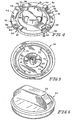
- Filler neck cap 10 includes an axially inner portion (closure) 12 adapted to close a filler neck 14, an axially outer portion 16 rotatable about an axis of rotation 18, and a torque-limit signaler 20 coupled to axially inner and outer portions 12, 16 as suggested in Fig. 1.
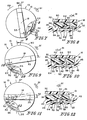
- Torque-limit signaler 20 operates to interrupt temporarily a driving (i.e. torque-transmitting) connection between axially outer portion 16 and closure 12 when closure 12 is seated properly in filler neck 14 during installation of cap 10 in filler neck 14 as shown, for example, in Figs. 11 and 12.
- This temporary interruption functions to "signal" a user rotating axially outer portion 16 in a clockwise, cap-advancing direction during installation of cap 10 in filler neck 14 that sufficient torque has been applied to axially outer portion 16 by the user during installation of closure 12 in filler neck 14 to seat closure 12 in a filler neck-closing position in filler neck 14.
- Closure 12 is a filler neck closure comprising a closure base 22, an O-ring seal 24 carried on an outer surface of closure base 22, and a radially extending annular flange 26 coupled to closure base 22 and arranged to overlie O-ring seal 24 as shown diagrammatically in Fig. 1 and illustratively in Figs. 2 and 3.
- Closure base 22 and radially extending annular flange 26 cooperate to form a monolithic component made of a suitable plastics material.
- a valve assembly 28 including a pressure-relief valve and a vacuum-relief valve is mounted in an axially extending passageway formed in a central portion of closure base 22 as suggested in Fig. 2.
- Closure base 22 and O-ring seal 24 cooperate to close an open-mouth 30 of filler neck 14 upon movement of closure 12 to assume a filler neck-closing position in filler neck 14.
- Axially outer portion 16 comprises a rotatable handle 32, a rotatable torque-transmission member 34 under handle 32, a lost-motion driver 36 coupled to handle 32 and to torque-transmission member 34, and a rotary (e.g. torsion) spring 38 coupled to handle 32 and torque-transmission member 34 as shown diagrammatically in Fig. 1 and illustratively in Figs. 2 and 3.
- a retainer 40 is provided to couple handle 32 to radially extending annular flange 26 as suggested for example, in Figs. 2 and 3 to permit handle 32 (and torque-transmission member 34) to rotate relative to closure 12 about axis of rotation 18 at various stages of cap installation in and removal from filler neck 14.
- Torque-limit signaler 20 is configured to provide a temporary torque-limited driving connection between axially outer and inner portions 16, 12. Torque-limit signaler 20 transmits torque from rotatable torque-transmission member 34 to axially inner portion (closure) 12 to cause closure 12 to turn in filler neck 14 during cap installation (in response to rotation of handle 32 and torque-transmission member 34) until closure 12 is installed in filler neck 14 and the torque applied by torque-transmission member 34 to closure 12 begins to exceed a predetermined or preset torque limit.
- torque-limit signaler 20 produces an audible and/or tactile and/or other receivable signal to a user so that the user will know not to turn the cap 10 further in a clockwise, cap-advancing direction in filler neck 14, which could lead to "over-tightening" the cap 10 in the filler neck 14.
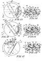
- torque-limit signaler 20 includes a first set of components and notches provided on an axially inwardly facing underside 42 of torque-transmission member 34 and a second set of components and slots provided on a topside 43 of closure 12 as shown diagrammatically in Fig. 1a and illustratively in Figs. 2, 4, 5, and 7-18. As shown and described herein, these two sets of components interact with one another to generate a torque-limit signal during cap installation to alert a user to cease rotating handle 32 in a clockwise, cap-advancing direction. In the embodiment illustrated in Figs. 2-18, there are four torque-limit signaler "units" 20 provided in circumferentially spaced-apart positions at about 90° intervals around the circumference of cap 10.
- each torque-limit signaler 20 comprises a first lug 50, a second lug 52, a flexible spring arm 54, and a spring head 55 on an end of spring arm 54.
- First and second lugs 50, 52 are appended to underside 42 of torque-transmission member 34 and spaced apart to define a drive notch 56 therebetween.
- Torque-transmission member 34 is also formed to include a head retainer notch 58 arranged so that first lug 50 lies between drive notch 56 and head retainer notch 58.
- Drive notch 56 and head retainer notch 58 are sized and located to receive at least a portion of spring head 55 therein at various points during cap installation and removal.
- One end of spring arm 54 is cantilevered to closure 12 and an opposite end of spring arm 54 carries spring head 55 up and down as the spring arm 54 flexes, bends, or deflects during cap installation and removal.
- torque-transmission member 34 includes a central portion formed to include a central rotary spring cup 81 and a flat ring arranged to extend around cup 81 and formed to include arcuate lost-motion drive slots 70. Torque-transmission member 34 also includes a radially extending annular rim surrounding the central portion and formed to include the four sets of first and second lugs 50, 52.
- Spring arm 54 and spring head 55 cooperate to define a first drive receiver coupled to closure 12 as shown, for example, in Fig. 2.
- First drive receiver 54, 55 is arranged to contact first lug 50 as shown, for example, on Figs. 7 and 8 to enable closure 12 to "receive" torque transmitted by axially outer portion 16 to cause closure 12 to rotate about axis 18 in filler neck 14 in response to rotation of axially outer portion 16 in a clockwise, cap-advancing direction during a first stage of cap installation in filler neck 14.
- Radially extending annular flange 26 of closure 12 is formed to include four lost-motion signal slots 60 and each spring arm 54 is arranged to extend into one of the four lost-motion signal slots 60 as shown, for example, in Figs. 2, 7, and 8.
- an interior edge 62 of radially extending annular flange 26 defines lost-motion signal slot 60 and one end of spring arm 54 is cantilevered to one portion of interior edge 62.
- a portion of interior edge 62 opposite to spring head 55 defines a second drive receiver 64 that is to contact second lug 52 when second lug 52 has moved in slot 60 to assume a first extreme position in which closure 12 is seated in the filler neck-closing position as shown, for example, in Figs. 11 and 12.
Landscapes
- Engineering & Computer Science (AREA)
- Life Sciences & Earth Sciences (AREA)
- Sustainable Development (AREA)
- Sustainable Energy (AREA)
- Chemical & Material Sciences (AREA)
- Combustion & Propulsion (AREA)
- Transportation (AREA)
- Mechanical Engineering (AREA)
- Cooling, Air Intake And Gas Exhaust, And Fuel Tank Arrangements In Propulsion Units (AREA)
- Closures For Containers (AREA)
- Sealing Of Jars (AREA)
Description
an axially outer portion (16) rotatable about an axis of rotation,
an axially inner portion (12) adapted to close the filler neck, and
a torque-limit signaler (20) coupled to the axially outer and inner portions and configured to disable temporarily transmission of torque about the axis of rotation in a cap-advancing direction from the axially outer portion to the axially inner portion during rotation of the axially outer portion about the axis of rotation in the cap advancing direction to signal a person rotating the outer portion that the axially inner portion is seated in a filler neck-closing position, the torque-limit signaler comprising
a first drive receiver (54, 55) coupled to the axially inner portion for movement relative to the axially inner portion between an axially raised position and an axially lowered position,
a first lug (50) coupled to the axially outer portion to rotate therewith and contact the first drive receiver in the raised position during rotation of the axially outer portion about the axis of rotation in the cap-advancing direction to cause the axially inner portion to rotate about the axis of rotation, the first lug being formed to include an inclined first drive surface (66) configured to urge the first driver receiver in an axially inner direction from the axially raised position to the axially lowered position to allow limited lost-motion rotation of the axially outer portion relative to the axially inner portion once torque in excess of a predetermined amount is applied to the axially outer portion about the axis of rotation during continued rotation of the axially outer portion about the axis of rotation in the cap-advancing direction,
a second lug (52) coupled to the axially outer portion to rotate therewith and formed to include a second drive surface, and
a second drive receiver.
Claims (19)
- A torque-limit signal cap (10) for a filler neck (14), the cap comprising
an axially outer portion (16) rotatable about an axis of rotation,
an axially inner portion (12) adapted to close the filler neck, and
a torque-limit signaler (20) coupled to the axially outer and inner portions and configured to disable temporarily transmission of torque about the axis of rotation in a cap-advancing direction from the axially outer portion to the axially inner portion during rotation of the axially outer portion about the axis of rotation in the cap advancing direction to signal a person rotating the outer portion that the axially inner portion is seated in a filler neck-closing position, the torque-limit signaler comprising
a first drive receiver (54, 55) coupled to the axially inner portion for movement relative to the axially inner portion between an axially raised position and an axially lowered position,
a first lug (50) coupled to the axially outer portion to rotate therewith and contact the first drive receiver in the raised position during rotation of the axially outer portion about the axis of rotation in the cap-advancing direction to cause the axially inner portion to rotate about the axis of rotation, the first lug being formed to include an inclined first drive surface (66) configured to urge the first driver receiver in an axially inner direction from the axially raised position to the axially lowered position to allow limited lost-motion rotation of the axially outer portion relative to the axially inner portion once torque in excess of a predetermined amount is applied to the axially outer portion about the axis of rotation during continued rotation of the axially outer portion about the axis of rotation in the cap-advancing direction,
a second lug (52) coupled to the axially outer portion to rotate therewith and formed to include a second drive surface, and
a second drive receiver (64) coupled to the axially inner portion and located to contact the second drive surface provided on the second lug after limited lost motion rotation of the axially outer portion relative to the axially inner portion about the axis of rotation in the cap-advancing direction to apply a clockwise torque to the axially inner portion to re-establish torque transmitting connection in the cap advancing direction without further lost motion and to provide a torque-limit signal indicating to a person rotating the axially outer portion about the axis of rotation in the cap-advancing direction that such limited lost-motion rotation of the axially outer portion relative to the axially inner portion has occurred and sufficient torque has been applied to the axially outer portion about the axis of rotation in the cap-advancing direction during installation of the axially inner portion in a filler neck to seat the axially inner portion in a filler neck-closing position in the filler neck. - The cap of claim 1, wherein the second lug (52) includes a third drive surface (53) positioned to lie in spaced-apart relation to the inclined first drive surface provided on the first lug (50) to define a drive notch (56) therebetween and the first drive receiver includes a flexible spring arm (54) coupled at one end to the axially inner portion and provided with a spring head (55) at an opposite end that is arranged to extend into the drive notch (56) when the first drive receiver lies in the axially raised position to maintain contact with the inclined first drive surface on the first lug to provide a torque-limited connection during rotation of the axially outer portion about the axis of rotation in the cap-advancing direction.
- The cap of claim 2, wherein the axially outer portion includes a handle (32) rotatable about the axis of rotation and a torque-transmission member (34) positioned to lie between the handle and the axially inner portion and formed to include an axially inwardly facing surface (42) and the first and second lugs are appended to the axially inwardly facing surface of the torque-transmission member.
- The cap of claim 3, wherein the torque-transmission member is formed to include a head retainer notch (58) having a head-receiving opening in the axially inwardly facing surface and receiving the spring head therein when the second drive surface on the second lug contacts the second drive receiver on the axially inner portion and the first lug is positioned to lie between the drive notch and the head retainer notch formed in the torque-transmission member.
- The cap of claim 2, wherein the axially upper portion is formed to include a head retainer notch (58) arranged to receive the spring head therein when the second drive surface on the second lug contacts the second drive receiver on the axially inner portion.
- The cap of claim 5, wherein the first lug is positioned on the axially upper portion to lie between the drive notch and the head retainer notch and arranged to maintain contact with the spring head during flexure of the spring arm from the axially raised position to the axially lowered position and the spring arm is configured to provide means for yieldably urging the spring head, into the head retainer notch at about the point that the second drive surface on the second lug contacts the second drive receiver on the axially inner portion allowing the spring head to move to assume the axially raised position in the head retainer notch to produce an audible snapping sound associated with the torque-limit signal to provide notice to the person rotating the axially outer portion to cease rotating the axially outer portion in the cap-advancing direction.
- The cap of claim 2, wherein the spring head (55) is formed to include an inclined surface (unnumbered) arranged to mate with the inclined first drive surface on the first lug during rotation of the axially outer portion about the axis of rotation in the cap-advancing direction as long as torque that is not in excess of the predetermined amount is applied to the axially outer portion and the spring head is formed to include a third drive receiver (unnumbered) arranged to mate with the third drive surface on the second lug during rotation of the axially outer portion in a cap-removal direction (89) that is opposite to the cap-advancing direction (91).
- The cap of claim 7, wherein the axially inner portion is formed to include an interior edge (62) defining a lost-motion signal slot (70), the spring arm is cantilevered to the interior edge to extend into the lost-motion signal slot and to position the spring head for movement relative to the axially inner portion as the first drive receiver is moved between the axially raised and lowered positions, and one portion of the interior edge defines the second receiver surface and lies in spaced apart confronting relation to the spring head.
- The cap of claim 1, wherein the axially inner portion includes a closure base (22), an O-ring seal (24) around an exterior surface of the closure base, and a radially extending annular flange (26) positioned to overlie the O-ring seal and formed to include an interior edge defining a lost-motion signal slot (70), the first drive receiver includes a spring arm (54) cantilevered at one end to one portion of the interior edge and provided with a spring head (55) at an opposite end, the spring arm is arranged to extend into the lost-motion signal slot, and another portion of the interior edge defines the second receiver surface and lies in spaced-apart confronting relation to the spring head.
- The cap of claim 9, wherein the second lug is positioned to move back and forth in the lost-motion signal slot from a first extreme position contacting the second drive receiver to an opposite second extreme positioning contacting a third drive receiver provided on the spring head.
- The cap of claim 10, wherein the axially upper portion is formed to include a head retainer notch (58) and a drive notch (56) positioned to lie between the second lug and the head retainer notch and the spring head is positioned to lie in the head retainer notch when the second lug is in the first extreme position and to lie in the drive notch when the second lug is in the opposite second extreme position.
- The cap of claim 9, wherein the second lug is positioned to move back and forth in the lost-motion signal slot from a first extreme position contacting the second drive receiver to an opposite second extreme position contacting a third drive receiver provided on the spring head, the axially upper portion is formed to include a head retainer notch (58) and a drive notch (56) positioned to lie between the second lug and the head retainer notch, the spring head is positioned to lie in the head retainer notch when the second lug is in the first extreme position and to lie in the drive notch when the second lug is in the opposite second extreme position, the first lug is positioned to lie between the drive notch and the head retainer notch, and the spring head is urged by the spring arm to maintain contact with the first lug during movement of the second lug in the lost-motion signal slot between the first and second extreme positions to produce an audible snapping sound associated with the torque-limit signal upon movement of the spring head into the head retainer notch to provide notice to the person rotating the axially outer portion to cease rotating the axially outer portion in the cap-advancing direction.
- The cap of claim 9, wherein the axially outer portion includes a handle (32) located over the radially extending annular flange and a torque-transmission member (34) located between the handle and the radially extending annular flange, and further comprising a lost-motion driver (36) comprising a first arcuate lost-motion drive slot (70) formed in the torque-transmission member and a first drive post (75) mounted on an underside of the handle and arranged to extend into the first arcuate lost-motion drive slot and move therein along an arc length thereof during rotation of the handle about the axis of rotation relative to the torque-transmission member.
- The cap of claim 13, further comprising a rotary spring (38) coupled at one end to the handle and at another end to the torque-transmission member.
- The cap of claim 9, wherein the torque-transmission member includes a central portion and a radially extending annular rim surrounding the central portion, the radially extending annular rim is positioned to overlie the radially extending annular flange of the axially inner portion and formed to include the first and second lugs, and the central portion is formed to include the first arcuate lost motion drive slot.
- The cap of claim 15, wherein the central portion includes a central rotary spring mount cup (81) and a flat ring arranged to extend around the central rotary spring mount cup and formed to include the first arcuate lost-motion drive slot and further comprising a rotary spring (38) coupled at one end to the handle and at another end to the central rotary spring mount cup.
- The cap of claim 1, wherein the axially outer portion includes a handle (32) rotatable about the axis of rotation and a torque-transmission member (34) positioned to lie between the handle and the axially inner portion, the torque transmission member is formed to include an axially inwardly facing surface (42), and the first and second lugs are appended to the axially inwardly facing surface of the torque transmission member.
- The cap of claim 17, wherein the first and second lugs cooperate to define a drive notch (56) therebetween, the torque-transmission member is formed to include a head retainer notch (58), the first lug is positioned to lie between the drive notch and the head retainer notch, the first drive receiver includes a spring arm (54) cantilevered at one end to the axially inner portion and provided with a spring head (56) at an opposite end that is arranged to extend into the drive notch when the second lug is located to contact the spring head and to extend into the head retainer notch when the second drive surface on the second lug is located to contact the second drive receiver.
- The cap of claim 18, wherein the axially inner portion includes a closure base (22), an O-ring seal (24) around an exterior surface of the closure base, and a radially extending annular flange (26) positioned to overlie the O-ring seal, the radially extending annular flange is formed to include an interior edge defining a lost-motion signal slot (70), and the second lug depends from the torque-transmission member and is positioned to move back-and forth in the lost-motion signal slot from a first extreme position contacting the second drive receiver provided on a portion of the interior edge and an opposite second extreme position contacting a third drive receiver provided on the spring head.
Applications Claiming Priority (3)
| Application Number | Priority Date | Filing Date | Title |
|---|---|---|---|
| US23341500P | 2000-09-18 | 2000-09-18 | |
| US233415P | 2000-09-18 | ||
| PCT/US2001/028894 WO2002022454A1 (en) | 2000-09-18 | 2001-09-18 | Torque-limit signal system for filler neck cap |
Publications (3)
| Publication Number | Publication Date |
|---|---|
| EP1401722A1 EP1401722A1 (en) | 2004-03-31 |
| EP1401722A4 EP1401722A4 (en) | 2004-07-28 |
| EP1401722B1 true EP1401722B1 (en) | 2005-12-28 |
Family
ID=22877149
Family Applications (1)
| Application Number | Title | Priority Date | Filing Date |
|---|---|---|---|
| EP01973063A Expired - Lifetime EP1401722B1 (en) | 2000-09-18 | 2001-09-18 | Torque-limit signal system for filler neck cap |
Country Status (5)
| Country | Link |
|---|---|
| US (2) | US6763966B2 (en) |
| EP (1) | EP1401722B1 (en) |
| CA (1) | CA2419980C (en) |
| DE (1) | DE60116391T2 (en) |
| WO (1) | WO2002022454A1 (en) |
Families Citing this family (37)
| Publication number | Priority date | Publication date | Assignee | Title |
|---|---|---|---|---|
| JP3952701B2 (en) * | 2001-03-30 | 2007-08-01 | 豊田合成株式会社 | Tank cap |
| JP2004035016A (en) * | 2002-07-01 | 2004-02-05 | Nifco Inc | Fuel tank capping device |
| DE20211232U1 (en) * | 2002-07-18 | 2003-11-20 | Reutter, Heinrich, 71336 Waiblingen | cap |
| US7048138B2 (en) * | 2002-07-22 | 2006-05-23 | Toyoda Gosei Co., Ltd. | Cap device |
| DE102004038864B4 (en) * | 2003-08-11 | 2010-05-12 | Toyoda Gosei Co., Ltd., Nishikasugai-gun | cap device |
| DE20313900U1 (en) * | 2003-09-04 | 2003-12-18 | Blau Kunststofftechnik Zweigniederlassung Der Tesma Europa Gmbh | Lids, especially fuel caps |
| DE602004021159D1 (en) * | 2003-09-05 | 2009-07-02 | Toyoda Gosei Kk | filler cap |
| US7278547B2 (en) * | 2003-09-05 | 2007-10-09 | Toyoda Gosei Co., Ltd. | Cap device |
| JP4406546B2 (en) * | 2003-09-05 | 2010-01-27 | 豊田合成株式会社 | Cap device |
| JP4327574B2 (en) * | 2003-12-04 | 2009-09-09 | 株式会社アステア | Filler cap |
| JP4596821B2 (en) * | 2004-05-28 | 2010-12-15 | 株式会社アステア | Oil filler cap |
| US7267015B2 (en) * | 2004-09-20 | 2007-09-11 | Quantum Corporation | System and method for testing media device doors |
| US20060124644A1 (en) * | 2004-12-13 | 2006-06-15 | James Dehn | Ratcheted fuel cap |
| US7131469B2 (en) * | 2005-01-10 | 2006-11-07 | Dunkle Gary L | Outdoor tool fuel cap |
| DE602007007901D1 (en) * | 2006-01-20 | 2010-09-02 | Bemis Mfg Co | Method for assembling a modular pawl lock |
| GB2435032A (en) * | 2006-02-09 | 2007-08-15 | Christopher Conan Blythe | Fuel filler cap with warning to prevent incorrect fuelling |
| DE102006031463A1 (en) * | 2006-07-07 | 2008-01-10 | Itw Automotive Products Gmbh & Co. Kg | Filler neck for filling diesel fuel into a vehicle tank |
| US8567628B2 (en) * | 2008-10-14 | 2013-10-29 | Stant Usa Corp. | Fuel cap with fuel-tank pressure/vacuum dissipation control system |
| US8596483B2 (en) * | 2010-01-11 | 2013-12-03 | Novo Motor Acoustic Systems Inc. | Rotatable access closure element |
| US8740002B2 (en) * | 2010-03-04 | 2014-06-03 | Stant Usa Corp. | Cap-installation signal system for filler neck cap |
| US8434634B2 (en) | 2010-05-13 | 2013-05-07 | Bemis Manufacturing Company | Ratcheting gauge cap |
| EP2714537B1 (en) * | 2011-05-25 | 2016-06-08 | Stant USA Corp. | Cap-installation signal system for filler neck cap |
| US9986919B2 (en) | 2011-06-21 | 2018-06-05 | Masimo Corporation | Patient monitoring system |
| US9532722B2 (en) | 2011-06-21 | 2017-01-03 | Masimo Corporation | Patient monitoring system |
| USD692738S1 (en) | 2011-06-30 | 2013-11-05 | Hellermanntyton Corporation | Cable tie tensioning and cut-off tool |
| US8955556B2 (en) | 2011-06-30 | 2015-02-17 | Hellermanntyton Corporation | Cable tie tensioning and cut-off tool |
| US9132568B2 (en) * | 2011-10-11 | 2015-09-15 | Echo, Inc. | Chainsaw with cutting chain tensioner |
| CN103318015A (en) * | 2013-06-08 | 2013-09-25 | 杭叉集团股份有限公司 | Fuel tank for forklift |
| WO2015020911A2 (en) | 2013-08-05 | 2015-02-12 | Cercacor Laboratories, Inc. | Blood pressure monitor with valve-chamber assembly |
| US10182609B2 (en) * | 2014-07-28 | 2019-01-22 | Speedplay, Inc. | Aperture cover for bicycle cleat assembly |
| US10259604B2 (en) | 2014-12-12 | 2019-04-16 | Hellermanntyton Corporation | Compound tension and calibration mechanism for cable tie tensioning and cut-off tool |
| JP6960316B2 (en) * | 2017-11-30 | 2021-11-05 | 株式会社マーレ フィルターシステムズ | Oil pan drain plug structure |
| CN112026509B (en) * | 2020-09-02 | 2024-10-18 | 宁波舜江汽车部件制造有限公司 | High-pressure fuel tank cap assembly of automobile |
| USD1071995S1 (en) * | 2020-09-21 | 2025-04-22 | Fna Group, Inc. | Filler assembly |
| US12017525B2 (en) | 2021-10-27 | 2024-06-25 | Stant Usa Corp. | Fuel cap |
| US12085216B2 (en) * | 2022-02-17 | 2024-09-10 | Arctic Cat Inc. | Multi-use fuel filler tube |
| US12498066B1 (en) * | 2024-06-12 | 2025-12-16 | Ho Sing Enterprises Co., Ltd. | Quick connector structure of fluid shock absorber |
Family Cites Families (22)
| Publication number | Priority date | Publication date | Assignee | Title |
|---|---|---|---|---|
| US4083209A (en) | 1977-06-29 | 1978-04-11 | Stant Manufacturing Company, Inc. | Low profile threaded lock cap |
| US4280347A (en) | 1979-05-21 | 1981-07-28 | Stant Inc. | Torque override threaded locking cap |
| US4280346A (en) | 1979-05-21 | 1981-07-28 | Stant Inc. | Torque override threaded locking cap |
| DE8512655U1 (en) | 1985-04-29 | 1985-06-13 | Sid-Werk GmbH, 4048 Grevenbroich | Lid for the filler neck of a container |
| US4765505A (en) | 1986-07-22 | 1988-08-23 | Stant Inc. | Delayed actuation fuel cap |
| US4913303A (en) | 1987-06-16 | 1990-04-03 | Stant Inc. | Liquid splash control fuel cap |
| US5110003A (en) | 1990-06-28 | 1992-05-05 | Stant Inc. | Torque-override cap |
| US5108001A (en) * | 1990-07-03 | 1992-04-28 | Stant Inc. | Pressure release vent cap |
| US5449086A (en) | 1993-10-18 | 1995-09-12 | Stant Manufacturing Inc. | Delayed actuation fuel cap |
| US5638975A (en) | 1994-05-06 | 1997-06-17 | Stant Manufacturing Inc. | Lost motion fuel cap with cap closure indicator |
| US5480055A (en) * | 1994-05-06 | 1996-01-02 | Stant Manufacturing Inc. | Quick-on cap with removal delay mechanism |
| US5794806A (en) | 1994-05-06 | 1998-08-18 | Stant Manufacturing Inc. | Quick-on fuel cap |
| US5732841A (en) * | 1996-03-19 | 1998-03-31 | Tesma International Inc. | Fuel cap |
| EP1070009B1 (en) | 1997-01-16 | 2007-08-29 | Stant Manufacturing Inc. | Quick-on filler neck cap |
| WO1998047787A1 (en) * | 1997-04-21 | 1998-10-29 | Stant Manufacturing Inc. | Lockable fuel cap |
| WO1999005026A2 (en) * | 1997-07-23 | 1999-02-04 | Stant Manufacturing Inc. | Fuel cap |
| WO1999010636A1 (en) * | 1997-08-21 | 1999-03-04 | Tesma International Inc. | Coolant container cap assembly |
| AT408869B (en) * | 1998-01-30 | 2002-03-25 | Tesma Motoren Getriebetechnik | CLOSURE LID |
| DE29811706U1 (en) * | 1998-07-01 | 1998-09-10 | H. Köhler GmbH, 59558 Lippstadt | Device for monitoring the closed position of a tank cap |
| CA2339980A1 (en) | 1998-10-06 | 2000-04-13 | Robert S. Harris | Quick-on torque-override filler neck cap |
| DE19910684C2 (en) * | 1999-03-10 | 2001-02-01 | Gerdes Gmbh | Fuel cap with free passage |
| DE60013941T2 (en) | 1999-03-31 | 2005-10-20 | Toyoda Gosei Co., Ltd., Nishikasugai | Fuel cap and fuel tank provided therewith |
-
2001
- 2001-09-18 US US09/955,350 patent/US6763966B2/en not_active Expired - Lifetime
- 2001-09-18 US US10/343,876 patent/US6739472B2/en not_active Expired - Fee Related
- 2001-09-18 EP EP01973063A patent/EP1401722B1/en not_active Expired - Lifetime
- 2001-09-18 WO PCT/US2001/028894 patent/WO2002022454A1/en not_active Ceased
- 2001-09-18 CA CA002419980A patent/CA2419980C/en not_active Expired - Fee Related
- 2001-09-18 DE DE60116391T patent/DE60116391T2/en not_active Expired - Fee Related
Also Published As
| Publication number | Publication date |
|---|---|
| US20030205578A1 (en) | 2003-11-06 |
| US20020066734A1 (en) | 2002-06-06 |
| CA2419980A1 (en) | 2002-03-21 |
| EP1401722A1 (en) | 2004-03-31 |
| CA2419980C (en) | 2005-01-11 |
| WO2002022454A1 (en) | 2002-03-21 |
| US6763966B2 (en) | 2004-07-20 |
| US6739472B2 (en) | 2004-05-25 |
| DE60116391T2 (en) | 2006-07-27 |
| EP1401722A4 (en) | 2004-07-28 |
| DE60116391D1 (en) | 2006-02-02 |
Similar Documents
| Publication | Publication Date | Title |
|---|---|---|
| US6739472B2 (en) | Torque-limit signal system for filler neck cap | |
| EP0252577B1 (en) | Breakaway gas cap | |
| US5638975A (en) | Lost motion fuel cap with cap closure indicator | |
| KR100441930B1 (en) | Fuel cap and filler neck fitment | |
| US8567628B2 (en) | Fuel cap with fuel-tank pressure/vacuum dissipation control system | |
| US4765505A (en) | Delayed actuation fuel cap | |
| US5524870A (en) | Torque-override winch | |
| US20110240643A1 (en) | Cap-installation signal system for filler neck cap | |
| CA2314273C (en) | Tamper-indicating closure | |
| US6745914B2 (en) | Cap device | |
| US6554150B2 (en) | Contaminant cover for tank filler neck closure assembly | |
| US5110003A (en) | Torque-override cap | |
| EP1332979A1 (en) | Cap device | |
| EP0723516A1 (en) | Delayed actuation fuel cap | |
| WO1995030592A1 (en) | Quick-on cap with removal delay mechanism | |
| JPH11501889A (en) | Containers with lids that cannot be easily removed | |
| US20170015194A1 (en) | Cap-installation signal system for filler neck cap | |
| US20080110890A1 (en) | Resin member and method of manufacturing the same | |
| US7131469B2 (en) | Outdoor tool fuel cap | |
| WO1996029276A1 (en) | Can opener | |
| WO2007032539A1 (en) | Screw cap and safety cap | |
| EP0947367B1 (en) | Filler cap | |
| JP3745806B2 (en) | Pilfer proof cap | |
| JP2523969Y2 (en) | Fuel cap with lock | |
| HK1192527B (en) | Cap-installation signal system for filler neck cap |
Legal Events
| Date | Code | Title | Description |
|---|---|---|---|
| PUAI | Public reference made under article 153(3) epc to a published international application that has entered the european phase |
Free format text: ORIGINAL CODE: 0009012 |
|
| 17P | Request for examination filed |
Effective date: 20030307 |
|
| AK | Designated contracting states |
Kind code of ref document: A1 Designated state(s): DE FR GB |
|
| A4 | Supplementary search report drawn up and despatched |
Effective date: 20040616 |
|
| RIC1 | Information provided on ipc code assigned before grant |
Ipc: 7B 60K 15/04 B Ipc: 7B 65D 41/06 A |
|
| 17Q | First examination report despatched |
Effective date: 20040923 |
|
| GRAP | Despatch of communication of intention to grant a patent |
Free format text: ORIGINAL CODE: EPIDOSNIGR1 |
|
| GRAS | Grant fee paid |
Free format text: ORIGINAL CODE: EPIDOSNIGR3 |
|
| GRAA | (expected) grant |
Free format text: ORIGINAL CODE: 0009210 |
|
| AK | Designated contracting states |
Kind code of ref document: B1 Designated state(s): DE FR GB |
|
| REG | Reference to a national code |
Ref country code: GB Ref legal event code: FG4D |
|
| REF | Corresponds to: |
Ref document number: 60116391 Country of ref document: DE Date of ref document: 20060202 Kind code of ref document: P |
|
| PGFP | Annual fee paid to national office [announced via postgrant information from national office to epo] |
Ref country code: FR Payment date: 20060918 Year of fee payment: 6 |
|
| PGFP | Annual fee paid to national office [announced via postgrant information from national office to epo] |
Ref country code: GB Payment date: 20060925 Year of fee payment: 6 |
|
| ET | Fr: translation filed | ||
| PGFP | Annual fee paid to national office [announced via postgrant information from national office to epo] |
Ref country code: DE Payment date: 20061031 Year of fee payment: 6 |
|
| PLBE | No opposition filed within time limit |
Free format text: ORIGINAL CODE: 0009261 |
|
| STAA | Information on the status of an ep patent application or granted ep patent |
Free format text: STATUS: NO OPPOSITION FILED WITHIN TIME LIMIT |
|
| 26N | No opposition filed |
Effective date: 20060929 |
|
| GBPC | Gb: european patent ceased through non-payment of renewal fee |
Effective date: 20070918 |
|
| PG25 | Lapsed in a contracting state [announced via postgrant information from national office to epo] |
Ref country code: DE Free format text: LAPSE BECAUSE OF NON-PAYMENT OF DUE FEES Effective date: 20080401 |
|
| REG | Reference to a national code |
Ref country code: FR Ref legal event code: ST Effective date: 20080531 |
|
| PG25 | Lapsed in a contracting state [announced via postgrant information from national office to epo] |
Ref country code: FR Free format text: LAPSE BECAUSE OF NON-PAYMENT OF DUE FEES Effective date: 20071001 |
|
| PG25 | Lapsed in a contracting state [announced via postgrant information from national office to epo] |
Ref country code: GB Free format text: LAPSE BECAUSE OF NON-PAYMENT OF DUE FEES Effective date: 20070918 |