EP1401239A2 - Wärmeübertragung in einem Audio-Gerät - Google Patents
Wärmeübertragung in einem Audio-Gerät Download PDFInfo
- Publication number
- EP1401239A2 EP1401239A2 EP03102626A EP03102626A EP1401239A2 EP 1401239 A2 EP1401239 A2 EP 1401239A2 EP 03102626 A EP03102626 A EP 03102626A EP 03102626 A EP03102626 A EP 03102626A EP 1401239 A2 EP1401239 A2 EP 1401239A2
- Authority
- EP
- European Patent Office
- Prior art keywords
- volume
- acoustic
- frustal
- shaped
- accordance
- Prior art date
- Legal status (The legal status is an assumption and is not a legal conclusion. Google has not performed a legal analysis and makes no representation as to the accuracy of the status listed.)
- Granted
Links
Images




Classifications
-
- H—ELECTRICITY
- H04—ELECTRIC COMMUNICATION TECHNIQUE
- H04R—LOUDSPEAKERS, MICROPHONES, GRAMOPHONE PICK-UPS OR LIKE ACOUSTIC ELECTROMECHANICAL TRANSDUCERS; ELECTRIC HEARING AIDS; PUBLIC ADDRESS SYSTEMS
- H04R9/00—Transducers of moving-coil, moving-strip, or moving-wire type
- H04R9/02—Details
- H04R9/022—Cooling arrangements
Definitions
- the invention relates to heat removal from audio devices, and more particularly to a device using air motion generated by an acoustic driver to transfer heat generated by audio amplifiers.
- an acoustic device comprises an acoustic driver, including a frustal shaped vibratile surface defining a frustal shaped volume.
- the vibratile surface has an inner side and an outer side.
- the frustal shaped volume is characterized by an axis.
- a support structure is mechanically coupled to the vibratile surface, extending axially from the inner side.
- the support structure defines a second volume.
- the second volume is contiguous to the frustal shaped volume.
- the frustal shaped volume and the second volume form an inner volume.
- An oscillatory motor device coupled to the vibratile surface, causes the vibratile surface to vibrate in an axial direction, causing air movement in the inner volume.
- the acoustic device further includes a heat producing device, distinct from the oscillatory motor device, mounted so that a substantial portion of the heat producing device is in the inner volume.
- a loudspeaker device is for mounting in a door of a vehicle.
- the door has a passenger compartment facing side and an exterior facing side.
- the loudspeaker device includes an acoustic driver.
- the acoustic driver includes a vibratile pressure wave radiating surface and an amplifier, for amplifying an audio signal for transducing by the acoustic driver.
- the radiating surface is positioned so that the radiating surface is between the amplifier assembly and the exterior facing side.
- an acoustic device comprises an acoustic driver.
- the acoustic driver comprises a frustal shaped vibratile surface defining a frustal shaped volume.
- the vibratile surface has an inner side and an outer side.
- the frustal shaped volume is characterized by an axis.
- a support structure is mechanically coupled to the vibratile surface, and extends axially from the inner side, defining a second volume.
- the second volume is contiguous to the frustal shaped volume.
- the frustal shaped volume and the second volume form an inner volume.
- the acoustic device further includes an oscillatory motor device, coupled to the vibratile surface, for causing the vibratile surface to vibrate in an axial direction.
- the vibration causes air movement in the inner volume.
- the acoustic device also includes a heat producing device, distinct from the oscillatory motor device and a heat sink, thermally coupled to the heat producing device, for transferring heat from the heat producing device.
- the acoustic driver, the heat producing device and the heat sink are constructed and arranged so that a substantial portion of the heat sink is in the inner volume.
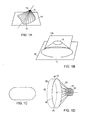
- a cone 8, (or cone surface), as used herein, shown in FIG. 1a is a surface generated by a line, typically straight, which moves so that it always intersects a closed plane curve, called the directrix 12, and passes through a point 14, called the vertex , not in the plane 10 of the directrix 12.
- the generating line in each of its position is referred to as an element.
- a frustum, shown in FIG. 1b is a solid figure bounded by a portion of plane 10 bounded by the directrix 12, the cone, and a portion of a second plane 10b parallel to plane 10.
- the portion of plane 10b that bounds the frustum is the closed curve formed by the intersection 13 of cone 8 with the plane 10b.
- a frustal shaped surface refers to the surface of a frustum defined by the cone.
- a frustal shaped volume refers to the volume bounded by the frustal shaped surface and the two planes 10 and 10b, or in other words the volume occupied by the frustum corresponding to the frustal shaped surface.
- the directrix and the intersection 13 of the cone and second plane 10b may be a circle, and may also be some shape other than a circle, such as oval or a figure defined by two semicircles joined by straight lines as shown in FIG.
- the frustum bounded by the frustal shaped surface is a right frustum, that is, a frustum in which the axis (a line passing through the vertex and the centers of the areas bounded by the closed curves in planes 10 and 10b) is perpendicular to planes 10 and 10b.
- FIG. 1d shows the radiating surface 15 of an acoustic driver in the form of a right frustal shaped surface, with an axis 20.
- the radiating surface has two sides 80 and 82.
- One side 80 hereinafter the inner side, is the side that faces the frustal shaped volume 25.
- the second side 82 hereinafter the outer side, is the side that faces away from the frustal shaped volume.
- a portion of an oscillatory motor such as a coil former 16 wrapped with a coil 18, is mechanically coupled to the radiating surface.
- a portion 85 of a support structure may extend in an axial direction from the inner side of the radiating surface in such a manner as to enclose a volume 25a contiguous to the frustal shaped volume.
- the volume consisting of the frustal shaped volume 25 and the contiguous volume 25a will hereinafter be referred to as the inner volume.
- the frame member may not extend axially from the inner side of the radiating surface, so that the contiguous volume is essentially zero and the inner volume is substantially coincident with the frustal shaped volume 25.
- the support structure 88 will be described in more detail in subsequent views.
- the motor structure may be positioned on the inner side of the radiating surface, as indicated by the dashed lined.
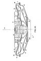
- An acoustic driver 22 includes a driver cone 24 that is in the form of a frustal shaped surface.
- Driver cone 24 encloses a frustal shaped volume 25.
- oscillatory motor structure 26 is in the frustal shaped volume.
- the inner side 80' of the driver cone 24 faces frustal shaped volume 25.
- the outer side 82' of the driver cone 24 faces away from the frustal shaped volume.
- a support structure 88 includes a basket portion 84 and a frame portion 86.
- a portion of the support structure 88, such as frame portion 86 may extend axially away from the inner side of the driver cone 24 so as to enclose a volume 25a contiguous to frustal shaped volume 25.
- the combined volumes 25 and 25a comprise the inner volume.
- the frame portion 86 may not extend axially, so that the inner volume is substantially coincident with the frustal shaped volume.
- Coupling the driver cone 24 to the support structure 88 may be a spider 90 and a surround 92.
- the scrim layer On the inner side of the driver cone 24, in the inner volume (combined volumes 25 and 25a) may be scrim layer 96.
- the scrim layer which has been removed in FIG. 3c, is a layer of a low acoustic resistance (ideally acoustically transparent) material, which protects the driver cone 24.
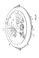
- the amplifier assembly 28 includes an amplifier cover 30, which holds an amplifier (not shown) in thermal contact with a heat sink 32, which will be described in more detail below.
- Amplifier assembly 28 is secured to the supporting structure of the acoustic driver 22 by an attachment assembly having fastener receptacles 34 which protrude through openings 36 in the scrim layer 96.
- Fastener receptacles 34 accommodate fasteners, not shown, to hold the amplifier assembly in place.
- Connector receptacle 37 accommodates a connector, not shown, which transmits audio signals and electrical power to the amplifier assembly.
- Amplifier assembly 28 is positioned so that a substantial portion, preferably all, of the amplifier assembly is in the inner volume.
- the motion of the oscillatory motor causes the cone portion of the acoustic driver to vibrate in an axial direction and to radiate pressure waves, which, at audible frequencies, are sound waves.
- the vibration of the vibratile surface causes air motion in the inner volume, in which the amplifier assembly is positioned. The air motion facilitates heat transfer from the amplifier assembly.
- the acoustic driver is an ND® Woofer manufactured by Bose Corporation of Framingham, Massachusetts, USA.
- the amplifier may be a conventional linear or switching amplifier.
- Cone surface 24' may be made of treated paper.
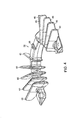
- an audio device for an audio device according to the invention is mounting the assembly in a car door so that it protrudes through the trim 43 so that the amplifier assembly 28 is between the driver cone surface 24 and the passenger compartment (that is, the listening area) facing side 39 of the door, or, stated differently, the audio device is positioned so that the amplifier assembly is between the driver cone surface and the listening area.
- the portion of the audio device protruding through the trim 43 is covered by a protective grille, not shown in this view.
- a loudspeaker device has many advantages over conventional loudspeaker devices, particularly for mounting in vehicle doors, which are relatively narrow in the direction of cone motion.
- the inner volume which is unused in conventional loudspeaker devices, is used for components that may otherwise cause the loudspeaker device to be larger in the direction of cone motion.
- the heat transfer elements are in a location in which there is significant air motion caused by the cone motion. The air motion facilitates heat transfer. Additionally, transmitting more power to the amplifier causes more cone motion, resulting in more air motion and greater heat transfer capacity to accommodate the greater heat transfer requirement for higher power levels.
- the cone surface provides protection for the amplifier assembly from water and other environmental elements
- Heat sink 32 includes a spine member 38 and fins 40. In operation heat is conducted through spine member 38 to fins 40, which have large surfaces to facilitate the transfer of heat to the external environment.
- FIG. 5 shows spine member 38.
- Spine member 38 is a metal (or other highly thermally conductive material) piece.
- the spine member may be in the form of an arc of a circle, and may be positioned such that the center C of the circle is coaxial with axis 20 of FIGS. 1d and 2a - 2c.
- FIG. 6 shows one of the fins 40 in greater detail.
- the fins are characterized by a height h, a length l , and a thickness t .
- the fins are oriented such the two opposing planar faces are substantially parallel to the spine member, and so that one of the larger dimensions h or I extends in a radial direction relative to the arc of the spine member.
- the fins may be shaped and positioned so that one edge 47 of the fin is substantially parallel to the cone surface or scrim surface 49. The substantially parallel edge enables more of the fin area to be placed closer to the cone surface, which results in more effective heat transfer.
- the configuration and the dimensions of the heat sink may vary depending on the heat transfer requirements.
- the central angle ⁇ of the arc may be a full 360 degrees so that the arc is a complete circle.
- the central angle may be smaller, for example approximately 180 degrees so that the arc is substantially a semicircle.
- the heat sink may be dimensioned and configured so that the thermal contact is concentrated near a point 98 on the spine member 38 that is approximately equidistant between the two extremities, and so that the spine member is tapered so that it is thickest at near the point of thermal contact and thinner at the extremities than at other points of the spine member. If the motor structure 26 requires heat sinking, the heat sink may be configured so that the heat sink is in thermal contact with the motor structure.
- the heat sink may be configured so that no part of it is close enough to the motor structure to heat the motor structure appreciably.
- the spine may be at any radial location, such as near the center of the arc, at an intermediate radial distance as in this example, or at a point near the frame portion 86.
- the spine member is arcuate about a center that is coaxial with axis 20.
- the central angle of the arc is approximately 180 degrees, and the radius of the arc is about 55 mm.
- the spine member is tapered so that it has a cross section of about 183 mm 2 at the thickest point 100 near the middle of the spine member in the middle and has a cross section of about 48.4 mm 2 at the extremities.
- the heat sink assembly includes eight or ten fins having a surface area of up to about 900 mm 2 .
- the arc of the spine member 38 is a full circle and the fins 40 extend radially from the spine member. If the motor structure requires heat sinking, the radius of the spine member inner edge 52 may be made small enough so that the heat sink contacts the motor structure. If the motor structure does not require heat sinking, the radius of the spine member inner edge 52 may be made large enough so that it does not contact the motor structure and so that it does not heat the motor structure or interfere with heat transfer from the motor structure.
- a heat sink according to the invention is advantageous because it can be easily reconfigured for a wide range and variety of heat transfer requirements, while fitting into a small space that would otherwise be unused.
Landscapes
- Physics & Mathematics (AREA)
- Engineering & Computer Science (AREA)
- Acoustics & Sound (AREA)
- Signal Processing (AREA)
- Cooling Or The Like Of Electrical Apparatus (AREA)
- Fittings On The Vehicle Exterior For Carrying Loads, And Devices For Holding Or Mounting Articles (AREA)
- Audible-Bandwidth Dynamoelectric Transducers Other Than Pickups (AREA)
- Amplifiers (AREA)
Applications Claiming Priority (2)
| Application Number | Priority Date | Filing Date | Title |
|---|---|---|---|
| US10/246,331 US7120270B2 (en) | 2002-09-18 | 2002-09-18 | Audio device heat transferring |
| US246331 | 2002-09-18 |
Publications (3)
| Publication Number | Publication Date |
|---|---|
| EP1401239A2 true EP1401239A2 (de) | 2004-03-24 |
| EP1401239A3 EP1401239A3 (de) | 2005-08-24 |
| EP1401239B1 EP1401239B1 (de) | 2009-07-29 |
Family
ID=31946421
Family Applications (1)
| Application Number | Title | Priority Date | Filing Date |
|---|---|---|---|
| EP03102626A Expired - Lifetime EP1401239B1 (de) | 2002-09-18 | 2003-08-21 | Wärmeübertragung in einem Audio-Gerät |
Country Status (5)
| Country | Link |
|---|---|
| US (2) | US7120270B2 (de) |
| EP (1) | EP1401239B1 (de) |
| JP (1) | JP2004120747A (de) |
| CN (1) | CN1491066B (de) |
| DE (1) | DE60328570D1 (de) |
Cited By (1)
| Publication number | Priority date | Publication date | Assignee | Title |
|---|---|---|---|---|
| WO2008018099A1 (en) * | 2006-08-10 | 2008-02-14 | Claudio Lastrucci | Improvements to systems for acoustic diffusion |
Families Citing this family (11)
| Publication number | Priority date | Publication date | Assignee | Title |
|---|---|---|---|---|
| US7177439B2 (en) * | 2003-03-06 | 2007-02-13 | Peavey Electronics Corporation | Methods and apparatus for dissipating heat in a voice coil |
| JP2006060443A (ja) * | 2004-08-19 | 2006-03-02 | Pioneer Electronic Corp | スピーカ装置及びスピーカ装置の放熱部材 |
| EP2713271B1 (de) * | 2005-06-24 | 2015-08-12 | Catalogic Software, Inc. | System und Verfahren zum Hochleistungsschutz von Unternehmensdaten |
| US9378099B2 (en) | 2005-06-24 | 2016-06-28 | Catalogic Software, Inc. | Instant data center recovery |
| US7894623B2 (en) * | 2006-03-22 | 2011-02-22 | Harman International Industries, Incorporated | Loudspeaker having an interlocking magnet structure |
| US8135162B2 (en) * | 2007-11-14 | 2012-03-13 | Harman International Industries, Incorporated | Multiple magnet loudspeaker |
| US9445201B2 (en) * | 2013-11-21 | 2016-09-13 | Harman International Industries, Inc. | Inverted dual coil transducer |
| FR3015166B1 (fr) * | 2013-12-18 | 2017-07-14 | Devialet | Enceinte acoustique comprenant une paroi externe non conductrice de la chaleur, un haut-parleur electrodynamique et un circuit electronique de commande |
| USD769327S1 (en) * | 2014-10-14 | 2016-10-18 | Alvaro MORILLO GARCIA | Audio device |
| US10812910B2 (en) * | 2018-09-14 | 2020-10-20 | Harman International Industries, Incorporated | Inverted motor transducer with front spider |
| JP7666973B2 (ja) * | 2021-04-13 | 2025-04-22 | アルプスアルパイン株式会社 | スピーカ |
Citations (1)
| Publication number | Priority date | Publication date | Assignee | Title |
|---|---|---|---|---|
| US6243472B1 (en) | 1997-09-17 | 2001-06-05 | Frank Albert Bilan | Fully integrated amplified loudspeaker |
Family Cites Families (10)
| Publication number | Priority date | Publication date | Assignee | Title |
|---|---|---|---|---|
| US2030648A (en) | 1931-06-25 | 1936-02-11 | Gen Electric | Magnet system |
| NL7308103A (de) * | 1973-06-12 | 1974-12-16 | ||
| JPS57192200A (en) | 1981-05-20 | 1982-11-26 | Matsushita Electric Ind Co Ltd | Speaker |
| US4625328A (en) | 1983-06-13 | 1986-11-25 | Konutra Industries, Ltd. | Integrated amplifier and speaker system with improved cooling efficiency |
| GB8923681D0 (en) * | 1989-10-20 | 1989-12-06 | Lyth Charles D | Improvements in or relating to loudspeakers |
| FR2762263B1 (fr) * | 1997-04-18 | 1999-07-16 | Rockwell Lvs | Porte de vehicule automobile equipee d'un module multicomposants dont une partie forme une cavite acoustique |
| JP2001136032A (ja) | 1999-11-04 | 2001-05-18 | Mechanical Research:Kk | 音響用増幅器 |
| GB2360899B (en) | 1999-12-17 | 2002-03-27 | Goodmans Loudspeakers Ltd | Coaxial speaker |
| FR2803132B1 (fr) | 1999-12-23 | 2002-05-31 | Valeo Equip Electr Moteur | Systeme de redressement perfectionne pour diodes pastilles |
| GB0102780D0 (en) * | 2001-02-03 | 2001-03-21 | K H Technology Corp | Loudspeaker assemblies |
-
2002
- 2002-09-18 US US10/246,331 patent/US7120270B2/en not_active Expired - Lifetime
-
2003
- 2003-08-21 EP EP03102626A patent/EP1401239B1/de not_active Expired - Lifetime
- 2003-08-21 DE DE60328570T patent/DE60328570D1/de not_active Expired - Lifetime
- 2003-09-16 CN CN03158184.6A patent/CN1491066B/zh not_active Expired - Fee Related
- 2003-09-18 JP JP2003325520A patent/JP2004120747A/ja active Pending
-
2006
- 2006-08-28 US US11/467,845 patent/US7340066B2/en not_active Expired - Fee Related
Patent Citations (1)
| Publication number | Priority date | Publication date | Assignee | Title |
|---|---|---|---|---|
| US6243472B1 (en) | 1997-09-17 | 2001-06-05 | Frank Albert Bilan | Fully integrated amplified loudspeaker |
Cited By (2)
| Publication number | Priority date | Publication date | Assignee | Title |
|---|---|---|---|---|
| WO2008018099A1 (en) * | 2006-08-10 | 2008-02-14 | Claudio Lastrucci | Improvements to systems for acoustic diffusion |
| US8428278B2 (en) | 2006-08-10 | 2013-04-23 | Claudio Lastrucci | Improvements to systems for acoustic diffusion |
Also Published As
| Publication number | Publication date |
|---|---|
| JP2004120747A (ja) | 2004-04-15 |
| EP1401239B1 (de) | 2009-07-29 |
| CN1491066A (zh) | 2004-04-21 |
| US7120270B2 (en) | 2006-10-10 |
| US20060285717A1 (en) | 2006-12-21 |
| US7340066B2 (en) | 2008-03-04 |
| DE60328570D1 (de) | 2009-09-10 |
| US20040052397A1 (en) | 2004-03-18 |
| EP1401239A3 (de) | 2005-08-24 |
| CN1491066B (zh) | 2012-11-14 |
Similar Documents
| Publication | Publication Date | Title |
|---|---|---|
| EP3163908B1 (de) | Lautsprechermodul | |
| US6333575B1 (en) | Vibration exciter | |
| US9807512B2 (en) | Speaker | |
| US7120270B2 (en) | Audio device heat transferring | |
| US6278787B1 (en) | Loudspeakers | |
| US7136501B2 (en) | Acoustically enhanced electro-dynamic loudspeakers | |
| US7316290B2 (en) | Acoustic lens system | |
| US6606390B2 (en) | Loudspeakers | |
| JP2004536541A (ja) | 直接放射と最適放射の音響性能を持つスピーカ | |
| US7158648B2 (en) | Loudspeaker system with extended bass response | |
| US4144416A (en) | Unitary tuned port and loudspeaker frame | |
| US20200196064A1 (en) | Speaker | |
| JP2002528019A (ja) | ラウドスピーカ | |
| US6754362B2 (en) | Speaker and speaker system | |
| EP4586643A1 (de) | Lautsprecher und tonsystem für ein kraftfahrzeug | |
| US8077899B2 (en) | Electronic device and process for mounting microphone therein | |
| CN103618979B (zh) | 平板喇叭 | |
| US20040008863A1 (en) | Frequency response enhancements for electro-dynamic loudspeakers | |
| KR101975973B1 (ko) | 측부 장착형 패시브 라디에이터를 포함하는 무지향성 스피커 | |
| JPS636956Y2 (de) | ||
| KR101975978B1 (ko) | 풀커버형 패시브 라디에이터를 포함하는 무지향성 스피커 | |
| JPH11220783A (ja) | 放熱孔付スピーカ及びそれを用いた電気機器 | |
| JP3010216U (ja) | 平面アンテナ | |
| US20060198548A1 (en) | Frame for speaker device and speaker device | |
| JPS6336798Y2 (de) |
Legal Events
| Date | Code | Title | Description |
|---|---|---|---|
| PUAI | Public reference made under article 153(3) epc to a published international application that has entered the european phase |
Free format text: ORIGINAL CODE: 0009012 |
|
| AK | Designated contracting states |
Kind code of ref document: A2 Designated state(s): AT BE BG CH CY CZ DE DK EE ES FI FR GB GR HU IE IT LI LU MC NL PT RO SE SI SK TR |
|
| AX | Request for extension of the european patent |
Extension state: AL LT LV MK |
|
| RIN1 | Information on inventor provided before grant (corrected) |
Inventor name: SHUMOSIC, LEE J. Inventor name: SUBAT, BRADFORD KYLE Inventor name: SCHUSSLER, JOHN Inventor name: LITTLE, RICHARD WARREN Inventor name: HOWARD, DAMIAN Inventor name: LIEBEL, CRAIG A. Inventor name: ARONSON, SCOTT H. |
|
| PUAL | Search report despatched |
Free format text: ORIGINAL CODE: 0009013 |
|
| AK | Designated contracting states |
Kind code of ref document: A3 Designated state(s): AT BE BG CH CY CZ DE DK EE ES FI FR GB GR HU IE IT LI LU MC NL PT RO SE SI SK TR |
|
| AX | Request for extension of the european patent |
Extension state: AL LT LV MK |
|
| 17P | Request for examination filed |
Effective date: 20060126 |
|
| AKX | Designation fees paid |
Designated state(s): DE GB |
|
| GRAP | Despatch of communication of intention to grant a patent |
Free format text: ORIGINAL CODE: EPIDOSNIGR1 |
|
| RBV | Designated contracting states (corrected) |
Designated state(s): DE FR |
|
| RBV | Designated contracting states (corrected) |
Designated state(s): DE GB |
|
| GRAS | Grant fee paid |
Free format text: ORIGINAL CODE: EPIDOSNIGR3 |
|
| GRAA | (expected) grant |
Free format text: ORIGINAL CODE: 0009210 |
|
| AK | Designated contracting states |
Kind code of ref document: B1 Designated state(s): DE GB |
|
| REG | Reference to a national code |
Ref country code: GB Ref legal event code: FG4D |
|
| REF | Corresponds to: |
Ref document number: 60328570 Country of ref document: DE Date of ref document: 20090910 Kind code of ref document: P |
|
| PLBE | No opposition filed within time limit |
Free format text: ORIGINAL CODE: 0009261 |
|
| STAA | Information on the status of an ep patent application or granted ep patent |
Free format text: STATUS: NO OPPOSITION FILED WITHIN TIME LIMIT |
|
| 26N | No opposition filed |
Effective date: 20100503 |
|
| PGFP | Annual fee paid to national office [announced via postgrant information from national office to epo] |
Ref country code: GB Payment date: 20170829 Year of fee payment: 15 |
|
| PGFP | Annual fee paid to national office [announced via postgrant information from national office to epo] |
Ref country code: DE Payment date: 20180829 Year of fee payment: 16 |
|
| GBPC | Gb: european patent ceased through non-payment of renewal fee |
Effective date: 20180821 |
|
| PG25 | Lapsed in a contracting state [announced via postgrant information from national office to epo] |
Ref country code: GB Free format text: LAPSE BECAUSE OF NON-PAYMENT OF DUE FEES Effective date: 20180821 |
|
| REG | Reference to a national code |
Ref country code: DE Ref legal event code: R119 Ref document number: 60328570 Country of ref document: DE |
|
| PG25 | Lapsed in a contracting state [announced via postgrant information from national office to epo] |
Ref country code: DE Free format text: LAPSE BECAUSE OF NON-PAYMENT OF DUE FEES Effective date: 20200303 |