EP1401192A2 - Creating and updating a printer profile - Google Patents
Creating and updating a printer profile Download PDFInfo
- Publication number
- EP1401192A2 EP1401192A2 EP03255893A EP03255893A EP1401192A2 EP 1401192 A2 EP1401192 A2 EP 1401192A2 EP 03255893 A EP03255893 A EP 03255893A EP 03255893 A EP03255893 A EP 03255893A EP 1401192 A2 EP1401192 A2 EP 1401192A2
- Authority
- EP
- European Patent Office
- Prior art keywords
- color
- difference
- distance
- value
- patch
- Prior art date
- Legal status (The legal status is an assumption and is not a legal conclusion. Google has not performed a legal analysis and makes no representation as to the accuracy of the status listed.)
- Withdrawn
Links
Images



Classifications
-
- H—ELECTRICITY
- H04—ELECTRIC COMMUNICATION TECHNIQUE
- H04N—PICTORIAL COMMUNICATION, e.g. TELEVISION
- H04N1/00—Scanning, transmission or reproduction of documents or the like, e.g. facsimile transmission; Details thereof
- H04N1/40—Picture signal circuits
- H04N1/40006—Compensating for the effects of ageing, i.e. changes over time
-
- H—ELECTRICITY
- H04—ELECTRIC COMMUNICATION TECHNIQUE
- H04N—PICTORIAL COMMUNICATION, e.g. TELEVISION
- H04N1/00—Scanning, transmission or reproduction of documents or the like, e.g. facsimile transmission; Details thereof
- H04N1/46—Colour picture communication systems
- H04N1/56—Processing of colour picture signals
- H04N1/60—Colour correction or control
- H04N1/603—Colour correction or control controlled by characteristics of the picture signal generator or the picture reproducer
- H04N1/6033—Colour correction or control controlled by characteristics of the picture signal generator or the picture reproducer using test pattern analysis
Definitions
- the present invention relates to a technology for creating a printer profile.
- a conventional image processing apparatus obtains a desired printer output by converting an input color space into an output color space based on a method of processing as follows:
- Japanese Patent Application Laid Open No. 2001-045313 discloses a technology of storing a compensation profile corresponding to a combination of a printing profile and a printer profile separately from the printing profile and the printer profile so that an increase in memory capacity is suppressed when data is stored, and performing a color conversion to obtain a color-matching proof image with a high precision.
- Japanese Patent Application Laid Open No. 2001-144976 discloses a technology of selecting an appropriate table from a plurality of existing profiles (tables) based on evaluation using dot gain or the like, and creating a new profile based on the table and colorimetric data for a color chart having a less number of patches.
- Japanese Patent Application Laid Open No. 2000-004369 discloses a technology of performing a test image display and a printer output, comparing the color of the displayed image with the color of the printed image, compensating a particular color that does not match each other by referring to a history, and storing corrected output values at the lattice points in an output device profile.
- Japanese Patent Application Laid Open No. 2001-144976 makes it possible to create a profile with a less number of color patches by taking the amount of dot gain as an evaluation standard.
- a position of an arbitrary color on a recording medium is unchanged, that is, a position of creating a patch is fixed according to an application, a position to be measured is also the same, and even if a state of another position with no patch is changed, it is not possible to respond to the change.
- a patch output at an output position is fluctuated for each representative color (e.g., R, G, B, C, M, Y)
- colors largely depend on a state of a printer. It is a common problem in the conventional technologies including the above example of disclosures.
- the image processing apparatus includes a converting unit that performs color conversion of input data, which is color data obtained from measurement of a color chart of an image, a storage unit that stores the conversion data and history information on the measurement of the color chart, an arithmetic unit that compares the history information with information on the measurement of the color chart to determine number of color patches, and an updating unit that updates the printer profile based on the number of color patches.
- the image processing system includes a server that updates a printer profile based on color data obtained from measurement of a color chart of an image, and a client that is connected to the server.
- the server includes a converting unit that performs color conversion of the color data to produce conversion data, a storage unit that stores the conversion data and history information on the measurement of the color chart, an arithmetic unit that compares the history information with information on the measurement of the color chart to determine number of color patches, and an updating unit that updates the printer profile based on the number of color patches.
- the client includes a profile storage unit that stores a printer profile created by the server, and a printer driver that converts input color data received from an application into output color data that can be interpreted by an image forming apparatus.
- the image forming apparatus includes a converting unit that performs color conversion of input data, which is color data obtained from measurement of a color chart of an image, a storage unit that stores the conversion data and history information on the measurement of the color chart, an arithmetic unit that compares the history information with information on the measurement of the color chart to determine number of color patches, an updating unit that updates the printer profile based on the number of color patches, and an image forming unit that forms a visible image on a medium.
- the method of image processing includes performing color conversion of input data, wherein the input data is color data obtained from measurement of a color chart of an image, storing the conversion data and history information on the measurement of the color chart, comparing the history information with information on the measurement of the color chart to determine number of color patches, and updating the printer profile based on the number of color patches.
- the computer product according to still another aspect of the present invention realizes the methods according to the present invention on a computer.
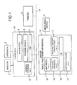
- Fig. 1 is a block diagram of an image processing apparatus according to an embodiment of the present invention.
- the image processing system is constructed by connecting a server 14 (image processing apparatus) and a client (personal computer (PC)) 13 to a printer 2 through a network such as a local area network (LAN) 17.
- the server 14 performs arithmetic operation.
- the client 13 interfaces with a user and the printer 2.
- the server 14 includes an arithmetic unit 10, a history storage unit 11, a feature amount converting unit 12, a profile updating unit 15, and an operating system (OS) 16.
- the server 14 is connected with a measuring device 5 for color patches.
- the feature amount converting unit 12 stores a first LUT 202 in advance.
- the arithmetic unit 10 compares previously measured values of a color chart in the history storage unit 11 with newly measured values of a color chart, and determines a number of color patches from the result of comparison.
- the history storage unit 11 stores measured values (L, a, b) 201 in Lab coordinate of the past color patches and vector values 203 obtained by compressing the three-dimensional Lab values 201 to one-dimensional values.
- This unit 11 corresponds to, for example, a hard disk drive (HDD) and a nonvolatile memory.
- the profile updating unit 15 allows the printer to output a color chart including the number of patches determined by the arithmetic unit 10, re-loads the chart, updates the printer profile, and transmits the updated profile to the client 13.
- the operating system (OS) 16 is, for example, Microsoft Windows, UNIX, and Linux.
- the feature amount converting unit 12 represents a converting unit in the present invention
- the arithmetic unit 10 represents an arithmetic unit in the present invention
- the profile updating unit 15 represents an updating unit in the present invention
- the history storage unit 11 represents a storage unit in the present invention.
- a program for generating a C language program executed on a C language program generating unit is recorded in a computer-readable recording medium and is provided.
- the recording medium includes a CD-ROM, floppy disk (FD), or DVD so that the program is recorded in the form of an installable format file or an executable format file.
- the program for generating the C language program may be stored on a computer connected to a network such as the Internet to be provided by allowing another computer to download it through the network.
- the program may be provided or distributed through the network.
- An image processing program operating on the server 14 of the embodiment is fetched from a recording medium and executed in the server 14 to load the program on a main storage device to thereby generate the feature amount converting unit 12, the arithmetic unit 10, and the profile updating unit 15 on the main storage device.
- the image processing program is recorded in CD-ROM, DVD-ROM, or FD in the form of an installable or executable file format, and is provided.
- Such an image processing program may be provided through a network and further be provided to the outside through the network in the file format.
- the client 13 includes an application 7, a profile storage unit 6, a printer driver 8, and an operating system (OS) 9.
- the client 13 is connected with a monitor 3 and an operator (operating unit) 4.
- the application 7 is, for example, a word processor or an application for performing spreadsheet calculation, and sends data such as a document created by the application 7 to the printer driver 8 using printing command.
- the printer driver 8 receives input color data (e.g., red (R), green (G), and blue (B)) from the application 7, converts the data to data in a format so that the printer 2 can interpret, and transmits the converted data.
- the data conversion is performed by referring to an N-dimensional LUT (N, number of dimensions of an input color space) in the profile stored in the profile storage unit 6 of the client 13.
- N-dimensional LUT is created in the server 14, and the profile includes the LUTs corresponding to a number of elements of output data.
- one of the LUTs is expressed by coordinates of L, a, and b represented by three-dimensional Lab values, i.e., a Lab color space.
- the OS 9 is, for example, Microsoft Windows, UNIX, and Linux.
- the profile storage unit 6 stores a printer profile received from the server 14, and an HDD or a nonvolatile memory serves as the unit 6.
- the server 14 and the client 13 are connected with a control device such as CPU, a recording device such as HDD, a storage device such as RAM and a nonvolatile memory, and a communication device such as a network board, which is an ordinary configuration using a computer.
- a control device such as CPU
- a recording device such as HDD
- a storage device such as RAM and a nonvolatile memory
- a communication device such as a network board, which is an ordinary configuration using a computer.
- the example shown in Fig. 1 has the server 14 and the client 13 as discrete units, but one unit of personal computer may include both of the functions.
- the structure may support a so-called meta frame environment such that the server 14 has the application and the printer driver 8 and the client 13 downloads the application and printer driver 8 only when using them.
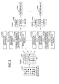
- Fig. 2A and Fig. 2B illustrate how to create data to be stored in the history storage unit 11 of the server 14.
- the history storage unit 11 stores measured values (L, a, b) 201 in Lab coordinate of the color patches of the past as shown in Fig. 2A.
- the measured values 201 of the past color patches are obtained by performing arithmetic on three-dimensional Lab values 201 as one-dimensionally compressed vector value 203 in the arithmetic unit 10 using the first LUT 202 in the feature amount converting unit 12, and the vector value is stored in the history storage unit 11.
- the first LUT 202 is a table prepared in advance, and is set as a reference, and therefore, this table is not possibly rewritten.
- the vector value 203 is used for determining Lab values at the time of creating patches.
- the number B of representative vectors becomes 2 c where c is a division number of space (a number of hierarchies in binary trees).
- a one-dimensional vector code value 2 (c-1) obtained by dividing the space by (c-1) times represents an average value of one-dimensional vector code values 2 c-1 and 2 c in a low hierarchy (divided by c times). Therefore, if the one-dimensional vector code value 2 (c-1) expresses a blue type color, a vector code value in the low hierarchy expresses a bluish green type color or a bluish purple type color.
- each distance (or color difference) between Lab values 211 obtained by measuring output color patches 210 and Lab values of reference white (e.g., paper white) of a medium for printing is obtained.
- a distance 212 as ⁇ E76 (“ ⁇ E76 distance") is calculated by the color difference formula according to the ClE1976Lab color system (CIE, Commission Internationale de L'Eclairage, International Commission on Illumination), and a distance 213 as ⁇ E94 (" ⁇ E94 distance”) is calculated by the CIE1994 color difference formula.
- a difference (“distance between color differences") 214 between the ⁇ E76 distance and the ⁇ E94 distance is obtained to allow detailed characteristics of a target color to be acquired in a numerical form.
- an N-dimensional input vector is converted to a one-dimensional vector value 216 using a second conversion table LUT 215 in the feature amount converting unit 12.
- the first and second LUTs 202 and 215 are prepared by using a large amount of sample data when the system is constructed, and include codes indicating values at lattice points and vector values representing the codes.
- the number of one-dimensional representative vectors is a number of lattice points in an N-dimensional cube in the profile. Assuming the number of division of a color to be presented is n, the number of representative vectors is n 3 .
- the first LUT 202 is used also for creating the profile, the number of representative vectors stands at n 3 .
- the second LUT 215 prepare representative vectors created with a smaller number than n 3 (e.g., (n/2) 3 , (n/4) 3 ).
- a third LUT 217 (217a ⁇ 217m) uses vectors after the vectors are expressed as neighborhoods of representative colors using the first LUT 202 as shown in Fig. 3.
- N the number of elements in the LUT
- vector values 218a. . . 218m are obtained for L units of elements as shown in the LUT 217, thus, achieving high precision. That is, the third LUTs 217a ... 217m are prepared in advance for lattice points near the representative colors, and any of the processing 211 a, 212a, 213a, 214a, ...
- 211m, 212m, 213m, and 214m corresponding to neighbor colors of the representative color is executed without executing the processing to all the neighbor colors of the representative colors as shown in Fig. 2B, and conversion may be performed using any of the LUTs 217a through 217m corresponding to the processing. Therefore, the processing load becomes lighter to obtain high speed processing. Further, as the range of colors is narrowed, correction with higher precision becomes possible.
- Fig. 4 is a flowchart of creating a color chart (patches) in which a number of color patches and a color region are optimized.
- a color chart as a reference for optimizing the number of patches is output from the printer 2 (step S1), Lab values of the color patches 210 in the color chart are measured by a measuring device 5 (step S2). At this time, the number of patches in the color chart is set to the same or a smaller number of representative vectors in the LUT 202.
- the ⁇ E76 distance 212, the ⁇ E94 distance 213, and the distance 214 between the color differences are obtained by the arithmetic unit 10 to combine them as a vector (step S3).
- step S4 When an instruction to measure only a representative color (e.g., R, G, B, C M, Y) is received from the user (step S4, Yes), the most recently measured results are loaded from the history storage unit 11 to extract a plurality pieces of data close to the representative vector indicating the representative color from any of the third LUTs 217a to 217m.
- a representative color e.g., R, G, B, C M, Y
- an N-dimensional vector is converted to a one-dimensional vector based on the second LUT 215, and the one-dimensional vector is stored in the history storage unit 11. If no instruction is received from the user (step S4, No), the N-dimensional vector is converted to the one-dimensional vector for the whole pieces of data corresponding to the whole color regions constituting the most recently updated profile, based on the second LUT 215, and the one-dimensional vectors are stored in the history storage unit 11.
- an error is compared with an error (“A2") (step S5).
- the error A1 is between the vector of the previously measured result and the vector of the newly measured result
- the error A2 is between the representative vector indicating an average value of measured values and the vector of the newly measured result.
- A1 is the evaluation standard including short-term characteristics of the printer based on the values measured last time and this time
- A2 is the evaluation standard including long-term characteristics of the printer based on the average value of a large amount of samples and the value measured this time.
- the condition for this time is preferentially selected, and lack of data is covered by extracting the data from the history storage unit 11 to obtain the error.
- the target Lab values are stored for patch creation (step S8).
- the Lab values for the patch creation are obtained by use of backward reference to the first LUT 201 to change the Lab values according to an Ev value, patches are randomly created and arranged in a color chart, and then the color chart is output from the printer 2 to measure again the patches (step S8 ⁇ step S1).
- the position of forming the color patches is set on the side closer to the edge part of the photoreceptor if the Ev value is small, and is set on the side closer to the central part thereof if it is great. Consequently, the position of forming the color patches can be set according to the Ev value, and a combination of the setting of the position and the change in the number of color patches is highly adaptable to any of the changes.
- the number of patches to be created is determined at a point in time when the number of patches becomes smaller than a threshold value ⁇ 2 of patches (step S9).
- a profile creating unit creates a profile by weighting the evaluation-standard value Ev.
- the threshold value ⁇ 2 is set by the user or set based on the threshold value ⁇ 1 for determination on the patch output.
- the server 14, the client 13, and the printer 2 form the image processing system as shown in Fig. 1.
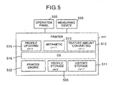
- a profile updating unit 515, an arithmetic unit 510, a feature amount converting unit 512, an OS 516, a profile storage unit 506, a history storage unit 511, and a printer engine 502 that executes printing can be formed as one unit, or can be formed as one printer 500 (image forming apparatus) by accommodating the components in one casing.
- the profile updating unit 515, arithmetic unit 510, feature amount converting unit 512, profile storage unit 506, and the history storage unit 511 have the same functions as those in the units shown in Fig. 1.
- the printer 500 is connected with an operation panel 503 and a measuring device 505.
- a printer driver 608 of PC 613 may include a profile updating unit 615, an arithmetic unit 610, and a feature amount converting unit 612. Further, an HDD or a nonvolatile memory may include a profile storage unit 606 and a history storage unit 611.
- an error at the time of compressing information is obtained based on the history information and representative vector and the new information to determine the error as an evaluation standard. It is, thereby, possible to control the number of patches of the color chart and create a printer profile with high precision.
- the printer profile includes short-term characteristics of the printer such as characteristics obtained by detecting the number of positions of the color patches, and long-term characteristics such as history information stored in the history storage. Further, the color region is divided based on Lab distances as a reference to enable selection of a quantitative representative color, and creation and correction of the profile according to the user's purpose.
Landscapes
- Engineering & Computer Science (AREA)
- Multimedia (AREA)
- Signal Processing (AREA)
- Facsimile Image Signal Circuits (AREA)
- Color Image Communication Systems (AREA)
- Image Processing (AREA)
- Color, Gradation (AREA)
- Accessory Devices And Overall Control Thereof (AREA)
Abstract
Description
Claims (32)
- An image processing apparatus comprising:a converting unit (12) that performs color conversion of input data, wherein the input data is color data obtained from measurement of a color chart of an image;a storage unit (11) that stores the conversion data and history information on the measurement of the color chart;an arithmetic unit (10) that compares the history information with information on the measurement of the color chart to determine number of color patches; andan updating unit (15) that updates the printer profile based on the number of color patches.
- An image processing apparatus according to claim 1, wherein the information on the measurement of the color chart includes the color data, number of times of the measurement, and color regions at the time of the measurement.
- An image processing apparatus according to either claim 1 or claim 2, wherein the converting unit (12) includes a table (202) for converting multi-dimensional Lab values into one-dimensional vector values.
- An image processing apparatus according to any one of claims 1 to 3, wherein the arithmetic unit (10) determines the number of color patches based on an evaluation standard, wherein the evaluation standard includes a newly measured patch value and an average of patch values previously measured and stored as the history information.
- An image processing apparatus according to any one of claims 1 to 3, wherein the arithmetic unit (10) determines the number of color patches based on an evaluation standard, wherein the evaluation standard includes a newly measured patch value and a patch value measured last time and stored as the history information.
- An image processing apparatus according to any one of the preceding claims, wherein
the arithmetic unit (10) compares a first difference with a second difference, wherein
the first difference is a difference between a newly measured patch value and a patch value measured last time and stored as the history information, and
the second difference is a difference between the newly measured patch value and an average value of the patch values previously measured and stored as the history information, and
when the first difference is equal to or greater than the second difference, the arithmetic unit determines the number of color patches based on a third difference, wherein the third difference is a difference between the newly measured patch value and a patch value measured last but one. - An image processing apparatus according to any one of claims 1 to 5, wherein
the arithmetic unit (10) compares a first difference with a second difference, wherein
the first difference is a difference between a newly measured patch value and a patch value measured last time and stored as the history information, and
the second difference is a difference between the newly measured patch value and an average value of the patch values previously measured and stored as the history information, and
when the first difference is less than the second difference, the arithmetic unit determines the number of color patches based on a third difference, wherein the third difference is a difference between the newly measured patch value and a measured patch value having a minimum difference from a representative vector indicating a representative color. - An image processing apparatus according to any one of claims 4, 6 or 7, wherein the evaluation standard is a predetermined value obtained for each neighborhood of Whole color regions that constitute a profile.
- An image processing apparatus according to claim 8, wherein the evaluation standard is a value obtained by combining a first distance, a second distance, and a third distance obtained for each neighborhood of the whole color regions, wherein
the first distance is a distance between Lab values obtained from measuring the color patch and Lab values obtained from a reference white of an output medium, based on a color difference formula according to ClE1976Lab color system,
the second distance is a distance between the Lab values obtained from measuring the color patch and the Lab values obtained from the reference white, based on a color difference formula according to ClE1994 color difference system, and
the third distance is a difference between the first distance and the second distance. - An image processing apparatus according to any one of claims 4, 6 or 7, wherein the evaluation standard is a predetermined value obtained for each neighborhood of representative colors including preset colors that constitute a profile.
- An image processing apparatus according to claim 10, wherein the evaluation standard is a value obtained by combining a first distance, a second distance, and a third distance obtained for each neighborhood of the representative colors, wherein
the first distance is a distance between Lab values obtained from measuring the color patch and Lab values obtained from a reference white of an output medium, based on a color difference formula according to ClE1976Lab color system,
the second distance is a distance between the Lab values obtained from measuring the color patch and the Lab values obtained from the reference white, based on a color difference formula according to ClE1994 color difference system, and
the third distance is a difference between the first distance and the second distance. - An image processing apparatus according to either claim 10 or claim 11, wherein the representative colors are red, green, black, cyan, magenta, and yellow.
- An image processing apparatus according to any one of claims 9 to 12, further comprising a compressing unit that compresses the combined value.
- An image processing apparatus according to claim 13, wherein the compressing unit compresses the combined value by vector quantization.
- An image processing apparatus according to either claim 13 or claim 14, wherein the storage unit (11 ) stores the compressed value.
- The image processing apparatus according to any one of claims 13 to 15, wherein the evaluation standard includes a reference vector for the compression of the combined value and an error occurring when the combined value is compressed.
- An image processing system comprising:a server (14) that updates a printer profile based on color data obtained from measurement of a color chart of an image; anda client (13) that is connected to the server, whereinthe server includes
a converting unit (12) that performs color conversion of the color data to produce conversion data;
a storage unit (11 ) that stores the conversion data and history information on the measurement of the color chart;
an arithmetic unit (10) that compares the history information with information on the measurement of the color chart to determine number of color patches; and
an updating unit (15) that updates the printer profile based on the number of color patches, andthe client (13) includes
a profile storage unit (6) that stores a printer profile created by the server (14); and
a printer driver (8) that converts input color data received from an application (7) into output color data that can be interpreted by an image forming apparatus. - An image processing system according to claim 17, further comprising a measuring unit (5) that measures the color chart to obtain Lab values, and outputs the Lab values to the client (13).
- An image forming apparatus (500) comprising:a converting unit (512) that performs color conversion of input data, wherein the input data is color data obtained from measurement of a color chart of an image;a storage unit (511) that stores the conversion data and history information on the measurement of the color chart;an arithmetic unit (510) that compares the history information with information on the measurement of the color chart to determine number of color patches;a profile storage unit (506) that stores a printer profile;an updating unit (515) that updates the printer profile based on the number of color patches; andan image forming unit (502) that forms a visible image on a medium.
- A method of image processing comprising:performing color conversion of input data, wherein the input data is color data obtained from measurement of a color chart of an image;storing the conversion data and history information on the measurement of the color chart;comparing the history information with information on the measurement of the color chart to determine number of color patches; andupdating the printer profile based on the number of color patches.
- A method according to claim 20, wherein the number of color patches is determined based on an evaluation standard, wherein the evaluation standard includes a newly measured patch value and an average of patch values previously measured and stored as the history information,
- A method according to claim 20, wherein the number of color patches is determined based on an evaluation standard, wherein the evaluation standard includes a newly measured patch value and a patch value measured last time and stored as the history information.
- A method according to any one of claims 20 to 22, wherein the comparing includes
comparing a first difference with a second difference, wherein
the first difference is a difference between a newly measured patch value and a patch value measured last time and stored as the history information, and
the second difference is a difference between the newly measured patch value and an average value of the patch values previously measured and stored as the history information; and
determining the number of color patches based on a third difference, when the first difference is equal to or greater than the second difference, wherein the third difference is a difference between the newly measured patch value and a patch value measured last but one. - A method according to any one of claims 20 to 22, wherein the comparing includes
comparing a first difference with a second difference, wherein
the first difference is a difference between a newly measured patch value and a patch value measured last time and stored as the history information, and
the second difference is a difference between the newly measured patch value and an average value of the patch values previously measured and stored as the history information; and
determining the number of color patches based on a third difference, when the first difference is less. than the second difference, wherein the third difference is a difference between the newly measured patch value and a measured patch value having a minimum difference from a representative vector indicating a representative color. - A method according to any one of claims 21, 23 or 24, wherein the evaluation standard is a predetermined value obtained for each neighborhood of whole color regions that constitute a profile.
- A method according to claim 25, wherein the evaluation standard is a value obtained by combining a first distance, a second distance, and a third distance obtained for each neighborhood of the whole color regions, wherein
the first distance is a distance between Lab values obtained from measuring the color patch and Lab values obtained from a reference white of an output medium, based on a color difference formula according to ClE1976Lab color system,
the second distance is a distance between the Lab values obtained from measuring the color patch and the Lab values obtained from the reference white, based on a color difference formula according to CIE 1994 color difference system, and
the third distance is a difference between the first distance and the second distance. - A method according to any one of claims 21, 23 or 24, wherein the evaluation standard is a predetermined value obtained for each neighborhood of representative colors including preset colors that constitute a profile.
- The method according to claim 27, wherein the evaluation standard is a value obtained by combining a first distance, a second distance, and a third distance obtained for each neighborhood of the representative colors, wherein
the first distance is a distance between Lab values obtained from measuring the color patch and Lab values obtained from a reference white of an output medium, based on a color difference formula according to CIE1976Lab color system,
the second distance is a distance between the Lab values obtained from measuring the color patch and the Lab values obtained from the reference white, based on a color difference formula according to ClE1994 color difference system, and
the third distance is a difference between the first distance and the second distance. - A method according to either claim 27 or claim 28, further comprising compressing the combined value.
- A method according to claim 29, wherein the evaluation standard includes a reference vector for the compression of the combined value and an error occurring when the combined value is compressed.
- A computer program comprising program code means that, when executed on a computer system, instruct a computer system to carry out the steps according to any one of claims 20 to 30.
- A computer readable storage medium having recorded thereon program code components that, when executed on a computer system, instruct a computer system to carry out the steps according to any one of claims 20 to 30.
Applications Claiming Priority (4)
| Application Number | Priority Date | Filing Date | Title |
|---|---|---|---|
| JP2002275934 | 2002-09-20 | ||
| JP2002275934 | 2002-09-20 | ||
| JP2003317404A JP2004135312A (en) | 2002-09-20 | 2003-09-09 | Image processing apparatus, image processing system, image forming apparatus, image processing method, and program |
| JP2003317404 | 2003-09-09 |
Publications (2)
| Publication Number | Publication Date |
|---|---|
| EP1401192A2 true EP1401192A2 (en) | 2004-03-24 |
| EP1401192A3 EP1401192A3 (en) | 2005-10-05 |
Family
ID=31949606
Family Applications (1)
| Application Number | Title | Priority Date | Filing Date |
|---|---|---|---|
| EP03255893A Withdrawn EP1401192A3 (en) | 2002-09-20 | 2003-09-19 | Creating and updating a printer profile |
Country Status (3)
| Country | Link |
|---|---|
| US (1) | US7403305B2 (en) |
| EP (1) | EP1401192A3 (en) |
| JP (1) | JP2004135312A (en) |
Cited By (2)
| Publication number | Priority date | Publication date | Assignee | Title |
|---|---|---|---|---|
| WO2006101811A1 (en) * | 2005-03-22 | 2006-09-28 | Eastman Kodak Company | Method for monitoring image calibration |
| WO2011057725A1 (en) * | 2009-11-10 | 2011-05-19 | Manroland Ag | Method for controlling a printing process |
Families Citing this family (16)
| Publication number | Priority date | Publication date | Assignee | Title |
|---|---|---|---|---|
| DE10246253A1 (en) * | 2002-10-02 | 2004-04-22 | Cgs Publishing Technologies International Gmbh | Method for creating a color match between a target object and a source object |
| JP4059873B2 (en) * | 2004-09-22 | 2008-03-12 | シャープ株式会社 | Image processing device |
| JP2009194553A (en) * | 2008-02-13 | 2009-08-27 | Seiko Epson Corp | How to determine the number of patches |
| JP2009194552A (en) * | 2008-02-13 | 2009-08-27 | Seiko Epson Corp | Patch number determination method, calibration method, and printing apparatus |
| JP5132428B2 (en) * | 2008-05-28 | 2013-01-30 | キヤノン株式会社 | Information processing apparatus, method, and program |
| JP5257615B2 (en) * | 2009-06-04 | 2013-08-07 | 株式会社リコー | Color conversion table generation apparatus, color conversion table generation method, and image processing apparatus |
| JP2011077844A (en) * | 2009-09-30 | 2011-04-14 | Seiko Epson Corp | Printing apparatus, and calibration method |
| JP5909928B2 (en) | 2010-09-16 | 2016-04-27 | 株式会社リコー | Image forming apparatus, image forming method, and program |
| US8576418B2 (en) * | 2010-12-13 | 2013-11-05 | Xerox Corporation | Method for dynamic optimization of refinement patches for color printer characterization |
| JP5948737B2 (en) | 2011-05-30 | 2016-07-06 | 株式会社リコー | Image processing apparatus, image processing method, and image processing program |
| US20150070512A1 (en) * | 2013-09-06 | 2015-03-12 | Ferrand D.E. Corley | Test pattern and method of monitoring changes in test pattern characteristics |
| JP6098587B2 (en) * | 2014-08-06 | 2017-03-22 | コニカミノルタ株式会社 | Printing control apparatus, printing system, color adjustment control program, and color adjustment control method |
| US9686445B2 (en) * | 2015-09-30 | 2017-06-20 | Konica Minolta Laboratory U.S.A., Inc. | Method and system for dynamically producing color validation patches |
| JP7632156B2 (en) * | 2021-07-30 | 2025-02-19 | 株式会社リコー | Image forming apparatus, program, and image forming method |
| JP7771640B2 (en) | 2021-11-08 | 2025-11-18 | 株式会社リコー | Information processing device, image forming system, information processing method and program |
| JP7793947B2 (en) | 2021-11-09 | 2026-01-06 | 株式会社リコー | Information processing device, image forming system, information processing method and program |
Family Cites Families (15)
| Publication number | Priority date | Publication date | Assignee | Title |
|---|---|---|---|---|
| US5107332A (en) | 1989-05-17 | 1992-04-21 | Hewlett-Packard Company | Method and system for providing closed loop color control between a scanned color image and the output of a color printer |
| US5781206A (en) * | 1995-05-01 | 1998-07-14 | Minnesota Mining And Manufacturing Company | Apparatus and method for recalibrating a multi-color imaging system |
| US5739927A (en) * | 1995-06-07 | 1998-04-14 | Xerox Corporation | Method for refining an existing printer calibration using a small number of measurements |
| JP3869925B2 (en) * | 1997-01-31 | 2007-01-17 | キヤノン株式会社 | Image processing apparatus and method |
| US6178007B1 (en) * | 1997-01-21 | 2001-01-23 | Xerox Corporation | Method for continuous incremental color calibration for color document output terminals |
| US6048117A (en) * | 1998-05-08 | 2000-04-11 | Xerox Corporation | Network-based system for color calibration of printers |
| JP2000004369A (en) | 1998-06-15 | 2000-01-07 | Ricoh Co Ltd | Image processing method, image processing apparatus, and recording medium |
| US6870636B2 (en) * | 1998-11-20 | 2005-03-22 | Canon Kabushiki Kaisha | Determining color mappings for a color printer |
| US6233061B1 (en) * | 1999-02-11 | 2001-05-15 | Lexmark International, Inc. | Ink reduction device and method for a color inkjet printer |
| JP2000318266A (en) * | 1999-05-12 | 2000-11-21 | Canon Inc | Calibration method, information processing device and information processing system |
| JP2001045313A (en) | 1999-07-30 | 2001-02-16 | Fuji Photo Film Co Ltd | Method and device for converting color, color conversion program storage medium and method for correcting color |
| JP3910323B2 (en) | 1999-11-11 | 2007-04-25 | 富士フイルム株式会社 | Profile creation method and profile creation apparatus |
| US7064860B1 (en) * | 2000-05-15 | 2006-06-20 | Xerox Corporation | Color-balanced TRC correction to compensate for illuminant changes in printer characterization |
| US7003151B2 (en) * | 2000-07-19 | 2006-02-21 | Canon Kabushiki Kaisha | Image processing apparatus and control method therefor |
| JP2002187314A (en) * | 2000-09-12 | 2002-07-02 | Canon Inc | Image processing apparatus and method, prediction method, display method, and management method |
-
2003
- 2003-09-09 JP JP2003317404A patent/JP2004135312A/en active Pending
- 2003-09-15 US US10/662,667 patent/US7403305B2/en not_active Expired - Fee Related
- 2003-09-19 EP EP03255893A patent/EP1401192A3/en not_active Withdrawn
Cited By (4)
| Publication number | Priority date | Publication date | Assignee | Title |
|---|---|---|---|---|
| WO2006101811A1 (en) * | 2005-03-22 | 2006-09-28 | Eastman Kodak Company | Method for monitoring image calibration |
| US7310107B2 (en) | 2005-03-22 | 2007-12-18 | Eastman Kodak Company | Method for monitoring image calibration |
| WO2011057725A1 (en) * | 2009-11-10 | 2011-05-19 | Manroland Ag | Method for controlling a printing process |
| US9774763B2 (en) | 2009-11-10 | 2017-09-26 | Manroland Web Systems Gmbh | Method for controlling a printing process |
Also Published As
| Publication number | Publication date |
|---|---|
| US20040114165A1 (en) | 2004-06-17 |
| EP1401192A3 (en) | 2005-10-05 |
| US7403305B2 (en) | 2008-07-22 |
| JP2004135312A (en) | 2004-04-30 |
Similar Documents
| Publication | Publication Date | Title |
|---|---|---|
| US7403305B2 (en) | Image processing system, apparatus and method for updating a printer profile based on comparison of previous and current measurements of color chart | |
| US7054033B2 (en) | Image processing method, image processing apparatus, and storage medium | |
| JP4623137B2 (en) | Color processing apparatus, method and program | |
| US8290259B2 (en) | Device adaptively switching color emphasis processing for image | |
| US7764411B2 (en) | Color processing apparatus and method, and storage medium storing color processing program | |
| US8786626B2 (en) | Color processing device, color processing method, and computer readable medium storing program | |
| US9846826B2 (en) | Image processing to generate a tone curve for processing an image by associating a model parameter of the image with another model parameter of a reference image | |
| CN100583945C (en) | Image processing apparatus, image processing method | |
| EP2965499B1 (en) | Image processing apparatus, image processing system, and image processing method | |
| JP2003331276A (en) | Color conversion definition correcting device and program | |
| EP3474531B1 (en) | Device link profile adjustment method, device link profile adjustment apparatus, and device link profile creation method | |
| US6337923B1 (en) | Color correction apparatus for minimizing metamerism of color scanner and method therefor | |
| JP2009278264A (en) | Color processing apparatus, and program | |
| JP2009177415A (en) | Conversion table creation device, conversion table creation program, and conversion table creation method | |
| JP2003125224A (en) | Profile adjustment apparatus and method | |
| US20060082843A1 (en) | Method and system for calibration and characterization of joint nonlinear and linear transformations for a color input or output device | |
| JP2005311900A (en) | Image processing apparatus and its method | |
| US8437541B2 (en) | Color correction coefficient generating apparatus, color correction coefficient generation method, and computer readable medium storing program | |
| JP4379009B2 (en) | Method for creating input profile and computer program | |
| JPH08111784A (en) | Color image processor | |
| JP4757081B2 (en) | Image processing method and apparatus | |
| JP2004236200A (en) | Color processing parameter editing method and color processing parameter editing apparatus | |
| JP2008067308A (en) | Color processing device, color processing method, and program | |
| JP2006013608A (en) | Color transformation definition correcting device and program | |
| JP2004120588A (en) | Color control method between multiple devices |
Legal Events
| Date | Code | Title | Description |
|---|---|---|---|
| PUAI | Public reference made under article 153(3) epc to a published international application that has entered the european phase |
Free format text: ORIGINAL CODE: 0009012 |
|
| 17P | Request for examination filed |
Effective date: 20030930 |
|
| AK | Designated contracting states |
Kind code of ref document: A2 Designated state(s): AT BE BG CH CY CZ DE DK EE ES FI FR GB GR HU IE IT LI LU MC NL PT RO SE SI SK TR |
|
| AX | Request for extension of the european patent |
Extension state: AL LT LV MK |
|
| PUAL | Search report despatched |
Free format text: ORIGINAL CODE: 0009013 |
|
| AK | Designated contracting states |
Kind code of ref document: A3 Designated state(s): AT BE BG CH CY CZ DE DK EE ES FI FR GB GR HU IE IT LI LU MC NL PT RO SE SI SK TR |
|
| AX | Request for extension of the european patent |
Extension state: AL LT LV MK |
|
| RAP1 | Party data changed (applicant data changed or rights of an application transferred) |
Owner name: RICOH COMPANY, LTD. |
|
| AKX | Designation fees paid |
Designated state(s): DE ES FR GB IT NL |
|
| 17Q | First examination report despatched |
Effective date: 20060630 |
|
| STAA | Information on the status of an ep patent application or granted ep patent |
Free format text: STATUS: THE APPLICATION HAS BEEN WITHDRAWN |
|
| 18W | Application withdrawn |
Effective date: 20090525 |