EP1401122A2 - Orthogonal frequency division multiplexing receiver - Google Patents
Orthogonal frequency division multiplexing receiver Download PDFInfo
- Publication number
- EP1401122A2 EP1401122A2 EP03255645A EP03255645A EP1401122A2 EP 1401122 A2 EP1401122 A2 EP 1401122A2 EP 03255645 A EP03255645 A EP 03255645A EP 03255645 A EP03255645 A EP 03255645A EP 1401122 A2 EP1401122 A2 EP 1401122A2
- Authority
- EP
- European Patent Office
- Prior art keywords
- phase shifter
- base band
- antenna
- ofdm
- frequency signal
- Prior art date
- Legal status (The legal status is an assumption and is not a legal conclusion. Google has not performed a legal analysis and makes no representation as to the accuracy of the status listed.)
- Withdrawn
Links
- 238000010276 construction Methods 0.000 description 23
- 230000015572 biosynthetic process Effects 0.000 description 12
- 238000003786 synthesis reaction Methods 0.000 description 12
- 238000010586 diagram Methods 0.000 description 4
- 230000009466 transformation Effects 0.000 description 2
- 238000006243 chemical reaction Methods 0.000 description 1
- 230000000694 effects Effects 0.000 description 1
- 238000005562 fading Methods 0.000 description 1
Images
Classifications
-
- H—ELECTRICITY
- H04—ELECTRIC COMMUNICATION TECHNIQUE
- H04B—TRANSMISSION
- H04B7/00—Radio transmission systems, i.e. using radiation field
- H04B7/02—Diversity systems; Multi-antenna system, i.e. transmission or reception using multiple antennas
- H04B7/04—Diversity systems; Multi-antenna system, i.e. transmission or reception using multiple antennas using two or more spaced independent antennas
- H04B7/08—Diversity systems; Multi-antenna system, i.e. transmission or reception using multiple antennas using two or more spaced independent antennas at the receiving station
- H04B7/0837—Diversity systems; Multi-antenna system, i.e. transmission or reception using multiple antennas using two or more spaced independent antennas at the receiving station using pre-detection combining
- H04B7/084—Equal gain combining, only phase adjustments
-
- H—ELECTRICITY
- H04—ELECTRIC COMMUNICATION TECHNIQUE
- H04L—TRANSMISSION OF DIGITAL INFORMATION, e.g. TELEGRAPHIC COMMUNICATION
- H04L27/00—Modulated-carrier systems
- H04L27/26—Systems using multi-frequency codes
- H04L27/2601—Multicarrier modulation systems
- H04L27/2647—Arrangements specific to the receiver only
-
- H—ELECTRICITY
- H04—ELECTRIC COMMUNICATION TECHNIQUE
- H04B—TRANSMISSION
- H04B7/00—Radio transmission systems, i.e. using radiation field
- H04B7/02—Diversity systems; Multi-antenna system, i.e. transmission or reception using multiple antennas
- H04B7/04—Diversity systems; Multi-antenna system, i.e. transmission or reception using multiple antennas using two or more spaced independent antennas
- H04B7/08—Diversity systems; Multi-antenna system, i.e. transmission or reception using multiple antennas using two or more spaced independent antennas at the receiving station
- H04B7/0868—Hybrid systems, i.e. switching and combining
- H04B7/0874—Hybrid systems, i.e. switching and combining using subgroups of receive antennas
-
- H—ELECTRICITY
- H04—ELECTRIC COMMUNICATION TECHNIQUE
- H04B—TRANSMISSION
- H04B7/00—Radio transmission systems, i.e. using radiation field
- H04B7/02—Diversity systems; Multi-antenna system, i.e. transmission or reception using multiple antennas
- H04B7/04—Diversity systems; Multi-antenna system, i.e. transmission or reception using multiple antennas using two or more spaced independent antennas
- H04B7/08—Diversity systems; Multi-antenna system, i.e. transmission or reception using multiple antennas using two or more spaced independent antennas at the receiving station
- H04B7/0891—Space-time diversity
- H04B7/0894—Space-time diversity using different delays between antennas
-
- H—ELECTRICITY
- H04—ELECTRIC COMMUNICATION TECHNIQUE
- H04L—TRANSMISSION OF DIGITAL INFORMATION, e.g. TELEGRAPHIC COMMUNICATION
- H04L1/00—Arrangements for detecting or preventing errors in the information received
- H04L1/004—Arrangements for detecting or preventing errors in the information received by using forward error control
Definitions
- This invention relates to an OFDM receiver for receiving an OFDM (Orthogonal Frequency Division Multiplexing) modulated high frequency signal by diversity synthesis, and particularly relates to an OFDM receiver suitably used in a television receiver for car mounting.
- OFDM Orthogonal Frequency Division Multiplexing
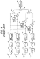
- Fig. 4 shows a conventional OFDM receiver.
- plural antennas shown in the case of four antennas
- 111, 121, 131, 141 for receiving an OFDM modulated high frequency signal are arranged in places separated from each other on a vehicle as one example.
- Receiving portions 112, 122, 132, 142 are correspondingly connected to the respective antennas 111 to 141.
- the respective receiving portions 112 to 142 have the same construction, and frequency-convert the high frequency signal to be received to an intermediate frequency signal.
- A/D converters 113, 123, 133, 143 are connected to the next stages of the respective receiving portions 112 to 142.
- Each A/D converter converts the intermediate frequency signal to a digital signal, and outputs a base band signal of a time area.
- First to fourth OFDM demodulating means 11 4, 124, 134, 144 are connected to the next stages of the respective A/D converters 113 to 143.
- the respective OFDM demodulating means 114 to 144 have a high speed Fourier converter of the same construction therein, and perform conversion to the base band signal of a frequency area by performing Fourier transformation by taking synchronization of the base band signal of the time area.
- a first phase control circuit 151 is connected between the output terminal of the first OFDM demodulating means 114 and the output terminal of the second OFDM demodulating means 124 among the above four OFDM demodulating means.
- a second phase control means 152 is connected between the output terminal of the first OFDM demodulating means 114 and the output terminal of the third OFDM demodulating means 134.
- a third phase control means 153 is connected between the output terminal of the first OFDM demodulating means 114 and the output terminal of the fourth OFDM demodulating means 144.
- a first phase shifter 154, a second phase shifter 155 and a third phase shifter 156 are respectively connected to the next stages of the second to fourth OFDM demodulating means.
- the respective phase control means 151 to 153 have the same construction, and respectively compare the phase of the base band signal of the frequency area outputted from the second to fourth OFDM demodulating means 124, 134, 144 and the phase of the base band signal of the frequency area outputted from the first OFDM demodulating means 114, and respectively output its phase difference signals to the first to third phase shifters 154 to 156.
- Each of the phase shifters 154 to 156 outputs a base band signal of the frequency area conformed to the phase of the base band signal of the frequency area outputted from the first OFDM demodulating means 114 by changing the phase of the inputted base band signal of the frequency area by each phase difference signal.
- the base band signal of the frequency area outputted from the first OFDM demodulating means 114 and the base band signal of the frequency area outputted from the first phase shifter 154 are added by a first adder 157.
- the base band signal of the frequency area outputted from the second phase shifter 155 and the base band signal of the frequency area outputted from the third phase shifter 156 are added by a second adder 158.
- a third adder 159 is connected between the output terminal of the first adder 157 and the output terminal of the second adder 158. Accordingly, the base band signals of the frequency area outputted from all the OFDM demodulating means 114 to 144 are finally added by the third adder 159 in the same phase relation. Accordingly, a base band signal having maximum signal electric power is obtained from the third adder 159.
- a bit error included in the added base band signal is corrected by an error correcting means 160, and the corrected base band signal of the frequency area is outputted.
- the expensive OFDM demodulating means is arranged by the same number correspondingly with each antenna, it has a disadvantage in that the receiver is high in cost.
- An object of the present invention is to reduce cost by reducing the number of OFDM demodulating means, and easily synchronize the base band signal of the time area in the OFDM demodulating means.
- the base band signal of the time area based on the high frequency signal received by a specific antenna in each of the antenna groups, and the base band signal of the time area based on the high frequency signal received by another antenna except for the specific antenna are diversity-synthesized by the first phase shifter.
- a receiving portion for frequency-converting the high frequency signal to an intermediate frequency signal, and an A/D converter for converting the intermediate frequency signal to a digital signal and outputting the base band signal of the time area are arranged every each of the antennas, and the first phase shifter is arranged at the next stage of the A/D converter corresponding to the another antenna, and a first adder is arranged between the first phase shifter and the A/D converter corresponding to the specific antenna.
- the intermediate frequency signal based on the high frequency signal received by the specific antenna in each of the antenna groups, and the intermediate frequency signal based on the high frequency signal received by another antenna except for the specific antenna are diversity-synthesized by the first phase shifter.
- a receiving portion for frequency-converting the high frequency signal to the intermediate frequency signal is arranged every each of the antennas, and the first phase shifter is arranged at the next stage of the receiving portion corresponding to the another antenna, and a first adder is arranged between the receiving portion corresponding to the specific antenna and the first phase shifter.
- the high frequency signal received by the specific antenna in each of the antenna groups, and the high frequency signal received by another antenna except for the specific antenna are diversity-synthesized by the first phase shifter.
- the first phase shifter is connected to the another antenna, and a first adder is arranged between the specific antenna and the first phase shifter.
- power detecting means for detecting electric power of the base band signal of the time area, and phase control means for controlling phase setting of the first phase shifter so as to maximize the electric power are arranged.
- the second phase shifter is arranged at the next stage of the another OFDM demodulating means, and a second adder is arranged between the specific OFDM demodulating means and the second phase shifter.
- the OFDM receiver further comprises phase control means for controlling phase setting of the second phase shifter such that the phase of the base band signal of the frequency area outputted from the second phase shifter is conformed to the phase of the base band signal of the frequency area outputted from the specific OFDM demodulating means.
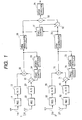
- Fig. 1 shows the construction of a first embodiment mode.
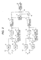
- Fig. 2 shows the construction of a second embodiment mode.
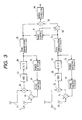
- Fig. 3 shows the construction of a third embodiment mode.
- antennas 11 and 21 and antennas 51 and 61 belong to separate antenna groups.
- a receiving portion 12 and an A/D converter 13 are sequentially cascade-connected to one specific antenna 11 in a first antenna group 1.
- a receiving portion 22, an A/D converter 23 and a first phase shifter 31 are sequentially cascade-connected to another antenna 21 except for the specific antenna 11.
- a first adder 32 is connected to the output terminal of the A/D converter 13 and the output terminal of the first phase shifter 31.
- the specific antenna 11 is distinguished from another antenna 21 because no first phase shifter 31 is interposed between the first adder 32 and the A/D converter 13 corresponding to the specific antenna 11.
- a power detecting means 33 and one specific OFDM demodulating means 35 are connected to the next stage of the first adder 32.
- a phase control means 34 is connected between the power detecting means 33 and the first phase shifter 31.
- a receiving portion 52 and an A/D converter 53 are sequentially cascade-connected to one specific antenna 51 in a second antenna group 5.
- a receiving portion 62, an A/D converter 63 and a first phase adder 71 are sequentially cascade-connected to another antenna 61 except for the specific antenna 51.
- a first adder 72 is connected to the output terminal of the A/D converter 53 and the output terminal of the first phase shifter 71.
- the specific antenna 51 is distinguished from another antenna 61 because no first phase shifter 71 is interposed between the first adder 72 and the A/D converter 53 corresponding to the specific antenna 51.
- a power detecting means 73 and another OFDM demodulating means 75 except for the specific OFDM demodulating means 35 are connected to the next stage of the first adder 72.
- a phase control means 74 is connected between the power detecting means 73 and the first phase shifter 71.
- a third adder 93 is connected to the next stage of the specific OFDM demodulating means 35.
- a second phase shifter 92 is connected to the next stage of another OFDM demodulating means 75.
- a third adder 93 is connected to the next stage of the second phase shifter 92.
- the specific OFDM demodulating means 35 is distinguished from another OFDM demodulating means 75 because no second phase shifter 92 is interposed between the specific OFDM demodulating means 35 and the third adder 93.
- a phase control means 91 is arranged between the output terminal of the specific OFDM demodulating means 35 and the output terminal of another OFDM demodulating means 75, and its output terminal is connected to the second phase shifter 92.
- the receiving portions 12, 22, 52, 62 mutually have the same construction, and convert the frequency of a high frequency signal to be received to the frequency of an intermediate frequency signal.
- the A/D converters 13, 23, 53, 63 also have the same construction, and convert the intermediate frequency signal to a digital base band signal of a time area.
- the first phase shifters 31, 71 also have the same construction.
- the power detecting means 33, 73 also have the same construction, and detect electric power of the base band signal of the time area.
- the phase control circuits 34, 74 also have the same construction, and respectively control the operations of the first phase shifters 31, 71.
- the base band signal of the time area outputted from the A/D converter 13 corresponding to the specific antenna 11 is directly inputted to the first adder 32 corresponding to the first antenna group 1.
- the base band signal of the time area outputted from the A/D converter 23 corresponding to another antenna 21 is inputted through the first phase shifter 31.
- the phase of the first phase shifter 31 is set by the phase control circuit 34 such that signal electric power detected by the power detecting means 33 becomes maximum.
- the phase of the base band signal of the time area inputted from the first phase shifter 31 to the first adder 32 is conformed to the phase of the base band signal of the time area directly inputted from the A/D converter 13 to the first adder 32.
- diversity synthesis is made at the stage of the base band signal of the time area. Accordingly, the base band signal of the time area having maximum electric power is inputted to the specific OFDM demodulating means 35.
- the base band signal of the time area outputted from the A/D converter 53 corresponding to the specific antenna 51 is directly inputted to the first adder 72 corresponding to the second antenna group 5.
- the base band signal of the time area outputted from the A/D converter 63 corresponding to another antenna 61 is inputted through the first phase shifter 71.
- the phase of the first phase shifter 71 is set by the phase control circuit 74 such that signal electric power detected by the power detecting means 73 becomes maximum.
- the phase of the base band signal of the time area inputted from the first phase shifter 71 to the first adder 72 is conformed to the phase of the base band signal of the time area directly inputted from the A/D converter 53 to the first adder 72.
- the diversity synthesis is also made at the stage of the base band signal of the time area in this case. Accordingly, the base band signal of the time area having maximum electric power is inputted to another OFDM demodulating means 75.
- the base band signal of a frequency area is outputted from each of the OFDM demodulating means 35, 75.
- the phase of the base band signal of the frequency area outputted from the specific OFDM demodulating means 35 and the phase of the base band signal of the frequency area outputted from another OFDM demodulating means 75 are not necessarily conformed to each other. Therefore, when the two base band signals of the frequency area are inputted to the third adder 93, the phase of the base band signal of the frequency area outputted from another OFDM demodulating means 75 is conformed to the phase of the base band signal of the frequency area outputted from the specific OFDM demodulating means 35 through the second phase shifter 92.
- This phase alignment is controlled by the phase control means 91 for comparing the phases of the two base band signals of the frequency area.
- the base band signal of the frequency area having maximum electric power is outputted from the third adder 93, and is inputted to an error correcting means 94.
- the error correcting means 94 corrects a bit error included in the base band signal of the frequency area, and outputs the corrected base band signal of the frequency area.
- the increased antennas are taken into the existing first antenna group 1 or the existing second antenna group 5, or another antenna group is newly arranged.
- a receiving portion 12 is connected to a specific antenna 11 in a first antenna group 1, and a receiving portion 22 and a first phase shifter 31 are sequentially cascade-connected to another antenna 21.
- a first adder 32 is connected between the output terminal of the receiving portion 12 and the output terminal of the first phase shifter 31.
- An A/D converter 30 is connected to the next stage of the first adder 32.
- a power detecting means 33 and a specific OFDM demodulating means 35 are connected to the next stage of the A/D converter 30.
- a phase control means 34 is connected between the power detecting means 33 and the first phase shifter 31.
- a receiving portion 52 is connected to a specific antenna 51 in a second antenna group 5, and a receiving portion 62 and a first phase shifter 71 are sequentially cascade-connected to another antenna 61.
- a first adder 72 is connected between the output terminal of the receiving portion 52 and the output terminal of the first phase shifter 71.
- An A/D converter 70 is connected to the next stage of the first adder 72.
- a power detecting means 73 and another OFDM demodulating means 75 are connected to the next stage of the A/D converter 70.
- a phase control means 74 is connected between the power detecting means 73 and the first phase shifter 71.
- a third adder 93 is connected to the next stage of the specific OFDM demodulating means 35.
- a second phase shifter 92 is connected to the next stage of another OFDM demodulating means 75.
- a third adder 93 is connected to the next stage of the second phase shifter 92.
- the specific OFDM demodulating means 35 is distinguished from another OFDM demodulating means 75 because no second phase shifter 92 is interposed between the specific OFDM demodulating means 35 and the third adder 93.
- a phase control means 91 is arranged between the output terminal of the specific OFDM demodulating means 35 and the output terminal of another OFDM demodulating means 75, and its output terminal is connected to the second phase shifter 92.
- the A/D converters 30, 70 mutually have the same construction, and convert an intermediate frequency signal to a digital base band signal of a time area.
- the intermediate frequency signal outputted from the receiving portion 12 corresponding to the specific antenna 11 is directly inputted to the first adder 32 corresponding to the first antenna group 1.
- the intermediate frequency signal outputted from the receiving portion 22 corresponding to another antenna 21 is inputted through the first phase shifter 31.
- the phase of the first phase shifter 31 is set by the phase control circuit 34 such that signal electric power detected by the power detecting means 33 becomes maximum.
- the phase of the intermediate frequency signal inputted from the first phase shifter 31 to the first adder 32 and the phase of the intermediate frequency signal inputted from the receiving portion 12 to the first adder 32 are conformed to each other. Namely, diversity synthesis is made at the stage of the intermediate frequency signal. Accordingly, the intermediate frequency signal having maximum electric power is inputted to the A/D converter 30.
- the base band signal of the time area converted by the A/D converter 30 also has maximum electric power, and is inputted to the specific OFDM demodulating means 35.
- the intermediate frequency signal outputted from the receiving portion 52 corresponding to the specific antenna 51 is directly inputted to the first adder 72 corresponding to the second antenna group 5.
- the intermediate frequency signal outputted from the receiving portion 62 corresponding to another antenna 61 is inputted through the first phase shifter 71.
- the phase of the first phase shifter 71 is set by the phase control circuit 74 such that signal electric power detected by the power detecting means 73 becomes maximum.
- the phase of the intermediate frequency signal inputted from the first phase shifter 71 to the first adder 72 and the phase of the intermediate frequency signal inputted from the receiving portion 52 to the second adder 72 are conformed to each other. Namely, the diversity synthesis is made at the stage of the intermediate frequency signal. Accordingly, the intermediate frequency signal having maximum electric power is inputted to the A/D converter 70.
- the base band signal of the time area converted by the A/D converter 70 also has maximum electric power, and is inputted to another OFDM demodulating means 75.
- the base band signal of a frequency area is outputted from each of the OFDM demodulating means 35, 75.
- a specific antenna 11 is directly connected to a first adder 32 corresponding to a first antenna group 1, and another antenna 21 is connected through a first phase shifter 31.
- a receiving portion 10 and an A/D converter 30 are sequentially cascade-connected to the first adder 32.
- a power detecting means 33 and a specific OFDM demodulating means 35 are connected to the next stage of the A/D converter 30.
- a phase control means 34 is connected between the power detecting means 33 and the first phase shifter 31.
- a specific antenna 51 is directly connected to a first adder 72 corresponding to a second antenna group 5, and another antenna 61 is connected through a first phase shifter 71.
- a receiving portion 50 and an A/D converter 70 are sequentially cascade-connected to the first adder 72.
- a power detecting means 73 and another OFDM demodulating means 75 are connected to the next stage of the A/D converter 70.
- a phase control means 74 is connected between the power detecting means 73 and the first phase shifter 71.
- a high frequency signal received by the specific antenna 11 is directly inputted to the first adder 32, and a high frequency signal received by another antenna 21 is inputted through the first phase shifter 31.
- the phase of the first phase shifter 31 is set by the phase control circuit 34 such that signal electric power detected by the power detecting means 33 becomes maximum.
- the phase of the high frequency signal inputted from the first phase shifter 31 to the first adder 32 and the phase of the high frequency signal inputted from the specific antenna 11 to the first adder 32 are conformed to each other. Namely, the diversity synthesis is made at the stage of the high frequency signal. Accordingly, the high frequency signal having maximum electric power is inputted to the receiving portion 10.
- the base band signal of the time area converted by the A/D converter 30 also has maximum electric power, and is inputted to the specific OFDM demodulating means 35.
- a high frequency signal received by the specific antenna 51 is directly inputted to the first adder 72, and a high frequency signal received by another antenna 61 is inputted through the first phase shifter 71.
- the phase of the first phase shifter 71 is set by the phase control circuit 74 such that signal electric power detected by the power detecting means 73 becomes maximum.
- the phase of the high frequency signal inputted from the first phase shifter 71 to the first adder 72 and the phase of the high frequency signal inputted from the specific antenna 51 to the first adder 72 are conformed to each other. Namely, the diversity synthesis is made at the stage of the high frequency signal. Accordingly, the high frequency signal having maximum electric power is inputted to the receiving portion 70.
- the base band signal of the time area converted by the A/D converter 70 also has maximum electric power and is inputted to the specific OFDM demodulating means 75.
- the base band signal of a frequency area is outputted from each of OFDM demodulating means 35, 75.
- OFDM demodulating means are arranged every plural antenna groups, and a first phase shifter is arranged on the former stage side of each of the OFDM demodulating means, and a second phase shifter is arranged at the latter stage of another OFDM demodulating means except for a specific OFDM demodulating means, and a signal is diversity-synthesized by the first phase shifter until the base band signal of a time area is inputted to each of the OFDM demodulating means, and the base band signal of a frequency area outputted from each of the OFDM demodulating means is diversity-synthesized by the second phase shifter. Accordingly, it is easy to synchronize the base band signal of the time area in the OFDM demodulating means, and cost can be reduced by reducing the number of OFDM demodulating means.
- the base band signal of the time area based on a high frequency signal received by a specific antenna in each of the antenna groups, and the base band signal of the time area based on a high frequency signal received by another antenna except for the specific antenna are diversity-synthesized by the first phase shifter. Accordingly, the base band signal of the time area having maximum electric power can be inputted to each OFDM demodulating means.
- a receiving portion for frequency-converting the high frequency signal to an intermediate frequency signal, and an A/D converter for converting the intermediate frequency signal to a digital signal and outputting the base band signal of the time area are arranged every each of the antennas, and the first phase shifter is arranged at the next stage of the A/D converter corresponding to another antenna, and a first adder is arranged between the first phase shifter and the A/D converter corresponding to the specific antenna. Accordingly, the base band signal of the time area can be diversity-synthesized.
- An intermediate frequency signal based on the high frequency signal received by the specific antenna in each of the antenna groups, and an intermediate frequency signal based on the high frequency signal received by another antenna except for the specific antenna are diversity-synthesized by the first phase shifter. Accordingly, the number of A/D converters can be reduced.
- a receiving portion for frequency-converting the high frequency signal to the intermediate frequency signal is arranged every each of the antennas, and the first phase shifter is arranged at the next stage of the receiving portion corresponding to another antenna, and a first adder is arranged between the receiving portion corresponding to the specific antenna and the first phase shifter. Accordingly, the intermediate frequency signal can be diversity-synthesized.
- the high frequency signal received by the specific antenna in each of the antenna groups, and the high frequency signal received by another antenna except for the specific antenna are diversity-synthesized by the first phase shifter. Accordingly, the number of receiving portions can be reduced.
- the first phase shifter is connected to another antenna, and a first adder is arranged between the specific antenna and the first phase shifter. Accordingly, the high frequency signal can be diversity-synthesized.
- Power detecting means for detecting electric power of the base band signal of the time area, and phase control means for controlling phase setting of the first phase shifter so as to maximize the electric power are arranged. Accordingly, the diversity synthesis for maximizing the electric power of the base band signal of the time area can be made.
- the second phase shifter is arranged at the next stage of another OFDM demodulating means, and a second adder is arranged between the specific OFDM demodulating means and the second phase shifter. Accordingly, it is possible to make the diversity synthesis with respect to the high frequency signal received by all the antennas.
- the OFDM receiver further has phase control means for controlling phase setting of the second phase shifter such that the phase of the base band signal of the frequency area outputted from the second phase shifter is conformed to the phase of the base band signal of the frequency area outputted from the specific OFDM demodulating means. Accordingly, the base band of the frequency area can be diversity-synthesized.
Landscapes
- Engineering & Computer Science (AREA)
- Computer Networks & Wireless Communication (AREA)
- Signal Processing (AREA)
- Radio Transmission System (AREA)
Abstract
Description
- This invention relates to an OFDM receiver for receiving an OFDM (Orthogonal Frequency Division Multiplexing) modulated high frequency signal by diversity synthesis, and particularly relates to an OFDM receiver suitably used in a television receiver for car mounting.
- Fig. 4 shows a conventional OFDM receiver. In Fig. 4, plural antennas (shown in the case of four antennas) 111, 121, 131, 141 for receiving an OFDM modulated high frequency signal are arranged in places separated from each other on a vehicle as one example. Receiving
portions respective antennas 111 to 141. The respective receivingportions 112 to 142 have the same construction, and frequency-convert the high frequency signal to be received to an intermediate frequency signal. A/D converters portions 112 to 142. Each A/D converter converts the intermediate frequency signal to a digital signal, and outputs a base band signal of a time area. - First to fourth OFDM demodulating means 11 4, 124, 134, 144 are connected to the next stages of the respective A/
D converters 113 to 143. The respective OFDM demodulating means 114 to 144 have a high speed Fourier converter of the same construction therein, and perform conversion to the base band signal of a frequency area by performing Fourier transformation by taking synchronization of the base band signal of the time area. - A first
phase control circuit 151 is connected between the output terminal of the first OFDM demodulating means 114 and the output terminal of the second OFDM demodulating means 124 among the above four OFDM demodulating means. A second phase control means 152 is connected between the output terminal of the first OFDM demodulating means 114 and the output terminal of the third OFDM demodulating means 134. A third phase control means 153 is connected between the output terminal of the first OFDM demodulating means 114 and the output terminal of the fourth OFDM demodulating means 144. Afirst phase shifter 154, asecond phase shifter 155 and athird phase shifter 156 are respectively connected to the next stages of the second to fourth OFDM demodulating means. - The respective phase control means 151 to 153 have the same construction, and respectively compare the phase of the base band signal of the frequency area outputted from the second to fourth OFDM demodulating means 124, 134, 144 and the phase of the base band signal of the frequency area outputted from the first OFDM demodulating means 114, and respectively output its phase difference signals to the first to
third phase shifters 154 to 156. Each of thephase shifters 154 to 156 outputs a base band signal of the frequency area conformed to the phase of the base band signal of the frequency area outputted from the first OFDM demodulating means 114 by changing the phase of the inputted base band signal of the frequency area by each phase difference signal. - The base band signal of the frequency area outputted from the first OFDM demodulating means 114 and the base band signal of the frequency area outputted from the
first phase shifter 154 are added by afirst adder 157. The base band signal of the frequency area outputted from thesecond phase shifter 155 and the base band signal of the frequency area outputted from thethird phase shifter 156 are added by asecond adder 158. Athird adder 159 is connected between the output terminal of thefirst adder 157 and the output terminal of thesecond adder 158. Accordingly, the base band signals of the frequency area outputted from all the OFDM demodulating means 114 to 144 are finally added by thethird adder 159 in the same phase relation. Accordingly, a base band signal having maximum signal electric power is obtained from thethird adder 159. A bit error included in the added base band signal is corrected by an error correcting means 160, and the corrected base band signal of the frequency area is outputted. - When there is an antenna greatly reduced in level of the received high frequency signal by fading caused by e.g., the movement of a mounted vehicle in the conventional OFDM receiver, it is impossible to accurately take the synchronization of the base band signal of the time area in the OFDM demodulating means corresponding to this antenna. In such a state, no Fourier transformation can be also accurately performed by this OFDM demodulating means so that no base band signal of electric power sufficient to correct the error and corresponding to the number of antennas can be obtained. Accordingly, the problem of causing a reduction in image quality, etc. is caused.
- Further, since the expensive OFDM demodulating means is arranged by the same number correspondingly with each antenna, it has a disadvantage in that the receiver is high in cost.
- An object of the present invention is to reduce cost by reducing the number of OFDM demodulating means, and easily synchronize the base band signal of the time area in the OFDM demodulating means.
- Therefore, an OFDM receiver of the present invention as a means for solving the above problems comprises four antennas or more for receiving an OFDM modulated high frequency signal, and plural OFDM demodulating means for inputting a base band signal of a time area thereto on the basis of the high frequency signal and outputting the base band signal of a frequency area, wherein the OFDM demodulating means are arranged every plural antenna groups with two or more of the antennas as one group, and a first phase shifter is arranged on the former stage side of each of the OFDM demodulating means, and a second phase shifter is arranged at the latter stage of another OFDM demodulating means except for a specific OFDM demodulating means among the OFDM demodulating means, and a signal is diversity-synthesized by the first phase shifter until the base band signal of the time area is inputted to each of the OFDM demodulating means, and the base band signal of the frequency area is diversity-synthesized by the second phase shifter.
- Preferably, the base band signal of the time area based on the high frequency signal received by a specific antenna in each of the antenna groups, and the base band signal of the time area based on the high frequency signal received by another antenna except for the specific antenna are diversity-synthesized by the first phase shifter.
- Preferably, a receiving portion for frequency-converting the high frequency signal to an intermediate frequency signal, and an A/D converter for converting the intermediate frequency signal to a digital signal and outputting the base band signal of the time area are arranged every each of the antennas, and the first phase shifter is arranged at the next stage of the A/D converter corresponding to the another antenna, and a first adder is arranged between the first phase shifter and the A/D converter corresponding to the specific antenna.
- Preferably, the intermediate frequency signal based on the high frequency signal received by the specific antenna in each of the antenna groups, and the intermediate frequency signal based on the high frequency signal received by another antenna except for the specific antenna are diversity-synthesized by the first phase shifter.
- Preferably, a receiving portion for frequency-converting the high frequency signal to the intermediate frequency signal is arranged every each of the antennas, and the first phase shifter is arranged at the next stage of the receiving portion corresponding to the another antenna, and a first adder is arranged between the receiving portion corresponding to the specific antenna and the first phase shifter.
- Preferably, the high frequency signal received by the specific antenna in each of the antenna groups, and the high frequency signal received by another antenna except for the specific antenna are diversity-synthesized by the first phase shifter.
- Preferably, the first phase shifter is connected to the another antenna, and a first adder is arranged between the specific antenna and the first phase shifter.
- Preferably, power detecting means for detecting electric power of the base band signal of the time area, and phase control means for controlling phase setting of the first phase shifter so as to maximize the electric power are arranged.
- Preferably, the second phase shifter is arranged at the next stage of the another OFDM demodulating means, and a second adder is arranged between the specific OFDM demodulating means and the second phase shifter.
- Preferably, the OFDM receiver further comprises phase control means for controlling phase setting of the second phase shifter such that the phase of the base band signal of the frequency area outputted from the second phase shifter is conformed to the phase of the base band signal of the frequency area outputted from the specific OFDM demodulating means.
- Embodiments of the present invention, will now be described, by way of example, with reference to the accompanying diagrammatic drawings, in which:
- Fig. 1 is a circuit diagram showing the construction of a first embodiment mode in an OFDM receiver of the present invention.
- Fig. 2 is a circuit diagram showing the construction of a second embodiment mode in the OFDM receiver of the present invention.
- Fig. 3 is a circuit diagram showing the construction of a third embodiment mode in the OFDM receiver of the present invention.
- Fig. 4 is a circuit diagram showing the construction of a conventional OFDM receiver.
-
- An OFDM receiver of the present invention will next be explained in accordance with the drawings. Fig. 1 shows the construction of a first embodiment mode. Fig. 2 shows the construction of a second embodiment mode. Fig. 3 shows the construction of a third embodiment mode.
- First, in Fig. 1, plural antennas (shown in the case of four antennas) 11, 21, 51, 61 for receiving an OFDM modulated high frequency signal are arranged in places separated from each other on a vehicle as one example. Here,
antennas 11 and 21 andantennas portion 12 and an A/D converter 13 are sequentially cascade-connected to one specific antenna 11 in a first antenna group 1. A receivingportion 22, an A/D converter 23 and afirst phase shifter 31 are sequentially cascade-connected to anotherantenna 21 except for the specific antenna 11. Afirst adder 32 is connected to the output terminal of the A/D converter 13 and the output terminal of thefirst phase shifter 31. Here, the specific antenna 11 is distinguished from anotherantenna 21 because nofirst phase shifter 31 is interposed between thefirst adder 32 and the A/D converter 13 corresponding to the specific antenna 11. - A power detecting means 33 and one specific OFDM demodulating means 35 are connected to the next stage of the
first adder 32. A phase control means 34 is connected between the power detecting means 33 and thefirst phase shifter 31. - on the other hand, a receiving
portion 52 and an A/D converter 53 are sequentially cascade-connected to onespecific antenna 51 in asecond antenna group 5. A receivingportion 62, an A/D converter 63 and afirst phase adder 71 are sequentially cascade-connected to anotherantenna 61 except for thespecific antenna 51. Afirst adder 72 is connected to the output terminal of the A/D converter 53 and the output terminal of thefirst phase shifter 71. Here, similar to the above case, thespecific antenna 51 is distinguished from anotherantenna 61 because nofirst phase shifter 71 is interposed between thefirst adder 72 and the A/D converter 53 corresponding to thespecific antenna 51. - A power detecting means 73 and another OFDM demodulating means 75 except for the specific OFDM demodulating means 35 are connected to the next stage of the
first adder 72. A phase control means 74 is connected between the power detecting means 73 and thefirst phase shifter 71. - A
third adder 93 is connected to the next stage of the specific OFDM demodulating means 35. Asecond phase shifter 92 is connected to the next stage of another OFDM demodulating means 75. Athird adder 93 is connected to the next stage of thesecond phase shifter 92. Here, the specific OFDM demodulating means 35 is distinguished from another OFDM demodulating means 75 because nosecond phase shifter 92 is interposed between the specific OFDM demodulating means 35 and thethird adder 93. - A phase control means 91 is arranged between the output terminal of the specific OFDM demodulating means 35 and the output terminal of another OFDM demodulating means 75, and its output terminal is connected to the
second phase shifter 92. - In the above construction, the receiving
portions D converters first phase shifters phase control circuits first phase shifters - Here, the base band signal of the time area outputted from the A/
D converter 13 corresponding to the specific antenna 11 is directly inputted to thefirst adder 32 corresponding to the first antenna group 1. On the other hand, the base band signal of the time area outputted from the A/D converter 23 corresponding to anotherantenna 21 is inputted through thefirst phase shifter 31. In this case, the phase of thefirst phase shifter 31 is set by thephase control circuit 34 such that signal electric power detected by the power detecting means 33 becomes maximum. As this result, the phase of the base band signal of the time area inputted from thefirst phase shifter 31 to thefirst adder 32 is conformed to the phase of the base band signal of the time area directly inputted from the A/D converter 13 to thefirst adder 32. Namely, diversity synthesis is made at the stage of the base band signal of the time area. Accordingly, the base band signal of the time area having maximum electric power is inputted to the specific OFDM demodulating means 35. - Similarly, the base band signal of the time area outputted from the A/
D converter 53 corresponding to thespecific antenna 51 is directly inputted to thefirst adder 72 corresponding to thesecond antenna group 5. On the other hand, the base band signal of the time area outputted from the A/D converter 63 corresponding to anotherantenna 61 is inputted through thefirst phase shifter 71. Similarly, the phase of thefirst phase shifter 71 is set by thephase control circuit 74 such that signal electric power detected by the power detecting means 73 becomes maximum. As this result, the phase of the base band signal of the time area inputted from thefirst phase shifter 71 to thefirst adder 72 is conformed to the phase of the base band signal of the time area directly inputted from the A/D converter 53 to thefirst adder 72. Namely, the diversity synthesis is also made at the stage of the base band signal of the time area in this case. Accordingly, the base band signal of the time area having maximum electric power is inputted to another OFDM demodulating means 75. - Accordingly, it is easy to take synchronization for Fourier-transforming the base band signal of the time area in the specific OFDM demodulating means 35 and another OFDM demodulating means 75. The base band signal of a frequency area is outputted from each of the OFDM demodulating means 35, 75.
- At the stage up to now, the phase of the base band signal of the frequency area outputted from the specific OFDM demodulating means 35 and the phase of the base band signal of the frequency area outputted from another OFDM demodulating means 75 are not necessarily conformed to each other. Therefore, when the two base band signals of the frequency area are inputted to the
third adder 93, the phase of the base band signal of the frequency area outputted from another OFDM demodulating means 75 is conformed to the phase of the base band signal of the frequency area outputted from the specific OFDM demodulating means 35 through thesecond phase shifter 92. This phase alignment is controlled by the phase control means 91 for comparing the phases of the two base band signals of the frequency area. - As this result, the base band signal of the frequency area having maximum electric power is outputted from the
third adder 93, and is inputted to anerror correcting means 94. The error correcting means 94 corrects a bit error included in the base band signal of the frequency area, and outputs the corrected base band signal of the frequency area. - Since the diversity synthesis is made at the stage of the base band signal of the time area in the above construction, it is possible to cope with four antennas 11 to 61 by using only two means constructed by the specific OFDM demodulating means 35 and another OFDM demodulating means 75. Accordingly, there is an effect of a reduction in cost.
- When the number of antennas is increased, the increased antennas are taken into the existing first antenna group 1 or the existing
second antenna group 5, or another antenna group is newly arranged. - Next, in Fig. 2, a receiving
portion 12 is connected to a specific antenna 11 in a first antenna group 1, and a receivingportion 22 and afirst phase shifter 31 are sequentially cascade-connected to anotherantenna 21. Afirst adder 32 is connected between the output terminal of the receivingportion 12 and the output terminal of thefirst phase shifter 31. An A/D converter 30 is connected to the next stage of thefirst adder 32. A power detecting means 33 and a specific OFDM demodulating means 35 are connected to the next stage of the A/D converter 30. A phase control means 34 is connected between the power detecting means 33 and thefirst phase shifter 31. - On the other hand, a receiving
portion 52 is connected to aspecific antenna 51 in asecond antenna group 5, and a receivingportion 62 and afirst phase shifter 71 are sequentially cascade-connected to anotherantenna 61. Afirst adder 72 is connected between the output terminal of the receivingportion 52 and the output terminal of thefirst phase shifter 71. An A/D converter 70 is connected to the next stage of thefirst adder 72. A power detecting means 73 and another OFDM demodulating means 75 are connected to the next stage of the A/D converter 70. A phase control means 74 is connected between the power detecting means 73 and thefirst phase shifter 71. - A
third adder 93 is connected to the next stage of the specific OFDM demodulating means 35. Asecond phase shifter 92 is connected to the next stage of another OFDM demodulating means 75. Athird adder 93 is connected to the next stage of thesecond phase shifter 92. Here, the specific OFDM demodulating means 35 is distinguished from another OFDM demodulating means 75 because nosecond phase shifter 92 is interposed between the specific OFDM demodulating means 35 and thethird adder 93. - A phase control means 91 is arranged between the output terminal of the specific OFDM demodulating means 35 and the output terminal of another OFDM demodulating means 75, and its output terminal is connected to the
second phase shifter 92. - In the above construction, the A/
D converters - Here, the intermediate frequency signal outputted from the receiving
portion 12 corresponding to the specific antenna 11 is directly inputted to thefirst adder 32 corresponding to the first antenna group 1. The intermediate frequency signal outputted from the receivingportion 22 corresponding to anotherantenna 21 is inputted through thefirst phase shifter 31. In this case, the phase of thefirst phase shifter 31 is set by thephase control circuit 34 such that signal electric power detected by the power detecting means 33 becomes maximum. As this result, the phase of the intermediate frequency signal inputted from thefirst phase shifter 31 to thefirst adder 32 and the phase of the intermediate frequency signal inputted from the receivingportion 12 to thefirst adder 32 are conformed to each other. Namely, diversity synthesis is made at the stage of the intermediate frequency signal. Accordingly, the intermediate frequency signal having maximum electric power is inputted to the A/D converter 30. The base band signal of the time area converted by the A/D converter 30 also has maximum electric power, and is inputted to the specific OFDM demodulating means 35. - Similarly, the intermediate frequency signal outputted from the receiving
portion 52 corresponding to thespecific antenna 51 is directly inputted to thefirst adder 72 corresponding to thesecond antenna group 5. The intermediate frequency signal outputted from the receivingportion 62 corresponding to anotherantenna 61 is inputted through thefirst phase shifter 71. In this case, the phase of thefirst phase shifter 71 is set by thephase control circuit 74 such that signal electric power detected by the power detecting means 73 becomes maximum. As this result, the phase of the intermediate frequency signal inputted from thefirst phase shifter 71 to thefirst adder 72 and the phase of the intermediate frequency signal inputted from the receivingportion 52 to thesecond adder 72 are conformed to each other. Namely, the diversity synthesis is made at the stage of the intermediate frequency signal. Accordingly, the intermediate frequency signal having maximum electric power is inputted to the A/D converter 70. The base band signal of the time area converted by the A/D converter 70 also has maximum electric power, and is inputted to another OFDM demodulating means 75. - Accordingly, it is easy to take synchronization for Fourier-transforming the base band signal of the time area in each of the OFDM demodulating means 35, 75. The base band signal of a frequency area is outputted from each of the OFDM demodulating means 35, 75.
- The constructions and the operations of the latter stage sides of the specific OFDM demodulating means 35 and another OFDM demodulating means 75 are the same as Fig. 1, and their explanations are therefore omitted. Since the diversity synthesis is made at the stage of the intermediate frequency signal in the construction of Fig. 2, the number of A/D converters becomes half.
- In Fig. 3, a specific antenna 11 is directly connected to a
first adder 32 corresponding to a first antenna group 1, and anotherantenna 21 is connected through afirst phase shifter 31. A receivingportion 10 and an A/D converter 30 are sequentially cascade-connected to thefirst adder 32. A power detecting means 33 and a specific OFDM demodulating means 35 are connected to the next stage of the A/D converter 30. A phase control means 34 is connected between the power detecting means 33 and thefirst phase shifter 31. - On the other hand, a
specific antenna 51 is directly connected to afirst adder 72 corresponding to asecond antenna group 5, and anotherantenna 61 is connected through afirst phase shifter 71. A receivingportion 50 and an A/D converter 70 are sequentially cascade-connected to thefirst adder 72. A power detecting means 73 and another OFDM demodulating means 75 are connected to the next stage of the A/D converter 70. A phase control means 74 is connected between the power detecting means 73 and thefirst phase shifter 71. - Accordingly, a high frequency signal received by the specific antenna 11 is directly inputted to the
first adder 32, and a high frequency signal received by anotherantenna 21 is inputted through thefirst phase shifter 31. In this case, the phase of thefirst phase shifter 31 is set by thephase control circuit 34 such that signal electric power detected by the power detecting means 33 becomes maximum. As this result, the phase of the high frequency signal inputted from thefirst phase shifter 31 to thefirst adder 32 and the phase of the high frequency signal inputted from the specific antenna 11 to thefirst adder 32 are conformed to each other. Namely, the diversity synthesis is made at the stage of the high frequency signal. Accordingly, the high frequency signal having maximum electric power is inputted to the receivingportion 10. The base band signal of the time area converted by the A/D converter 30 also has maximum electric power, and is inputted to the specific OFDM demodulating means 35. - Similarly, a high frequency signal received by the
specific antenna 51 is directly inputted to thefirst adder 72, and a high frequency signal received by anotherantenna 61 is inputted through thefirst phase shifter 71. In this case, the phase of thefirst phase shifter 71 is set by thephase control circuit 74 such that signal electric power detected by the power detecting means 73 becomes maximum. As this result, the phase of the high frequency signal inputted from thefirst phase shifter 71 to thefirst adder 72 and the phase of the high frequency signal inputted from thespecific antenna 51 to thefirst adder 72 are conformed to each other. Namely, the diversity synthesis is made at the stage of the high frequency signal. Accordingly, the high frequency signal having maximum electric power is inputted to the receivingportion 70. The base band signal of the time area converted by the A/D converter 70 also has maximum electric power and is inputted to the specific OFDM demodulating means 75. - Accordingly, it is easy to take synchronization for Fourier-transforming the base band signal of the time area in each of the OFDM demodulating means 35, 75. The base band signal of a frequency area is outputted from each of OFDM demodulating means 35, 75.
- The constructions and the operations of the latter stage side of the specific OFDM demodulating means 35 and another OFDM demodulating means 75 are the same as Fig. 1, and their explanations are therefore omitted. Since the diversity synthesis is made at the stage of the high frequency signal in the construction of Fig. 3, the number of receiving portions becomes half as well as A/D converters.
- As explained above, OFDM demodulating means are arranged every plural antenna groups, and a first phase shifter is arranged on the former stage side of each of the OFDM demodulating means, and a second phase shifter is arranged at the latter stage of another OFDM demodulating means except for a specific OFDM demodulating means, and a signal is diversity-synthesized by the first phase shifter until the base band signal of a time area is inputted to each of the OFDM demodulating means, and the base band signal of a frequency area outputted from each of the OFDM demodulating means is diversity-synthesized by the second phase shifter. Accordingly, it is easy to synchronize the base band signal of the time area in the OFDM demodulating means, and cost can be reduced by reducing the number of OFDM demodulating means.
- The base band signal of the time area based on a high frequency signal received by a specific antenna in each of the antenna groups, and the base band signal of the time area based on a high frequency signal received by another antenna except for the specific antenna are diversity-synthesized by the first phase shifter. Accordingly, the base band signal of the time area having maximum electric power can be inputted to each OFDM demodulating means.
- A receiving portion for frequency-converting the high frequency signal to an intermediate frequency signal, and an A/D converter for converting the intermediate frequency signal to a digital signal and outputting the base band signal of the time area are arranged every each of the antennas, and the first phase shifter is arranged at the next stage of the A/D converter corresponding to another antenna, and a first adder is arranged between the first phase shifter and the A/D converter corresponding to the specific antenna. Accordingly, the base band signal of the time area can be diversity-synthesized.
- An intermediate frequency signal based on the high frequency signal received by the specific antenna in each of the antenna groups, and an intermediate frequency signal based on the high frequency signal received by another antenna except for the specific antenna are diversity-synthesized by the first phase shifter. Accordingly, the number of A/D converters can be reduced.
- A receiving portion for frequency-converting the high frequency signal to the intermediate frequency signal is arranged every each of the antennas, and the first phase shifter is arranged at the next stage of the receiving portion corresponding to another antenna, and a first adder is arranged between the receiving portion corresponding to the specific antenna and the first phase shifter. Accordingly, the intermediate frequency signal can be diversity-synthesized.
- The high frequency signal received by the specific antenna in each of the antenna groups, and the high frequency signal received by another antenna except for the specific antenna are diversity-synthesized by the first phase shifter. Accordingly, the number of receiving portions can be reduced.
- The first phase shifter is connected to another antenna, and a first adder is arranged between the specific antenna and the first phase shifter. Accordingly, the high frequency signal can be diversity-synthesized.
- Power detecting means for detecting electric power of the base band signal of the time area, and phase control means for controlling phase setting of the first phase shifter so as to maximize the electric power are arranged. Accordingly, the diversity synthesis for maximizing the electric power of the base band signal of the time area can be made.
- The second phase shifter is arranged at the next stage of another OFDM demodulating means, and a second adder is arranged between the specific OFDM demodulating means and the second phase shifter. Accordingly, it is possible to make the diversity synthesis with respect to the high frequency signal received by all the antennas.
- The OFDM receiver further has phase control means for controlling phase setting of the second phase shifter such that the phase of the base band signal of the frequency area outputted from the second phase shifter is conformed to the phase of the base band signal of the frequency area outputted from the specific OFDM demodulating means. Accordingly, the base band of the frequency area can be diversity-synthesized.
Claims (10)
- An OFDM receiver characterized in that the OFDM receiver comprises four antennas or more for receiving an OFDM modulated high frequency signal, and plural OFDM demodulating means for inputting a base band signal of a time area thereto on the basis of the high frequency signal and outputting the base band signal of a frequency area, wherein the OFDM demodulating means are arranged every plural antenna groups with two or more of the antennas as one group, and a first phase shifter is arranged on the former stage side of each of the OFDM demodulating means, and a second phase shifter is arranged at the latter stage of another OFDM demodulating means except for a specific OFDM demodulating means among the OFDM demodulating means, and a signal is diversity-synthesized by the first phase shifter until the base band signal of the time area is inputted to each of the OFDM demodulating means, and the base band signal of the frequency area is diversity-synthesized by the second phase shifter.
- The OFDM receiver according to claim 1, wherein the base band signal of the time area based on the high frequency signal received by a specific antenna in each of the antenna groups, and the base band signal of the time area based on the high frequency signal received by another antenna except for the specific antenna are diversity-synthesized by the first phase shifter.
- The OFDM receiver according to claim 2, wherein a receiving portion for frequency-converting the high frequency signal to an intermediate frequency signal, and an A/D converter for converting the intermediate frequency signal to a digital signal and outputting the base band signal of the time area are arranged every each of the antennas, and the first phase shifter is arranged at the next stage of the A/D converter corresponding to the another antenna, and a first adder is arranged between the first phase shifter and the A/D converter corresponding to the specific antenna.
- The OFDM receiver according to claim 1, wherein the intermediate frequency signal based on the high frequency signal received by the specific antenna in each of the antenna groups, and the intermediate frequency signal based on the high frequency signal received by another antenna except for the specific antenna are diversity-synthesized by the first phase shifter.
- The OFDM receiver according to claim 4, wherein a receiving portion for frequency-converting the high frequency signal to the intermediate frequency signal is arranged every each of the antennas, and the first phase shifter is arranged at the next stage of the receiving portion corresponding to the another antenna, and a first adder is arranged between the receiving portion corresponding to the specific antenna and the first phase shifter.
- The OFDM receiver according to claim 1, wherein the high frequency signal received by the specific antenna in each of the antenna groups, and the high frequency signal received by another antenna except for the specific antenna are diversity-synthesized by the first phase shifter.
- The OFDM receiver according to claim 6, wherein the first phase shifter is connected to the another antenna, and a first adder is arranged between the specific antenna and the first phase shifter.
- The OFDM receiver according to claim 3, 5 OR 7, wherein power detecting means for detecting electric power of the base band signal of the time area, and phase control means for controlling phase setting of the first phase shifter so as to maximize the electric power are arranged.
- The OFDM receiver according to claim 1, wherein the second phase shifter is arranged at the next stage of the another OFDM demodulating means, and a second adder is arranged between the specific OFDM demodulating means and the second phase shifter.
- The OFDM receiver according to claim 9, wherein the OFDM receiver further comprises phase control means for controlling phase setting of the second phase shifter such that the phase of the base band signal of the frequency area outputted from the second phase shifter is conformed to the phase of the base band signal of the frequency area outputted from the specific OFDM demodulating means.
Applications Claiming Priority (2)
| Application Number | Priority Date | Filing Date | Title |
|---|---|---|---|
| JP2002270483A JP2004112216A (en) | 2002-09-17 | 2002-09-17 | Ofdm receiver |
| JP2002270483 | 2002-09-17 |
Publications (2)
| Publication Number | Publication Date |
|---|---|
| EP1401122A2 true EP1401122A2 (en) | 2004-03-24 |
| EP1401122A3 EP1401122A3 (en) | 2005-12-21 |
Family
ID=31944533
Family Applications (1)
| Application Number | Title | Priority Date | Filing Date |
|---|---|---|---|
| EP03255645A Withdrawn EP1401122A3 (en) | 2002-09-17 | 2003-09-10 | Orthogonal frequency division multiplexing receiver |
Country Status (3)
| Country | Link |
|---|---|
| US (1) | US7382841B2 (en) |
| EP (1) | EP1401122A3 (en) |
| JP (1) | JP2004112216A (en) |
Cited By (4)
| Publication number | Priority date | Publication date | Assignee | Title |
|---|---|---|---|---|
| WO2007104203A1 (en) * | 2006-03-15 | 2007-09-20 | Huawei Technologies Co., Ltd. | Multi-antenna transmitting method in orthogonal frequency division multiplexing system and an apparatus thereof |
| RU2360372C2 (en) * | 2004-05-07 | 2009-06-27 | Квэлкомм Инкорпорейтед | Controlling diversion for communication system with several antennae, based on orthogonal frequency-division multiplexing (ofdm) |
| GR1006628B (en) * | 2009-01-28 | 2009-12-11 | Αριστοτελειο Πανεπιστημιο Θεσσαλονικης-Ειδικος Λογαριασμος Αξιοποιησης Κονδυλιων Ερευνας | Method and system of combination of signals with absence of estimation of channel profit , for application in receivers of wireless telecommunication systems. |
| CN101056133B (en) * | 2006-03-15 | 2011-09-14 | 华为技术有限公司 | Multi-antenna transmission diversity method and device of orthogonal frequency division multiplexing system |
Families Citing this family (20)
| Publication number | Priority date | Publication date | Assignee | Title |
|---|---|---|---|---|
| WO2005125136A1 (en) * | 2004-06-08 | 2005-12-29 | Sandbridge Technologies, Inc. | Orthogonal frequency division multiplexing receiver |
| JP4516433B2 (en) * | 2005-01-21 | 2010-08-04 | クラリオン株式会社 | Diversity receiver and OFDM signal processing apparatus |
| JP2006261813A (en) * | 2005-03-15 | 2006-09-28 | Toyota Central Res & Dev Lab Inc | Receiving method and receiving apparatus in moving body |
| WO2006098050A1 (en) * | 2005-03-16 | 2006-09-21 | Fujitsu Limited | Diversity receiver |
| US8121209B2 (en) | 2006-07-25 | 2012-02-21 | Marvell World Trade Ltd. | Concatenation-assisted symbol-level combining for MIMO systems with HARQ and/or repetition coding |
| US8929472B1 (en) | 2006-07-26 | 2015-01-06 | Marvell International Ltd. | Bit-level combining for MIMO systems with HARQ and/or repetition coding |
| US8090063B2 (en) | 2006-07-26 | 2012-01-03 | Marvell World Trade Ltd. | Symbol-level combining for multiple input multiple output (MIMO) systems with hybrid automatic repeat request (HARQ) and/or repetition coding |
| US8027402B2 (en) | 2006-07-26 | 2011-09-27 | Marvell World Trade Ltd. | Symbol-level combining for multiple input multiple output (MIMO) systems with hybrid automatic repeat request (HARQ) and/or repetition coding |
| US8718166B2 (en) | 2006-08-08 | 2014-05-06 | Marvell World Trade Ltd. | Maximal ratio combining of equalized symbols for MIMO systems with HARQ and/or repetition coding |
| US8699601B1 (en) | 2006-08-08 | 2014-04-15 | Marvell World Trade Ltd. | Distance-level combining for MIMO systems with HARQ and/or repetition coding |
| US8411778B1 (en) | 2006-08-08 | 2013-04-02 | Marvell World Trade Ltd. | Optimal linear equalizer for MIMO systems with HARQ and/or repetition coding |
| US8019023B2 (en) * | 2006-08-18 | 2011-09-13 | Marvell World Trade Ltd. | Low-complexity scalable architecture for concatenation-assisted symbol-level combining |
| WO2008033423A2 (en) * | 2006-09-13 | 2008-03-20 | Marvell Semiconductor, Inc. | Decoding method for alamouti scheme with harq and/or repetition coding |
| US20080096509A1 (en) * | 2006-10-19 | 2008-04-24 | Maxlinear, Inc. | Low Complexity Diversity Receiver |
| KR100897363B1 (en) | 2006-11-21 | 2009-05-15 | 충북대학교 산학협력단 | SFC-OPEM communication system and its receiving device |
| US8498195B1 (en) | 2007-03-30 | 2013-07-30 | Marvell International Ltd. | HARQ retransmission scheme for at least two transmit antennas |
| US8619910B1 (en) | 2007-04-11 | 2013-12-31 | Marvell International Ltd. | Decision feedback equalization for MIMO systems with hybrid ARQ |
| JP2009218721A (en) * | 2008-03-07 | 2009-09-24 | Sanyo Electric Co Ltd | Receiver and reception method |
| US8719606B2 (en) * | 2008-03-31 | 2014-05-06 | Intel Corporation | Optimizing performance and power consumption during memory power down state |
| US9362989B2 (en) | 2012-05-22 | 2016-06-07 | Sun Patent Trust | Transmission method, reception method, transmitter, and receiver |
Citations (1)
| Publication number | Priority date | Publication date | Assignee | Title |
|---|---|---|---|---|
| EP1161000A2 (en) | 2000-05-27 | 2001-12-05 | Deutsche Telekom AG | Method and apparatus for diversity reception of a multi-carrier signal |
Family Cites Families (11)
| Publication number | Priority date | Publication date | Assignee | Title |
|---|---|---|---|---|
| DE69327837T2 (en) * | 1992-12-01 | 2000-10-12 | Koninklijke Philips Electronics N.V., Eindhoven | Subband diversity transmission system |
| US6947408B1 (en) * | 1998-04-17 | 2005-09-20 | Telcordia Technologies, Inc. | Wireless internet access system and method |
| DE19849318A1 (en) | 1998-10-26 | 2000-04-27 | Rohde & Schwarz | Orthogonal frequency division multiplex processing method in multi antenna system, involves summing up I/Q values weighted with channel correction values |
| US6654429B1 (en) * | 1998-12-31 | 2003-11-25 | At&T Corp. | Pilot-aided channel estimation for OFDM in wireless systems |
| US6442130B1 (en) * | 1999-01-21 | 2002-08-27 | Cisco Technology, Inc. | System for interference cancellation |
| US6654340B1 (en) * | 1999-03-31 | 2003-11-25 | Cisco Technology, Inc. | Differential OFDM using multiple receiver antennas |
| DE60021524T2 (en) | 2000-04-18 | 2006-06-01 | Sony International (Europe) Gmbh | OFDM diversity transmission |
| JP2002043990A (en) * | 2000-07-21 | 2002-02-08 | Mitsubishi Electric Corp | Receiver for wireless communication |
| JP3576099B2 (en) * | 2000-12-22 | 2004-10-13 | 株式会社東芝 | Receiver using smart antenna, receiving method using smart antenna, and beam forming circuit |
| US6940914B1 (en) * | 2001-06-11 | 2005-09-06 | Cingular Wireless Ii, Llc | Turbo channel estimation for OFDM systems |
| JP2003018123A (en) | 2001-07-05 | 2003-01-17 | Alps Electric Co Ltd | Ofdm receiver |
-
2002
- 2002-09-17 JP JP2002270483A patent/JP2004112216A/en not_active Withdrawn
-
2003
- 2003-09-04 US US10/654,732 patent/US7382841B2/en not_active Expired - Fee Related
- 2003-09-10 EP EP03255645A patent/EP1401122A3/en not_active Withdrawn
Patent Citations (1)
| Publication number | Priority date | Publication date | Assignee | Title |
|---|---|---|---|---|
| EP1161000A2 (en) | 2000-05-27 | 2001-12-05 | Deutsche Telekom AG | Method and apparatus for diversity reception of a multi-carrier signal |
Cited By (5)
| Publication number | Priority date | Publication date | Assignee | Title |
|---|---|---|---|---|
| RU2360372C2 (en) * | 2004-05-07 | 2009-06-27 | Квэлкомм Инкорпорейтед | Controlling diversion for communication system with several antennae, based on orthogonal frequency-division multiplexing (ofdm) |
| WO2007104203A1 (en) * | 2006-03-15 | 2007-09-20 | Huawei Technologies Co., Ltd. | Multi-antenna transmitting method in orthogonal frequency division multiplexing system and an apparatus thereof |
| CN101056133B (en) * | 2006-03-15 | 2011-09-14 | 华为技术有限公司 | Multi-antenna transmission diversity method and device of orthogonal frequency division multiplexing system |
| GR1006628B (en) * | 2009-01-28 | 2009-12-11 | Αριστοτελειο Πανεπιστημιο Θεσσαλονικης-Ειδικος Λογαριασμος Αξιοποιησης Κονδυλιων Ερευνας | Method and system of combination of signals with absence of estimation of channel profit , for application in receivers of wireless telecommunication systems. |
| EP2214326A3 (en) * | 2009-01-28 | 2011-06-01 | Aristotle University of Thessaloniki | Method for combining signals at wireless receivers in the absence of channel gain estimation and apparatus therefor |
Also Published As
| Publication number | Publication date |
|---|---|
| US20040052205A1 (en) | 2004-03-18 |
| US7382841B2 (en) | 2008-06-03 |
| JP2004112216A (en) | 2004-04-08 |
| EP1401122A3 (en) | 2005-12-21 |
Similar Documents
| Publication | Publication Date | Title |
|---|---|---|
| US7382841B2 (en) | OFDM receiver for easily synchronizing base band signal | |
| EP0464814B1 (en) | Demodulator circuit for demodulating PSK modulated signals | |
| US8768285B2 (en) | Synchronization of front-end and baseband units in wireless communications device by wirelessly transmitting clock signal therebetween | |
| JP3105869B2 (en) | Antenna diversity switching method and antenna diversity receiving apparatus using the method | |
| US20090207927A1 (en) | Receiving apparatus | |
| EP1301003B1 (en) | Diversity Receiver unit for receiving an ofdm signal | |
| US7376406B2 (en) | Diversity reception apparatus | |
| EP1215814A3 (en) | Receiver | |
| EP1983645A2 (en) | Frequency correction | |
| JP3764662B2 (en) | OFDM signal receiving circuit and OFDM signal transmitting / receiving circuit | |
| US20090074092A1 (en) | Ofdm reception device and ofdm receiver using the same | |
| JP2000286819A (en) | Demodulator | |
| CN1176545A (en) | MRC Diversity Circuit for Delay Detection | |
| US20090060106A1 (en) | Diversity device | |
| JP2010004347A (en) | Multiantenna receiving circuit and multiantenna receiver and multiantenna receiving method | |
| US7110476B1 (en) | Demodulation and modulation circuit and demodulation and modulation method | |
| US8027418B2 (en) | Diversity reception circuit | |
| US20060038711A1 (en) | Apparatus for channel balancing of multi-channel analog-to-digital converter and method thereof | |
| JP3583013B2 (en) | Demodulator | |
| US6961394B2 (en) | Diversity receiving apparatus capable of preventing reduction of C/N ratio | |
| US20050085203A1 (en) | Receiver | |
| KR101002910B1 (en) | Multichannel receiver | |
| JP4091580B2 (en) | OFDM receiving apparatus and OFDM receiving method | |
| JPH0681131B2 (en) | Sync detection circuit for digital broadcasting receiver | |
| JPH09307491A (en) | Diversity receiving circuit |
Legal Events
| Date | Code | Title | Description |
|---|---|---|---|
| PUAI | Public reference made under article 153(3) epc to a published international application that has entered the european phase |
Free format text: ORIGINAL CODE: 0009012 |
|
| AK | Designated contracting states |
Kind code of ref document: A2 Designated state(s): AT BE BG CH CY CZ DE DK EE ES FI FR GB GR HU IE IT LI LU MC NL PT RO SE SI SK TR |
|
| AX | Request for extension of the european patent |
Extension state: AL LT LV MK |
|
| PUAL | Search report despatched |
Free format text: ORIGINAL CODE: 0009013 |
|
| AK | Designated contracting states |
Kind code of ref document: A3 Designated state(s): AT BE BG CH CY CZ DE DK EE ES FI FR GB GR HU IE IT LI LU MC NL PT RO SE SI SK TR |
|
| AX | Request for extension of the european patent |
Extension state: AL LT LV MK |
|
| RIC1 | Information provided on ipc code assigned before grant |
Ipc: 7H 04L 27/26 B Ipc: 7H 04B 7/08 A |
|
| 17P | Request for examination filed |
Effective date: 20060130 |
|
| AKX | Designation fees paid |
Designated state(s): DE FR GB SE |
|
| 17Q | First examination report despatched |
Effective date: 20091102 |
|
| GRAJ | Information related to disapproval of communication of intention to grant by the applicant or resumption of examination proceedings by the epo deleted |
Free format text: ORIGINAL CODE: EPIDOSDIGR1 |
|
| GRAP | Despatch of communication of intention to grant a patent |
Free format text: ORIGINAL CODE: EPIDOSNIGR1 |
|
| GRAJ | Information related to disapproval of communication of intention to grant by the applicant or resumption of examination proceedings by the epo deleted |
Free format text: ORIGINAL CODE: EPIDOSDIGR1 |
|
| GRAP | Despatch of communication of intention to grant a patent |
Free format text: ORIGINAL CODE: EPIDOSNIGR1 |
|
| GRAP | Despatch of communication of intention to grant a patent |
Free format text: ORIGINAL CODE: EPIDOSNIGR1 |
|
| STAA | Information on the status of an ep patent application or granted ep patent |
Free format text: STATUS: THE APPLICATION IS DEEMED TO BE WITHDRAWN |
|
| 18D | Application deemed to be withdrawn |
Effective date: 20130115 |