EP1400946A2 - Outil d'application - Google Patents
Outil d'application Download PDFInfo
- Publication number
- EP1400946A2 EP1400946A2 EP20030255405 EP03255405A EP1400946A2 EP 1400946 A2 EP1400946 A2 EP 1400946A2 EP 20030255405 EP20030255405 EP 20030255405 EP 03255405 A EP03255405 A EP 03255405A EP 1400946 A2 EP1400946 A2 EP 1400946A2
- Authority
- EP
- European Patent Office
- Prior art keywords
- tool
- sheet material
- support frame
- vehicle
- spindle
- Prior art date
- Legal status (The legal status is an assumption and is not a legal conclusion. Google has not performed a legal analysis and makes no representation as to the accuracy of the status listed.)
- Withdrawn
Links
Images


Classifications
-
- G—PHYSICS
- G09—EDUCATION; CRYPTOGRAPHY; DISPLAY; ADVERTISING; SEALS
- G09F—DISPLAYING; ADVERTISING; SIGNS; LABELS OR NAME-PLATES; SEALS
- G09F21/00—Mobile visual advertising
- G09F21/04—Mobile visual advertising by land vehicles
-
- G—PHYSICS
- G09—EDUCATION; CRYPTOGRAPHY; DISPLAY; ADVERTISING; SEALS
- G09F—DISPLAYING; ADVERTISING; SIGNS; LABELS OR NAME-PLATES; SEALS
- G09F15/00—Boards, hoardings, pillars, or like structures for notices, placards, posters, or the like
- G09F15/02—Bills, posters, or the like therefor
- G09F15/025—Poster carriers, i.e. devices for holding temporarily posters in order to transfer and apply them onto flat vertical surfaces
-
- G—PHYSICS
- G09—EDUCATION; CRYPTOGRAPHY; DISPLAY; ADVERTISING; SEALS
- G09F—DISPLAYING; ADVERTISING; SIGNS; LABELS OR NAME-PLATES; SEALS
- G09F21/00—Mobile visual advertising
- G09F21/04—Mobile visual advertising by land vehicles
- G09F21/048—Advertisement panels on sides, front or back of vehicles
-
- Y—GENERAL TAGGING OF NEW TECHNOLOGICAL DEVELOPMENTS; GENERAL TAGGING OF CROSS-SECTIONAL TECHNOLOGIES SPANNING OVER SEVERAL SECTIONS OF THE IPC; TECHNICAL SUBJECTS COVERED BY FORMER USPC CROSS-REFERENCE ART COLLECTIONS [XRACs] AND DIGESTS
- Y10—TECHNICAL SUBJECTS COVERED BY FORMER USPC
- Y10T—TECHNICAL SUBJECTS COVERED BY FORMER US CLASSIFICATION
- Y10T29/00—Metal working
- Y10T29/49—Method of mechanical manufacture
- Y10T29/49826—Assembling or joining
Definitions
- the present invention relates to a tool and method for applying a sheet material to a surface of a structure, in particular to a surface of a vehicle.
- advertising display panels In the field of advertising, there exists a need to temporarily apply advertising display panels to permanent or semi-permanent structures. Such structures traditionally include buildings and billboards. More recently, advertising display panels have been applied to the sides of vehicles in order that they may be used as mobile advertising media. Such advertisements provide a highly visible display reaching potential customers across a range of geographical regions.
- the panel must be securely fastened to prevent peeling, billowing and flapping. Furthermore, it is necessary for the panel to be smoothly applied without creases, air pocket and wrinkles so that the displayed image is not distorted.
- a tool for applying a sheet material to a surface of a structure comprising:
- the applicator means may comprise a spindle and a central core, the roll of sheet material formed around the central core.
- the support frame comprises a spar oriented along a first axis, the spar being suspended above the structure by the translation means.
- the spindle is attached to the spar in a perpendicular arrangement. More preferably, the first axis is oriented perpendicularly to the surface, and the spindle is oriented parallel to the surface.
- Two applicator means may be provided, one at each opposing end of the support frame.
- the spindle is rotatable with respect to the support structure. More preferably, the spindle is provided with a clutch mechanism such that rotation of the spindle occurs at a predetermined torque.
- the translation means may comprise one or more wheels.
- the spindle may be provided with a pair of buffers, positioned at either side of the roll of sheet material.
- the tool may be provided with auxiliary urging means for effecting releasable attachment of the panel to the surface.
- the structure may be a vehicle or a part of a vehicle.
- the panel may be an advertising display panel.
- a tool for applying a sheet material to a surface of a vehicle comprising:
- a method for applying a sheet material to a surface of a structure comprising the steps of:
- a method for applying a sheet material to a surface of a vehicle comprising the steps of:
- the method may comprise the additional step of forming the sheet material into a roll on a central core prior to the removable attachment of the first portion of sheet material.
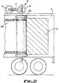
- a tool 10 is shown in position on a vehicle trailer 12.
- the tool 10 comprises a locating assembly consisting of a support frame 14 and wheels 18, 19. Wheels 18 are mounted on a cylindrical spar 16, located substantially horizontally across the width of the trailer 12. Wheel 19 is mounted on an auxiliary member 17, rigidly fixed to the spar 16 approximately perpendicularly. The wheels 18, 19 rest on the upper surface of the trailer, thereby suspending the support frame above the trailer and across the width of the trailer.
- Each spindle 20 is connected to a roll 22 of sheet material 24.
- the panel has a sheet of PES (polyethersulfone) fabric coated on both sides with PVC, with a matt lacquer applied to the printing side.
- the lacquer allows the panel to be printed.
- the sheet is UV stabilised, anti-wicking and fire-retardant.
- the sheet is substantially non-permeable in that it does not allow liquid or air to readily pass through it.
- the size of the sheet may vary to fit the size of the side of a trailer.
- the typical weight is approximately 460g/m 2 .
- the reverse of the sheet 24 has strips of a fastener 27a attached, for example by bonding with glue, ultrasonic bonding, stapling or stitching.
- the strips are attached around substantially the entire perimeter of the sheet, in that there are substantially no gaps left for air or fluid ingress after mounting on the truck or truck trailer.
- one or more fasteners may be placed away from the perimeter in order to provide support for the centre of the sheet.
- the truck trailer 12 has corresponding fasteners 27b arranged on its side surface, attached for example by bonding with glue, ultrasonic bonding, stapling or stitching.
- the roll 22 is formed around a central core (not shown).
- the spindle is connected to the central core via a locking disc 26, which also functions to cover the end of roll 22.
- the roll is releasably attachable from the locking disc, and thus is releasably from the tool itself.
- the spindle is rotatable with respect to the support frame, such that the entire roll may rotate about a vertical axis.
- the rotation mechanism of the spindle includes a clutch mechanism that is resistant to rotation of the roll, such that rotation will only be effected when a predetermined torque is applied to the roll. This allows a degree of tension to be maintained in the sheet material during the application process.
- the tool In use the tool is located in position on the vehicle as described above.
- the wheels 18, 19 rest on the upper surface of the vehicle, and suspend the support frame and rolls 22.
- the Figures show the panel being applied from the rear of the trailer towards the front, although the application could equally be used in the reverse direction, from front to rear.
- the outward edge of sheet material is withdrawn from the roll, just enough to align the fasteners at the trailing edge of the panel with the corresponding connectors on the surface of the vehicle.
- the fasteners are then pushed into engagement.
- the tool is then moved with respect to the trailer in a forward direction.
- the clutch mechanism initially resists the unrolling of the sheet material until sufficient tension has built up in the sheet.
- the tension is such that a predetermined torque acts to the roll, the sheet material is allowed to unroll and the tool moves along the length of the trailer.
- the fasteners 27a, 27b are pushed together to attach the panel.
- the tool allows the panel to be attached simply and quickly to the surface of a trailer.
- the gradual, linear attachment of the panel reduces the likelihood of forming air bubbles, creases, and wrinkles, all of which would distort the displayed image.
- the embodiment shown in Figure 1 and 2 includes a wheel 19 mounted on an auxiliary member 17.
- This arrangement allows the whole tool to be pivoted about the spar when loading or unloading rolls 22. By pivoting the tool (in a clockwise direction for the example shown in the Figures), extra ground clearance and manoeuvrability is gained.
- the wheel arrangement 17, 19 prevents pivoting of the tool in the opposite direction.
- Figures 3 and 4 show alternative embodiments of the invention.
- the support frame 14 comprises a pair of horizontal spars 16a, 16b, each having a pair of wheels 18a, 18b mounted thereon.
- the vertical spindles are mounted centrally on a linking frame member 42. This arrangement makes the tool less prone to pivoting about the spars 16, and thus provides additional stability to the tool.
- the embodiment of Figure 3 is provided with further support by way of the wheeled base assembly 32, which rests on the ground surface during use and storage of the tool.
- the assembly includes a height adjustable pillar 34, so that the weight of the tool can be distributed between the upper surface of the trailer and the wheeled base assembly.
- FIG. 5 An alternative embodiment is shown in Figure 5.
- This example includes a support frame arrangement that differs from the above-described embodiments, and has only a single applicator.
- the support frame includes a locating assembly 52 consisting of an upper frame element 52 running parallel to the vehicle surface.
- Mounted to the support frame are wheels 53, which rest on the upper surface during use.
- the tool is also provided with a vertical support element 51 running adjacent to the roll of sheet material 22.
- a lower frame element 55 At the lower end of the vertical support element is a lower frame element 55, having mounted thereto an additional wheel 56.
- the lower frame element is attached to the vertical support element 51 via a lockable pivot 54.
- the tool is located by placing the wheels on the upper surface of the trailer while the lower frame element 55 is aligned approximately parallel to the vertical support element 56. Subsequently, the wheel is locked into place on the underside of the vehicle trailer by rotating the lower frame element about the pivot. The tool is thus “clamped” onto the trailer.
- bracket 58 is pivotally mounted to the vertical support element 51.
- the roll 22 is locked to an upper spindle as before, by means of a locking disc (not shown). Thereafter, the bracket 58 is lifted such that it abuts the lower end of the roll.
- a locking disc may also be utilised at the lower end of the roll.
- twin-roll arrangement of Figures 1 to 4 could utilise a vertical support element and lower bracket as described with reference to Figure 5.
- rollers may be provided on the tool for urging the fastening materials together.
- Such rollers may extend rearward (with respect to the direction of movement of the tool) in alignment with the fastening material 27a, 27b.
- the tool could be used to remove a panel from a vehicle and coil the panel into a roll.
Landscapes
- Physics & Mathematics (AREA)
- General Physics & Mathematics (AREA)
- Engineering & Computer Science (AREA)
- Theoretical Computer Science (AREA)
- Business, Economics & Management (AREA)
- Accounting & Taxation (AREA)
- Marketing (AREA)
- Automobile Manufacture Line, Endless Track Vehicle, Trailer (AREA)
- Vehicle Waterproofing, Decoration, And Sanitation Devices (AREA)
- Lining Or Joining Of Plastics Or The Like (AREA)
Applications Claiming Priority (2)
| Application Number | Priority Date | Filing Date | Title |
|---|---|---|---|
| GB0221741A GB0221741D0 (en) | 2002-09-19 | 2002-09-19 | Application tool |
| GB0221741 | 2002-09-19 |
Publications (2)
| Publication Number | Publication Date |
|---|---|
| EP1400946A2 true EP1400946A2 (fr) | 2004-03-24 |
| EP1400946A3 EP1400946A3 (fr) | 2004-08-04 |
Family
ID=9944371
Family Applications (1)
| Application Number | Title | Priority Date | Filing Date |
|---|---|---|---|
| EP20030255405 Withdrawn EP1400946A3 (fr) | 2002-09-19 | 2003-08-29 | Outil d'application |
Country Status (3)
| Country | Link |
|---|---|
| US (1) | US20040144881A1 (fr) |
| EP (1) | EP1400946A3 (fr) |
| GB (2) | GB0221741D0 (fr) |
Families Citing this family (3)
| Publication number | Priority date | Publication date | Assignee | Title |
|---|---|---|---|---|
| US8534592B2 (en) * | 2010-07-01 | 2013-09-17 | Fred V. Payne | Apparatus and method for applying a tarp to trucking cargo |
| WO2018000086A1 (fr) * | 2016-06-27 | 2018-01-04 | Gordon Food Service Canada Ltd. | Dispositifs de recouvrement, d'affichage et/ou de remplacement de publicités sur un moyen de transport |
| PL238925B1 (pl) | 2019-01-22 | 2021-10-18 | Krzysztof Kurczuk | Wózek do przemieszczania, w pozycji pionowej, zrolowanych tapet i oklein ściennych w procesie przyklejania ich do ścian |
Citations (2)
| Publication number | Priority date | Publication date | Assignee | Title |
|---|---|---|---|---|
| WO2001091089A1 (fr) * | 2000-05-23 | 2001-11-29 | Polytrust Partners B.V. | Dispositif d'affichage d'informations |
| EP1288890A1 (fr) * | 2001-09-04 | 2003-03-05 | Kalman Böjthe | Dispositif d'information |
Family Cites Families (10)
| Publication number | Priority date | Publication date | Assignee | Title |
|---|---|---|---|---|
| US2598992A (en) * | 1949-09-02 | 1952-06-03 | Marion H Gordon | Paper dispenser |
| US4369614A (en) * | 1980-11-17 | 1983-01-25 | Tetzner Siegfried K | Wrapping apparatus |
| US4725328A (en) * | 1986-03-06 | 1988-02-16 | Warren Arnold | Single ply roofing applicator |
| US5042221A (en) * | 1989-03-28 | 1991-08-27 | Tac-Fast Systems Sa | Apparatus for applying wall covering and wall covering |
| WO1991015009A1 (fr) * | 1990-03-20 | 1991-10-03 | Scs Promotion Company Limited | Dispositif de fixation d'une affiche publicitaire |
| US5725173A (en) * | 1994-05-31 | 1998-03-10 | Marketing Displays, Inc. | Movable apparatus for installing flexible sign panels |
| US5667165A (en) * | 1994-08-01 | 1997-09-16 | Gardner; Gregory P. | Apparatus and method for application of flexible sheet stock |
| US5865943A (en) * | 1997-06-25 | 1999-02-02 | Minnesota Mining And Manufacturing Company | Apparatus for applying adhesive product to road barriers |
| GB0023386D0 (en) * | 2000-09-23 | 2000-11-08 | Watkinson Stephen | Wall covering applicator |
| US6705059B2 (en) * | 2001-09-27 | 2004-03-16 | Guardian Fiberglass, Inc. | Rolled fabric carriage apparatus |
-
2002
- 2002-09-19 GB GB0221741A patent/GB0221741D0/en not_active Ceased
-
2003
- 2003-08-29 GB GB0320249A patent/GB2394446B/en not_active Expired - Fee Related
- 2003-08-29 EP EP20030255405 patent/EP1400946A3/fr not_active Withdrawn
- 2003-09-16 US US10/663,429 patent/US20040144881A1/en not_active Abandoned
Patent Citations (2)
| Publication number | Priority date | Publication date | Assignee | Title |
|---|---|---|---|---|
| WO2001091089A1 (fr) * | 2000-05-23 | 2001-11-29 | Polytrust Partners B.V. | Dispositif d'affichage d'informations |
| EP1288890A1 (fr) * | 2001-09-04 | 2003-03-05 | Kalman Böjthe | Dispositif d'information |
Also Published As
| Publication number | Publication date |
|---|---|
| GB2394446B (en) | 2004-12-15 |
| US20040144881A1 (en) | 2004-07-29 |
| GB0320249D0 (en) | 2003-10-01 |
| GB2394446A (en) | 2004-04-28 |
| GB0221741D0 (en) | 2002-10-30 |
| EP1400946A3 (fr) | 2004-08-04 |
Similar Documents
| Publication | Publication Date | Title |
|---|---|---|
| AU2018224365B2 (en) | Universal target stand for ADAS static calibration, method of using the same, target plate for the same and use of a mat for the same | |
| US5845423A (en) | Advetising substrate attachable to trucks | |
| US5507109A (en) | Mobile advertising display | |
| US9540050B2 (en) | Stowable truck bed cover and height extender | |
| US7168197B2 (en) | System and method for mounting a sign | |
| AU2002310635B2 (en) | Method and apparatus for displaying advertisements on a vehicle | |
| US20150143729A1 (en) | Overhead banner stand fixture | |
| AU2002310635A1 (en) | Method and apparatus for displaying advertisements on a vehicle | |
| US8695251B2 (en) | Bulletin with peripheral strengthening, billboard assembly utilizing same and method of forming bulletin and mounting to billboard structure | |
| EP1400946A2 (fr) | Outil d'application | |
| US8096338B2 (en) | Method and apparatus for applying sheet material to a vehicle | |
| US20030164436A1 (en) | Display support | |
| US20080086923A1 (en) | Beadless Signage System and Method | |
| WO2002009081A1 (fr) | Systeme et procede permettant de creer un affichage de messages | |
| EP1408477A2 (fr) | Système publicitaire pour véhicule | |
| GB2474081A (en) | Billboard poster raising and mounting apparatus | |
| CN219489175U (zh) | 胶带夹具 | |
| US20120079790A1 (en) | Method and apparatus for applying sheet material to a building | |
| GB2233140A (en) | Poster frame | |
| JPH0624868Y2 (ja) | バン型車両 | |
| JPH0578035B2 (fr) | ||
| JPH07501892A (ja) | 改良されたディスプレイ構成とデバイス |
Legal Events
| Date | Code | Title | Description |
|---|---|---|---|
| PUAI | Public reference made under article 153(3) epc to a published international application that has entered the european phase |
Free format text: ORIGINAL CODE: 0009012 |
|
| AK | Designated contracting states |
Kind code of ref document: A2 Designated state(s): AT BE BG CH CY CZ DE DK EE ES FI FR GB GR HU IE IT LI LU MC NL PT RO SE SI SK TR |
|
| AX | Request for extension of the european patent |
Extension state: AL LT LV MK |
|
| PUAL | Search report despatched |
Free format text: ORIGINAL CODE: 0009013 |
|
| AK | Designated contracting states |
Kind code of ref document: A3 Designated state(s): AT BE BG CH CY CZ DE DK EE ES FI FR GB GR HU IE IT LI LU MC NL PT RO SE SI SK TR |
|
| AX | Request for extension of the european patent |
Extension state: AL LT LV MK |
|
| 17P | Request for examination filed |
Effective date: 20050204 |
|
| AKX | Designation fees paid |
Designated state(s): AT BE BG CH CY CZ DE DK EE ES FI FR GB GR HU IE IT LI LU MC NL PT RO SE SI SK TR |
|
| STAA | Information on the status of an ep patent application or granted ep patent |
Free format text: STATUS: THE APPLICATION IS DEEMED TO BE WITHDRAWN |
|
| 18D | Application deemed to be withdrawn |
Effective date: 20060301 |