EP1400700A1 - Fan device - Google Patents
Fan device Download PDFInfo
- Publication number
- EP1400700A1 EP1400700A1 EP02726494A EP02726494A EP1400700A1 EP 1400700 A1 EP1400700 A1 EP 1400700A1 EP 02726494 A EP02726494 A EP 02726494A EP 02726494 A EP02726494 A EP 02726494A EP 1400700 A1 EP1400700 A1 EP 1400700A1
- Authority
- EP
- European Patent Office
- Prior art keywords
- tube
- inner tube
- air
- vanes
- fan apparatus
- Prior art date
- Legal status (The legal status is an assumption and is not a legal conclusion. Google has not performed a legal analysis and makes no representation as to the accuracy of the status listed.)
- Withdrawn
Links
Images



Classifications
-
- F—MECHANICAL ENGINEERING; LIGHTING; HEATING; WEAPONS; BLASTING
- F04—POSITIVE - DISPLACEMENT MACHINES FOR LIQUIDS; PUMPS FOR LIQUIDS OR ELASTIC FLUIDS
- F04D—NON-POSITIVE-DISPLACEMENT PUMPS
- F04D29/00—Details, component parts, or accessories
- F04D29/26—Rotors specially for elastic fluids
- F04D29/28—Rotors specially for elastic fluids for centrifugal or helico-centrifugal pumps for radial-flow or helico-centrifugal pumps
- F04D29/281—Rotors specially for elastic fluids for centrifugal or helico-centrifugal pumps for radial-flow or helico-centrifugal pumps for fans or blowers
-
- F—MECHANICAL ENGINEERING; LIGHTING; HEATING; WEAPONS; BLASTING
- F04—POSITIVE - DISPLACEMENT MACHINES FOR LIQUIDS; PUMPS FOR LIQUIDS OR ELASTIC FLUIDS
- F04D—NON-POSITIVE-DISPLACEMENT PUMPS
- F04D29/00—Details, component parts, or accessories
- F04D29/58—Cooling; Heating; Diminishing heat transfer
- F04D29/582—Cooling; Heating; Diminishing heat transfer specially adapted for elastic fluid pumps
-
- F—MECHANICAL ENGINEERING; LIGHTING; HEATING; WEAPONS; BLASTING
- F04—POSITIVE - DISPLACEMENT MACHINES FOR LIQUIDS; PUMPS FOR LIQUIDS OR ELASTIC FLUIDS
- F04D—NON-POSITIVE-DISPLACEMENT PUMPS
- F04D29/00—Details, component parts, or accessories
- F04D29/58—Cooling; Heating; Diminishing heat transfer
- F04D29/582—Cooling; Heating; Diminishing heat transfer specially adapted for elastic fluid pumps
- F04D29/584—Cooling; Heating; Diminishing heat transfer specially adapted for elastic fluid pumps cooling or heating the machine
Definitions
- the present invention relates to a fan apparatus used for cooling a high-temperature chamber, such as in a tunnel kiln, a single kiln or the like.
- a kiln used in the ceramics industry for obtaining calcined products comprises an inlet line communicatably opened to the outside.
- the inlet line is provided with a fan.apparatus to draw outside air of room temperature into a kiln furnace to cool the calcined products baked using a burner or the like.
- the temperature inside the kiln furnace reaches 900°C to 1250°C.
- the cooling air drawn into the kiln furnace is room temperature, resulting in a drawback as described below. Specifically, since the temperature of the cooling air is extremely low compared to that inside the kiln furnace, a slight change in the flow rate of the inlet air leads to an abrupt change in the temperature inside the kiln furnace, thus it is difficult to maintain the temperature inside the kiln furnace within a predetermined range. In some cases, this results in calcined products that are cooled below the predetermined temperature and causes cracks to appear in the calcined products. In order to resolve the above drawback, it is preferable that the temperature of the cooling air be kept relatively high, i.e., 500°C to 750°C. However, there has been no known fan apparatus which has satisfactory heat resistance against such high-temperature air.
- An object of the present invention is to provide a fan apparatus having excellent heat resistance.
- a fan apparatus comprises a rotatably supported main body having a dual tube composed of an outer tube and an inner tube, and vanes protruding from the outer surface of the outer tube in an outward radial direction.
- the fan apparatus is provided with inlet holes to draw cooling air into the main body and outlet holes to discharge the drawn cooling air to the outside.
- the outer tube is provided with outer openings in the outer surface formed in a manner so as to communicate with the inside of the vanes.
- the inner tube is provided with inner openings in the outer surface in positions such that each inner opening corresponds to each outer opening.
- the fan apparatus is structured such that after the cooling air that is sent into the inner tube through the inlet holes is supplied inside the vanes through the inner openings and the outer openings, the cooling air passes through a space between the outer tube and the inner tube, and is discharged to the outside through the outlet holes.
- the fan apparatus further comprise a guiding member to guide the air supplied inside the vanes to flow along the inner surface of the vanes.
- the fan apparatus further comprise at least one radiating member disposed on the surface of the main body somewhere between at least one end of the main body and one of the vanes, a cover to cover the heat radiating member or members, and a cooling unit to supply a cooling medium inside the cover.
- air-cooling fins be provided on at least one of the inner surfaces of the outer tube, the inner tube and the vane.
- a first induction board spirally extending in the axial direction be arranged in the inner tube and a second induction board spirally extending in the axial direction be arranged in the space between the outer tube and the inner tube, and, by rotating the first and the second induction boards in a manner united with the main body, the air inside the inner tube be guided to the center of the inner tube along the axial direction and the air in the space between the outer tube and the inner tube be guided to the end portions of the outer tube along the axial direction.
- FIG. 1 is a perspective view showing the fan apparatus of the present invention.
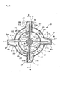
- Fig. 2 is a cross-sectional view of Fig. 1 taken in the direction of the arrows along the line A-A.
- Fig. 3 is a cross-sectional view of Fig. 2 taken in the direction of the arrows along the line B-B. In these figures, the airflow is shown by the arrows with thin lines.
- the fan apparatus of the present embodiment is disposed in an inlet line which makes the air inside a kiln furnace communicate with the outside air.
- the fan apparatus serves to draw air into the kiln furnace for quenching the calcined products.
- the temperature inside the kiln furnace during the calcining process reaches as high as 900°C to 1250°C, and when air of room temperature, for example, which is considerably colder than the air inside the kiln furnace, is drawn into the kiln furnace, the abrupt change in the temperature may cause cracks to appear in the calcined products.
- the fan apparatus is made of a material having high heat resistance, such as stainless steel or the like.
- the fan apparatus comprises a main body 3 having supporting members 7 attached to its ends, a driving axis 8 united with the main body 3 while penetrating through the main body 3 and having its ends projected, and four vanes 9 mounted on the outer surface of the main body 3.
- a portion of the main body 3 that includes the vanes 9 is disposed in a casing 10 (shown by dotted lines in the figure) and outside air drawn into the casing 10 is sent out of the casing 10 by the fan apparatus 1.
- the fan apparatus 1 is structured so that the length of the main body 3 is about 2.5 m and the height of the vanes 9 is about 0.4 m.
- the above described supporting members 7 are rotatably fitted to ball bearings 5 provided in an inlet line (not shown) and the fan apparatus 1 is rotated by a motor (not shown) mounted on the driving axis 8.
- the main body 3 is composed of a dual tube comprising an outer tube 11 and an inner tube 13 both having a tubular shape, with the ends of the inner tube 13 protruding from the outer tube 11.
- the vanes 9, which have substantially U-shaped cross-sections, are attached at 90-degree intervals to the outer surface of the outer tube 11.
- the driving axis 8 is slotted in the center of the inner tube 13, and four plate-shaped separators (guiding members) 17 are attached to the driving axis 8 radially in positions such that each separator corresponds to one of the vanes 9.
- inner slits (inner openings) 19 extending in the axial direction are provided on the outer surface of the inner tube 13 every 90 degrees.
- outer slits (outer openings) 21 extending in the axial direction are formed in positions corresponding to the inner slits 19.
- the separators 17 extend to inside the vanes 9 through the inner slits 19 and the outer slits 21. To one side of the separators 17, the periphery portions 19b of the inner slits 19 are attached. Thus, the inside of the inner tube 13 is partitioned into four inner tube passages 25. In each vane 9, a vane passage 27 communicating with the inner tube passage 25 and the outer tube passage 23 is formed to make the cooling air described later to flow therein. The cooling air is guided by the separator 17 extending in the vane passage 27 so as to flow along the inner surface of the vane 9. As described above, in the present embodiment, the inner tube passage 25, the vane passage 27 and the outer tube passage 23 are communicated to each other so that the cooling air passes trough them.
- each of the supporting members 7 fixed to both ends of the inner tube 13 four inlet holes 29 are formed in the position corresponding to one of the inner tube passages 25 and an air compressor (not shown) is connected to the supporting member 7 having a rotary joint 31 in between.
- the cooling air pumped by the air compressor is introduced into each inner tube passage 25 through the inlet holes 29.
- covering members 33 are mounted to cover both ends of the annular space.
- four outlet holes 35 are formed such that the position of each one corresponds to one of the outer tube passages 23 to discharge the air inside the outer tube 11 outside.
- the casing 10 is structured so as to have an inside diameter slightly greater than the largest outer diameter of the fan apparatus 1 and a tubular shape slightly shorter than the outer tube 11, and, in both ends of the casing 10, holes 37 are formed by projections of the ends of the outer tube 11.
- a pair of inlet ports 38 are formed to draw in outside air.
- a ventilation port 39 is formed to send the air inside the casing 10 out.
- an annular partition 40 having a slightly greater inside diameter than the outer diameter of the outer tube 11 is formed. The air drawn through the inlet port 38 is introduced toward the vane 9 through the space between the outer tube 11 and the partition 40, and then sent out of the casing 10 through the ventilation port 39 using the rotation of the vanes 9.
- the fan apparatus 1 having the above-described structure will be explained below.
- the calcined products are quenched by sending the air drawn into the casing 10 into the kiln furnace by rotary driving the main body 3 with a motor.
- the airflow drawn into the kiln furnace can be controlled by regulating the motor speed.
- the air compressor described above is turned on at the same time, air is sent into the inner tube passages 25 from both sides of the main body 3 through the supporting members 7. As shown in Fig. 2, the air flows in an outward radial direction from the inner tube passage 25 through the inner slits 19 and is guided into the vane passages 27 by the separators 17. The air drawn into the vane passages 27 flows along the inner surfaces of the vanes 9 while being guided by the separators 17. Thereby, the vanes 9 are directly cooled from inside. As shown in Fig. 3, the air passed through the vane passages 27 cools the outer tube 11 while passing thorough the outer tube passages 23, and then is discharged from the fan apparatus 1 through the outlet holes 35.
- the fan apparatus 1 allows the main body 3 and the vanes 9 of the fan apparatus 1, which are used under a high temperature, to be directly cooled, since the cooling air is pumped into the main body 3 from the air compressor and drawn into the vane passages 27 and the outer tube passages 23 through the inner tube passages 25.
- the heat resistance of the fan apparatus 1 can be greatly improved. This improved heat resistance prevents a decrease in the strength of the fan apparatus when used under a high temperature and enables the fan apparatus 1 to be rotated at high speed. This makes it possible to send a sufficient volume of air into the kiln furnace.
- the effect for cooling the vanes 9 can be greatly improved owing to the above-mentioned distinctive structure.
- a plurality of inner slits 19 extending in the axial direction are formed such that the position of each one corresponds to one of the vanes 9.
- the cooling air drawn in the axial direction from both ends of the inner tube 13 can be sent outward in a radial direction through the inner slits 19.
- the air sent through the inner slits 19 is led into the vane passages 27 by the separators 17 and guided so as to flow along the inner surfaces of the vanes 9. Therefore, the entire surface of the vanes 9 can be sufficiently cooled from inside by the air.
- air of room temperature can be used as the cooling air.
- the cooling air is circulated in the main body 3 and inside the vanes 9 by feeding the cooling air under pressure using the air compressor; however, for example, by arranging the inner tube 13 and the outer tube 11 as described below, a large volume of cooling air can be circulated.
- first screw boards (first induction boards) 34 fixed to the driving axis 8 are arranged on both sides of the separator 17 in a manner such that they extend from one end of the inner tube 13 to one end of the separator 17.
- the two first screw boards 34 have helix directions opposite to each other, and their outer edges are fixed to the inner surface of the inner tube 13. Therefore, if the main body 3 rotates in a predetermined direction, the first screw boards 34 also rotate as a unit with it. Accordingly, it generates airflow directed from both ends of the inner tube 13 to the separator 17. Thereby, the air fed into the inner tube 13 from the air compressor is guided in the direction of the separator 17, and a large volume of cooling air is reliably sent in the vane passage 27.
- second screw boards (second induction boards) 36 are formed in a manner such that they have helix directions opposite to each other.
- the second screw boards 36 are fixed to the outer surface of the inner tube 13 and their outer edge is attached to the inner surface of the outer tube 11.
- Each of the .second screw boards 36 has a helix direction opposite to that of the first screw board 34 provided in the inner tube 13 located inside the outer tube 11. Therefore, if the second screw boards 36 rotate in a predetermined direction together with the main body 3, airflow is generated in a direction opposite to that in the inner tube 13, i.e., from the separator 17 to both ends of the outer tube 11.
- the air passed through the vane passages 27 and the outer tube passages 23 is guided to both ends of the outer tube 11 and a large volume of cooling air is reliably released from outlet holes 35.
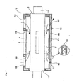
- Fig. 5 is a cross-sectional view of a fan apparatus of the second embodiment. In this figure, the airflow is shown by the arrows with thin lines as described above, and the flow of the cooling water described below is shown by the arrows with bold lines.
- the second embodiment is different from the above-described first embodiment in that it is equipped with a cooling device.
- the second embodiment has the same structure as in the first embodiment, and therefore those elements that are identical to the elements of the first embodiment are identified with the same numerical symbols, and repetitious explanation will be omitted.
- the fan apparatus 51 is provided with cooling devices 53 on both ends of the main body 3 to release the heat conducted in the direction from the main body 3 toward the supporting members 7.
- These cooling devices 53 each comprise a heat radiating member 55 disposed between the inner tube 13 and the supporting member 7, a cover 57 covering the heat radiating member 55, and a pump 59 and a tank 60 circulating the cooling water (cooling medium) to be supplied inside the cover 57.
- the pump 59 and the tank 60 in the present embodiment serve as the cooling unit of the present invention.
- the heat radiating members 55 each comprise a connecting member 61 connecting the end portion of the inner tube 13 with the supporting member 7, and air-cooling fins 63 composed of doughnut-shaped disks fixed to the connecting member 61.
- the heat radiating effect can be improved by increasing the surface area of the heat radiating member 55 by providing the air-cooling fins 63.
- communicating holes 58 connecting the inlet holes 29 in the supporting member 7 with the inner tube 13 are formed such that the position of each one corresponds to one of the inlet holes 29.
- the cover 57 is formed in a tubular shape and structured so as to cover the bearing 5 and the heat radiating member 55, with one end portion thereof being attached to the outer surface of the bearing 5.
- a supply hole 57a is formed to receive the cooling water sent from the pump.
- a discharge hole 57b is formed to discharge the cooling water to the outside. The cooling water drained through the discharge hole 57b is first sent back to the tank 60 and is then fed into the cover 57 again by the pump 59.
- the fan apparatus 51 having the above-described structure will be described below.
- the driving axis 8, the supporting members 7, the heat radiating members 55 and the main body 3 are rotated in a united manner and the sending of ventilation air into the kiln furnace is initiated.
- the air pumped from the air compressor is drawn into the inner tube passages 25 of the inner tube 13 through the supporting members 7 and the connecting members 61, and thereby the main body 3 and the vanes 9 are cooled.
- the cooling device 53 the cooling water pumped from the pump 59 is fed into the cover 57 and cools the connecting members 61 and the air-cooling fins 63.
- the air-cooling fins 63 rotate with the main body 3 in a united manner, and the cooling water is thereby evenly discharged to the air-cooling fins 63, enhancing the heat radiating effect.
- both ends of the main body 3 are cooled by the cooling devices 53 and this prevents heat from being conducted from the main body 3 to the bearing 5 and the rotary joint 31a.
- deformation of the bearings 5 and the rotary joints 31, and a malfunction of the motor can be prevented. If the bearings 5 were to be deformed, the rotational accuracy of the fan apparatus 51 would be lowered. This could make it impossible to supply an appropriate amount of air or cause a malfunction. Therefore, providing the cooling device 53 of the present embodiment is especially advantageous.
- each of the heat radiating members 55 is disposed between the supporting member 7 and the inner tube 13; however, for example, the heat radiating member 55 can be united with the supporting member 7 in a manner such that a portion of the supporting member 7 functions as a heat radiating member to directly cool the supporting member 7. It is also possible to obtain the same effect described above by disposing the heat radiating members 55 on the surface of the main body 3 somewhere between the vanes 9 and the ends of the main body 3, for example, on some portion of the inner tube 13 protruding from the outer tube 11.
- the air-cooling fins 63 in the heat radiating member 55 are not essential and can be provided, if necessary, depending on the heat radiating capability required.
- the cooling water is circulated between the pump 59 and the heat radiating member 55; however, it can be structured such that the cooling water is not circulated but simply ejected toward the heat radiating member 55.
- the structure of the present embodiment is preferable in which the cooling water is collected by the pump.
- air can be used instead of water as a cooling medium.
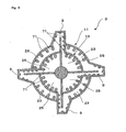
- air-cooling fins 71 can be arranged on the inner surfaces of the outer tube 11, the inner tube 13 and the vanes 9 to cool the fan apparatus with enhanced efficiency.
- Such an arrangement can increase the surface area of the outer tube passages 23, the inner tube passages 25 and the vane passages 27 and enhance the heat radiating effect thereof, resulting in further improved heat resistance of the fan apparatus.
- the casing 10 is formed as a dual tube comprising an outer tube 81 and an inner tube 83, and, in the outer surface of the outer tube 81, an inlet hole 85 and a discharge hole 87 are formed, wherein the inlet hole 85 draws in the cooling air from outside and the discharge hole 87 discharges the used cooling air to the outside.
- This arrangement allows the cooling air to circulate between the outer tube 81 and the inner tube 83, and the casing 10 is thereby made cool.
- each of the inner tube passages 25, outer tube passages 23 and vanes 9 are provided.
- the number of inner tube passages 25, outer tube passages 23 and vanes 9 is not limited to four and can be selected depending on the operating conditions of the fan apparatus.
- the shapes of the outer tube 11 and the inner tube 13 are not limited to tubular shapes, and they can have polygonal cross-sections.
- the length of the main body 3 and the height of the vanes 9 are not limited within the range described above, and can be selected depending on the performance required in the fan apparatus. It is also possible to make the outer tube 11 and the inner tube 13 have the same length.
- both ends of the fan apparatus 1 are rotatably supported; however, it is also possible to build it in a manner such that only one of the ends is supported or the cooling air is drawn in from one end thereof. In this case, the cooling device is mounted on only that end.
- the inner and outer openings are formed out of the slits extending in the axial direction.
- the screw boards 34 and 36 disposed in the main body 3 are not limited to the ones described above and their lengths and shapes, etc., can be selected depending on the specifications of the fan apparatus.
- the structure of the casing 10 is not limited to the above embodiments, and the shape and dimensions of the casing, the positions and dimensions of the inlet ports, the ventilation ports and the partitions are selected depending on the size and required specifications of the fan apparatus.
- the fan apparatus of the present invention is applied to a single kiln for use in the ceramics industry; however, its usage is not limited to this.
- the fan apparatus can be applied to a tunnel kiln in which a cart carrying products to be calcined is made to pass through a preheating zone, a calcining zone, a quenching zone and a cooling zone to obtain the calcined products.
- the fan apparatus can be disposed in the inlet line, which introduces the cooling air into the quenching zone.
- the fan apparatus can be applied not only to the above kilns but also to any high-temperature chambers including heat treatment furnaces, heating furnaces or like industrial furnaces, which are used under high temperatures or which carry gases of high temperature.
- the cooling air drawn into the inner tube passes through the inside of the vanes and the outer tube, and then is discharged from the main body. Therefore, the air directly cools the vanes and the main body of the fan apparatus, which is used under high temperatures.
- the heat resistance of the fan apparatus can be greatly improved. Furthermore, the improved heat resistance can prevent a decrease in the strength of the fan apparatus under high temperatures. Therefore, the fan apparatus can be rotated at high speed and generate sufficient airflow.
- the cooling effect of the vanes can be greatly improved by having the structure as described below.
- the inner openings are formed in the outer surface of the inner tube in positions such that each inner opening corresponds to one of the vanes, and the air introduced into the inner tube along the axial direction can thereby be discharged outward in a radial direction through the inner openings.
- the air drawn into the inner tube can be reliably sent in the direction of the vanes.
- the air sent from the inner tube is guided by guiding members so as to flow along the inner surfaces of the vanes, and therefore the entire surface of the vanes can be adequately cooled from the inside.
- the fan apparatus is structured in a manner such that a heat radiating member is provided on the surface of the main body somewhere between at least one of the ends of the main body and the vanes, and such that a cooling medium is supplied to the heat radiating member, it is possible to prevent the heat of the main body from being conducted outward in a radial direction.
Landscapes
- Engineering & Computer Science (AREA)
- Mechanical Engineering (AREA)
- General Engineering & Computer Science (AREA)
- Physics & Mathematics (AREA)
- Thermal Sciences (AREA)
- Structures Of Non-Positive Displacement Pumps (AREA)
- Tunnel Furnaces (AREA)
- Furnace Details (AREA)
Abstract
A fan apparatus 1, which comprises a main body 3
having a dual tube composed of an outer tube 11 and an
inner tube 13 and being rotatably supported by supporting
members 7, and vanes 9 protruding from the outer surface
of the outer tube 11 in the outward radial direction, the
fan apparatus 1 being provided with inlet holes 29 to draw
cooling air into the main body 3 and outlet holes 35 to
discharge the cooling air to the outside, wherein the
outer tube 11 has outer slits 21 formed in the outer
surface thereof so as to communicate with the inside of
the vanes 9, the inner tube 13 has inner slits 19 in
positions such that each inner slit corresponds to each
outer slit 21 in the outer surface thereof, and the
cooling air that is sent into the inner tube 13 is
supplied inside the vanes 9 through the inner slits 19 and
the outer slits 21, and after passing through the space
between the outer tube 11 and the inner tube 13, the air
is discharged from the outlet holes 35.
Description
The present invention relates to a fan apparatus
used for cooling a high-temperature chamber, such as in a
tunnel kiln, a single kiln or the like.
A kiln used in the ceramics industry for
obtaining calcined products, including roof tiles, pottery
and the like, comprises an inlet line communicatably
opened to the outside. The inlet line is provided with a
fan.apparatus to draw outside air of room temperature into
a kiln furnace to cool the calcined products baked using a
burner or the like.
In a kiln having such a structure, the
temperature inside the kiln furnace reaches 900°C to
1250°C. On the other hand, the cooling air drawn into the
kiln furnace is room temperature, resulting in a drawback
as described below. Specifically, since the temperature
of the cooling air is extremely low compared to that
inside the kiln furnace, a slight change in the flow rate
of the inlet air leads to an abrupt change in the
temperature inside the kiln furnace, thus it is difficult
to maintain the temperature inside the kiln furnace within
a predetermined range. In some cases, this results in
calcined products that are cooled below the predetermined
temperature and causes cracks to appear in the calcined
products. In order to resolve the above drawback, it is
preferable that the temperature of the cooling air be kept
relatively high, i.e., 500°C to 750°C. However, there has
been no known fan apparatus which has satisfactory heat
resistance against such high-temperature air.
An object of the present invention is to provide
a fan apparatus having excellent heat resistance.
To achieve the above object, according to the
present invention, a fan apparatus comprises a rotatably
supported main body having a dual tube composed of an
outer tube and an inner tube, and vanes protruding from
the outer surface of the outer tube in an outward radial
direction. The fan apparatus is provided with inlet holes
to draw cooling air into the main body and outlet holes to
discharge the drawn cooling air to the outside. The outer
tube is provided with outer openings in the outer surface
formed in a manner so as to communicate with the inside of
the vanes. The inner tube is provided with inner openings
in the outer surface in positions such that each inner
opening corresponds to each outer opening. The fan
apparatus is structured such that after the cooling air
that is sent into the inner tube through the inlet holes
is supplied inside the vanes through the inner openings
and the outer openings, the cooling air passes through a
space between the outer tube and the inner tube, and is
discharged to the outside through the outlet holes.
It is preferable that the fan apparatus further
comprise a guiding member to guide the air supplied inside
the vanes to flow along the inner surface of the vanes.
It is more preferable that the fan apparatus
further comprise at least one radiating member disposed on
the surface of the main body somewhere between at least
one end of the main body and one of the vanes, a cover to
cover the heat radiating member or members, and a cooling
unit to supply a cooling medium inside the cover.
It is also preferable that air-cooling fins be
provided on at least one of the inner surfaces of the
outer tube, the inner tube and the vane.
It is particularly preferable that a first
induction board spirally extending in the axial direction
be arranged in the inner tube and a second induction board
spirally extending in the axial direction be arranged in
the space between the outer tube and the inner tube, and,
by rotating the first and the second induction boards in a
manner united with the main body, the air inside the inner
tube be guided to the center of the inner tube along the
axial direction and the air in the space between the outer
tube and the inner tube be guided to the end portions of
the outer tube along the axial direction.
A first embodiment in which a fan apparatus of
the invention is applied to a single kiln for use in the
ceramics industry will be described below in more detail
with reference to Figs. 1 to 3. Fig. 1 is a perspective
view showing the fan apparatus of the present invention.
Fig. 2 is a cross-sectional view of Fig. 1 taken in the
direction of the arrows along the line A-A. Fig. 3 is a
cross-sectional view of Fig. 2 taken in the direction of
the arrows along the line B-B. In these figures, the
airflow is shown by the arrows with thin lines.
In a single kiln, the fan apparatus of the
present embodiment is disposed in an inlet line which
makes the air inside a kiln furnace communicate with the
outside air. The fan apparatus serves to draw air into
the kiln furnace for quenching the calcined products. In
this embodiment, it is preferable that the air drawn into
the kiln furnace to quench the calcined products have a
temperature within the range of 500°C to 750°C. This is
because, in the single kiln, the temperature inside the
kiln furnace during the calcining process reaches as high
as 900°C to 1250°C, and when air of room temperature, for
example, which is considerably colder than the air inside
the kiln furnace, is drawn into the kiln furnace, the
abrupt change in the temperature may cause cracks to
appear in the calcined products.
The fan apparatus is made of a material having
high heat resistance, such as stainless steel or the like.
As shown in Fig. 1, the fan apparatus comprises a main
body 3 having supporting members 7 attached to its ends, a
driving axis 8 united with the main body 3 while
penetrating through the main body 3 and having its ends
projected, and four vanes 9 mounted on the outer surface
of the main body 3. As described below, a portion of the
main body 3 that includes the vanes 9 is disposed in a
casing 10 (shown by dotted lines in the figure) and
outside air drawn into the casing 10 is sent out of the
casing 10 by the fan apparatus 1.
The fan apparatus 1 is structured so that the
length of the main body 3 is about 2.5 m and the height of
the vanes 9 is about 0.4 m. The above described supporting
members 7 are rotatably fitted to ball bearings 5 provided
in an inlet line (not shown) and the fan apparatus 1 is
rotated by a motor (not shown) mounted on the driving axis
8.
As shown in Fig. 2, the main body 3 is composed
of a dual tube comprising an outer tube 11 and an inner
tube 13 both having a tubular shape, with the ends of the
inner tube 13 protruding from the outer tube 11. The
vanes 9, which have substantially U-shaped cross-sections,
are attached at 90-degree intervals to the outer surface
of the outer tube 11. The driving axis 8 is slotted in
the center of the inner tube 13, and four plate-shaped
separators (guiding members) 17 are attached to the
driving axis 8 radially in positions such that each
separator corresponds to one of the vanes 9.
Four inner slits (inner openings) 19 extending
in the axial direction are provided on the outer surface
of the inner tube 13 every 90 degrees. Similarly, on the
outer surface of the outer tube 11, four outer slits
(outer openings) 21 extending in the axial direction are
formed in positions corresponding to the inner slits 19.
By attaching edge portions 19a and 21a of the inner slits
19 and the corresponding outer slits 21 to 9a of the vanes
9, the annular space formed between the outer tube 11 and
the inner tube 13 is partitioned into four outer tube
passages 23. The end portions 9b of the other side of the
vanes 9 are attached to edge portions 21b of the outer
slits 21, and therefore the outer slits 21 are completely
covered by the vanes 9.
The separators 17 extend to inside the vanes 9
through the inner slits 19 and the outer slits 21. To one
side of the separators 17, the periphery portions 19b of
the inner slits 19 are attached. Thus, the inside of the
inner tube 13 is partitioned into four inner tube passages
25. In each vane 9, a vane passage 27 communicating with
the inner tube passage 25 and the outer tube passage 23 is
formed to make the cooling air described later to flow
therein. The cooling air is guided by the separator 17
extending in the vane passage 27 so as to flow along the
inner surface of the vane 9. As described above, in the
present embodiment, the inner tube passage 25, the vane
passage 27 and the outer tube passage 23 are communicated
to each other so that the cooling air passes trough them.
As shown in Fig. 3, in each of the supporting
members 7 fixed to both ends of the inner tube 13, four
inlet holes 29 are formed in the position corresponding to
one of the inner tube passages 25 and an air compressor
(not shown) is connected to the supporting member 7 having
a rotary joint 31 in between. The cooling air pumped by
the air compressor is introduced into each inner tube
passage 25 through the inlet holes 29.
As shown in the figure, to both ends of the
outer tube 11, covering members 33 are mounted to cover
both ends of the annular space. In these covering members
33, four outlet holes 35 are formed such that the position
of each one corresponds to one of the outer tube passages
23 to discharge the air inside the outer tube 11 outside.
As shown in Figs. 1 and 3, the casing 10 is
structured so as to have an inside diameter slightly
greater than the largest outer diameter of the fan
apparatus 1 and a tubular shape slightly shorter than the
outer tube 11, and, in both ends of the casing 10, holes
37 are formed by projections of the ends of the outer tube
11. In the outer surface of the casing 10, between the
end portion of the vane 9 and the end portion of the outer
tube 11, a pair of inlet ports 38 are formed to draw in
outside air. Between the pair of inlet ports 38, a
ventilation port 39 is formed to send the air inside the
casing 10 out. In addition, on the inside surface of the
casing 10, between the inlet port 38 and the ventilation
port 39, an annular partition 40 having a slightly greater
inside diameter than the outer diameter of the outer tube
11 is formed. The air drawn through the inlet port 38 is
introduced toward the vane 9 through the space between the
outer tube 11 and the partition 40, and then sent out of
the casing 10 through the ventilation port 39 using the
rotation of the vanes 9.
The operation of the fan apparatus 1 having the
above-described structure will be explained below. Upon
completion of the calcining process for obtaining calcined
products, as shown in Fig. 1, the calcined products are
quenched by sending the air drawn into the casing 10 into
the kiln furnace by rotary driving the main body 3 with a
motor. During this process, the airflow drawn into the
kiln furnace can be controlled by regulating the motor
speed.
If the air compressor described above is turned
on at the same time, air is sent into the inner tube
passages 25 from both sides of the main body 3 through the
supporting members 7. As shown in Fig. 2, the air flows
in an outward radial direction from the inner tube passage
25 through the inner slits 19 and is guided into the vane
passages 27 by the separators 17. The air drawn into the
vane passages 27 flows along the inner surfaces of the
vanes 9 while being guided by the separators 17. Thereby,
the vanes 9 are directly cooled from inside. As shown in
Fig. 3, the air passed through the vane passages 27 cools
the outer tube 11 while passing thorough the outer tube
passages 23, and then is discharged from the fan apparatus
1 through the outlet holes 35.
As described above, the fan apparatus 1
according to the present embodiment allows the main body 3
and the vanes 9 of the fan apparatus 1, which are used
under a high temperature, to be directly cooled, since the
cooling air is pumped into the main body 3 from the air
compressor and drawn into the vane passages 27 and the
outer tube passages 23 through the inner tube passages 25.
As a result, the heat resistance of the fan apparatus 1
can be greatly improved. This improved heat resistance
prevents a decrease in the strength of the fan apparatus
when used under a high temperature and enables the fan
apparatus 1 to be rotated at high speed. This makes it
possible to send a sufficient volume of air into the kiln
furnace.
Specifically, according to the fan apparatus 1
of the present embodiment, the effect for cooling the
vanes 9 can be greatly improved owing to the above-mentioned
distinctive structure. In other words, in the
inner tube 13, a plurality of inner slits 19 extending in
the axial direction are formed such that the position of
each one corresponds to one of the vanes 9. Thereby, the
cooling air drawn in the axial direction from both ends of
the inner tube 13 can be sent outward in a radial
direction through the inner slits 19. As a result, it is
possible to reliably send the air in the direction of each
vane 9. Furthermore, the air sent through the inner slits
19 is led into the vane passages 27 by the separators 17
and guided so as to flow along the inner surfaces of the
vanes 9. Therefore, the entire surface of the vanes 9 can
be sufficiently cooled from inside by the air. Here, for
example, air of room temperature can be used as the
cooling air.
According to the present embodiment, the cooling
air is circulated in the main body 3 and inside the vanes
9 by feeding the cooling air under pressure using the air
compressor; however, for example, by arranging the inner
tube 13 and the outer tube 11 as described below, a large
volume of cooling air can be circulated.
As shown in Fig. 4, inside the inner tube 13, a
pair of first screw boards (first induction boards) 34
fixed to the driving axis 8 are arranged on both sides of
the separator 17 in a manner such that they extend from
one end of the inner tube 13 to one end of the separator
17. The two first screw boards 34 have helix directions
opposite to each other, and their outer edges are fixed to
the inner surface of the inner tube 13. Therefore, if the
main body 3 rotates in a predetermined direction, the
first screw boards 34 also rotate as a unit with it.
Accordingly, it generates airflow directed from both ends
of the inner tube 13 to the separator 17. Thereby, the
air fed into the inner tube 13 from the air compressor is
guided in the direction of the separator 17, and a large
volume of cooling air is reliably sent in the vane passage
27.
In the annular space formed between the inner
tube 13 and the outer tube 11, similar to inside the inner
tube 13, a pair of second screw boards (second induction
boards) 36 are formed in a manner such that they have
helix directions opposite to each other. The second screw
boards 36 are fixed to the outer surface of the inner tube
13 and their outer edge is attached to the inner surface
of the outer tube 11. Each of the .second screw boards 36
has a helix direction opposite to that of the first screw
board 34 provided in the inner tube 13 located inside the
outer tube 11. Therefore, if the second screw boards 36
rotate in a predetermined direction together with the main
body 3, airflow is generated in a direction opposite to
that in the inner tube 13, i.e., from the separator 17 to
both ends of the outer tube 11. The air passed through
the vane passages 27 and the outer tube passages 23 is
guided to both ends of the outer tube 11 and a large
volume of cooling air is reliably released from outlet
holes 35.
Thus, by providing the first and the second
screw boards 34 and 36 in the inner tube 13 and the space
between the outer tube 11 and the inner tube 13,
respectively, it is possible to draw a large volume of
cooling air into the main body 3 and inside the vanes 9.
As a result, the cooling ability of the fan apparatus 1
can be greatly improved.
In the first embodiment, only the main body 3
and the vanes 9 are cooled by the cooling air; however,
heat in the main body 3 may be conducted to the bearing 5,
the rotary joint 31 and the motor through the supporting
.members 7 and the driving axis 8. In order to prevent
this, heat resistance of the entire fan apparatus should
be further improved by providing a cooling device as
described below. A second embodiment according to the
present invention will be explained below with reference
to Fig. 5. Fig. 5 is a cross-sectional view of a fan
apparatus of the second embodiment. In this figure, the
airflow is shown by the arrows with thin lines as
described above, and the flow of the cooling water
described below is shown by the arrows with bold lines.
The second embodiment is different from the
above-described first embodiment in that it is equipped
with a cooling device. In other respects, the second
embodiment has the same structure as in the first
embodiment, and therefore those elements that are
identical to the elements of the first embodiment are
identified with the same numerical symbols, and
repetitious explanation will be omitted.
As shown in Fig. 5, the fan apparatus 51
according to the second embodiment is provided with
cooling devices 53 on both ends of the main body 3 to
release the heat conducted in the direction from the main
body 3 toward the supporting members 7. These cooling
devices 53 each comprise a heat radiating member 55
disposed between the inner tube 13 and the supporting
member 7, a cover 57 covering the heat radiating member 55,
and a pump 59 and a tank 60 circulating the cooling water
(cooling medium) to be supplied inside the cover 57. Here,
the pump 59 and the tank 60 in the present embodiment
serve as the cooling unit of the present invention.
The heat radiating members 55 each comprise a
connecting member 61 connecting the end portion of the
inner tube 13 with the supporting member 7, and air-cooling
fins 63 composed of doughnut-shaped disks fixed to
the connecting member 61. The heat radiating effect can
be improved by increasing the surface area of the heat
radiating member 55 by providing the air-cooling fins 63.
In the connecting member 61, communicating holes 58
connecting the inlet holes 29 in the supporting member 7
with the inner tube 13 are formed such that the position
of each one corresponds to one of the inlet holes 29.
The cover 57 is formed in a tubular shape and
structured so as to cover the bearing 5 and the heat
radiating member 55, with one end portion thereof being
attached to the outer surface of the bearing 5. In the
upper portion of the cover 57, a supply hole 57a is formed
to receive the cooling water sent from the pump. In the
lower portion thereof, a discharge hole 57b is formed to
discharge the cooling water to the outside. The cooling
water drained through the discharge hole 57b is first sent
back to the tank 60 and is then fed into the cover 57
again by the pump 59.
The operation of the fan apparatus 51 having the
above-described structure will be described below. When
the motor and the air compressor are turned on, the
driving axis 8, the supporting members 7, the heat
radiating members 55 and the main body 3 are rotated in a
united manner and the sending of ventilation air into the
kiln furnace is initiated. The air pumped from the air
compressor is drawn into the inner tube passages 25 of the
inner tube 13 through the supporting members 7 and the
connecting members 61, and thereby the main body 3 and the
vanes 9 are cooled. On the other hand, in the cooling
device 53, the cooling water pumped from the pump 59 is
fed into the cover 57 and cools the connecting members 61
and the air-cooling fins 63. Here, the air-cooling fins
63 rotate with the main body 3 in a united manner, and the
cooling water is thereby evenly discharged to the air-cooling
fins 63, enhancing the heat radiating effect.
As described above, an effect similar to that of
the first embodiment can be obtained by the present
embodiment. In addition, both ends of the main body 3 are
cooled by the cooling devices 53 and this prevents heat
from being conducted from the main body 3 to the bearing 5
and the rotary joint 31a. As a result, deformation of the
bearings 5 and the rotary joints 31, and a malfunction of
the motor can be prevented. If the bearings 5 were to be
deformed, the rotational accuracy of the fan apparatus 51
would be lowered. This could make it impossible to supply
an appropriate amount of air or cause a malfunction.
Therefore, providing the cooling device 53 of the present
embodiment is especially advantageous.
In the present embodiment, each of the heat
radiating members 55 is disposed between the supporting
member 7 and the inner tube 13; however, for example, the
heat radiating member 55 can be united with the supporting
member 7 in a manner such that a portion of the supporting
member 7 functions as a heat radiating member to directly
cool the supporting member 7. It is also possible to
obtain the same effect described above by disposing the
heat radiating members 55 on the surface of the main body
3 somewhere between the vanes 9 and the ends of the main
body 3, for example, on some portion of the inner tube 13
protruding from the outer tube 11. The air-cooling fins
63 in the heat radiating member 55 are not essential and
can be provided, if necessary, depending on the heat
radiating capability required. Furthermore, according to
the present embodiment, the cooling water is circulated
between the pump 59 and the heat radiating member 55;
however, it can be structured such that the cooling water
is not circulated but simply ejected toward the heat
radiating member 55. However, from a viewpoint of the
effective use of water, the structure of the present
embodiment is preferable in which the cooling water is
collected by the pump. Alternately, air can be used
instead of water as a cooling medium.
It is to be understood that the scope of the
present invention is not limited to the embodiments
described above and various changes and modifications may
be made to the invention without departing from the spirit
and scope thereof. For example, as shown in Fig. 6, air-cooling
fins 71 can be arranged on the inner surfaces of
the outer tube 11, the inner tube 13 and the vanes 9 to
cool the fan apparatus with enhanced efficiency. Such an
arrangement can increase the surface area of the outer
tube passages 23, the inner tube passages 25 and the vane
passages 27 and enhance the heat radiating effect thereof,
resulting in further improved heat resistance of the fan
apparatus. Note also that, it is not absolutely necessary
to provide the air-cooling fins 71 in all of the passages
23, 25 and 27 described above, and they can be disposed on
the inner surfaces of only one or two of the passages.
It is also possible to have a structure in which
not only the fan apparatus 1 but also the casing 10 is
cooled. For example, as shown in Fig. 7, the casing 10 is
formed as a dual tube comprising an outer tube 81 and an
inner tube 83, and, in the outer surface of the outer tube
81, an inlet hole 85 and a discharge hole 87 are formed,
wherein the inlet hole 85 draws in the cooling air from
outside and the discharge hole 87 discharges the used
cooling air to the outside. This arrangement allows the
cooling air to circulate between the outer tube 81 and the
inner tube 83, and the casing 10 is thereby made cool. As
shown in the enlarged view of the figure, it is also
possible to provide air-cooling fins 89 on the inner
surface of the outer tube 81 and the outer surface of the
inner tube 83. This arrangement enhances the heat
radiating effect, and the casing 10 is thereby made cool
in a more efficient manner.
In the above embodiments, four each of the inner
tube passages 25, outer tube passages 23 and vanes 9 are
provided. However, the number of inner tube passages 25,
outer tube passages 23 and vanes 9 is not limited to four
and can be selected depending on the operating conditions
of the fan apparatus. Furthermore, the shapes of the
outer tube 11 and the inner tube 13 are not limited to
tubular shapes, and they can have polygonal cross-sections.
In addition, the length of the main body 3 and the height
of the vanes 9 are not limited within the range described
above, and can be selected depending on the performance
required in the fan apparatus. It is also possible to
make the outer tube 11 and the inner tube 13 have the same
length.
In the above embodiments, both ends of the fan
apparatus 1 are rotatably supported; however, it is also
possible to build it in a manner such that only one of the
ends is supported or the cooling air is drawn in from one
end thereof. In this case, the cooling device is mounted
on only that end.
In the above embodiments, the inner and outer
openings are formed out of the slits extending in the
axial direction. However, it is also possible, for
example, to arrange a plurality of holes in a line along
the axial direction. Furthermore, the screw boards 34 and
36 disposed in the main body 3 are not limited to the ones
described above and their lengths and shapes, etc., can be
selected depending on the specifications of the fan
apparatus.
In addition, the structure of the casing 10 is
not limited to the above embodiments, and the shape and
dimensions of the casing, the positions and dimensions of
the inlet ports, the ventilation ports and the partitions
are selected depending on the size and required
specifications of the fan apparatus.
In the above embodiments, the fan apparatus of
the present invention is applied to a single kiln for use
in the ceramics industry; however, its usage is not
limited to this. For example, the fan apparatus can be
applied to a tunnel kiln in which a cart carrying products
to be calcined is made to pass through a preheating zone,
a calcining zone, a quenching zone and a cooling zone to
obtain the calcined products. In this case, the fan
apparatus can be disposed in the inlet line, which
introduces the cooling air into the quenching zone. The
fan apparatus can be applied not only to the above kilns
but also to any high-temperature chambers including heat
treatment furnaces, heating furnaces or like industrial
furnaces, which are used under high temperatures or which
carry gases of high temperature.
As described above, in the fan apparatus
according to the present invention, the cooling air drawn
into the inner tube passes through the inside of the vanes
and the outer tube, and then is discharged from the main
body. Therefore, the air directly cools the vanes and the
main body of the fan apparatus, which is used under high
temperatures. As a result, the heat resistance of the fan
apparatus can be greatly improved. Furthermore, the
improved heat resistance can prevent a decrease in the
strength of the fan apparatus under high temperatures.
Therefore, the fan apparatus can be rotated at high speed
and generate sufficient airflow.
In the present invention, the cooling effect of
the vanes can be greatly improved by having the structure
as described below. Specifically, the inner openings are
formed in the outer surface of the inner tube in positions
such that each inner opening corresponds to one of the
vanes, and the air introduced into the inner tube along
the axial direction can thereby be discharged outward in a
radial direction through the inner openings. As a result,
the air drawn into the inner tube can be reliably sent in
the direction of the vanes. Furthermore, the air sent
from the inner tube is guided by guiding members so as to
flow along the inner surfaces of the vanes, and therefore
the entire surface of the vanes can be adequately cooled
from the inside.
If the fan apparatus is structured in a manner
such that a heat radiating member is provided on the
surface of the main body somewhere between at least one of
the ends of the main body and the vanes, and such that a
cooling medium is supplied to the heat radiating member,
it is possible to prevent the heat of the main body from
being conducted outward in a radial direction.
Claims (5)
- A fan apparatus comprising:a rotatably supported main body having a dual tube composed of an outer tube and an inner tube; andvanes protruding from the outer surface of the outer tube in an outward radial direction,the main body being provided with inlet holes to draw cooling air into the main body and outlet holes to discharge the drawn cooling air to the outside,the outer tube being provided with outer openings in the outer surface thereof formed in a manner so as to communicate with the inside of the vanes,the inner tube being provided with inner openings in the outer surface thereof in positions such that each inner opening corresponds to each outer opening,the fan apparatus being structured such that after the cooling air that is sent into the inner tube through the inlet holes is supplied inside the vanes through the inner openings and the outer openings, the cooling air passes through a space between the outer tube and the inner tube and is discharged to the outside through the outlet holes.
- The fan apparatus according to claim 1, which further comprises a guiding member to guide the air supplied inside the vanes to flow along the inner surface of the vanes.
- The fan apparatus according to claim 1, which further comprises at least one heat radiating member disposed on the surface of the main body somewhere between at least one end of the main body and one of the vanes, a cover to cover the heat radiating member or members, and a cooling unit to supply a cooling medium inside the cover.
- The fan apparatus according to claim 1, wherein air-cooling fins are provided on at least one of the inner surfaces of the outer tube, the inner tube and the vane.
- The fan apparatus according to claim 1, which further comprises a first induction board spirally extending in the axial direction in the inner tube and a second induction board spirally extending in the axial direction in the space between the outer tube and the inner tube,
being structured such that, by rotating the first and the second induction boards in a manner united with the main body, the air inside the inner tube is guided to the center of the inner tube along the axial direction and the air in the space between the outer tube and the inner tube is guided to the end portions of the outer tube along the axial direction.
Applications Claiming Priority (3)
| Application Number | Priority Date | Filing Date | Title |
|---|---|---|---|
| JP2001166660 | 2001-06-01 | ||
| JP2001166660A JP2002364596A (en) | 2001-06-01 | 2001-06-01 | Fan device |
| PCT/JP2002/005105 WO2002099289A1 (en) | 2001-06-01 | 2002-05-27 | Fan device |
Publications (2)
| Publication Number | Publication Date |
|---|---|
| EP1400700A1 true EP1400700A1 (en) | 2004-03-24 |
| EP1400700A4 EP1400700A4 (en) | 2005-01-05 |
Family
ID=19009168
Family Applications (1)
| Application Number | Title | Priority Date | Filing Date |
|---|---|---|---|
| EP02726494A Withdrawn EP1400700A4 (en) | 2001-06-01 | 2002-05-27 | Fan device |
Country Status (5)
| Country | Link |
|---|---|
| EP (1) | EP1400700A4 (en) |
| JP (1) | JP2002364596A (en) |
| CN (1) | CN1253663C (en) |
| TW (1) | TW546445B (en) |
| WO (1) | WO2002099289A1 (en) |
Families Citing this family (1)
| Publication number | Priority date | Publication date | Assignee | Title |
|---|---|---|---|---|
| CN114738326B (en) * | 2022-04-28 | 2023-10-03 | 安徽理工大学 | A kind of diversion pressurized energy-saving centrifugal fan |
Family Cites Families (6)
| Publication number | Priority date | Publication date | Assignee | Title |
|---|---|---|---|---|
| GB470694A (en) * | 1937-03-10 | 1937-08-19 | Xavier De Spirlet | Improvements in roasting furnaces |
| US2656973A (en) * | 1949-06-09 | 1953-10-27 | Reliance Electric & Eng Co | Electric motor for driving a device within a compartment |
| DE2836163A1 (en) * | 1978-08-18 | 1980-03-06 | Kloeckner Humboldt Deutz Ag | DEVICE FOR CONVEYING AND / OR TREATING HOT GASES |
| JPS60164699U (en) * | 1984-04-09 | 1985-11-01 | 日産自動車株式会社 | centrifugal blower |
| JPS6326100U (en) * | 1986-08-01 | 1988-02-20 | ||
| JPH0286998A (en) * | 1988-09-22 | 1990-03-27 | Mitsubishi Electric Corp | Blower |
-
2001
- 2001-06-01 JP JP2001166660A patent/JP2002364596A/en active Pending
-
2002
- 2002-05-27 CN CN 02811148 patent/CN1253663C/en not_active Expired - Fee Related
- 2002-05-27 EP EP02726494A patent/EP1400700A4/en not_active Withdrawn
- 2002-05-27 WO PCT/JP2002/005105 patent/WO2002099289A1/en not_active Ceased
- 2002-08-07 TW TW91117790A patent/TW546445B/en not_active IP Right Cessation
Also Published As
| Publication number | Publication date |
|---|---|
| EP1400700A4 (en) | 2005-01-05 |
| JP2002364596A (en) | 2002-12-18 |
| CN1253663C (en) | 2006-04-26 |
| TW546445B (en) | 2003-08-11 |
| CN1513090A (en) | 2004-07-14 |
| WO2002099289A1 (en) | 2002-12-12 |
Similar Documents
| Publication | Publication Date | Title |
|---|---|---|
| US3347059A (en) | Heat pump | |
| KR101888156B1 (en) | turbo compressor with separated paths for cooling air | |
| JP2019515194A (en) | Turbo compressor with intercooler | |
| CN1549912A (en) | Method and device for exchanging energy and/or mass | |
| CN104236282B (en) | Collar plate shape apparatus for kneading apparatus | |
| US10228198B2 (en) | Multi-disk heat exchanger and fan unit | |
| US3081019A (en) | Fan | |
| US4073338A (en) | Heat exchangers | |
| CN100422561C (en) | Cooled Screw Vacuum Pump | |
| US5445218A (en) | Compact heat exchanger | |
| US4252181A (en) | Heat recovering fan | |
| CA1144421A (en) | Device for pumping and exchanging heat between separate fluids | |
| CN101206052A (en) | Hanging air conditioner and its control method | |
| KR20010065013A (en) | Convection device for microwave oven | |
| US4672622A (en) | Gas transport laser apparatus with axial gas flow | |
| JP6657387B2 (en) | Method for cooling a compressor or vacuum pump and compressor or vacuum pump applied to such method | |
| SE527867C2 (en) | Cooling installation | |
| JP2002364596A (en) | Fan device | |
| CN112479545A (en) | Sludge drying device and using method thereof | |
| CN212538833U (en) | Air cooling device of kiln head screw conveyer | |
| US2215945A (en) | Hot air fan for driers | |
| KR100536862B1 (en) | Waste heat recovery equipment of a raise the recovery heat duty by a distribute operation of symmetrical gear's of rotor | |
| JP4444472B2 (en) | Reflow soldering method and apparatus | |
| CN116067191B (en) | Flue gas cooler of calciner | |
| JPH0680027A (en) | Engine cooling device |
Legal Events
| Date | Code | Title | Description |
|---|---|---|---|
| PUAI | Public reference made under article 153(3) epc to a published international application that has entered the european phase |
Free format text: ORIGINAL CODE: 0009012 |
|
| 17P | Request for examination filed |
Effective date: 20031209 |
|
| AK | Designated contracting states |
Kind code of ref document: A1 Designated state(s): AT BE CH CY DE DK ES FI FR GB GR IE IT LI LU MC NL PT SE TR |
|
| AX | Request for extension of the european patent |
Extension state: AL LT LV MK RO SI |
|
| A4 | Supplementary search report drawn up and despatched |
Effective date: 20041123 |
|
| STAA | Information on the status of an ep patent application or granted ep patent |
Free format text: STATUS: THE APPLICATION HAS BEEN WITHDRAWN |
|
| 17Q | First examination report despatched |
Effective date: 20050209 |
|
| 18W | Application withdrawn |
Effective date: 20050131 |