EP1400677A2 - Einspritzsystem - Google Patents
Einspritzsystem Download PDFInfo
- Publication number
- EP1400677A2 EP1400677A2 EP03255969A EP03255969A EP1400677A2 EP 1400677 A2 EP1400677 A2 EP 1400677A2 EP 03255969 A EP03255969 A EP 03255969A EP 03255969 A EP03255969 A EP 03255969A EP 1400677 A2 EP1400677 A2 EP 1400677A2
- Authority
- EP
- European Patent Office
- Prior art keywords
- injector
- injectors
- switch means
- charge
- discharge
- Prior art date
- Legal status (The legal status is an assumption and is not a legal conclusion. Google has not performed a legal analysis and makes no representation as to the accuracy of the status listed.)
- Granted
Links
- 238000002347 injection Methods 0.000 claims abstract description 54
- 239000007924 injection Substances 0.000 claims abstract description 54
- 238000007599 discharging Methods 0.000 claims abstract description 48
- 230000004913 activation Effects 0.000 claims abstract description 12
- 238000000034 method Methods 0.000 claims description 21
- 238000002485 combustion reaction Methods 0.000 claims description 5
- 230000003213 activating effect Effects 0.000 claims description 3
- 238000012544 monitoring process Methods 0.000 claims description 3
- 239000000446 fuel Substances 0.000 description 30
- 239000003990 capacitor Substances 0.000 description 19
- 238000004146 energy storage Methods 0.000 description 11
- 230000000694 effects Effects 0.000 description 8
- 230000008901 benefit Effects 0.000 description 5
- 238000006073 displacement reaction Methods 0.000 description 5
- 230000008859 change Effects 0.000 description 4
- 238000010586 diagram Methods 0.000 description 2
- 230000006870 function Effects 0.000 description 2
- 230000008569 process Effects 0.000 description 2
- 238000011084 recovery Methods 0.000 description 2
- 238000013459 approach Methods 0.000 description 1
- 230000009286 beneficial effect Effects 0.000 description 1
- 230000008602 contraction Effects 0.000 description 1
- 238000013016 damping Methods 0.000 description 1
- 239000002283 diesel fuel Substances 0.000 description 1
- 230000000977 initiatory effect Effects 0.000 description 1
- 238000007493 shaping process Methods 0.000 description 1
Images


Classifications
-
- F—MECHANICAL ENGINEERING; LIGHTING; HEATING; WEAPONS; BLASTING
- F02—COMBUSTION ENGINES; HOT-GAS OR COMBUSTION-PRODUCT ENGINE PLANTS
- F02D—CONTROLLING COMBUSTION ENGINES
- F02D41/00—Electrical control of supply of combustible mixture or its constituents
- F02D41/20—Output circuits, e.g. for controlling currents in command coils
- F02D41/2096—Output circuits, e.g. for controlling currents in command coils for controlling piezoelectric injectors
-
- F—MECHANICAL ENGINEERING; LIGHTING; HEATING; WEAPONS; BLASTING
- F02—COMBUSTION ENGINES; HOT-GAS OR COMBUSTION-PRODUCT ENGINE PLANTS
- F02D—CONTROLLING COMBUSTION ENGINES
- F02D41/00—Electrical control of supply of combustible mixture or its constituents
- F02D41/20—Output circuits, e.g. for controlling currents in command coils
- F02D2041/202—Output circuits, e.g. for controlling currents in command coils characterised by the control of the circuit
- F02D2041/2051—Output circuits, e.g. for controlling currents in command coils characterised by the control of the circuit using voltage control
-
- F—MECHANICAL ENGINEERING; LIGHTING; HEATING; WEAPONS; BLASTING
- F02—COMBUSTION ENGINES; HOT-GAS OR COMBUSTION-PRODUCT ENGINE PLANTS
- F02D—CONTROLLING COMBUSTION ENGINES
- F02D41/00—Electrical control of supply of combustible mixture or its constituents
- F02D41/20—Output circuits, e.g. for controlling currents in command coils
- F02D2041/202—Output circuits, e.g. for controlling currents in command coils characterised by the control of the circuit
- F02D2041/2058—Output circuits, e.g. for controlling currents in command coils characterised by the control of the circuit using information of the actual current value
-
- F—MECHANICAL ENGINEERING; LIGHTING; HEATING; WEAPONS; BLASTING
- F02—COMBUSTION ENGINES; HOT-GAS OR COMBUSTION-PRODUCT ENGINE PLANTS
- F02D—CONTROLLING COMBUSTION ENGINES
- F02D41/00—Electrical control of supply of combustible mixture or its constituents
- F02D41/20—Output circuits, e.g. for controlling currents in command coils
- F02D2041/2068—Output circuits, e.g. for controlling currents in command coils characterised by the circuit design or special circuit elements
- F02D2041/2072—Bridge circuits, i.e. the load being placed in the diagonal of a bridge to be controlled in both directions
-
- F—MECHANICAL ENGINEERING; LIGHTING; HEATING; WEAPONS; BLASTING
- F02—COMBUSTION ENGINES; HOT-GAS OR COMBUSTION-PRODUCT ENGINE PLANTS
- F02D—CONTROLLING COMBUSTION ENGINES
- F02D41/00—Electrical control of supply of combustible mixture or its constituents
- F02D41/20—Output circuits, e.g. for controlling currents in command coils
- F02D2041/2068—Output circuits, e.g. for controlling currents in command coils characterised by the circuit design or special circuit elements
- F02D2041/2082—Output circuits, e.g. for controlling currents in command coils characterised by the circuit design or special circuit elements the circuit being adapted to distribute current between different actuators or recuperate energy from actuators
Definitions
- the invention relates to an injector system for an internal combustion engine, the injector system including a plurality of injectors of the type having a piezoelectric actuator for controlling injector valve needle movement.
- the invention also relates to a method of controlling an injector system incorporating a plurality of piezoelectric injectors.
- Automotive vehicle engines are generally equipped with fuel injectors for injecting fuel (e.g. gasoline or diesel fuel) into the individual cylinders or intake manifold of the engine.
- fuel injectors are coupled to a fuel rail containing high pressure fuel that is delivered by way of a fuel delivery system.
- the injectors typically employ a valve needle that is actuated to open and close so as to control the amount of high pressure fuel metered from the fuel rail and injected into the corresponding engine cylinder or intake manifold.
- Piezoelectric fuel injectors employ piezoelectric actuators including a stack of piezoelectric elements.
- the metering of fuel is generally achieved by controlling the electrical voltage potential, or charge, applied to the piezoelectric elements so as to vary the degree to which the stack extends and contracts.
- the extent of expansion and contraction of the piezoelectric elements varies the extent and direction of travel of the valve needle, towards and away from a valve needle seating, so as to control the duration for which injection occurs at a given fuel pressure. Control of the piezoelectric actuator therefore controls the fuel delivery quantity.
- the piezoelectric actuator In order to inject fuel, so as to provide an "injection event", the piezoelectric actuator undergoes a discharge and a charge phase.
- the injector In one type of piezoelectric injector (positive-charge displacement injectors), the injector is configured such that charging of the actuator stack causes the needle to lift away from the valve needle seating to start the injection event, with discharging of the actuator stack causing the needle to seat to end the injection event.
- piezoelectric injector negative-charge displacement injectors
- piezoelectric fuel injectors require relatively high voltages (in the hundreds of volts) and high currents (tens of amps) in order to function properly.
- Known drive circuitry for controlling piezoelectric fuel injectors is generally complicated and usually requires extensive energy.
- an injector system for use in an internal combustion engine, the injector system including at least first and second injectors, and a drive circuit comprising select switch means for controlling independent selection of the first or second injector to permit a discharging current to be supplied to the selected injector during a discharging mode so as to initiate an injection event and charge/discharge switch means for controlling whether the discharging current is supplied to the selected injector or whether a charging current is supplied to the selected injector during a charging mode so as to terminate the injection event, wherein the first and second injectors are arranged electrically in parallel and operatively connected to the select switch means and the charge/discharge switch means so that activation of the charge/discharge switch means to terminate the injection event results in respective voltages across the first and second injectors tending to equalise.
- the injector system prefferably includes at least first and second injectors, each of which has a piezoelectric actuator.
- the invention is equally applicable, however, to systems in which the injectors have generally capacitive-like properties.
- the advantage of arranging the injectors in parallel is that, at the end of the charging mode upon termination of the injection event by a selected injector, any voltage across the selected injector in excess of a predetermined voltage charge threshold tends to equalise with the voltage across the unselected injector(s). Thus, positive voltage ringing is damped due to excess energy being shared between the injectors. Accuracy of control of the injector and injector efficiency is therefore improved.
- the injector system may, but need not, be manufactured to include voltage supply means for supplying charging and discharging voltages across the piezoelectric actuators.
- the drive circuit is configured as a half H-bridge circuit having a middle circuit branch, with the first and second injectors being arranged electrically in parallel with one another in the middle circuit branch.
- the charge/discharge switch means includes first and second charge/discharge switches, each of which permits unidirectional current flow when activated and prevents current flow when deactivated.
- the select switch means preferably includes a first select switch for enabling the discharge current to flow through the first injector during the discharging mode thereof and a second select switch for enabling the discharge current to flow through the second injector during the discharging mode thereof.
- the drive circuit of the system is preferably configured so that the discharging mode is achieved by activation (closing) of the second charge/discharge switch and activation (closing) of the select switch of the selected injector that is required to perform the injection event.
- the charging mode is conveniently achieved by activation of the first charge/discharge switch.
- the drive circuit may also include voltage sensing means for monitoring the voltage across the selected injector (and also the unselected injector, if desired) and control means for receiving a signal indicative of the sensed voltage and providing a terminate control signal to the charge/discharge switch means to terminate the charging mode of the selected injector once a threshold charge voltage (V CHARGE ) is sensed.
- the control means may also be arranged to provide an initiate signal to the charge/discharge switch means to initiate the charging mode of the selected injector.
- control means is arranged to control the select switch means so that the selected injector is de-selected following the end of the discharging mode, prior to a subsequent charging mode.
- control means is arranged to control the select switch means so that the selected injector is re-selected at the start of the subsequent charging mode.
- control means is arranged to control the select switch means so that the selected injector is held selected at the end of the discharge mode and is held selected throughout (and preferably also following) the subsequent charging mode.
- control means is arranged to control the select switch means so that both the first and second injectors are selected (that is, in a selected state) at the end of the charging mode and for a period thereafter, thereby to equalise the voltages across the injectors prior to a subsequent discharging mode, preferably equalising to a value just less than the threshold charge value.
- the drive circuit may be configured to operate by providing a further additional control signal at engine start-up to equalise the voltages across each of the injectors to just less than the threshold charge voltage, and/or to provide the further additional control signal at engine shut-down.
- the invention is applicable to a bank of at least two injectors, with each injector being arranged to inject fuel to an associated combustion space or engine cylinder.
- the bank may include any number of injectors, and an engine may have more than one injector bank depending on the number of engine cylinders.
- the injector system includes first and second injector banks, so that the drive circuit of the system controls operation of the first and second injector banks, the first injector bank including a first injector and a second injector and the second injector bank including a third injector and a fourth injector, the drive circuit including first select switch means associated with the first injector bank for controlling independent selection of the first or second injector to permit a discharging current to be supplied to the selected injector during a discharging mode so as to initiate an injection event, second select switch means associated with the second injector bank for controlling independent selection of the third or fourth injector to permit a discharging current to be supplied to the selected injector during a discharging mode so as to initiate an injection event, charge/discharge switch means for controlling whether the discharging current is supplied to the selected injector of either the first or the second injector bank or whether a charging current is supplied to said selected injector during a charging mode so as to terminate the injection event, and wherein the injectors of each bank
- the charge/discharge switch means includes first and second charge/discharge switches for each bank, one being activated to initiating charging and one being activated to initiate discharging of a selected injector of the associated bank.
- a drive circuit for controlling the first and second injectors of the injector system set out in the accompanying claim set, wherein the drive circuit further includes at least first and second parallel current paths, each of which is provided with connection means connectable across a respective one of the first and second injectors of the system, in use, so that said injectors are arranged electrically in parallel with one another.
- another aspect of the invention is to provide an electrical drive circuit, which is not manufactured to include the injectors of the system with which it is used but which includes only electrical circuit components including the connection means for connection with the injectors, in use.
- the drive circuit of this aspect of the invention may include any of the preferred or optional features of the drive circuit aspect of the injector system described previously and set out in the accompanying claims.
- a control method for an injector system for use in an internal combustion engine comprising controlling independent selection of the first or the second injector using select switch means to permit a discharging current to be supplied to the selected injector so as to initiate an injection event, controlling whether the charging current is supplied to the selected injector or whether a discharging current is supplied to the selected injector so as to terminate the injection event using charge/discharge switch means, arranging the first and second injectors electrically in parallel with one another and operatively connecting the injectors to the select switch means and the charge/discharge switch means, and activating the charge/discharge switch means so as to terminate the injection event and so that respective voltages across the first and second injectors at the end of the injection event tend to equalise.
- the method may include providing a first control signal to the select switch means to de-select the selected injector at the end of the discharging mode.
- the method may then include providing a further control signal to the select switch means to re-select the selected injector for the subsequent charging mode.
- the method may alternatively include maintaining the selected injector in a selected state at the end of the discharging mode.
- the method may include providing an additional control signal to the select switch means to ensure both the first and second injectors are selected at the end of the charging mode of either one, and for a period thereafter, thereby to equalise the voltages across the first and second injectors, prior to a subsequent injection event. This may be achieved by deselecting the first injector following the discharge mode and then reselecting the first injector at or just prior to the charging mode and, at substantially the same time, selecting the second injector at or just prior to the charging mode.
- the method includes providing a further additional control signal to the select switch means to ensure both the first and second injectors are selected upon engine start-up and/or upon engine shut-down.
- a piezoelectric actuator for a fuel injector of the negative-charge displacement type including a stack 10 of piezoelectric elements 12 (only two of which are numbered).
- the stack 10 is energisable and de-energisable to effect a change in length of the stack 10, and thereby to control movement of an injector valve needle towards and away from a valve needle seating so as to control injection.
- a contracted state length x1
- a positive, charging voltage is applied across the stack 10 to energise the stack.
- an extended state length x2
- a negative, discharging voltage is applied across the stack to de-energise the stack 10.
- FIG. 2 shows a drive pulse 14, or voltage waveform, which is applied to the stack 10 to change between the contracted (x1) and extended (x2) states.
- the voltage waveform 14 varies between a charging voltage (V CHARGE ) and a discharging voltage (V DISCHARGE ) ⁇
- V CHARGE charging voltage
- V DISCHARGE discharging voltage
- the injectors are arranged in 'banks' of two or more injectors, as illustrated by dashed lines and referenced at 21.
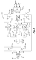
- Figure 3 therefore shows one injector bank 21 having three injectors 22a, 22b, 22c.
- This bank of injectors may be one of two identical injector banks (only one of which is shown in Figure 3) in a six cylinder engine, with each injector 22a, 22b, 22c of one bank delivering fuel to a different one of three engine cylinders and each injector of the other bank delivering fuel to a different one of three other engine cylinders.
- the arrangement and operation of the second injector bank is substantially identical to the first, and so only the first bank having injectors 22a, 22b, 22c will be described in detail. It will be appreciated by the skilled reader that further injector banks (each having two or more injectors) may be included in the system, depending on engine configuration and requirements.
- the injectors 22a, 22b, 22c are of the negative-charge displacement type, as described previously.
- each individual injector is selected for injection under the control of a drive control circuit, referred to generally as 24, including select switch means operatively connected to the injectors 22a, 2b, 22c to permit independent control of each switch S1, S2, S3 thereof and charge/discharge switch means, Q1, Q2, which is operatively connected to the injectors 22a, 22b, 22c of a given bank so as to control injection by any one of them, depending on which is selected.
- a control arrangement for controlling operation of the circuit 24 includes a microprocessor and memory of an Engine Control Module (ECM).
- ECM Engine Control Module
- the microprocessor and memory are configured to provide control signals for the select switches S1, S2, S3 and the charge/discharge switches Q1, Q2 so as to initiate a discharge operation (the discharge mode) in which the selected injector is opened.
- the microprocessor and the memory are also configured to provide control signals for the charge/discharge switch means Q1, Q2 so as to initiate a charging operation (the charging mode) in which the selected injector is closed, and may be configured to further provide control signals for the select switch means S1, S2, S3 during or following the charging mode, if necessary.
- the ways in which the microprocessor controls operation of the switch means S1, S2, S3, Q1, Q2 to control injection will be described in further detail below.
- the drive circuit 24 employs a half H-bridge configuration and forms part of the ECM.
- the drive circuit 24 receives control signals from the ECM microprocessor and memory.
- a middle circuit branch of the half H-bridge serves as a bi-directional current path 26 and is provided with connection means in the form of positive and negative electrical connector terminals, at points x and y respectively, in each of three parallel current paths.
- Each injector is connected between the connection means (x, y) in a respective one of the parallel current paths, so that the injectors are arranged electrically in parallel.
- the middle circuit branch also includes an inductor 28, coupled in series with the parallel connection of the injectors 22a, 22b, 22c.
- Each injector has the electrical characteristics similar to those of a capacitor, with its piezoelectric actuator stack being chargeable to hold a voltage which is the potential difference between the charge (+) and discharge (-) terminals of the injector 22a, 22b, 22c. Charging and discharging of each injector 22a, 22b, 22c is achieved by controlling the current flow through the bi-directional current path 26 by means of the microprocessor.
- the drive circuit 24 further includes a voltage input 30 for receiving a voltage V S from a voltage source, such as vehicle battery voltage.
- the voltage V S is increased to a higher step-up voltage, V C1 , via a step up transformer 32 (DC/DC converter).
- the step-up voltage, V C1 is typically of the order of 200-300V and is applied to a first energy storage capacitor C1 via a first diode D1.
- the step-up transformer also applies voltage V C2 to a second energy storage capacitor C2 via a second diode D2.
- the step-up transformer has a return line coupled to the second diode D2.
- V C2 is of the order of 100V.
- other suitable electrical components may be used to provide a similar function to the step up transformer 32, if preferred.
- the charge/discharge switch means of the drive circuit 24 includes first and second charge/discharge switches Q1 and Q2 respectively for controlling the charging and discharging operations of the injector.
- Each switch Q1, Q2 may take the form of an n-channel insulated gate bipolar transistor (IGBT) having a gate controlling current flow from the collector to the emitter.
- IGBT insulated gate bipolar transistor
- Each of the charge/discharge switches Q1, Q2 allows for unidirectional current flow from the collector to the emitter when turned on, and prevents current flow when turned off.
- Each switch Q1, Q2 has a respective recirculation diode D3, D4 connected across it to allow a recirculation current to return to the energy storage capacitors C1, C2 during an 'energy recovery' or 'recirculation' mode of operation of the circuit 24, as described in further detail below.
- Each of the injectors 22a, 22b, 22c is connected in series with an associated select switch, S1, S2, S3 respectively, of the select switch means.
- Each of the first, second and third select switches S1, S2, S3 typically takes the form of an IGBT having a gate coupled to a gate drive which is powered at a bias supply input.
- select switch S1 associated with the first injector 22a for example, is activated (or turned on) in conjunction with the charge/discharge switch Q2 being closed, current flow is permitted in a discharge direction through the selected injector.
- a diode D5 is connected in parallel with the select switch S1 to allow current flow in the charge direction during a charging mode of operation.
- diodes D6 and D7 are connected in parallel with respective ones of the selects switches S2 and S3 for the second and third injectors.
- a further diode D8 is provided between the bi-directional current path 26 on the injector side of the inductor 28 and the positive terminal of the first energy storage capacitor C1.
- Another diode D9 is provided between the negative terminal of the second energy storage capacitor C2 and the bi-directional current path 26 on the injector side of the inductor 28.
- the further diode D8 provides a 'voltage clamping effect' for a selected injector at the end of its charging mode, as it prevents the injector from being driven to voltages higher than V C1 .
- the other diode D9 provides a recirculation path for current flow during a discharge mode of operation, as will be described in further detail later.
- a current flow sensing and control means 38 may be connected within the bi-directional current path 26 to sense the current, compare the sensed current with predetermined first and second current thresholds, I 1 and I 2 respectively, and generate output signals accordingly.
- I 1 represents a peak current threshold
- I 2 represents a recirculation current threshold.
- Both of the current threshold values, I 1 and I 2 are stored in the microprocessor and memory, along with a charge voltage threshold (V CHARGE ) and a discharge voltage threshold (V DISCHARGE ). If required, and preferably so, the current thresholds, I 1 and I 2 , and the voltage thresholds, V CHARGE , V DISCHARGE , may be adjustable.
- a voltage sensing means (not shown) is also provided to sense the voltage, V SENSE , across the injector that is selected for injection.
- the control means of the circuit 24 includes control logic 34 for receiving the output of the current sensing and control means 38, the sensed voltage, V SENSE , from the positive terminal (+) of the injectors 22a, 22b, 22c, and the various output signals provided from the microprocessor and memory.
- the control logic 34 may include software executed by the microprocessor and memory for processing the various inputs so as to generate control signals for each of the charge/discharge switches, Q1, Q2 and each of the injector select switches S1, S2 and S3.
- the drive circuit 24 operates in a discharge phase or mode to open a selected one of the fuel injectors 22a, 22b, 22c, whereby the piezoelectric stack of the selected injector is contracted to cause the injector valve needle to lift from its seating.
- the drive circuit 24 also operates in a charge mode to close the fuel injectors 22a, 22b, 22c, whereby the piezoelectric stack of the selected injector is extended to cause the injector valve needle re-seat.
- the second switch Q2 is activated (closed). Additionally, one of the injector select switches S1, S2, S3 is activated to select a desired one of the injectors 22a, 22b, 22c for injection. For example, if it is required to inject with the first injector 22a, the select switch S1 is closed. The other two injector select switches S2, S3 of the bank remain de-activated at this time as the second and third injectors 22b, 22c with which they are associated are not required to inject.
- the current sensing and control means 38 monitors the current flow through the bi-directional path 26 as it builds up and, as soon as the peak current threshold I 1 is reached, an output signal is generated to initiate de-activation (opening) of the second switch Q2. At this point, the current that is built up in the inductor 28 recirculates through the diode D3 associated with the first (open) switch Q1. As a consequence, the direction of current flow through the inductor 28 and the selected one of the injectors 22a does not change. This is a "recirculation phase" of the discharging mode of operation of the drive circuit 24.
- the current sensing and control means 38 monitors the recirculation current, so that when the recirculation current has fallen below the recirculation current threshold I 2 , the comparator generates a signal to reactivate the second charge/discharge switch Q2 to continue the discharge operation.
- V DISCHARGE discharge voltage level
- the select switch S1 of the injector 22a is deactivated to open. Therefore, at the end of the discharge mode all three select switches S1, S2, S3 are deactivated (open).
- the first charge/discharge switch Q1 In order to charge (close) the injector 22a, the first charge/discharge switch Q1 is activated to close allowing a charge current, I CHARGE , to flow through the current path 26. This is referred to as charging mode of operation of the drive circuit. It is an essential step of the charging mode of operation that the first charge/discharge switch Q1 is activated to close.
- the select switch means S1, S2, S3 may be operated during and following the charging mode, as described in further detail below.
- the select switch S1 of the first injector 22a which has previously been injecting, is activated to close again and a bi-directional current flows through the injector 22a during and following the charging mode.
- the second and third switches S2, S3 remain open.
- the majority of the charge current I CHARGE during the charging mode will flow through the previously discharged injector (i.e. the selected injector 22a in the example described), as this injector is at a much lower voltage level (V DISCHARGE ) at the start of the charging phase than the unselected injectors 22b, 22c (which are maintained, substantially, at voltage level V CHARGE ).
- the remaining injectors 22b, 22c that were not previously discharged will receive current if the corresponding voltages across them have dropped below the charge voltage threshold V CHARGE ⁇
- V CHARGE charge voltage threshold
- the unselected injectors 22b, 22c may discharge to a level around 199V, from 200V.
- the current flow sensing and control means 38 monitors the current build-up and, as soon as the peak current threshold I 1 is reached, the control logic 34 generates a control signal to open the first switch Q1. At this point, the current that has built up in the inductor 28 recirculates through the diode D4 associated with the second (open) switch Q2. This is a recirculation phase of the charging mode of operation of the drive circuit 24. The direction of current flow through the inductor 28 and the injectors 22a, 22b, 22c does not change during the recirculation phase.
- this recirculation phase current flows from the negative side of the 100 volt power supply across the capacitor C2, through the diode D4, through the inductor 28 and the injectors 22a, 22b, 22c, through the diodes D5, D6, D7, and the current sensing and control means 38 and into the positive side of energy storage capacitor C2.
- energy from the inductor 28 and the piezoelectric injectors 22a, 22b, 22c is transferred to the energy storage capacitor C2.
- the current sense circuitry monitors the recirculation current and, when the recirculation current has fallen below the recirculation current threshold I 2 , the comparator reactivates (closes) the first switch Q1 to continue the charge process.
- the voltage across the selected injector 22a is monitored and the cycle of current build-up and recirculation continues until the appropriate charge voltage level (threshold V CHARGE ) has been achieved.
- the energy storage capacitor C1 provides energy and the energy storage capacitor C2 receives energy for storage.
- the half H-bridge drive circuit 24 is deactivated until a subsequent discharge phase is initiated.
- the second switch Q2 when it is required to inject with a selected injector (e.g. the first injector 22a) of the first bank, the second switch Q2 is closed and the select switch S1 of the injector 22a is closed.
- the second switch Q2 is automatically opened and closed until the voltage across the selected injector 22a is reduced to the appropriate voltage discharge level (i.e. V DISCHARGE , as shown in Figure 2) to initiate injection.
- V DISCHARGE the appropriate voltage discharge level
- closing of the injector 22a is achieved by closing the first switch Q1, causing a charging current to flow through all three injectors 22a, 22b, 22c of the bank.
- the first switch Q1 is continually opened and closed, until the appropriate charge voltage level is achieved (i.e. V CHARGE , as shown in Figure 2).
- the select switch S1 of the previously discharged injector 22a is activated (closed again) at the start of the charging mode.
- the select switch for the appropriate injector, S2 or S3 is activated and the charge/discharge switches Q1, Q2 are operated in a similar manner to that described previously. Again, a similar benefit is achieved at the end of injection by the second or third injector 22b, 22c due to the injectors of the bank being arranged in parallel.
- the microprocessor may be programmed to hold the select switch S1 open during the charging mode, whilst the second and third select switches S2, S3 are also held open. In other words, all three switches S1, S2 and S3 are open for the charging mode. In such circumstances charging current flows through the injectors 22a, 22b, 22c by virtue of their respective diodes D5, D6, D7, as required. No damping of positive voltage ringing is achieved, however, as current is unable to flow to the negative side of the previously selected injector 22a with the switch S1 open. It is therefore preferable to use the first charging mode described previously, in which the select switch S1 of the previously selected in injector 22a is closed during the charging process.
- the microprocessor may be programmed so as to maintain the injector select switch S1 (of the previously selected injector 22a) closed for a period after which the charge voltage threshold, V CHARGE , has been reached and also to activate the second and third select switches S2, S3 to close during this period. If the select switch has already been closed at the start of the charging phase then only the second and third switches S2, S3 need be activated to achieve this status, otherwise all three select switches S1, S2, S3 will need to be activated simultaneously.
- the microprocessor may use pre-calibrated data to determine the appropriate time period for which the injector select switches S1, S2, S3 should be closed after the voltage charge threshold is detected.
- the injectors 22a, 22b, 22c are in close proximity to their respective select switches S1, S2, S3. It will be appreciated, however, that in practice it may be desirable for the injectors 22a, 22b, 22c to be mounted remotely from the drive circuit 24, with injector connections at x and y to the drive circuit 24 through appropriate connecting leads.
- each injector 22a, 22b, 22c and its corresponding select switch S1, S2, S3 may be interchanged.
- the embodiment of Figure 3 provides the advantage that shorting of the voltage-high side of the circuit is prevented in the event that the injector connecting leads short to ground.
- additional charging pulses may be provided at the end of the charging phase by pulsed switching of the first switch Q1 to counteract any tendency of the voltage across the previously selected injector 22a to drift negative at the end of the charging phase.
- the current threshold values I 1 , I 2 are adjustable by means of the controller then the tendency of the voltage across the selected injector to drift positive can be counteracted by reducing the threshold values I 1 , I 2 as the voltage across the selected injector 22a approaches the discharge voltage level, V DISCHARGE .
- the select switch S1 of the injector 22a that is injecting is opened at the end of the discharge mode, approximately simultaneously with the discharge switch Q2 being deactivated (opened).
- the provision of the diode D9 is important as it provides a recirculation path for residual energy in the inductor 28 at the end of the discharge mode to recirculate to the first energy storage capacitor VC1 via the diode D3 associated with the charge/discharge switch Q1.
- the select switch S1 for the selected injector is not deactivated (opened) at the end of the discharge mode (i.e. it is maintained closed) then the requirement for the diode D9 is removed.
- the invention is equally applicable to other injector arrangements comprising at least two injectors.
- a two cylinder engine for example, only a single bank of two injectors may be used. If two or more banks of injectors are employed, it will be appreciated that each is provided with its own select (S1, S2....Sn) switch means, and may be provided with its own charge/discharge (Q1, Q2) switch means, both of which are operable under the control of a common ECM microprocessor.
- S1, S2....Sn select
- Q1, Q2 charge/discharge
Applications Claiming Priority (4)
| Application Number | Priority Date | Filing Date | Title |
|---|---|---|---|
| US25223702A | 2002-09-23 | 2002-09-23 | |
| US252237 | 2002-09-23 | ||
| US403713 | 2003-03-31 | ||
| US10/403,713 US6760212B2 (en) | 2002-09-23 | 2003-03-31 | Piezoelectric injector drive circuit |
Publications (3)
| Publication Number | Publication Date |
|---|---|
| EP1400677A2 true EP1400677A2 (de) | 2004-03-24 |
| EP1400677A3 EP1400677A3 (de) | 2006-03-22 |
| EP1400677B1 EP1400677B1 (de) | 2009-11-18 |
Family
ID=31949805
Family Applications (2)
| Application Number | Title | Priority Date | Filing Date |
|---|---|---|---|
| EP20030255966 Expired - Lifetime EP1400676B1 (de) | 2002-09-23 | 2003-09-23 | Treiberschaltung für eine Kraftstoff-Einspritzdüse |
| EP20030255969 Expired - Lifetime EP1400677B1 (de) | 2002-09-23 | 2003-09-23 | Einspritzsystem |
Family Applications Before (1)
| Application Number | Title | Priority Date | Filing Date |
|---|---|---|---|
| EP20030255966 Expired - Lifetime EP1400676B1 (de) | 2002-09-23 | 2003-09-23 | Treiberschaltung für eine Kraftstoff-Einspritzdüse |
Country Status (1)
| Country | Link |
|---|---|
| EP (2) | EP1400676B1 (de) |
Cited By (6)
| Publication number | Priority date | Publication date | Assignee | Title |
|---|---|---|---|---|
| WO2007122058A1 (de) * | 2006-04-24 | 2007-11-01 | Robert Bosch Gmbh | Verfahren zum betrieb einer einspritzanlage |
| EP1860306A1 (de) * | 2006-05-23 | 2007-11-28 | Delphi Technologies, Inc. | Kraftstoffinjektoransteuerschaltung und Diagnoseverfahren |
| EP1860308A1 (de) * | 2006-05-23 | 2007-11-28 | Delphi Technologies, Inc. | Verfahren zum Betreiben eines Kraftstoffeinspritzventils |
| EP1927742A1 (de) * | 2006-11-23 | 2008-06-04 | Delphi Technologies, Inc. | Verfahren zum Betrieb einer piezoelektrischen Vorrichtung |
| EP1956221A1 (de) * | 2007-02-02 | 2008-08-13 | Delphi Technologies, Inc. | Verfahren zum Betrieb eines piezoelektrischen Aktors |
| EP2290211A1 (de) | 2004-03-10 | 2011-03-02 | Delphi Technologies Holding S.à.r.l. | Stromversorgungseinrichtung für eine Kraftstoffinjektoransteuerschaltung |
Families Citing this family (6)
| Publication number | Priority date | Publication date | Assignee | Title |
|---|---|---|---|---|
| EP1843027B1 (de) | 2006-04-03 | 2018-12-19 | Delphi International Operations Luxembourg S.à r.l. | Treiberschaltung für eine Einspritzventilanordnung und Diagnosemethode |
| DE102007014331A1 (de) * | 2007-03-26 | 2008-10-02 | Robert Bosch Gmbh | Ansteuerschaltung und Ansteuerverfahren für ein piezoelektrisches Element |
| EP2006518B1 (de) | 2007-06-22 | 2011-11-02 | Delphi Technologies Holding S.à.r.l. | Fehlerdetektion in einer Injektoranordnung |
| DE102009025478A1 (de) * | 2009-06-18 | 2011-01-05 | Austriamicrosystems Ag | Schaltungsanordnung und Verfahren zum Schalten einer Kapazität |
| US9048775B2 (en) | 2012-10-30 | 2015-06-02 | National Instruments Corporation | H-bridge for combined solenoid and piezo injection control |
| US9611797B2 (en) | 2012-10-30 | 2017-04-04 | National Instruments Corporation | Direct injection flexible multiplexing scheme |
Citations (6)
| Publication number | Priority date | Publication date | Assignee | Title |
|---|---|---|---|---|
| GB2334164A (en) * | 1998-02-10 | 1999-08-11 | Bosch Gmbh Robert | A drift-compensated piezoelectric fuel injector actuator |
| US6016040A (en) * | 1996-08-14 | 2000-01-18 | Siemens Aktiengesellschaft | Device and method for driving at least one capacitive actuator |
| US6081062A (en) * | 1996-12-18 | 2000-06-27 | Siemens Aktiengesellschaft | Method and device for driving at least one capacitive actuator |
| US6435162B1 (en) * | 1999-09-17 | 2002-08-20 | Siemens Aktiengesellschaft | Method and apparatus for charging at least one capacitive control element |
| DE10120143A1 (de) * | 2001-04-25 | 2002-10-31 | Conti Temic Microelectronic | Verfahren zur Steuerung mindestens eines kapazitiven Stellglieds und Schaltungsanordnung zur Durchführung des Verfahrens |
| DE10245135A1 (de) * | 2001-09-28 | 2003-04-24 | Nippon Soken | Piezobetätigungsglied-Antriebsschaltung |
-
2003
- 2003-09-23 EP EP20030255966 patent/EP1400676B1/de not_active Expired - Lifetime
- 2003-09-23 EP EP20030255969 patent/EP1400677B1/de not_active Expired - Lifetime
Patent Citations (6)
| Publication number | Priority date | Publication date | Assignee | Title |
|---|---|---|---|---|
| US6016040A (en) * | 1996-08-14 | 2000-01-18 | Siemens Aktiengesellschaft | Device and method for driving at least one capacitive actuator |
| US6081062A (en) * | 1996-12-18 | 2000-06-27 | Siemens Aktiengesellschaft | Method and device for driving at least one capacitive actuator |
| GB2334164A (en) * | 1998-02-10 | 1999-08-11 | Bosch Gmbh Robert | A drift-compensated piezoelectric fuel injector actuator |
| US6435162B1 (en) * | 1999-09-17 | 2002-08-20 | Siemens Aktiengesellschaft | Method and apparatus for charging at least one capacitive control element |
| DE10120143A1 (de) * | 2001-04-25 | 2002-10-31 | Conti Temic Microelectronic | Verfahren zur Steuerung mindestens eines kapazitiven Stellglieds und Schaltungsanordnung zur Durchführung des Verfahrens |
| DE10245135A1 (de) * | 2001-09-28 | 2003-04-24 | Nippon Soken | Piezobetätigungsglied-Antriebsschaltung |
Cited By (9)
| Publication number | Priority date | Publication date | Assignee | Title |
|---|---|---|---|---|
| EP2290211A1 (de) | 2004-03-10 | 2011-03-02 | Delphi Technologies Holding S.à.r.l. | Stromversorgungseinrichtung für eine Kraftstoffinjektoransteuerschaltung |
| WO2007122058A1 (de) * | 2006-04-24 | 2007-11-01 | Robert Bosch Gmbh | Verfahren zum betrieb einer einspritzanlage |
| EP1860306A1 (de) * | 2006-05-23 | 2007-11-28 | Delphi Technologies, Inc. | Kraftstoffinjektoransteuerschaltung und Diagnoseverfahren |
| EP1860308A1 (de) * | 2006-05-23 | 2007-11-28 | Delphi Technologies, Inc. | Verfahren zum Betreiben eines Kraftstoffeinspritzventils |
| US7497204B2 (en) | 2006-05-23 | 2009-03-03 | Delphi Technologies, Inc. | Drive circuit for an injector arrangement and a diagnostic method |
| US7624721B2 (en) | 2006-05-23 | 2009-12-01 | Delphi Technologies, Inc. | Drive circuit for an injector arrangement and a diagnostic method |
| EP1927742A1 (de) * | 2006-11-23 | 2008-06-04 | Delphi Technologies, Inc. | Verfahren zum Betrieb einer piezoelektrischen Vorrichtung |
| EP1956221A1 (de) * | 2007-02-02 | 2008-08-13 | Delphi Technologies, Inc. | Verfahren zum Betrieb eines piezoelektrischen Aktors |
| US7576473B2 (en) | 2007-02-02 | 2009-08-18 | Delphi Technologies, Inc. | Method of operating a piezoelectric actuator |
Also Published As
| Publication number | Publication date |
|---|---|
| EP1400677B1 (de) | 2009-11-18 |
| EP1400677A3 (de) | 2006-03-22 |
| EP1400676A2 (de) | 2004-03-24 |
| EP1400676A3 (de) | 2006-03-22 |
| EP1400676B1 (de) | 2009-12-16 |
Similar Documents
| Publication | Publication Date | Title |
|---|---|---|
| US7525234B2 (en) | Drive circuit for an injector arrangement | |
| US7057870B2 (en) | Inductive load driver circuit and system | |
| JP4839359B2 (ja) | 噴射制御システム | |
| EP2149695A2 (de) | Einspritzsystem | |
| US7856964B2 (en) | Method of controlling a piezoelectric actuator | |
| EP1400677B1 (de) | Einspritzsystem | |
| JP2007506038A5 (de) | ||
| US7422005B2 (en) | System and method for operating a piezoelectric fuel injector | |
| EP1574696A2 (de) | Stromversorgungseinrichtung für eine Kraftstoffinjektoransteuerschaltung | |
| EP2045459B1 (de) | Verfahren zum Steuern einer Kraftstoffeinspritzvorrichtung | |
| US6900973B2 (en) | Electromagnetic load drive apparatus | |
| US7576473B2 (en) | Method of operating a piezoelectric actuator | |
| EP1860307B1 (de) | Verfahren zur Steuerung eines piezoelektrischen Aktuators | |
| JP2019019778A (ja) | 電子制御装置 | |
| WO2005014992A1 (en) | Method for operating an inductive electroactuator control device | |
| JP6221750B2 (ja) | 燃料噴射弁駆動装置 | |
| JP4432624B2 (ja) | アクチュエータ駆動回路 | |
| JP6354590B2 (ja) | 燃料噴射制御装置 |
Legal Events
| Date | Code | Title | Description |
|---|---|---|---|
| PUAI | Public reference made under article 153(3) epc to a published international application that has entered the european phase |
Free format text: ORIGINAL CODE: 0009012 |
|
| AK | Designated contracting states |
Kind code of ref document: A2 Designated state(s): AT BE BG CH CY CZ DE DK EE ES FI FR GB GR HU IE IT LI LU MC NL PT RO SE SI SK TR |
|
| AX | Request for extension of the european patent |
Extension state: AL LT LV MK |
|
| PUAL | Search report despatched |
Free format text: ORIGINAL CODE: 0009013 |
|
| AK | Designated contracting states |
Kind code of ref document: A3 Designated state(s): AT BE BG CH CY CZ DE DK EE ES FI FR GB GR HU IE IT LI LU MC NL PT RO SE SI SK TR |
|
| AX | Request for extension of the european patent |
Extension state: AL LT LV MK |
|
| 17P | Request for examination filed |
Effective date: 20060918 |
|
| AKX | Designation fees paid |
Designated state(s): AT BE BG CH CY CZ DE DK EE ES FI FR GB GR HU IE IT LI LU MC NL PT RO SE SI SK TR |
|
| 17Q | First examination report despatched |
Effective date: 20061127 |
|
| GRAP | Despatch of communication of intention to grant a patent |
Free format text: ORIGINAL CODE: EPIDOSNIGR1 |
|
| GRAS | Grant fee paid |
Free format text: ORIGINAL CODE: EPIDOSNIGR3 |
|
| GRAA | (expected) grant |
Free format text: ORIGINAL CODE: 0009210 |
|
| AK | Designated contracting states |
Kind code of ref document: B1 Designated state(s): AT BE BG CH CY CZ DE DK EE ES FI FR GB GR HU IE IT LI LU MC NL PT RO SE SI SK TR |
|
| REG | Reference to a national code |
Ref country code: GB Ref legal event code: FG4D |
|
| REG | Reference to a national code |
Ref country code: CH Ref legal event code: EP |
|
| REG | Reference to a national code |
Ref country code: IE Ref legal event code: FG4D |
|
| REF | Corresponds to: |
Ref document number: 60330101 Country of ref document: DE Date of ref document: 20091231 Kind code of ref document: P |
|
| REG | Reference to a national code |
Ref country code: NL Ref legal event code: VDEP Effective date: 20091118 |
|
| PG25 | Lapsed in a contracting state [announced via postgrant information from national office to epo] |
Ref country code: ES Free format text: LAPSE BECAUSE OF FAILURE TO SUBMIT A TRANSLATION OF THE DESCRIPTION OR TO PAY THE FEE WITHIN THE PRESCRIBED TIME-LIMIT Effective date: 20100228 Ref country code: FI Free format text: LAPSE BECAUSE OF FAILURE TO SUBMIT A TRANSLATION OF THE DESCRIPTION OR TO PAY THE FEE WITHIN THE PRESCRIBED TIME-LIMIT Effective date: 20091118 Ref country code: SE Free format text: LAPSE BECAUSE OF FAILURE TO SUBMIT A TRANSLATION OF THE DESCRIPTION OR TO PAY THE FEE WITHIN THE PRESCRIBED TIME-LIMIT Effective date: 20091118 Ref country code: PT Free format text: LAPSE BECAUSE OF FAILURE TO SUBMIT A TRANSLATION OF THE DESCRIPTION OR TO PAY THE FEE WITHIN THE PRESCRIBED TIME-LIMIT Effective date: 20100318 |
|
| PG25 | Lapsed in a contracting state [announced via postgrant information from national office to epo] |
Ref country code: SI Free format text: LAPSE BECAUSE OF FAILURE TO SUBMIT A TRANSLATION OF THE DESCRIPTION OR TO PAY THE FEE WITHIN THE PRESCRIBED TIME-LIMIT Effective date: 20091118 Ref country code: CY Free format text: LAPSE BECAUSE OF FAILURE TO SUBMIT A TRANSLATION OF THE DESCRIPTION OR TO PAY THE FEE WITHIN THE PRESCRIBED TIME-LIMIT Effective date: 20091118 |
|
| PG25 | Lapsed in a contracting state [announced via postgrant information from national office to epo] |
Ref country code: BE Free format text: LAPSE BECAUSE OF FAILURE TO SUBMIT A TRANSLATION OF THE DESCRIPTION OR TO PAY THE FEE WITHIN THE PRESCRIBED TIME-LIMIT Effective date: 20091118 Ref country code: AT Free format text: LAPSE BECAUSE OF FAILURE TO SUBMIT A TRANSLATION OF THE DESCRIPTION OR TO PAY THE FEE WITHIN THE PRESCRIBED TIME-LIMIT Effective date: 20091118 |
|
| PG25 | Lapsed in a contracting state [announced via postgrant information from national office to epo] |
Ref country code: EE Free format text: LAPSE BECAUSE OF FAILURE TO SUBMIT A TRANSLATION OF THE DESCRIPTION OR TO PAY THE FEE WITHIN THE PRESCRIBED TIME-LIMIT Effective date: 20091118 Ref country code: DK Free format text: LAPSE BECAUSE OF FAILURE TO SUBMIT A TRANSLATION OF THE DESCRIPTION OR TO PAY THE FEE WITHIN THE PRESCRIBED TIME-LIMIT Effective date: 20091118 Ref country code: BG Free format text: LAPSE BECAUSE OF FAILURE TO SUBMIT A TRANSLATION OF THE DESCRIPTION OR TO PAY THE FEE WITHIN THE PRESCRIBED TIME-LIMIT Effective date: 20100218 Ref country code: NL Free format text: LAPSE BECAUSE OF FAILURE TO SUBMIT A TRANSLATION OF THE DESCRIPTION OR TO PAY THE FEE WITHIN THE PRESCRIBED TIME-LIMIT Effective date: 20091118 Ref country code: RO Free format text: LAPSE BECAUSE OF FAILURE TO SUBMIT A TRANSLATION OF THE DESCRIPTION OR TO PAY THE FEE WITHIN THE PRESCRIBED TIME-LIMIT Effective date: 20091118 |
|
| PG25 | Lapsed in a contracting state [announced via postgrant information from national office to epo] |
Ref country code: SK Free format text: LAPSE BECAUSE OF FAILURE TO SUBMIT A TRANSLATION OF THE DESCRIPTION OR TO PAY THE FEE WITHIN THE PRESCRIBED TIME-LIMIT Effective date: 20091118 Ref country code: CZ Free format text: LAPSE BECAUSE OF FAILURE TO SUBMIT A TRANSLATION OF THE DESCRIPTION OR TO PAY THE FEE WITHIN THE PRESCRIBED TIME-LIMIT Effective date: 20091118 |
|
| PLBE | No opposition filed within time limit |
Free format text: ORIGINAL CODE: 0009261 |
|
| STAA | Information on the status of an ep patent application or granted ep patent |
Free format text: STATUS: NO OPPOSITION FILED WITHIN TIME LIMIT |
|
| 26N | No opposition filed |
Effective date: 20100819 |
|
| PG25 | Lapsed in a contracting state [announced via postgrant information from national office to epo] |
Ref country code: GR Free format text: LAPSE BECAUSE OF FAILURE TO SUBMIT A TRANSLATION OF THE DESCRIPTION OR TO PAY THE FEE WITHIN THE PRESCRIBED TIME-LIMIT Effective date: 20100219 |
|
| REG | Reference to a national code |
Ref country code: FR Ref legal event code: TP |
|
| PG25 | Lapsed in a contracting state [announced via postgrant information from national office to epo] |
Ref country code: MC Free format text: LAPSE BECAUSE OF NON-PAYMENT OF DUE FEES Effective date: 20100930 |
|
| REG | Reference to a national code |
Ref country code: CH Ref legal event code: PL |
|
| GBPC | Gb: european patent ceased through non-payment of renewal fee |
Effective date: 20100923 |
|
| PG25 | Lapsed in a contracting state [announced via postgrant information from national office to epo] |
Ref country code: IE Free format text: LAPSE BECAUSE OF NON-PAYMENT OF DUE FEES Effective date: 20100923 Ref country code: LI Free format text: LAPSE BECAUSE OF NON-PAYMENT OF DUE FEES Effective date: 20100930 Ref country code: CH Free format text: LAPSE BECAUSE OF NON-PAYMENT OF DUE FEES Effective date: 20100930 |
|
| PG25 | Lapsed in a contracting state [announced via postgrant information from national office to epo] |
Ref country code: GB Free format text: LAPSE BECAUSE OF NON-PAYMENT OF DUE FEES Effective date: 20100923 |
|
| PG25 | Lapsed in a contracting state [announced via postgrant information from national office to epo] |
Ref country code: HU Free format text: LAPSE BECAUSE OF FAILURE TO SUBMIT A TRANSLATION OF THE DESCRIPTION OR TO PAY THE FEE WITHIN THE PRESCRIBED TIME-LIMIT Effective date: 20100519 Ref country code: LU Free format text: LAPSE BECAUSE OF NON-PAYMENT OF DUE FEES Effective date: 20100923 |
|
| PG25 | Lapsed in a contracting state [announced via postgrant information from national office to epo] |
Ref country code: TR Free format text: LAPSE BECAUSE OF FAILURE TO SUBMIT A TRANSLATION OF THE DESCRIPTION OR TO PAY THE FEE WITHIN THE PRESCRIBED TIME-LIMIT Effective date: 20091118 |
|
| REG | Reference to a national code |
Ref country code: FR Ref legal event code: TP Owner name: DELPHI INTERNATIONAL OPERATIONS LUXEMBOURG S.A, LU Effective date: 20140516 |
|
| REG | Reference to a national code |
Ref country code: DE Ref legal event code: R082 Ref document number: 60330101 Country of ref document: DE Representative=s name: MANITZ, FINSTERWALD & PARTNER GBR, DE |
|
| REG | Reference to a national code |
Ref country code: DE Ref legal event code: R081 Ref document number: 60330101 Country of ref document: DE Owner name: DELPHI INTERNATIONAL OPERATIONS LUXEMBOURG S.A, LU Free format text: FORMER OWNER: DELPHI TECHNOLOGIES HOLDING S.A.R.L., BASCHARAGE, LU Effective date: 20140702 Ref country code: DE Ref legal event code: R082 Ref document number: 60330101 Country of ref document: DE Representative=s name: MANITZ, FINSTERWALD & PARTNER GBR, DE Effective date: 20140702 |
|
| PGFP | Annual fee paid to national office [announced via postgrant information from national office to epo] |
Ref country code: FR Payment date: 20140917 Year of fee payment: 12 |
|
| PGFP | Annual fee paid to national office [announced via postgrant information from national office to epo] |
Ref country code: IT Payment date: 20140923 Year of fee payment: 12 |
|
| PGFP | Annual fee paid to national office [announced via postgrant information from national office to epo] |
Ref country code: DE Payment date: 20140929 Year of fee payment: 12 |
|
| REG | Reference to a national code |
Ref country code: DE Ref legal event code: R119 Ref document number: 60330101 Country of ref document: DE |
|
| PG25 | Lapsed in a contracting state [announced via postgrant information from national office to epo] |
Ref country code: IT Free format text: LAPSE BECAUSE OF NON-PAYMENT OF DUE FEES Effective date: 20150923 |
|
| REG | Reference to a national code |
Ref country code: FR Ref legal event code: ST Effective date: 20160531 |
|
| PG25 | Lapsed in a contracting state [announced via postgrant information from national office to epo] |
Ref country code: DE Free format text: LAPSE BECAUSE OF NON-PAYMENT OF DUE FEES Effective date: 20160401 |
|
| PG25 | Lapsed in a contracting state [announced via postgrant information from national office to epo] |
Ref country code: FR Free format text: LAPSE BECAUSE OF NON-PAYMENT OF DUE FEES Effective date: 20150930 |