EP1400673A2 - Internal combustion engine exhaust gas purifying system - Google Patents
Internal combustion engine exhaust gas purifying system Download PDFInfo
- Publication number
- EP1400673A2 EP1400673A2 EP03020244A EP03020244A EP1400673A2 EP 1400673 A2 EP1400673 A2 EP 1400673A2 EP 03020244 A EP03020244 A EP 03020244A EP 03020244 A EP03020244 A EP 03020244A EP 1400673 A2 EP1400673 A2 EP 1400673A2
- Authority
- EP
- European Patent Office
- Prior art keywords
- filter
- internal combustion
- combustion engine
- exhaust gas
- collected
- Prior art date
- Legal status (The legal status is an assumption and is not a legal conclusion. Google has not performed a legal analysis and makes no representation as to the accuracy of the status listed.)
- Granted
Links
Images


Classifications
-
- F—MECHANICAL ENGINEERING; LIGHTING; HEATING; WEAPONS; BLASTING
- F01—MACHINES OR ENGINES IN GENERAL; ENGINE PLANTS IN GENERAL; STEAM ENGINES
- F01N—GAS-FLOW SILENCERS OR EXHAUST APPARATUS FOR MACHINES OR ENGINES IN GENERAL; GAS-FLOW SILENCERS OR EXHAUST APPARATUS FOR INTERNAL COMBUSTION ENGINES
- F01N3/00—Exhaust or silencing apparatus having means for purifying, rendering innocuous, or otherwise treating exhaust
- F01N3/02—Exhaust or silencing apparatus having means for purifying, rendering innocuous, or otherwise treating exhaust for cooling, or for removing solid constituents of, exhaust
- F01N3/021—Exhaust or silencing apparatus having means for purifying, rendering innocuous, or otherwise treating exhaust for cooling, or for removing solid constituents of, exhaust by means of filters
- F01N3/023—Exhaust or silencing apparatus having means for purifying, rendering innocuous, or otherwise treating exhaust for cooling, or for removing solid constituents of, exhaust by means of filters using means for regenerating the filters, e.g. by burning trapped particles
- F01N3/0231—Exhaust or silencing apparatus having means for purifying, rendering innocuous, or otherwise treating exhaust for cooling, or for removing solid constituents of, exhaust by means of filters using means for regenerating the filters, e.g. by burning trapped particles using special exhaust apparatus upstream of the filter for producing nitrogen dioxide, e.g. for continuous filter regeneration systems [CRT]
-
- F—MECHANICAL ENGINEERING; LIGHTING; HEATING; WEAPONS; BLASTING
- F01—MACHINES OR ENGINES IN GENERAL; ENGINE PLANTS IN GENERAL; STEAM ENGINES
- F01N—GAS-FLOW SILENCERS OR EXHAUST APPARATUS FOR MACHINES OR ENGINES IN GENERAL; GAS-FLOW SILENCERS OR EXHAUST APPARATUS FOR INTERNAL COMBUSTION ENGINES
- F01N13/00—Exhaust or silencing apparatus characterised by constructional features ; Exhaust or silencing apparatus, or parts thereof, having pertinent characteristics not provided for in, or of interest apart from, groups F01N1/00 - F01N5/00, F01N9/00, F01N11/00
- F01N13/009—Exhaust or silencing apparatus characterised by constructional features ; Exhaust or silencing apparatus, or parts thereof, having pertinent characteristics not provided for in, or of interest apart from, groups F01N1/00 - F01N5/00, F01N9/00, F01N11/00 having two or more separate purifying devices arranged in series
- F01N13/0097—Exhaust or silencing apparatus characterised by constructional features ; Exhaust or silencing apparatus, or parts thereof, having pertinent characteristics not provided for in, or of interest apart from, groups F01N1/00 - F01N5/00, F01N9/00, F01N11/00 having two or more separate purifying devices arranged in series the purifying devices are arranged in a single housing
-
- F—MECHANICAL ENGINEERING; LIGHTING; HEATING; WEAPONS; BLASTING
- F01—MACHINES OR ENGINES IN GENERAL; ENGINE PLANTS IN GENERAL; STEAM ENGINES
- F01N—GAS-FLOW SILENCERS OR EXHAUST APPARATUS FOR MACHINES OR ENGINES IN GENERAL; GAS-FLOW SILENCERS OR EXHAUST APPARATUS FOR INTERNAL COMBUSTION ENGINES
- F01N3/00—Exhaust or silencing apparatus having means for purifying, rendering innocuous, or otherwise treating exhaust
- F01N3/02—Exhaust or silencing apparatus having means for purifying, rendering innocuous, or otherwise treating exhaust for cooling, or for removing solid constituents of, exhaust
- F01N3/021—Exhaust or silencing apparatus having means for purifying, rendering innocuous, or otherwise treating exhaust for cooling, or for removing solid constituents of, exhaust by means of filters
- F01N3/033—Exhaust or silencing apparatus having means for purifying, rendering innocuous, or otherwise treating exhaust for cooling, or for removing solid constituents of, exhaust by means of filters in combination with other devices
- F01N3/035—Exhaust or silencing apparatus having means for purifying, rendering innocuous, or otherwise treating exhaust for cooling, or for removing solid constituents of, exhaust by means of filters in combination with other devices with catalytic reactors, e.g. catalysed diesel particulate filters
-
- F—MECHANICAL ENGINEERING; LIGHTING; HEATING; WEAPONS; BLASTING
- F01—MACHINES OR ENGINES IN GENERAL; ENGINE PLANTS IN GENERAL; STEAM ENGINES
- F01N—GAS-FLOW SILENCERS OR EXHAUST APPARATUS FOR MACHINES OR ENGINES IN GENERAL; GAS-FLOW SILENCERS OR EXHAUST APPARATUS FOR INTERNAL COMBUSTION ENGINES
- F01N9/00—Electrical control of exhaust gas treating apparatus
- F01N9/002—Electrical control of exhaust gas treating apparatus of filter regeneration, e.g. detection of clogging
-
- F—MECHANICAL ENGINEERING; LIGHTING; HEATING; WEAPONS; BLASTING
- F02—COMBUSTION ENGINES; HOT-GAS OR COMBUSTION-PRODUCT ENGINE PLANTS
- F02D—CONTROLLING COMBUSTION ENGINES
- F02D41/00—Electrical control of supply of combustible mixture or its constituents
- F02D41/02—Circuit arrangements for generating control signals
- F02D41/021—Introducing corrections for particular conditions exterior to the engine
- F02D41/0235—Introducing corrections for particular conditions exterior to the engine in relation with the state of the exhaust gas treating apparatus
- F02D41/027—Introducing corrections for particular conditions exterior to the engine in relation with the state of the exhaust gas treating apparatus to purge or regenerate the exhaust gas treating apparatus
- F02D41/029—Introducing corrections for particular conditions exterior to the engine in relation with the state of the exhaust gas treating apparatus to purge or regenerate the exhaust gas treating apparatus the exhaust gas treating apparatus being a particulate filter
-
- F—MECHANICAL ENGINEERING; LIGHTING; HEATING; WEAPONS; BLASTING
- F02—COMBUSTION ENGINES; HOT-GAS OR COMBUSTION-PRODUCT ENGINE PLANTS
- F02D—CONTROLLING COMBUSTION ENGINES
- F02D41/00—Electrical control of supply of combustible mixture or its constituents
- F02D41/30—Controlling fuel injection
- F02D41/38—Controlling fuel injection of the high pressure type
- F02D41/40—Controlling fuel injection of the high pressure type with means for controlling injection timing or duration
-
- F—MECHANICAL ENGINEERING; LIGHTING; HEATING; WEAPONS; BLASTING
- F01—MACHINES OR ENGINES IN GENERAL; ENGINE PLANTS IN GENERAL; STEAM ENGINES
- F01N—GAS-FLOW SILENCERS OR EXHAUST APPARATUS FOR MACHINES OR ENGINES IN GENERAL; GAS-FLOW SILENCERS OR EXHAUST APPARATUS FOR INTERNAL COMBUSTION ENGINES
- F01N11/00—Monitoring or diagnostic devices for exhaust-gas treatment apparatus, e.g. for catalytic activity
-
- F—MECHANICAL ENGINEERING; LIGHTING; HEATING; WEAPONS; BLASTING
- F01—MACHINES OR ENGINES IN GENERAL; ENGINE PLANTS IN GENERAL; STEAM ENGINES
- F01N—GAS-FLOW SILENCERS OR EXHAUST APPARATUS FOR MACHINES OR ENGINES IN GENERAL; GAS-FLOW SILENCERS OR EXHAUST APPARATUS FOR INTERNAL COMBUSTION ENGINES
- F01N2250/00—Combinations of different methods of purification
- F01N2250/02—Combinations of different methods of purification filtering and catalytic conversion
-
- F—MECHANICAL ENGINEERING; LIGHTING; HEATING; WEAPONS; BLASTING
- F01—MACHINES OR ENGINES IN GENERAL; ENGINE PLANTS IN GENERAL; STEAM ENGINES
- F01N—GAS-FLOW SILENCERS OR EXHAUST APPARATUS FOR MACHINES OR ENGINES IN GENERAL; GAS-FLOW SILENCERS OR EXHAUST APPARATUS FOR INTERNAL COMBUSTION ENGINES
- F01N2560/00—Exhaust systems with means for detecting or measuring exhaust gas components or characteristics
- F01N2560/06—Exhaust systems with means for detecting or measuring exhaust gas components or characteristics the means being a temperature sensor
-
- F—MECHANICAL ENGINEERING; LIGHTING; HEATING; WEAPONS; BLASTING
- F01—MACHINES OR ENGINES IN GENERAL; ENGINE PLANTS IN GENERAL; STEAM ENGINES
- F01N—GAS-FLOW SILENCERS OR EXHAUST APPARATUS FOR MACHINES OR ENGINES IN GENERAL; GAS-FLOW SILENCERS OR EXHAUST APPARATUS FOR INTERNAL COMBUSTION ENGINES
- F01N2560/00—Exhaust systems with means for detecting or measuring exhaust gas components or characteristics
- F01N2560/08—Exhaust systems with means for detecting or measuring exhaust gas components or characteristics the means being a pressure sensor
-
- F—MECHANICAL ENGINEERING; LIGHTING; HEATING; WEAPONS; BLASTING
- F02—COMBUSTION ENGINES; HOT-GAS OR COMBUSTION-PRODUCT ENGINE PLANTS
- F02B—INTERNAL-COMBUSTION PISTON ENGINES; COMBUSTION ENGINES IN GENERAL
- F02B29/00—Engines characterised by provision for charging or scavenging not provided for in groups F02B25/00, F02B27/00 or F02B33/00 - F02B39/00; Details thereof
- F02B29/04—Cooling of air intake supply
- F02B29/0406—Layout of the intake air cooling or coolant circuit
- F02B29/0425—Air cooled heat exchangers
-
- F—MECHANICAL ENGINEERING; LIGHTING; HEATING; WEAPONS; BLASTING
- F02—COMBUSTION ENGINES; HOT-GAS OR COMBUSTION-PRODUCT ENGINE PLANTS
- F02B—INTERNAL-COMBUSTION PISTON ENGINES; COMBUSTION ENGINES IN GENERAL
- F02B37/00—Engines characterised by provision of pumps driven at least for part of the time by exhaust
-
- F—MECHANICAL ENGINEERING; LIGHTING; HEATING; WEAPONS; BLASTING
- F02—COMBUSTION ENGINES; HOT-GAS OR COMBUSTION-PRODUCT ENGINE PLANTS
- F02D—CONTROLLING COMBUSTION ENGINES
- F02D2200/00—Input parameters for engine control
- F02D2200/02—Input parameters for engine control the parameters being related to the engine
- F02D2200/08—Exhaust gas treatment apparatus parameters
- F02D2200/0812—Particle filter loading
-
- Y—GENERAL TAGGING OF NEW TECHNOLOGICAL DEVELOPMENTS; GENERAL TAGGING OF CROSS-SECTIONAL TECHNOLOGIES SPANNING OVER SEVERAL SECTIONS OF THE IPC; TECHNICAL SUBJECTS COVERED BY FORMER USPC CROSS-REFERENCE ART COLLECTIONS [XRACs] AND DIGESTS
- Y02—TECHNOLOGIES OR APPLICATIONS FOR MITIGATION OR ADAPTATION AGAINST CLIMATE CHANGE
- Y02T—CLIMATE CHANGE MITIGATION TECHNOLOGIES RELATED TO TRANSPORTATION
- Y02T10/00—Road transport of goods or passengers
- Y02T10/10—Internal combustion engine [ICE] based vehicles
- Y02T10/40—Engine management systems
Abstract
Description
- The present invention relates to an internal combustion engine exhaust gas purifying system having a continuous regenerating diesel particulate filter (hereafter referred to as DPF) for collecting particulate matter (hereafter referred to as PM) of a diesel internal combustion engine and purifying exhaust gas.
- The quantity of PM permitted to be exhausted from a diesel internal combustion engine has been more strictly regulated, together with NOx, CO, and HC emissions, year by year. Therefore, a technique for collecting the PM with a filter referred to as a DPF and reducing the quantity of the PM to be exhausted to the outside has been developed.
- A PM-collecting DPF includes a ceramic such types as a monolith-honeycomb wall-flow filter and a fibrous filter formed by fibrous ceramic or metal. An exhaust gas purifying system using one of these DPFs is set in the middle of the exhaust passage of an internal combustion engine the same as the case of other exhaust gas purifying systems to purify and exhaust the exhaust gas produced in the internal combustion engine.
- However, clogging of the PM-collecting DPF progresses as more PM is collected, and the exhaust gas pressure rises proportionally to the quantity of collected PM. Therefore, because of the necessity of removing PM from the DPF, several methods and systems have been developed.
- As such systems, the following have been proposed: a system for regenerating a filter by using two exhaust passages and alternately collecting PM and burning the collected PM with a DPF set to each exhaust passage and a continuous regenerating system for oxidizing and removing the collected PM by forming one exhaust passage and controlling the internal combustion engine with the purpose of regenerating the filter while collecting the PM with a DPF set to the exhaust passage.
- These continuous regenerating type systems include a continuous regenerating DPF type referred to as a CRT (Continuously Regenerating Trap) provided with an oxidation catalyst on the upstream side of a DPF system and a DPF type referred to as a CSF (Catalyst Soot Filter) for burning PM with an exhaust gas by lowering the combustion temperature of the PM in accordance with the action of a catalyst carried by a filter.
- The CRT-type continuous regenerating DPF system, for example as disclosed in the Japanese Patent Laid-Open No. 2002-106327, exploits the fact that PM is oxidized with nitrogen dioxide at a lower temperature than oxidizing the PM with oxygen in an exhaust gas, which is constituted of an oxidation catalyst and a filter. The PM is removed by oxidizing nitrogen monoxide (NO) in an exhaust gas on the upstream-side oxidation catalyst carrying platinum or the like to produce nitrogen dioxide (NO2) and oxidizing the collected PM in a downstream-side filter with the nitrogen dioxide (NO2) to produce carbon dioxide (CO2).
- Moreover, the CSF-type continuous regenerating DPF system is constituted of a catalyst-provided filter with such a catalyst as cerium oxide (CeO2). Furthermore, at a low temperature (300 ° to 600°C), PM is oxidized utilizing a reaction such as (4CeO2+C→2Ce2O3+CO2, 2CeO3+O2→4CeO2) using oxygen in the exhaust gas in the catalyst-provided filter. When PM is kept in a high temperature zone higher than the temperature at which the PM is burned with oxygen in an exhaust gas (such as 600°C or higher), the PM is oxidized with oxygen in the exhaust gas.
- However, in the case of a low exhaust temperature or an operation of low nitrogen monoxide (NO) exhausted, also in these continuous regenerating DPF systems, a catalyst temperature is lowered and thereby a catalyst activity is deteriorated or nitrogen monoxide (NO) runs short. Therefore, the above reaction does no occur. Therefore, because a filter cannot be regenerated by oxidizing PM, deposition of the PM on the filter is continued and the filter is clogged.
- Therefore, in the case of these continuous regenerating DPF systems, regeneration control is performed by estimating the quantity of the deposited PM in accordance with the differential pressure between upstream and downstream of a DPF when regenerating the filter, changing the present operation state of an internal combustion engine to a regenerating-mode operation when the differential pressure exceeds a predetermined judgment value. In the regeneration control, the collected PM in a filter is oxidized and removed by forcibly raising the exhaust temperature or increasing the quantity of nitrogen monoxide (NO) or nitrogen dioxide (NO2).
- In the case of a conventional continuous regenerating DPF system, regeneration control is performed in which the timing for starting the regenerating-mode operation is judged according to when closing of the filter as progressed and the quantity of an estimated deposited-PM or a differential pressure becomes a predetermined judgment value or more and the regenerating-mode operation being started independently of the operation state of the internal combustion engine at the time of the above judgment.
- However, when the quantity of collected PM at or before start of the regenerating-mode operation is close to its upward-limit quantity, internal combustion engine operating conditions may be affected. Moreover, when a large-load operation or full-load is started while the quantity of collected PM is close to the upward-limit value and the flow rate of exhaust gas is greatly increased, the problem that the differential pressure . ΔP between the upstream and downstream of a DPF is greatly raised as shown in Fig. 6 occurs.
- When the differential pressure ΔP is greatly raised, the service life of the DPF is shortened because deterioration of the DPF is accelerated, and the great rise of the differential pressure ΔP is also disadvantageous from the viewpoint of fuel efficiency. Moreover, when using a large-capacity DPF system capable of allowing a sudden rise in the exhaust gas flow rate, a problem occurs in layout or cost.
- The present invention is made to solve the above problems and its object is to provide an internal combustion engine exhaust gas purifying system capable of preventing an internal combustion engine continuous regenerating DPF system from deteriorating by restricting the maximum fuel injection quantity of the internal combustion engine and avoiding a great increase in exhaust gas quantity when the quantity of deposited-PM exceeds a predetermined value in the continuous regenerating DPF system.
- An internal combustion engine exhaust gas purifying system for achieving the above object is an internal combustion engine exhaust gas purifying system having a continuous regenerating DPF system in an exhaust passage of an internal combustion engine to oxidize and remove collected PM by performing the regenerating-mode operation when the quantity of collected-PM becomes the predetermined judgment value or more in a filter of the filter system for collecting PM, which comprises collected-quantity estimation means for estimating the quantity of collected PM in the filter and a maximum-fuel-injection-quantity restricting means for restricting the maximum fuel injection quantity of an internal combustion engine when the quantity of collected PM estimated by the collected-quantity estimation means becomes the predetermined judgment value or more.
- The above configuration makes it possible to restrict the maximum fuel injection quantity of an internal combustion engine, prevent an exhaust gas quantity from suddenly increasing, and prevent a DPF from deteriorating.
- Moreover, the internal combustion engine exhaust gas purifying system comprises a restriction indicating means for indicating restriction of the maximum fuel injection quantity of an internal combustion engine when or while the maximum-fuel-injection-quantity restricting means restricts the maximum fuel injection quantity. Thereby, it is possible to indicate that while a filter is regenerated, an ability to vary the output of the internal combustion engine output is restricted to the driver of the vehicle in which the internal combustion engine exhaust gas purifying system is mounted. Thus, the driver can perform accurate judgment and driving.
- Moreover, estimation of the quantity of collected PM or judgment of the quantity when the regenerating mode is to be started in the filter is performed through comparison of the difference or ratio between exhaust gas pressures at the upstream and downstream of the filter with a predetermined judgment value, or through comparison between an accumulated deposited quantity obtained by estimating the quantity of deposited PM in the filter in accordance with the difference between a PM quantity exhausted in an operating state of an internal combustion engine and a PM quantity to be oxidized and removed and a predetermined judgment value.
- Furthermore, by particularly constituting the collected-quantity estimation means so as to estimate the quantity of collected PM in accordance with the difference between pressures at the upstream and downstream of the filter, it is possible to estimate the quantity of deposited PM in accordance with a comparatively simple measuring system and a comparatively easy algorithm.
- Furthermore, as the continuous regenerating DPF system, it is possible to use one of the following three systems: a system constituted by making the filter carrying a catalyst, a system constituted by setting an oxidation catalyst to the upstream side of the filter, and a system constituted by making the filter carrying a catalyst and setting an oxidation catalyst to the upstream side of the filter.
- According to an internal-combustion-engine exhaust gas purifying system of the present invention, when the quantity of deposited PM becomes lager than a predetermined judgment value, it is possible to prevent an exhaust gas quantity from increasing by restricting the maximum fuel injection quantity of an internal combustion engine. Thereby, it is possible to prevent a lot of exhaust gas from being produced in a state of close to a clogged state. Therefore, it is possible to prevent a continuous regenerating DPF system from deteriorating under the effect of increase of the differential pressure between the upstream and downstream of the filter for collecting PM, or prevent exhaust gas pressure and a fuel cost from increasing.
- Moreover, by adding restriction indicating means to a continuous regenerating DPF system, it is possible to indicate that the quantity of collected PM in a continuous DPF system exceeds the predetermined judgment value, that the maximum fuel injection quantity is restricted, and that ability to vary the output of an internal combustion engine is restricted to the driver of the vehicle in which the system is mounted. As a result, the driver can perform accurate judgment and driving.
-
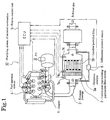
- Fig. 1 is a block diagram of an internal combustion engine exhaust gas purifying system according to an embodiment of the present invention;
- Fig. 2 is an illustration showing a set state of an internal combustion engine exhaust gas purifying system according to an embodiment of the present invention;
- Fig. 3 is an illustration showing a configuration of a controller of an internal-combustion-engine exhaust gas purifying system according to an embodiment of the present invention;
- Fig. 4 is an illustration showing a control flow by maximum-fuel-injection-quantity control means;
- Fig. 5(a) is an illustration showing the time series of the differential pressure between the upstream and downstream of a DPF when a judgment value for restriction is equal to a judgment value for regeneration in an internal-combustion-engine exhaust gas purifying system according to an embodiment of the present invention;
- Fig. 5(b) is an illustration showing the time series of the differential pressure between the upstream and downstream of a DPF when a judgment value for restriction is smaller than a judgment value for regeneration in an internal-combustion-engine exhaust gas purifying system according to an embodiment of the present invention; and
- Fig. 6 is an illustration showing the time series of the differential pressure between the upstream and downstream of a DPF in a conventional internal-combustion-engine exhaust gas purifying system.
-
- An exhaust gas purifying system of embodiments of the present invention are described below by using a exhaust gas purifying system having a continuous regenerating DPF system provided with a combination of an oxidation catalyst and a catalyst-provided filter as an example and referring to the accompanying drawings.
- Figs. 1 and 2 show a configuration of an exhaust gas purifying
system 10 of an internal combustion engine of the above embodiment. The exhaust gas purifyingsystem 10 of the internal combustion engine is constituted by including a continuous regenerating DPF system 3 which is set to an exhaust passage 2 of an engine (internal combustion engine) 1 and in which anoxidation catalyst 3a is set to the upstream side and a catalyst-provided filter (a catalyst-carried DPF) 3b is set to the downstream side. - The
oxidation catalyst 3a is formed by making a porous ceramic support with such a structure as honeycomb type carrying an oxidation catalyst such as platinum (Pt). The catalyst-providedfilter 3b is formed by a monolith-honeycomb wall-flow filter obtained by alternately closing the inlet and outlet of a porous ceramic honeycomb channel or a pannose filter obtained by laminating inorganic fiber such as alumina at random. The filter portion carries a catalyst such as platinum or cerium oxide. - Then, when using a monolith-honeycomb wall-flow filter for the catalyst-provided
filter 3b, a particulate matter (hereafter referred to as PM) contained in an exhaust gas is trapped by a porous ceramic wall. Moreover, when using a fibrous filter, the PM is trapped by inorganic fiber of the filter. - Then, to estimate the quantity of deposited PM of a catalyst-provided
filter 3b, a differential-pressure sensor 6 is set to a conduction tube connected to the upstream and downstream of a continuous regenerating DPF system 3. Moreover, for regeneration control of the catalyst-providedfilter 3b, afirst temperature sensor 7a is set to the upstream of anoxidation catalyst 3a at the exhaust gas inlet side, a second temperature sensor 7b is set between theoxidation catalyst 3a and catalyst-providedfilter 3b, and athird temperature sensor 7c is set to the exhaust gas exit side of the catalyst-providedfilter 3b. - Outputs of these sensors are input to a controller (ECU: engine control unit) 5 which performs not only general control of operations of the
engine 1 but also regeneration control of the catalyst-providedfilter 3b. Control signals output from thecontroller 5 control afuel injection system 4 of theengine 1. - Furthermore, in the case of the present invention, as shown in Fig. 3, DPF control means 51 of a
controller 5 is provided with maximum-fuel-injection-quantity restricting means 51C and fuelrestriction indicating means 51D in addition to collected-quantity estimation means 51A and regeneration control means 51B. - The collected-quantity estimation means 51A serves as means for estimating the quantity of collected PM in the catalyst-provided
filter 3b of the continuous regenerating DPF system 3. The quantity of collected PM is estimated by using the differential pressure ΔP between the upstream and the downstream of the catalyst-providedfilter 3b and relating the differential pressure ΔP with the quantity of collected PM. - Moreover, the regeneration control means 51B is executed when the differential pressure ΔP is equal to or more than a predetermined regeneration judgment value (threshold value) ΔPa. Though this control by the regeneration means is slightly different in the way of controlling by the types of the continuous regenerating DPF system 3, it raises an exhaust gas temperature by delaying (retarding) the timing of the main fuel injection of the
engine 1, performing a post injection, or an intake throttling. By raising an exhaust gas temperature, a temperature or an environment suitable for an oxidation and a removal of PM is realized to oxidize and remove the collected PM in the continuous regenerating DPF system 3. - Furthermore, the maximum-fuel-injection-
quantity restricting means 51C serves as means for restricting the maximum fuel injection quantity of anengine 1 when the quantity of collected PM estimated by the collected-quantity estimation means 51A is equal to or more than a predetermined judgment value. As shown by the flow in Fig. 4, this means is constituted so as to restrict the maximum fuel injection quantity when the differential pressure ΔP between the upstream and downstream of the catalyst-providedfilter 3b measured by the differential-pressure sensor 6 exceeds a predetermined judgment value for restriction (threshold value) ΔPb and restrict the maximum fuel injection quantity under the normal operation in cases other than the above case. Moreover, the means is constituted so that restriction of the maximum fuel injection quantity is completed when regeneration control is completed. - Furthermore, the fuel restriction indicating means 51D serves as means for warning or notifying an engine operator such as an automobile driver by means of a buzzer or voices that the maximum fuel injection quantity of the
engine 1 is restricted or the output of the engine is decreased due to restriction of the maximum fuel injection quantity when or while the maximum-fuel-injection-quantity control means 51C restricts the maximum fuel injection quantity of theengine 1. - The internal combustion engine exhaust
gas purifying system 10 having the above configuration restricts the maximum fuel injection quantity when PM is accumulated in the catalyst-providedfilter 3b of the continuous regenerating DPF system 3 approximately up to a limit value and the differential pressure ΔP exceeds the predetermined judgment value ΔPb for restriction. - Therefore, even if the
engine 1 shifts to a full-load operation state while the PM is accumulated approximately up to the limit value, it is possible to avoid that an exhaust gas quantity greatly increases and the differential pressure ΔP or an exhaust gas pressure greatly increases because the maximum fuel injection quantity is restricted to a value smaller than the normal maximum fuel injection quantity by the maximum-fuel-injection-quantity restricting means 51C. - Fig. 5 shows a case of performing a high-load operation (or full-load operation) at the point of time t3 close to the point of time t1 at which the differential pressure ΔP exceeds a judgment value ΔPa for regeneration. In this case, as shown in Fig. 5, the differential pressure ΔP becomes a continuous line showing a maximum-fuel-injection-quantity restriction in which the maximum value of the differential pressure ΔP is smaller than a dotted line showing the normal operation not restricted by the maximum-fuel-injection-
quantity restricting means 51C by ΔPe. Therefore, because it is possible to avoid the differential pressure ΔP and an exhaust gas pressure from greatly increasing, the influence on the continuous regenerating DPF system 3 depending on an operation condition is reduced, the body of theengine 1 is protected, and the fuel efficiency becomes advantageous. - Fig. 5(a) shows a case in which the judgment value ΔPb for restriction is smaller than the judgment value ΔPa for regeneration and in which the maximum fuel injection quantity is restricted from the point of time t2 when the differential pressure ΔP reaches the judgment value ΔPb for restriction and the regeneration control operation is started from the point of time t1 when the differential pressure ΔP reaches the judgment value ΔPa for regeneration.
- Fig. 5(b) shows a case in which the judgment value ΔPb for restriction when the maximum-fuel-injection-quantity restricting means 51C starts restriction of the maximum fuel injection quantity is the same as the judgment value ΔPa for regeneration when the regeneration control means 51B starts regeneration control and in which the maximum fuel injection quantity is restricted from the point of time t2 (=t1) when the differential pressure ΔP reaches the judgment value ΔPb (=ΔPa) for restriction and at the same time, regeneration control is also started.
- Then, because the fuel restriction indicating means 51D is set, it is possible to emit a warning by means of an indication, buzzer, or voices when or while the maximum fuel injection quantity is restricted because the differential pressure ΔP exceeds the judgment value ΔPb for restriction and notify a driver that the maximum fuel injection quantity is restricted.
- Therefore, the driver can previously know that the output of the
engine 1 is decreased compared to the case of the normal operation due to restriction of the maximum fuel injection quantity. - It is described above that a collected quantity is estimated by the collected-quantity estimation means 51A in accordance with the differential pressure ΔP between the upstream and downstream of the catalyst-provided
filter 3b. However, in this collected-quantity estimation means 51A, it is also possible to estimate the collected quantity by referring to previously input data map with a torque Q and an engine speed Ne showing an operation state of theengine 1, and a DPF inlet temperature measured by thefirst temperature sensor 7a, calculating a exhausted PM quantity and a purified PM quantity under the above operation state, calculating a PM quantity deposited on the catalyst-providedfilter 3b every time, and accumulating the PM quantities. Moreover, it is allowed to use another estimating method.
Claims (4)
- An internal combustion engine exhaust gas purifying system having a continuous regenerating diesel particulate filter system on the exhaust passage of an internal combustion engine to oxidize and remove collected particulate matter by performing the regenerating-mode operation when the quantity of collected particulate matter in a filter of the filter system for collecting the particulate matter becomes a predetermined judgment value or more, comprising:collected-quantity estimation means for estimating the quantity of collected particulate matter in the filter; andmaximum-fuel-injection-quantity restricting means for restricting the maximum fuel injection quantity of the internal combustion engine when the quantity of collected particulate matter estimated by the collected-quantity estimation means is the predetermined judgment value or more.
- The internal combustion engine exhaust gas purifying system according to claim 1, wherein
fuel restriction indicating means is included which indicates restriction of the maximum fuel injection quantity of an internal combustion engine when or while the maximum-fuel-injection-quantity restricting means restricts the maximum fuel injection quantity. - The internal combustion engine exhaust gas purifying system according to claim 1 or 2, wherein
the collected-quantity estimation means estimates the quantity of collected particulate matter in accordance with the differential pressure between the upstream and downstream of the filter. - The internal combustion engine exhaust gas purifying system according to any one of claims 1 to 3, wherein
the continuous regenerating diesel particulate filter system uses one of the following three systems: a system constituted by making the filter carrying a catalyst, a system constituted by setting an oxidation catalyst to the upstream side of the filter, and a system constituted by making the filter carrying a catalyst and setting an oxidation catalyst to the upstream side of the filter.
Applications Claiming Priority (2)
| Application Number | Priority Date | Filing Date | Title |
|---|---|---|---|
| JP2002270206 | 2002-09-17 | ||
| JP2002270206A JP4505176B2 (en) | 2002-09-17 | 2002-09-17 | Exhaust gas purification system for internal combustion engine |
Publications (3)
| Publication Number | Publication Date |
|---|---|
| EP1400673A2 true EP1400673A2 (en) | 2004-03-24 |
| EP1400673A3 EP1400673A3 (en) | 2006-12-06 |
| EP1400673B1 EP1400673B1 (en) | 2011-12-07 |
Family
ID=31944526
Family Applications (1)
| Application Number | Title | Priority Date | Filing Date |
|---|---|---|---|
| EP03020244A Expired - Fee Related EP1400673B1 (en) | 2002-09-17 | 2003-09-06 | Internal combustion engine exhaust gas purifying system |
Country Status (3)
| Country | Link |
|---|---|
| US (1) | US7210285B2 (en) |
| EP (1) | EP1400673B1 (en) |
| JP (1) | JP4505176B2 (en) |
Cited By (3)
| Publication number | Priority date | Publication date | Assignee | Title |
|---|---|---|---|---|
| EP1726807A1 (en) * | 2005-05-13 | 2006-11-29 | HONDA MOTOR CO., Ltd. | Engine output control system for internal combustion engine |
| US7836687B2 (en) | 2006-12-21 | 2010-11-23 | Cummins Inc. | Soot filter regeneration software, methods and systems |
| CN103806985A (en) * | 2012-11-15 | 2014-05-21 | 株式会社可莫科技 | Warming device, extended warming device, filter regenerating device and exhaust purification device |
Families Citing this family (19)
| Publication number | Priority date | Publication date | Assignee | Title |
|---|---|---|---|---|
| KR100469066B1 (en) * | 2003-04-14 | 2005-02-02 | 에스케이 주식회사 | A catalytic filter for the removal of soot particulates from diesel engine and method of making the same |
| JP4508714B2 (en) * | 2004-04-23 | 2010-07-21 | Udトラックス株式会社 | Exhaust purification device |
| JPWO2006004175A1 (en) * | 2004-06-30 | 2008-04-24 | イビデン株式会社 | Exhaust purification device |
| JP2006125206A (en) | 2004-10-26 | 2006-05-18 | Ict:Kk | Purification method and device for internal combustion engine exhaust gas |
| JP4580803B2 (en) * | 2005-03-31 | 2010-11-17 | キャタピラー エス エー アール エル | Clogging notification device for exhaust gas purification device for internal combustion engine |
| JP4434061B2 (en) * | 2005-04-08 | 2010-03-17 | トヨタ自動車株式会社 | Exhaust gas purification device for internal combustion engine |
| US7533524B2 (en) * | 2005-05-18 | 2009-05-19 | Cummins Inc. | Method and apparatus for soot filter catalyst temperature control with oxygen flow constraint |
| JP5639337B2 (en) | 2006-03-30 | 2014-12-10 | ユミコア日本触媒株式会社 | Internal combustion engine exhaust gas purification method |
| TWI423848B (en) | 2006-07-13 | 2014-01-21 | Umicore Shokubai Japan Co Ltd | Method for purification of exhaust gas from internal-combustion engine |
| US7558668B2 (en) * | 2007-11-30 | 2009-07-07 | Caterpillar Inc. | Exhaust system having temperature sensor verification |
| DE102008004209A1 (en) * | 2008-01-14 | 2009-07-16 | Robert Bosch Gmbh | Method for operating a drive train of a vehicle and device for carrying out the method |
| US8407985B2 (en) * | 2009-07-28 | 2013-04-02 | International Engine Intellectual Property Company, Llc | Method of monitoring hydrocarbon levels in a diesel particulate filter |
| JP5533260B2 (en) * | 2010-05-25 | 2014-06-25 | いすゞ自動車株式会社 | DPF system |
| US8444730B2 (en) * | 2010-09-27 | 2013-05-21 | Ford Global Technologies, Llc | Even-loading DPF and regeneration thereof |
| JP6311731B2 (en) * | 2016-01-27 | 2018-04-18 | トヨタ自動車株式会社 | Exhaust gas purification device for internal combustion engine |
| JP6365560B2 (en) * | 2016-01-27 | 2018-08-01 | トヨタ自動車株式会社 | Exhaust gas purification device for internal combustion engine |
| CN109026288B (en) * | 2018-06-28 | 2019-09-03 | 常熟理工学院 | A method of the discharge of Light-duty Vehicle particulate matter quantity is reduced based on vehicle behavior |
| JP7063190B2 (en) * | 2018-08-21 | 2022-05-09 | トヨタ自動車株式会社 | Vehicle control device |
| JP7304244B2 (en) * | 2019-09-05 | 2023-07-06 | 株式会社Subaru | engine controller |
Family Cites Families (12)
| Publication number | Priority date | Publication date | Assignee | Title |
|---|---|---|---|---|
| US4211075A (en) * | 1978-10-19 | 1980-07-08 | General Motors Corporation | Diesel engine exhaust particulate filter with intake throttling incineration control |
| US4535588A (en) * | 1979-06-12 | 1985-08-20 | Nippon Soken, Inc. | Carbon particulates cleaning device for diesel engine |
| DE8215874U1 (en) * | 1982-06-01 | 1982-10-28 | Forschungsgesellschaft für Energietechnik und Verbrennungsmotoren mbH, 5100 Aachen | DEVICE FOR TREATING DIESEL ENGINE EXHAUST GASES TO REDUCE PARTICLE EMISSION |
| IT1185663B (en) * | 1984-09-14 | 1987-11-12 | Volkswagen Ag | PROCEDURE AND DEVICE FOR ELIMINATING THE SOLID COMPONENTS CONTAINED IN THE EXHAUST GASES OF INTERNAL COMBUSTION ENGINES |
| US4902487A (en) * | 1988-05-13 | 1990-02-20 | Johnson Matthey, Inc. | Treatment of diesel exhaust gases |
| JPH0441914A (en) * | 1990-06-01 | 1992-02-12 | Nissan Motor Co Ltd | Exhaust gas processor for internal combustion engine |
| JP3899534B2 (en) * | 1995-08-14 | 2007-03-28 | トヨタ自動車株式会社 | Exhaust gas purification method for diesel engine |
| JP2002106327A (en) | 2000-10-02 | 2002-04-10 | Nissan Motor Co Ltd | Control device of internal combustion engine |
| DE50001415D1 (en) * | 2000-11-03 | 2003-04-10 | Ford Global Tech Inc | Process for the regeneration of the particle filter of a diesel engine |
| JP3747778B2 (en) * | 2000-12-14 | 2006-02-22 | トヨタ自動車株式会社 | Exhaust gas purification device for internal combustion engine |
| US6622480B2 (en) * | 2001-02-21 | 2003-09-23 | Isuzu Motors Limited | Diesel particulate filter unit and regeneration control method of the same |
| DE10108720A1 (en) * | 2001-02-23 | 2002-09-05 | Bosch Gmbh Robert | Method and device for controlling an internal combustion engine |
-
2002
- 2002-09-17 JP JP2002270206A patent/JP4505176B2/en not_active Expired - Fee Related
-
2003
- 2003-09-06 EP EP03020244A patent/EP1400673B1/en not_active Expired - Fee Related
- 2003-09-10 US US10/658,259 patent/US7210285B2/en not_active Expired - Fee Related
Non-Patent Citations (1)
| Title |
|---|
| None |
Cited By (4)
| Publication number | Priority date | Publication date | Assignee | Title |
|---|---|---|---|---|
| EP1726807A1 (en) * | 2005-05-13 | 2006-11-29 | HONDA MOTOR CO., Ltd. | Engine output control system for internal combustion engine |
| US7836687B2 (en) | 2006-12-21 | 2010-11-23 | Cummins Inc. | Soot filter regeneration software, methods and systems |
| CN103806985A (en) * | 2012-11-15 | 2014-05-21 | 株式会社可莫科技 | Warming device, extended warming device, filter regenerating device and exhaust purification device |
| CN103806985B (en) * | 2012-11-15 | 2017-04-05 | 株式会社可莫科技 | Heat riser, extension heat riser, filter regenerating apparatus and emission-control equipment |
Also Published As
| Publication number | Publication date |
|---|---|
| US7210285B2 (en) | 2007-05-01 |
| EP1400673B1 (en) | 2011-12-07 |
| US20040055287A1 (en) | 2004-03-25 |
| EP1400673A3 (en) | 2006-12-06 |
| JP2004108207A (en) | 2004-04-08 |
| JP4505176B2 (en) | 2010-07-21 |
Similar Documents
| Publication | Publication Date | Title |
|---|---|---|
| US7210285B2 (en) | Internal combustion engine exhaust gas purifying system | |
| EP1953356B1 (en) | Method for control of exhaust gas purification system, and exhaust gas purification system | |
| EP1905991B1 (en) | Control method of exhaust gas purification system and exhaust gas purification system | |
| EP1510671B1 (en) | Exhaust gas purifying method | |
| US7421837B2 (en) | Control method for an exhaust gas purification system and an exhaust gas purification system | |
| US7721534B2 (en) | Control method for an exhaust gas purification system and an exhaust gas purification system | |
| US7845165B2 (en) | Exhaust gas purifying system | |
| JP4385775B2 (en) | Exhaust gas purification device for internal combustion engine | |
| US8322130B2 (en) | Method for controlling exhaust gas purification system and exhaust gas purification system | |
| JP4140640B2 (en) | Exhaust gas purification method and exhaust gas purification system | |
| EP1538311A1 (en) | Exhaust gas purifying method and exhaust gas purifying system | |
| EP1400664B1 (en) | Exhaust gas purifying method and exhaust gas purifying system | |
| US20050217245A1 (en) | Control method for an exhaust gas purification system and an exhaust gas purification system | |
| US7451593B2 (en) | Exhaust gas cleaning method and exhaust gas cleaning system | |
| JP4363289B2 (en) | Exhaust gas purification device for internal combustion engine | |
| JP4333180B2 (en) | Exhaust gas purification system | |
| JP2003020933A (en) | Exhaust emission control device for internal combustion engine | |
| JP4070681B2 (en) | Exhaust purification device | |
| JP4001235B2 (en) | Exhaust purification control method and exhaust purification apparatus |
Legal Events
| Date | Code | Title | Description |
|---|---|---|---|
| PUAI | Public reference made under article 153(3) epc to a published international application that has entered the european phase |
Free format text: ORIGINAL CODE: 0009012 |
|
| AK | Designated contracting states |
Kind code of ref document: A2 Designated state(s): AT BE BG CH CY CZ DE DK EE ES FI FR GB GR HU IE IT LI LU MC NL PT RO SE SI SK TR |
|
| AX | Request for extension of the european patent |
Extension state: AL LT LV MK |
|
| PUAL | Search report despatched |
Free format text: ORIGINAL CODE: 0009013 |
|
| AK | Designated contracting states |
Kind code of ref document: A3 Designated state(s): AT BE BG CH CY CZ DE DK EE ES FI FR GB GR HU IE IT LI LU MC NL PT RO SE SI SK TR |
|
| AX | Request for extension of the european patent |
Extension state: AL LT LV MK |
|
| RIC1 | Information provided on ipc code assigned before grant |
Ipc: F01N 9/00 20060101ALI20061030BHEP Ipc: F01N 3/023 20060101ALI20061030BHEP Ipc: F02D 41/40 20060101ALI20061030BHEP Ipc: F02D 41/02 20060101AFI20031205BHEP |
|
| 17P | Request for examination filed |
Effective date: 20070412 |
|
| AKX | Designation fees paid |
Designated state(s): DE FR GB IT |
|
| 17Q | First examination report despatched |
Effective date: 20080304 |
|
| GRAP | Despatch of communication of intention to grant a patent |
Free format text: ORIGINAL CODE: EPIDOSNIGR1 |
|
| GRAC | Information related to communication of intention to grant a patent modified |
Free format text: ORIGINAL CODE: EPIDOSCIGR1 |
|
| GRAS | Grant fee paid |
Free format text: ORIGINAL CODE: EPIDOSNIGR3 |
|
| GRAA | (expected) grant |
Free format text: ORIGINAL CODE: 0009210 |
|
| AK | Designated contracting states |
Kind code of ref document: B1 Designated state(s): DE FR GB IT |
|
| REG | Reference to a national code |
Ref country code: GB Ref legal event code: FG4D |
|
| REG | Reference to a national code |
Ref country code: DE Ref legal event code: R096 Ref document number: 60339316 Country of ref document: DE Effective date: 20120308 |
|
| PLBE | No opposition filed within time limit |
Free format text: ORIGINAL CODE: 0009261 |
|
| STAA | Information on the status of an ep patent application or granted ep patent |
Free format text: STATUS: NO OPPOSITION FILED WITHIN TIME LIMIT |
|
| 26N | No opposition filed |
Effective date: 20120910 |
|
| PG25 | Lapsed in a contracting state [announced via postgrant information from national office to epo] |
Ref country code: IT Free format text: LAPSE BECAUSE OF FAILURE TO SUBMIT A TRANSLATION OF THE DESCRIPTION OR TO PAY THE FEE WITHIN THE PRESCRIBED TIME-LIMIT Effective date: 20111207 |
|
| REG | Reference to a national code |
Ref country code: DE Ref legal event code: R097 Ref document number: 60339316 Country of ref document: DE Effective date: 20120910 |
|
| REG | Reference to a national code |
Ref country code: FR Ref legal event code: PLFP Year of fee payment: 14 |
|
| PGFP | Annual fee paid to national office [announced via postgrant information from national office to epo] |
Ref country code: GB Payment date: 20160831 Year of fee payment: 14 Ref country code: DE Payment date: 20160831 Year of fee payment: 14 |
|
| PGFP | Annual fee paid to national office [announced via postgrant information from national office to epo] |
Ref country code: FR Payment date: 20160816 Year of fee payment: 14 |
|
| REG | Reference to a national code |
Ref country code: DE Ref legal event code: R119 Ref document number: 60339316 Country of ref document: DE |
|
| GBPC | Gb: european patent ceased through non-payment of renewal fee |
Effective date: 20170906 |
|
| REG | Reference to a national code |
Ref country code: FR Ref legal event code: ST Effective date: 20180531 |
|
| PG25 | Lapsed in a contracting state [announced via postgrant information from national office to epo] |
Ref country code: DE Free format text: LAPSE BECAUSE OF NON-PAYMENT OF DUE FEES Effective date: 20180404 Ref country code: GB Free format text: LAPSE BECAUSE OF NON-PAYMENT OF DUE FEES Effective date: 20170906 |
|
| PG25 | Lapsed in a contracting state [announced via postgrant information from national office to epo] |
Ref country code: FR Free format text: LAPSE BECAUSE OF NON-PAYMENT OF DUE FEES Effective date: 20171002 |