EP1400603A1 - Crawler bushing and method and device for producing the same - Google Patents
Crawler bushing and method and device for producing the same Download PDFInfo
- Publication number
- EP1400603A1 EP1400603A1 EP01938559A EP01938559A EP1400603A1 EP 1400603 A1 EP1400603 A1 EP 1400603A1 EP 01938559 A EP01938559 A EP 01938559A EP 01938559 A EP01938559 A EP 01938559A EP 1400603 A1 EP1400603 A1 EP 1400603A1
- Authority
- EP
- European Patent Office
- Prior art keywords
- circumferential surface
- cooling
- track bushing
- outer circumferential
- inner circumferential
- Prior art date
- Legal status (The legal status is an assumption and is not a legal conclusion. Google has not performed a legal analysis and makes no representation as to the accuracy of the status listed.)
- Granted
Links
- 238000000034 method Methods 0.000 title claims description 102
- 238000001816 cooling Methods 0.000 claims abstract description 338
- 238000010791 quenching Methods 0.000 claims abstract description 206
- 230000000171 quenching effect Effects 0.000 claims abstract description 200
- 239000002826 coolant Substances 0.000 claims abstract description 108
- 238000010438 heat treatment Methods 0.000 claims description 266
- 230000006698 induction Effects 0.000 claims description 175
- 239000000463 material Substances 0.000 claims description 71
- 238000005192 partition Methods 0.000 claims description 71
- 230000008569 process Effects 0.000 claims description 40
- XLYOFNOQVPJJNP-UHFFFAOYSA-N water Substances O XLYOFNOQVPJJNP-UHFFFAOYSA-N 0.000 claims description 38
- 238000007789 sealing Methods 0.000 claims description 34
- 239000010410 layer Substances 0.000 claims description 32
- 238000005496 tempering Methods 0.000 claims description 30
- 239000011810 insulating material Substances 0.000 claims description 18
- 229910000734 martensite Inorganic materials 0.000 claims description 17
- 229910000859 α-Fe Inorganic materials 0.000 claims description 16
- 229910001562 pearlite Inorganic materials 0.000 claims description 15
- VYPSYNLAJGMNEJ-UHFFFAOYSA-N Silicium dioxide Chemical compound O=[Si]=O VYPSYNLAJGMNEJ-UHFFFAOYSA-N 0.000 claims description 14
- 229910001563 bainite Inorganic materials 0.000 claims description 14
- 230000000694 effects Effects 0.000 claims description 14
- 239000002344 surface layer Substances 0.000 claims description 14
- 238000009792 diffusion process Methods 0.000 claims description 11
- 239000002244 precipitate Substances 0.000 claims description 11
- 229910052581 Si3N4 Inorganic materials 0.000 claims description 6
- PNEYBMLMFCGWSK-UHFFFAOYSA-N aluminium oxide Inorganic materials [O-2].[O-2].[O-2].[Al+3].[Al+3] PNEYBMLMFCGWSK-UHFFFAOYSA-N 0.000 claims description 6
- 229910052593 corundum Inorganic materials 0.000 claims description 6
- 238000003825 pressing Methods 0.000 claims description 6
- 229910001845 yogo sapphire Inorganic materials 0.000 claims description 6
- 229910052681 coesite Inorganic materials 0.000 claims description 5
- 229910052906 cristobalite Inorganic materials 0.000 claims description 5
- 238000007599 discharging Methods 0.000 claims description 5
- 239000000377 silicon dioxide Substances 0.000 claims description 5
- 229910052682 stishovite Inorganic materials 0.000 claims description 5
- 229910052905 tridymite Inorganic materials 0.000 claims description 5
- 229910045601 alloy Inorganic materials 0.000 claims description 4
- 239000000956 alloy Substances 0.000 claims description 4
- 239000000919 ceramic Substances 0.000 claims description 4
- 229910000914 Mn alloy Inorganic materials 0.000 claims description 3
- 230000005290 antiferromagnetic effect Effects 0.000 claims description 3
- KZHJGOXRZJKJNY-UHFFFAOYSA-N dioxosilane;oxo(oxoalumanyloxy)alumane Chemical compound O=[Si]=O.O=[Si]=O.O=[Al]O[Al]=O.O=[Al]O[Al]=O.O=[Al]O[Al]=O KZHJGOXRZJKJNY-UHFFFAOYSA-N 0.000 claims description 3
- 229910052863 mullite Inorganic materials 0.000 claims description 3
- 239000012212 insulator Substances 0.000 claims description 2
- 239000007788 liquid Substances 0.000 claims description 2
- 238000012544 monitoring process Methods 0.000 claims description 2
- 239000007921 spray Substances 0.000 description 41
- 235000019589 hardness Nutrition 0.000 description 17
- 230000001965 increasing effect Effects 0.000 description 13
- 230000035515 penetration Effects 0.000 description 12
- 239000000498 cooling water Substances 0.000 description 11
- 238000012360 testing method Methods 0.000 description 11
- 238000009826 distribution Methods 0.000 description 9
- 229910000831 Steel Inorganic materials 0.000 description 8
- XEEYBQQBJWHFJM-UHFFFAOYSA-N iron Substances [Fe] XEEYBQQBJWHFJM-UHFFFAOYSA-N 0.000 description 8
- 238000004519 manufacturing process Methods 0.000 description 8
- 239000010959 steel Substances 0.000 description 8
- 238000007669 thermal treatment Methods 0.000 description 7
- 238000005259 measurement Methods 0.000 description 6
- 230000002265 prevention Effects 0.000 description 6
- 230000009467 reduction Effects 0.000 description 6
- 239000000725 suspension Substances 0.000 description 6
- 239000010425 asbestos Substances 0.000 description 5
- 230000007246 mechanism Effects 0.000 description 5
- 229910052895 riebeckite Inorganic materials 0.000 description 5
- 239000004925 Acrylic resin Substances 0.000 description 4
- 229920000178 Acrylic resin Polymers 0.000 description 4
- 239000000428 dust Substances 0.000 description 4
- 230000006872 improvement Effects 0.000 description 4
- 238000010586 diagram Methods 0.000 description 3
- 230000003028 elevating effect Effects 0.000 description 3
- 229910052742 iron Inorganic materials 0.000 description 3
- 239000002184 metal Substances 0.000 description 3
- 229910052751 metal Inorganic materials 0.000 description 3
- 229910000975 Carbon steel Inorganic materials 0.000 description 2
- RYGMFSIKBFXOCR-UHFFFAOYSA-N Copper Chemical compound [Cu] RYGMFSIKBFXOCR-UHFFFAOYSA-N 0.000 description 2
- 229910000954 Medium-carbon steel Inorganic materials 0.000 description 2
- 230000002159 abnormal effect Effects 0.000 description 2
- 230000008901 benefit Effects 0.000 description 2
- 230000005540 biological transmission Effects 0.000 description 2
- 229910052799 carbon Inorganic materials 0.000 description 2
- 239000010962 carbon steel Substances 0.000 description 2
- 230000015556 catabolic process Effects 0.000 description 2
- 230000000052 comparative effect Effects 0.000 description 2
- 238000010276 construction Methods 0.000 description 2
- 238000007796 conventional method Methods 0.000 description 2
- 229910052802 copper Inorganic materials 0.000 description 2
- 239000010949 copper Substances 0.000 description 2
- 230000006378 damage Effects 0.000 description 2
- 230000007423 decrease Effects 0.000 description 2
- 230000003247 decreasing effect Effects 0.000 description 2
- 238000006731 degradation reaction Methods 0.000 description 2
- 230000006866 deterioration Effects 0.000 description 2
- 238000011156 evaluation Methods 0.000 description 2
- 238000009413 insulation Methods 0.000 description 2
- 239000000314 lubricant Substances 0.000 description 2
- 230000014759 maintenance of location Effects 0.000 description 2
- 238000012986 modification Methods 0.000 description 2
- 230000004048 modification Effects 0.000 description 2
- 239000010453 quartz Substances 0.000 description 2
- 238000011160 research Methods 0.000 description 2
- 239000004576 sand Substances 0.000 description 2
- 238000002791 soaking Methods 0.000 description 2
- 238000005507 spraying Methods 0.000 description 2
- 238000011179 visual inspection Methods 0.000 description 2
- OKTJSMMVPCPJKN-UHFFFAOYSA-N Carbon Chemical compound [C] OKTJSMMVPCPJKN-UHFFFAOYSA-N 0.000 description 1
- 229910001035 Soft ferrite Inorganic materials 0.000 description 1
- 230000002411 adverse Effects 0.000 description 1
- 229910000963 austenitic stainless steel Inorganic materials 0.000 description 1
- 238000006243 chemical reaction Methods 0.000 description 1
- 229910052804 chromium Inorganic materials 0.000 description 1
- 238000012790 confirmation Methods 0.000 description 1
- 238000005336 cracking Methods 0.000 description 1
- 230000003111 delayed effect Effects 0.000 description 1
- 238000013461 design Methods 0.000 description 1
- 238000011161 development Methods 0.000 description 1
- 238000006073 displacement reaction Methods 0.000 description 1
- 238000009661 fatigue test Methods 0.000 description 1
- 230000005294 ferromagnetic effect Effects 0.000 description 1
- 230000017525 heat dissipation Effects 0.000 description 1
- 230000001939 inductive effect Effects 0.000 description 1
- 238000007689 inspection Methods 0.000 description 1
- 229910000953 kanthal Inorganic materials 0.000 description 1
- 238000011031 large-scale manufacturing process Methods 0.000 description 1
- 229910052748 manganese Inorganic materials 0.000 description 1
- 229910001092 metal group alloy Inorganic materials 0.000 description 1
- 150000002739 metals Chemical class 0.000 description 1
- 229910052750 molybdenum Inorganic materials 0.000 description 1
- 229910001120 nichrome Inorganic materials 0.000 description 1
- 229910052759 nickel Inorganic materials 0.000 description 1
- 230000003647 oxidation Effects 0.000 description 1
- 238000007254 oxidation reaction Methods 0.000 description 1
- 230000005298 paramagnetic effect Effects 0.000 description 1
- 230000002093 peripheral effect Effects 0.000 description 1
- 238000002360 preparation method Methods 0.000 description 1
- 230000005855 radiation Effects 0.000 description 1
- 230000000452 restraining effect Effects 0.000 description 1
- 238000000926 separation method Methods 0.000 description 1
- 230000035939 shock Effects 0.000 description 1
- 230000001629 suppression Effects 0.000 description 1
- 238000012546 transfer Methods 0.000 description 1
- 230000009466 transformation Effects 0.000 description 1
Images








Classifications
-
- B—PERFORMING OPERATIONS; TRANSPORTING
- B62—LAND VEHICLES FOR TRAVELLING OTHERWISE THAN ON RAILS
- B62D—MOTOR VEHICLES; TRAILERS
- B62D55/00—Endless track vehicles
- B62D55/08—Endless track units; Parts thereof
- B62D55/18—Tracks
- B62D55/20—Tracks of articulated type, e.g. chains
- B62D55/205—Connections between track links
- B62D55/21—Links connected by transverse pivot pins
-
- C—CHEMISTRY; METALLURGY
- C21—METALLURGY OF IRON
- C21D—MODIFYING THE PHYSICAL STRUCTURE OF FERROUS METALS; GENERAL DEVICES FOR HEAT TREATMENT OF FERROUS OR NON-FERROUS METALS OR ALLOYS; MAKING METAL MALLEABLE, e.g. BY DECARBURISATION OR TEMPERING
- C21D9/00—Heat treatment, e.g. annealing, hardening, quenching or tempering, adapted for particular articles; Furnaces therefor
-
- C—CHEMISTRY; METALLURGY
- C21—METALLURGY OF IRON
- C21D—MODIFYING THE PHYSICAL STRUCTURE OF FERROUS METALS; GENERAL DEVICES FOR HEAT TREATMENT OF FERROUS OR NON-FERROUS METALS OR ALLOYS; MAKING METAL MALLEABLE, e.g. BY DECARBURISATION OR TEMPERING
- C21D1/00—General methods or devices for heat treatment, e.g. annealing, hardening, quenching or tempering
- C21D1/18—Hardening; Quenching with or without subsequent tempering
-
- C—CHEMISTRY; METALLURGY
- C21—METALLURGY OF IRON
- C21D—MODIFYING THE PHYSICAL STRUCTURE OF FERROUS METALS; GENERAL DEVICES FOR HEAT TREATMENT OF FERROUS OR NON-FERROUS METALS OR ALLOYS; MAKING METAL MALLEABLE, e.g. BY DECARBURISATION OR TEMPERING
- C21D1/00—General methods or devices for heat treatment, e.g. annealing, hardening, quenching or tempering
- C21D1/34—Methods of heating
- C21D1/42—Induction heating
-
- C—CHEMISTRY; METALLURGY
- C21—METALLURGY OF IRON
- C21D—MODIFYING THE PHYSICAL STRUCTURE OF FERROUS METALS; GENERAL DEVICES FOR HEAT TREATMENT OF FERROUS OR NON-FERROUS METALS OR ALLOYS; MAKING METAL MALLEABLE, e.g. BY DECARBURISATION OR TEMPERING
- C21D1/00—General methods or devices for heat treatment, e.g. annealing, hardening, quenching or tempering
- C21D1/62—Quenching devices
-
- C—CHEMISTRY; METALLURGY
- C21—METALLURGY OF IRON
- C21D—MODIFYING THE PHYSICAL STRUCTURE OF FERROUS METALS; GENERAL DEVICES FOR HEAT TREATMENT OF FERROUS OR NON-FERROUS METALS OR ALLOYS; MAKING METAL MALLEABLE, e.g. BY DECARBURISATION OR TEMPERING
- C21D9/00—Heat treatment, e.g. annealing, hardening, quenching or tempering, adapted for particular articles; Furnaces therefor
- C21D9/08—Heat treatment, e.g. annealing, hardening, quenching or tempering, adapted for particular articles; Furnaces therefor for tubular bodies or pipes
-
- C—CHEMISTRY; METALLURGY
- C21—METALLURGY OF IRON
- C21D—MODIFYING THE PHYSICAL STRUCTURE OF FERROUS METALS; GENERAL DEVICES FOR HEAT TREATMENT OF FERROUS OR NON-FERROUS METALS OR ALLOYS; MAKING METAL MALLEABLE, e.g. BY DECARBURISATION OR TEMPERING
- C21D9/00—Heat treatment, e.g. annealing, hardening, quenching or tempering, adapted for particular articles; Furnaces therefor
- C21D9/08—Heat treatment, e.g. annealing, hardening, quenching or tempering, adapted for particular articles; Furnaces therefor for tubular bodies or pipes
- C21D9/085—Cooling or quenching
-
- C—CHEMISTRY; METALLURGY
- C21—METALLURGY OF IRON
- C21D—MODIFYING THE PHYSICAL STRUCTURE OF FERROUS METALS; GENERAL DEVICES FOR HEAT TREATMENT OF FERROUS OR NON-FERROUS METALS OR ALLOYS; MAKING METAL MALLEABLE, e.g. BY DECARBURISATION OR TEMPERING
- C21D9/00—Heat treatment, e.g. annealing, hardening, quenching or tempering, adapted for particular articles; Furnaces therefor
- C21D9/08—Heat treatment, e.g. annealing, hardening, quenching or tempering, adapted for particular articles; Furnaces therefor for tubular bodies or pipes
- C21D9/14—Heat treatment, e.g. annealing, hardening, quenching or tempering, adapted for particular articles; Furnaces therefor for tubular bodies or pipes wear-resistant or pressure-resistant pipes
-
- C—CHEMISTRY; METALLURGY
- C21—METALLURGY OF IRON
- C21D—MODIFYING THE PHYSICAL STRUCTURE OF FERROUS METALS; GENERAL DEVICES FOR HEAT TREATMENT OF FERROUS OR NON-FERROUS METALS OR ALLOYS; MAKING METAL MALLEABLE, e.g. BY DECARBURISATION OR TEMPERING
- C21D2221/00—Treating localised areas of an article
- C21D2221/10—Differential treatment of inner with respect to outer regions, e.g. core and periphery, respectively
-
- Y—GENERAL TAGGING OF NEW TECHNOLOGICAL DEVELOPMENTS; GENERAL TAGGING OF CROSS-SECTIONAL TECHNOLOGIES SPANNING OVER SEVERAL SECTIONS OF THE IPC; TECHNICAL SUBJECTS COVERED BY FORMER USPC CROSS-REFERENCE ART COLLECTIONS [XRACs] AND DIGESTS
- Y02—TECHNOLOGIES OR APPLICATIONS FOR MITIGATION OR ADAPTATION AGAINST CLIMATE CHANGE
- Y02P—CLIMATE CHANGE MITIGATION TECHNOLOGIES IN THE PRODUCTION OR PROCESSING OF GOODS
- Y02P10/00—Technologies related to metal processing
- Y02P10/25—Process efficiency
Definitions
- the invention relates to a track bushing for use in construction machines such as bulldozers, and a method and apparatus for producing the same. More particularly, the invention relates to a track bushing excellent in wear resistance and impact fatigue resistance, and a method and apparatus for producing such a track bushing at low cost, by use of a simpler means.
- a known crawler belt 51 for use in a construction machine or the like comprises assemblage of parts such as shown in Fig. 23.
- a track bushing 52 is required to have wear resistance at its inner and outer circumferential surfaces as well as high strength and toughness as a bushing, because it engages sprocket teeth for transmitting rotational movement from final reduction gears and functions to rotate the crawler belt 51.
- pre-lubricated crawler belts containing a lubricant in a gap between a track pin 53 and the track bushing 52 in order to prevent occurrence of seizure between them.
- the carburization method 1 ⁇ produces a track bushing having good functionality as a pre-lubricated bushing because the end faces of the bushing are uniformly carburization hardened, but presents the problem that it takes a long time to carburize because the carburization-hardened case needs to be deepened in order to increase the wear resistance of the outer circumferential cylindrical surface, and use of a large amount of carburization gas leads to increased cost.
- the depth of the hardened case must be great in view of strength and wear resistance, which results in a decrease in yield and high cost.
- the induction hardening method 2 ⁇ has been improved over the carburization method 1 ⁇ in terms of cost, but disadvantageously requires two quenching processes, i.e., quenching from the inner and outer circumferential surfaces, so that it cannot be regarded as a satisfactory thermal treatment having improved productivity and cost performance. Additionally, in this induction hardening method, irregularities and omissions in quenching of the end faces of the pre-lubricated track bushing are unavoidable and therefore there arises a problem in ensuring the wear resistance of the end face serving as a dust seal face for preventing penetration of earth and sand into the inner circumference section of the bushing.
- the method 3 ⁇ in which the outer circumferential surface is cooled after preceding cooling of the inner circumferential surface, has the advantage that a track bushing excellent in wear resistance can be produced at very low cost by one quenching operation, but presents the drawback that if spray cooling is employed for cooling the inner circumferential surface of a cylindrical tube of small inside diameter, satisfactory cooling performance and uniformity cannot be ensured, because a surface to be cooled is usually positioned at a distance apart from the nozzle, the distance being about 10 times the bore diameter of the nozzle, in order to obtain an increased heat transfer coefficient and because the ability to discharge spray water is poor.
- Quenching irregularities in the inner circumferential surface are unavoidable particularly where the method is applied to a track bushing having a very small inside diameter or where, with the intention of attaining increased productivity, the inner circumferential surfaces of two or more track bushings are quenched with their end faces overlapping each other. As a result, a satisfactory improvement in productivity nor cost reduction cannot be achieved.
- the invention has been directed to overcoming the foregoing drawbacks and a primary object of the invention is therefore to provide a track bushing and its production method and apparatus, according to which inner circumferential surface cooling is carried out by an intratube laminar flow of a cooling medium so that a quenched case can be uniformly formed in the inner circumferential surface of a track bushing of small inside diameter or two or more track bushings being quenched in an overlapped manner, thereby achieving improvements over the carburization treatment and the induction quenching treatment in terms of productivity and cost.
- Another object of the invention is to provide a track bushing production method and apparatus which are applicable to a pre-lubricated track bushing by virtue of the arrangement in which the inner circumferential surface of the bushing is cooled by an intratube laminar flow in order to completely shut off a leakage of the cooling medium for the inner circumferential surface from the gap between each end face of the track bushing and a partition jig for water-flow separation which is in contact with each end face of the bushing, and in which the speed of cooling from the inner circumferential surface in the neighborhood of both end faces of the bushing is slowed down by the partition jigs, thereby quench-hardening the flat sealing portions of the end faces.
- the invention can obviate the need for heating from the inner circumferential surface and enables reliable quenching of the inner circumferential surface of a long cylindrical steel pipe of small inside diameter, and therefore another object of the invention is to provide a method and apparatus for producing, at low cost, a cylindrical part for general purpose which requires wear resistance and strength.
- Still another object of the invention is to provide a method and apparatus for producing, at low cost, a track bushing having satisfactory toughness and wear resistance, in which a tempering treatment applied to a track bushing after quenching is eliminated or simplified.
- This method and apparatus are designed such that, in a series of quenching operations wherein preceding cooling from the inner circumferential surface is effected while carrying out induction heating from the outer circumferential surface and after an elapse of a specified time, cooling from the outer circumferential surface is carried out, a series of quenching processes is added in which during the additional induction heating from the outer circumferential surface or during the time from when the induction heating is stopped until when the outer circumferential surface cooling starts, the cooling from the inner circumferential surface is stopped for a specified time; the inner circumferential surface is tempered within a short time by heat diffusion from the outer circumferential surface to the inner circumferential surface; and the inner circumferential surface is cooled again, and after an elapse of a specified time, the cooling from
- a first aspect of the invention resides in that the surface layers of flat sealing portions at both end faces of a track bushing are respectively quench-hardened to a depth no less than one-half the wall thickness of the bushing from the outer circumferential surface, by use of partition jigs used for separating an inner circumferential cooling medium from an outer circumferential cooling medium such that when cooling the inner circumferential surface of the track bushing, the cooling of the inner circumferential surface is speeded down in the neighborhood of both end faces of the bushing and both end faces are effectively heated by additional induction heating from the outer circumferential surface.
- another partition jig having the same principle is interposed between two track bushings, whereby pre-lubricated track bushings requiring end face quench-hardened cases can be quenched and, in consequence, considerably improved productivity can be achieved.
- the additional induction heating from the outer circumferential surface is effected such that after the track bushing is entirely heated to a temperature at which the bushing is quenchable (quenching temperature), the outer circumferential surface is heated so as to be kept at the quenching temperature (this heating process is called "additional heating"), while the inner circumferential surface of the track bushing being subjected to preceding cooling, or alternatively such that a series of quenching processes is applied, as described later, to a track bushing which has been shifted to a quenching system after heated by a separated heating furnace or induction heating system.
- additional heating is as follows.
- a method of producing a track bushing according to the first aspect of the invention wherein, in a series of quenching processes in which by use of a quenching system capable of carrying out induction heating from the outer circumferential surface of a track bushing and capable of independently carrying out inner circumferential surface cooling and outer circumferential surface cooling while pressing a partition jig against each end face of the track bushing such that a cooling medium for the inner circumferential surface of the track bushing and a cooling medium for the outer circumferential surface do not interfere with each other, after setting a track bushing material, which has been entirely heated to a quenching temperature by induction heating from the outer circumferential surface or by another process, in the quenching system capable of additional induction heating from the outer circumferential surface, preceding cooling of the track bushing material from the inner circumferential surface is carried out and after an elapse of a specified time, cooling from the outer circumferential surface is carried out, or alternatively, preceding cooling from the inner circumfer
- a second aspect of the invention resides in that, in the course of the preceding cooling from the inner circumferential surface which is effected while carrying out the additional induction heating from the outer circumferential surface or after finishing the additional induction heating, the preceding cooling is stopped for a short time to disperse heat from the outer circumferential surface side to the inner circumferential surface side and then, cooling of the outer circumferential surface and re-cooling of the inner circumferential surface are effected, whereby a quench-hardened case having a martensitic structure is formed on the inner circumferential surface by short-time high temperature tempering and a harder quench-hardened case of martensitic structure is formed on the outer circumferential surface.
- a method of producing a track bushing wherein, in a series of quenching processes in which by use of a quenching system capable of carrying out induction heating from the outer circumferential surface of a track bushing and capable of independently carrying out inner circumferential surface cooling and outer circumferential surface cooling while pressing a partition jig against each end face of the track bushing such that a cooling medium for the inner circumferential surface of the track bushing and a cooling medium for the outer circumferential surface do not interfere with each other, after setting a track bushing material, which has been entirely heated to a quenching temperature by induction heating from the outer circumferential surface or by another process, in the quenching system capable of additional induction heating from the outer circumferential surface, preceding cooling of the track bushing material from the inner circumferential surface is carried out, or cooling from the inner circumferential surface is effected while carrying out induction heating from the outer circumferential surface and after an elapse of a specified time, cooling
- the cooling from the inner circumferential surface is stopped during the induction heating from the outer circumferential surface or during the time from when the induction heating is stopped until when the cooling from the outer circumferential surface starts, and after the cooling from the inner circumferential surface is stopped and the tempering of the inner circumferential surface is done within a short time by heat diffusion from the outer circumferential surface to the inner circumferential surface, re-cooling of the inner circumferential surface may be effected.
- the outer circumferential surface is preferably tempered within a short time by induction heating.
- the jigs for dividing the inner circumferential surface cooling medium from the outer circumferential surface cooling medium may be respectively pressed against the flat sealing portions and/or chamfered inner circumferential surface portions at both end faces of the track bushing so that leakage of the mediums at their contact portions is minimized.
- the preceding cooling of the inner circumferential surface is stopped for a short time, the preceding cooling being effected while carrying out the additional induction heating from the outer circumferential surface or after finishing the additional induction heating, heat on the outer circumferential surface side is diffused to the inner circumferential surface side so that the temperature of the inner circumferential surface side increases.
- the martensite is rapidly tempered so that it gains toughness.
- cooling of the inner circumferential surface by a laminar flow of water is done for 5 seconds while carrying out additional induction heating from the outer circumferential surface to keep the temperature of the outer circumferential surface to 950°C.
- the temperature of the inner circumferential surface is raised from about 150°C to 500 - 600°C by the heat flow from the outer circumferential surface side, thus carrying out re-heating and tempering.
- the power supplied when the additional induction heating from the outer circumferential surface is carried out while continuing the preceding cooling of the inner circumferential surface after heating of the entire track bushing from its outer circumferential surface by induction heating should meet such a condition that the temperature of the outer circumferential surface is made to be at least equal to or more than the A3 line temperature by cooling from the inner circumferential surface.
- the temperature of the outer circumferential surface is maintained at 800°C or more.
- it is preferable to ensure the good quality of the outer circumferential surface quench-hardened case by automatically measuring the temperature of the outer circumferential surface while cooling the outer circumferential surface. It is very effective in view of quality management to provide the production line equipment with this function.
- a method of measuring the temperature of the outer circumferential surface non-contact measurement by use of a photo-thermometer and contact measurement by use of a thermocouple are effective.
- a frequency of at least 3 kHz or more because where the track bushing is thin, namely, 10 mm in wall thickness and induction heating is done with a frequency of 1 kHz for instance, the depth of heat penetration caused by the induction heating reaches the inner circumferential surface. Heating with high heat penetration depth and low frequency is preferred for the overall heating, whereas heating with high frequency is preferred for the additional induction heating. Accordingly, two power sources having different frequencies or a power source which can generate two kinds of frequencies may be preferably used.
- a track bushing be first entirely heated with low frequency in a different process and then placed in a quenching system to undergo additional heating with high frequency.
- a high-frequency power source having one kind of frequency be effectively used for both the overall heating and the additional heating.
- a power source having 1 to 20 kHz be used according to the wall thickness (about 6 to 30 mm) of the track bushing to be treated.
- the quenching operation in which preceding cooling of the inner circumferential surface of a track bushing is done and after an elapse of a specified time, the outer circumferential surface is cooled, is a technique in which after a quench-hardened case has been formed on the inner circumferential surface side by preceding cooling of the inner circumferential surface and ferrite, pearlite and bainite have been formed in regions closer to the center, a quench-hardened case is formed on the outer circumferential surface side by cooling of the outer circumferential surface.
- TSQ Time Shift Quench
- heating temperature for the entire track bushing is preferably set as high as possible (e.g., 900 to 1,000°C). In cases where the entire track bushing is heated in a furnace in another process, it is preferable to reheat the track bushing from the outer circumferential surface within a short time by use of a induction heater provided for the quenching system.
- the quenching operation (Time Shift Induction Quench (TSIQ)), in which preceding cooling of the inner circumferential surface of a track bushing is done while carrying out additional induction heating from the outer circumferential surface and after an elapse of a specified time, the additional induction heating from the outer circumferential surface is stopped to start cooling of the outer circumferential surface, is preferable because additional heating by inducing high frequency from the outer circumferential surface is effected in order to prevent the outer circumferential surface from being cooled by the preceding cooling of the inner circumferential surface (such cooling occurs in TSQ) so that soft ferrite, pearlite and bainite can be sufficiently formed in the wall of the bushing while a deeper quench-hardened case can be formed on the outer circumferential surface side even in cases where the wall of the track bushing is thin and where the hardenability of the steel used as the bushing material is high.
- TSIQ Time Shift Induction Quench
- a third aspect of the invention resides in that "an intratube flow cooling method" is carried out in order to form an even uniform quench-hardened case in the inner circumferential surface in the case where a track bushing having a smaller inside diameter is produced or in order to form an even uniform quench-hardened case in the inner circumferential surface in the case where a long cylindrical body having a small inside diameter and composed of two or more track bushings with their end faces overlapping with each other is produced with a view to attaining improved productivity.
- laminar flow cooling In the intratube flow cooling method (hereinafter simply referred to as "laminar flow cooling" because cooling is carried out with a laminar flow of a cooling medium which is parallel to a heat transmission face), spray cooling of the inner circumferential surface is stopped, a tube for introducing a cooling medium is put in the bore of the bushing, and the cooling medium is allowed to flow in a longitudinal direction of the bushing in parallel with a heat transmission surface within the space between the outer circumferential surface of the cooling medium guide tube having a smaller outside diameter than the inside diameter of the track bushing and the inner circumferential surface of the bushing.
- a method of producing a track bushing wherein in a series of quenching processes in which by use of a quenching system capable of cooling the inner circumferential surface and outer circumferential surface of a track bushing material and/or carrying out induction heating from the outer circumferential surface, after the track bushing material has been heated to a quenching temperature, preceding cooling of the inner circumferential surface of the track bushing material is effected, or alternatively, preceding cooling of the inner circumferential surface is effected while carrying out additional induction heating from the outer circumferential surface, and after an elapse of a specified time, cooling from the outer circumferential surface is carried out, or alternatively, the induction heating from the outer circumferential surface is stopped to cool the outer circumferential surface, at least the inner circumferential surface of the track bushing is cooled by a cooling medium flowing in parallel with the inner circumferential surface and axial direction of the track bushing, so that a quench-hardened case can
- the induction heating or the additional induction heating is preferably carried out with a spiral coil and the plurality of track bushings are preferably quenched at the same time.
- the induction heating or the additional induction heating are carried out with a saddle-shaped heating inductor and the heating by the saddle-shaped heating inductor is preferably carried out with an insulator interposed between every adjacent track bushings.
- every adjacent track bushings are overlapped with each other through an intermediate partition jig such that their end faces are exposed, whereby the surface layers of the flat sealing portions of both end faces of the track bushings in contact with the intermediate partition jig are quench-hardened to a depth no less than one-half the wall thickness of the track bushings from the outer circumferential surfaces.
- a guide tube having a smaller outside diameter than the inside diameter of the track bushing is disposed on the inner circumferential surface side and the cooling medium introduced by the guide tube is allowed to flow in parallel with the inner circumferential surface of the track bushing and in substantially parallel with the axial direction of the track bushing within the space defined by the outer circumferential surface of the guide tube and the inner circumferential surface of the track bushing, whereby laminar flow cooling is carried out.
- the cooling medium for cooling the inner circumferential surface is preferably diverted by a wall face into the space defined by the outer circumferential surface of the guide tube and the inner circumferential surface of the track bushing.
- the cooling medium flows upwardly from the bottom within the guide tube and after diverted by a diverting member which has a spherical surface or similar curved surface and is located at a position upper than the uppermost position of the track bushing, the cooling medium flows within the space defined by the outer circumferential surface of the guide tube and the inner circumferential surface of the track bushing. As a result, the cooling medium for the inner circumferential surface can be effectively discharged.
- One method is such that a cooling medium sprayed from an inside nozzle is applied to the inner circumferential surface of the track bushing to fill the space defined by the inside nozzle and the inner circumferential surface of the track bushing, while closing the upper end of the track bushing, whereby a laminar flow directed downward in a longitudinal direction of the track bushing is caused.
- Another alternative is such that the lower end of the track bushing is closed thereby to cause a laminar flow directed upward in a longitudinal direction of the track bushing.
- the laminar flow directed upward in the longitudinal direction does not require a large amount of the cooling medium, it is necessary for quench-hardening to ensure satisfactory cooling power and the amount of the cooling medium should be large enough to obtain satisfactory cooling power.
- a device for discharging the cooling medium is required. For these reasons, a laminar flow directed upward in the longitudinal direction is preferable in view of equipment.
- the diverting member serves as a partition for dividing the flow of the cooling medium for the inner circumferential surface from the flow of the cooling medium for the outer circumferential surface.
- the diverting section of the diverting member is preferably made in the form of a concave spherical surface or similar curved surface.
- the curved surface is substantially parallel to the axial direction of the track bushing at the positions where the curved surface is in contact with the track bushing.
- the cooling medium can be satisfactorily formed into a laminar flow at the above contact position and negative pressure is generated in the small space between the track bushing and the diverting member according to the Bernoulli's principle so that a leakage of the cooling medium toward the outer circumferential surface does not occur.
- the end faces of the track bushing can be evenly quenched. Note that the end faces are utilized as working faces in the case of pre-lubricated track bushings.
- the surfaces of the flat sealing portions at both end faces of the track bushing can be stably quenched to form a quench-hardened case whose depth from the outer circumferential surface is no less than one-half the wall thickness of the track bushing, by use of the partition jigs which divide the cooling medium for the inner circumferential surface from the cooling medium for the outer circumferential surface and which can speed down the cooling of the inner circumferential surface in the neighborhood of both end faces of the track bushing when cooling the inner circumferential surface, and allows both end faces to be effectively heated by the additional induction heating from the outer circumferential surface.
- the width of the space defined by the outer circumferential surface of the guide tube and the inner circumferential surface of the track bushing ranges from 1 mm to 20 mm.
- the lower limit of the width has been determined to be 1 mm taking account of the accuracy of positioning (the position of the inner circumferential surface of the bushing, the position of the guide tube, and the coaxial rotation of the track bushing during the additional induction heating are important factors for uniform heating), for fear that the cooling medium is excessively heated by the heat quantity generated when it is taken out of the track bushing during cooling. If the upper limit exceeds 20 mm, the necessary amount of water increases wastefully. Practically, the width which does not cause any problem in cooling is 3 to 10 mm.
- Uniform quenching of the inner circumferential surface of the track bushing should be discussed in relation to the hardenability of steel used as a material of a track bushing.
- water is used as the cooling medium and the above described cooling with a laminar flow in the longitudinal direction of the track bushing is carried out
- the quantity of water per unit sectional area for the sectional area obtained from the inside diameter of the track bushing and the outside diameter of the guide tube for the cooling medium is preferably 9 liters/min ⁇ cm 2 or more and the speed of the flow is preferably 1.5 m/sec or more.
- the quantity of water per unit area for the areas of the inner circumferential surface and outer circumferential surface of the track bushing is preferable to set the quantity of water per unit area for the areas of the inner circumferential surface and outer circumferential surface of the track bushing to 0.1 liter/min ⁇ cm 2 or more.
- the cooling medium for the purpose of cost saving is possible, but it is more preferable to use inexpensive water as the cooling medium, thereby leading to a reduction in the cost of the steel material.
- the guide tube for the cooling medium is excessively close to the inner circumferential surface of the track bushing because of the additional induction heating from the outer circumferential surface which is effected prior to a start of the inner circumferential surface cooling or during the cooling, the guide tube itself is subjected to the induction heating, wasting energy or the guide tube is heated and cooled so that there arises the risk of deformation and deterioration in the guide tube. It is therefore preferable to coat or cover the outer circumferential surface of the guide tube for the cooling medium with a material having a heat insulating function or radiation heat reflecting function. With this arrangement, productivity can be improved by reducing the heating time.
- the depth of heat penetration can be reduced by increasing the frequency and it is therefore desirable to employ such a heat restraining technique by selection of an adequate high frequency.
- the material of the guide tube there are suitably used ceramics materials such as Si 3 N 4 , Al 2 O 3 and SiO 2 which hardly generate heat in induction heating, antiferromagnetic alloys such as Fe - 30 to 50 at% Mn alloys, and metal alloys such as nichrome and kanthal which have extremely great electric resistance.
- ceramics materials such as Si 3 N 4 , Al 2 O 3 and SiO 2 which hardly generate heat in induction heating
- antiferromagnetic alloys such as Fe - 30 to 50 at% Mn alloys
- metal alloys such as nichrome and kanthal which have extremely great electric resistance.
- the same materials are also suitably used for the cooling medium partition jigs positioned in contact with the upper and lower end faces of the track bushing and for the intermediate partition jig held between the track bushings.
- a spray quenching system is usually suitably used for cooling the outer circumferential surface of the track bushing
- a heating inductor or coil
- the heating inductor becomes an obstacle to the spray cooling, causing a risk of non-uniform heating.
- a fourth aspect of the invention resides in that in an apparatus for quenching the inner circumferential surface of a track bushing which has been substantially uniformly heated to a quenching temperature, a track bushing is inserted into an outer-circumference cylindrical tube having an inside diameter larger than the outside diameter of the track bushing; the outer circumferential surface is subjected to additional induction heating from the outside of the outer-circumference cylindrical tube while cooling the inner circumferential surface of the bushing; and after completion of the induction heating, a cooling medium is allowed to flow in the space between the outer-circumference cylindrical tube and the outer circumferential surface of the track bushing to cool the outer circumferential surface by a laminar flow cooling technique.
- a method of producing a track bushing wherein, in the method having the third aspect, the cooling of the outer circumferential surface is carried out by the laminar flow cooling in such a way that the track bushing is inserted into an outer-circumference cylindrical body having an inside diameter larger than the outside diameter of the track bushing and the cooling medium is allowed to flow in parallel with the outer circumferential surface of the track bushing in the axial direction of the track bushing between the outer-circumference cylindrical body and the outer circumferential surface of the track bushing.
- part of the outer-circumference cylindrical body may include a saddle-shaped heating inductor or a spiral coil.
- the outer-circumference cylindrical body may be disposed inside or outside a saddle-shaped heating inductor or a spiral coil.
- the outer-circumference cylindrical body may be made from an insulating material so as to be hardly subjected to induction heating. From the view point of the fact that the outer-circumference cylindrical body should not be subjected to induction heating, the following mechanisms are suitably employed. Specifically, the outer-circumference cylindrical body is not located in the neighborhood of the coil during the induction heating and there is provided a mechanism for immediately shifting the outer-circumference cylindrical body to the position where it functions during the outer circumferential surface cooling.
- the outer-circumference cylindrical body is constituted by two or more parts and there is provided a mechanism for assembling the outer-circumference cylindrical body from these parts during the outer circumferential surface cooling.
- the outer-circumference cylindrical body is preferably made from an inexpensive metal having good durability.
- the laminar flow cooling of the inner circumferential surface and the outer circumferential surface is carried out under a cooling condition which satisfies at least one of the following requirements: (i) the amount of the cooling medium is 9 liters/min ⁇ cm 2 or more for the sectional area obtained from the inside diameter of the track bushing and the outside diameter of the guide tube for the cooling medium; and (ii) the flow speed of the cooling medium is 1.5 m/sec or more; and/or (iii) the amount of the cooling medium is 0.1 liter/min ⁇ cm 2 for the respective areas of the inner circumferential surface and outer circumferential surface of the track bushing.
- the track bushing preferably rotates about its central axis during the induction heating in order to promote uniform heating.
- the track bushing may stop its rotation during the laminar cooling of the outer circumferential surface after suspension of the additional heating.
- the cooling medium for use in the cooling may be water or an aqueous quenching liquid.
- the cooling from the outer circumferential surface may be jet flow cooling using a spray or the like for uniformly cooling the outer circumferential surface. It is preferable to apply low temperature tempering at 100°C to 350°C after the quenching treatment.
- a first track bushing according to the invention which is produced by the track bushing production method having the first aspect, is designed such that by a series of quenching processes in which after the material of a track bushing has been entirely heated to a quenching temperature, preceding cooling from the inner circumferential surface of the track bushing material is carried out, or preceding cooling from the inner circumferential surface is effected while carrying out induction heating from the outer circumferential surface of the track bushing material and after an elapse of a specified time, cooling from the outer circumferential surface is carried out, quench-hardened cases extending from the outer and inner circumferential surfaces, respectively, to the wall center of the track bushing are formed, with an unhardened quenched layer left between the quench-hardened cases on an inner circumferential surface side and an outer circumferential surface side, such that the quench-hardened case on the outer circumferential surface side is deeper than the quench-hardened case on the inner circumferential surface side, such that the unhardened quenched layer has a
- the surfaces of the flat sealing portions at both end faces are substantially entirely quench-hardened, with the unhardened quenched layer formed so as to extend from the wall center toward the inner circumferential surface side, the unhardened quenched layer being linked to the inner circumferential surface in the neighborhood of both end faces except the flat sealing portions at both end faces.
- a second track bushing according to the invention which is produced by the track bushing production method having the second aspect, is designed such that, by a series of quenching processes in which after the material of a track bushing has been entirely heated to a quenching temperature, preceding cooling from the inner circumferential surface of the track bushing material is effected while carrying out induction heating from the outer circumferential surface of the track bushing material and after an elapse of a specified time, cooling from the outer circumferential surface is carried out, the series of quenching processes further including a step in which during the induction heating from the outer circumferential surface or during the time from when the induction heating is stopped until when the cooling from the outer circumferential surface is finished, the cooling from the inner circumferential surface is stopped to temper the inner circumferential surface within a short time by heat diffusion from the outer circumferential surface to the inner circumferential surface, quench-hardened cases extending from the outer and inner circumferential surfaces, respectively, to the wall center of the track bushing are formed, with an unhard
- the cooling from the inner circumferential surface is stopped during the induction heating from the outer circumferential surface or during the time from when the induction heating is stopped until when the cooling from the outer circumferential surface starts.
- the inner circumferential surface may be cooled again.
- the surface layers of the flat sealing portions at both end faces are respectively quench-hardened to a depth no less than one-half the wall thickness of the track bushing from the outer circumferential surface.
- a first track bushing producing apparatus which puts the above-described track bushing producing method into practice is a track bushing producing apparatus having a heater for entirely heating the material of a track bushing to a quenching temperature and/or a quenching system capable of induction heating the track bushing material from its outer circumferential surface, wherein the quenching system has an inner circumferential surface cooling system including a tubular or cylindrical body which has an outside diameter smaller than the inside diameter of the track bushing and which is disposed on the side of the inner circumferential surface of the track bushing, and the inner circumferential surface cooling system allows a cooling medium to flow within a space defined by the inner circumferential surface of the track bushing and the outer circumferential surface of the tubular or cylindrical body to cool the inner circumferential surface by a laminar flow.
- the quenching system is preferably a guide tube comprised of a tubular or cylindrical body disposed on the side of the inner circumferential surface of the track bushing for introducing the cooling medium.
- a diverting member is disposed in the space defined by the outer circumferential surface of the guide tube and the inner circumferential surface of the track bushing, for diverting the cooling medium introduced by the guide tube, whereby the inner circumferential surface is cooled by a laminar flow.
- the inner circumferential surface is cooled by the laminar flow cooling, thereby enabling production of a plurality of track bushings in the following way.
- the bushings are shifted into a quenching system such that their end faces overlap with each other, or after the track bushings have been induction heated at a time from their outer circumferential surfaces, using a induction heater equipped with a quenching system, preceding cooling of the inner circumferential surfaces is carried out, or preceding cooling of the inner circumferential surfaces is effected while carrying out induction heating from the outer circumferential surfaces, and then after an elapse of a specified time, the additional heating is stopped and the outer circumferential surfaces are cooled, the plurality of track bushings can be formed such that each track bushing has a structure having a U-shaped smooth hardness distribution wherein que
- the inner circumferential surface cooling system preferably comprises a gas introducing valve for discharging the cooling medium outwardly from the track bushing while the inner circumferential surface cooling being suspended, the cooing medium flowing within the space defined by the guide tube and the inner circumferential surface of the track bushing.
- the guide tube for introducing the cooling medium will not be excessively heated by induction heating from the outer circumferential surfaces, no problem arises even if inexpensive austenitic stainless steel or copper-based material is used for the guide tube.
- the guide tube is preferably formed from ceramics materials such as Si 3 N 4 , Al 2 O 3 and SiO 2 which hardly generate heat in induction heating in theory, or antiferromagnetic alloys such as Fe - 30 to 50 at% Mn alloys.
- a second track bushing producing apparatus comprising a heater for entirely heating the material of a track bushing to a quenching temperature and/or a quenching system capable of carrying out induction heating of the track bushing material from its outer circumferential surface
- the quenching system comprises an outer-circumference cylindrical tube for introducing a cooling medium, the outer-circumference cylindrical tube being disposed at the side of the outer circumferential surface of the track bushing and having an outside diameter larger than that of the track bushing, and wherein the cooling medium is allowed to flow between the outer-circumference cylindrical tube and the outer circumferential surface of the track bushing to cool the outer circumferential surface by a laminar flow.
- the outer-circumference cylindrical body for introducing the cooling medium is formed from Si 3 N 4 , Al 2 O 3 , SiO 2 , mullite or the like which hardly generate heat in additional induction heating.
- the outer-circumference cylindrical body is made from one of the aforesaid insulating materials, or partially includes a saddle-shaped heating inductor or spiral coil.
- the outer-circumference cylindrical body is disposed inside or outside a saddle-shaped heating inductor or spiral coil and made from one of the insulating materials so as to be hardly induction heated. From the view point of the fact that the outer-circumference cylindrical body should not be subjected to induction heating, the following mechanisms are suitably employed.
- the outer-circumference cylindrical body is not located in the neighborhood of the coil during the induction heating and there is provided a mechanism for immediately shifting the outer-circumference cylindrical body to the position where it functions during the outer circumferential surface cooling.
- the cylindrical body is desirably constituted by two or more parts which are away from the saddle-shaped heating inductor or spiral coil during the induction heating such that they are prevented from being induction heated as much as possible and are combined to form the outer-circumference cylindrical body during the cooling.
- the quenching system is designed such that an insulating material surrounding the track bushing is provided at at least the bore side or periphery side of a coil for additional induction heating, and/or such that the outer circumferential surface of a guide tube for introducing the cooling medium for the inner circumferential surface is coated with an insulating material.
- the quenching system preferably includes a detector for monitoring and controlling the temperature of the outer circumferential surface of the track bushing at a start of outer circumferential surface cooling.
- the present application provides a system composed of a supporting device for supporting the track bushing; a induction heater; a pressure device for pressurizing and fixing the track bushing; and a cooling system.
- a third track bushing producing apparatus comprises:
- the specified quenching operation may be a series of quenching processes in which preceding cooling from the inner circumferential surface of the track bushing is effected or induction heating from the outer circumferential surface of the track bushing is effected while carrying out preceding cooling from the inner circumferential surface and after an elapse of a specified time, cooling from the outer circumferential surface is carried out.
- the specified quenching operation may be a series of quenching processes in which cooling from the inner circumferential surface is once stopped to temper the inner circumferential surface within a short time by heat diffusion from the outer circumferential surface to the inner circumferential surface before starting cooling from the outer circumferential surface, and then, re-cooling of the inner circumferential surface and cooling from the outer circumferential surface are sequentially effected.
- the induction heater is a spiral coil for preventing an electric discharge phenomenon at the contact parts of adjacent track bushings or at the position of each partition jig disposed between adjacent track bushings, in cases where a plurality of track bushings are heated at the same time.
- the supporting device is designed to be rotatable and vertically movable.
- a fifth aspect of the present application resides in that in order to solve the problem of occurrence of quenching cracks which are likely to occur at the time of quenching if the outer circumferential surface of the track bushing is heated higher than the inner circumferential surface by excessively increasing the speed of heating with the intention of adjusting the heating time which is longer than the cooling time, there is provided another system for heating a plurality of track bushings to a quenching temperature by furnace or induction heating, and the track bushings are heated beforehand outside the quenching system and then shifted into the quenching system capable of induction heating from the outer circumferential surface, whereby the time taken for the induction heating in the quenching system is limited to the greatest possible extent and the deterioration of the partition jigs is restrained.
- a fourth track bushing producing apparatus comprising:
- a plurality of track bushings can be entirely heated by a heater, so that increased heating efficiency can be achieved, productivity can be dramatically improved compared to the overall heating carried out within the quenching system, and degradation of the quenching jigs and others can be prevented.
- the conventional method carries out induction heating of the inner and outer circumferential surfaces in different processes so that one article is produced per about 30 seconds, whereas the system according to the invention produces one article per about 6 seconds.
- the invention has succeeded in quintuplicating the productivity of the conventional method.
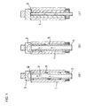
- Figures 1(a), 1(b) and 1(c) show examples of the nozzle for inner circumferential surface laminar flow cooling.
- a track bushing is loaded in an upright condition in a quenching system.
- a guide tube 2 having an outside diameter smaller than the inside diameter of a track bushing 1 is disposed at the inner circumferential surface side of the track bushing 1 and a diverting member 3 is pressed against a flat sealing portion at the upper end face of the track bushing 1.
- the underside of the diverting member 3 is constituted by a spherical surface or similar curved surface.
- a cooling medium flows upwardly from underneath (as indicated by arrow P) within the guide tube 2 and is diverted by the diverting member 3 (as indicated by arrow Q) at a position upper than the uppermost position of the track bushing 1. Thereafter, the cooling medium flows (as indicated by arrow R) within the space defined by the outer circumferential surface of the guide tube 2 and the inner circumferential surface of the track bushing 1.
- the outer circumferential surface of a guide tube 4 is treated so as to have irregularities 5, which promotes vapor film destruction at the time of quenching.
- the laminar flow cooling by the inside nozzle 6 has such a feature that a constantly cold cooling medium can be evenly supplied to the upper, middle and lower parts of the inner circumferential surface of a track bushing. It is apparent that when simultaneously quenching the outer circumferential surfaces of a plurality of overlapped bushings using, for example, intermediate partition jigs, the above laminar flow cooling is suitably utilized for increasing hardenability in the gap between adjacent track bushings and forming a quench-hardened case in the flat sealing portions at both end faces of the track bushing.
- the sprays be angled to face downward as shown in the drawing thereby forming a flow directed in a discharging direction.
- This technique is suitably applied to cooling of the inner circumferential surface of a longer cylindrical tube.
- the laminar flow generation method making use of jets from the inside nozzle 6 requires a number of nozzle holes in order to ensure a flow rate above a certain level and reveals disadvantageous properties such as poor controllability in stopping inner circumferential surface cooling in mid course. Therefore, this method should be employed in consideration of both of the cost and properties.
- the laminar flow generation method using the guide tube 2 is advantageous. For checking a laminar flow, it is preferable to put the spray nozzle in a transparent cylindrical tube and visually inspect the condition (pressure, flow rate) under which air bubbles caused by the sprays disappear.
- FIGs 2(a) and 2(b) show diverting members according to modifications. It is apparent that the configuration of the underside of the diverting member is not limited to curved faces such as shown in Figures 1(a) and 1(b), and the same effect of the curved diverting member can be achieved by a diverting member 3A having a triangular profile at its underside as shown in Figure 2(a) or a diverting member 3B having a trapezoidal profile at its underside as shown in Figure 2(b).
- Figure 3 shows the configuration and layout of a partition jig used when cooling the inner circumferential surfaces of two track bushings in an overlapped condition.
- the partition jig for dividing an inner circumferential surface cooling medium from an outer circumferential surface cooling medium comprises an upper partition jig 7, a lower partition jig 8, and an intermediate partition jig 9.
- the upper and lower partition jigs 7, 8 have, at their inner circumferential surfaces, thin cylindrical sections 7a, 8a, respectively, for preventing cooling of the inner circumferential surface and are pressed against flat sealing portions at both end faces of the track bushing 1 and against chamfered inner circumferential surface portions of the track bushing 1.
- the intermediate partition jig 9 has, at its inner circumferential surface, thin cylindrical sections 9a, 9a for preventing cooling of the inner circumferential surface.
- the adjacent track bushings 1 are overlapped with each other through the intermediate partition jig 9 in such a manner that their end faces are exposed.
- cooling of the inner circumferential surface in the vicinity of both end faces of each track bushing 1 is speeded down and both end face sections are effectively heated by additional induction heating from the outer circumferential surface so that the surface layer of the flat sealing portion of each end face can be quench-hardened to a depth no less than one-half the wall thickness of the track bushing 1 from the outer circumferential surface.
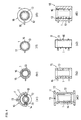
- Figures 4(a1), 4(a2) to 4(d1), 4(d2) exemplify outer-circumference cylindrical bodies for intratube flow cooling of the outer circumferential surface.
- a saddle-shaped heating inductor 11 and an outer circumferential surface cooling jacket 12 are integrally formed.
- reference numeral 13 designates an insulating material and reference numeral 14 designates ferrite iron.
- the cooling medium forming a laminar flow is supplied from a number of nozzle holes defined in the outer circumferential surface cooling jacket 12.
- the outer circumferential surface cooling jacket 12 is not necessarily integral with the saddle-shaped heating inductor 11 but may be divided into, for example, two parts. It is obviously possible to arrange these two halves so as to be located at positions where they are not induction heated by the saddle-shaped heating inductor during induction heating and to combine them to form the cylindrical tube when the induction heating is stopped to start outer circumferential surface cooling. In this case, an intricate device such as the insulating material 13 is apparently unnecessary.
- Figures 4(b1) and 4(b2) show an outer-circumference cylindrical body 15 having a spiral coil 16 inserted therein.
- Reference numeral 13 designates an insulating material.
- Figures 4(c1) and 4(c2) show an outer circumference tube 17 in which a cylindrical body is inserted in the bore of the spiral coil 16 with the insulating material 13 between.
- Figures 4(d1) and 4(d2) show an outer-circumference cylindrical body 18 in which the outer circumferential surface cooling jacket 12 is disposed at the outer circumference section of the spiral coil 16 with the insulating material 13 between.
- the cooling medium forming a laminar flow is supplied from a number of nozzle holes defined in the outer circumferential surface cooling jacket 12, like the case shown in Figures 4(a1) and 4(a2).
- outer circumferential surface cooling jacket 12 of Figures 4(d1) and 4(d2) effectively functions, when divided into parts like the above-described outer circumferential surface cooling jacket 12 composed of two halves. In this case, there is apparently no need to use an intricate device such as the insulating material 13.
- the cooling medium be introduced from either the upper end or lower end of the track bushing 1 and discharged from the opposite end. It is also possible that the cooling medium is introduced from both ends of the track bushing 1 as indicated by arrows S and T in Figure 5 and discharged from the center of the track bushing 1 as indicated by arrows U and V. Another alternative is such that the cooling medium is introduced from the center and discharged from both ends, reversely to the above case.
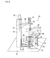
- Figure 6 is a schematic structural diagram exemplifying a quenching system.
- a column support 22 stands upright on a base 21 on which a induction heater 23 and a cooling system 24 are supported.
- a first arm member 25 is supported by an elevating means (not shown) so as to be freely lifted and lowered.
- a second arm member 28 is supported by an elevating motor 26 and a ball screw 27 so as to be freely lifted and lowered.
- the induction heater 23 comprises a high frequency transformer 29 connected to a high frequency power source (not shown) and a spiral coil 30 disposed at the outer circumferential surface of the track busing 1, being connected to the high frequency transformer 29.
- the cooling system 24 comprises the guide tube (water guide tube) 2 for use in cooling the inner circumferential surface of the track bushing 1 and the outer circumferential surface cooling jacket 12 for cooling the outer circumferential surface of the track bushing 1, whereby the inner circumferential surface cooling and the outer circumferential cooling can be independently controlled.
- a gear motor 32 for forwardly, reversely rotating the support system 31 through a driven belt is also supported on the first arm member 25.
- the lower partition jig 8 is attached to the upper end of the support system 31.
- Supported on the second arm member 28 is a pressure device 34 which is vertically moved by an air cylinder 33 and the upper partition jig 7 is attached to the lower end of the pressure device 34.
- a thermoviewer 35 for measuring the temperature of the outer circumferential surface of the track bushing 1 is disposed so as to be vertically movable by an air cylinder 36.
- the quenching operation by use of the quenching system 20 of the above structure is carried out with a track bushing material which is set in the present system after being entirely heated to a quenching temperature in a different process, or which is subjected to induction heating by use of the induction heater 23 after being set in the present system.
- the support system 31 is lifted to a specified position by elevation of the first arm member 25 and after placing the track bushing 1 on the support system 31, the second arm member 28 is lowered to a specified level by driving the elevating motor 26.
- the pressure device 34 is lowered by operation of the air cylinder 33 with the upper partition jig 7 positioned at the lower end of the pressure device 34 being pressed against the upper end face of the track bushing 1.
- the first arm member 25 and the second arm member 28 are synchronously lowered, thereby inserting the guide tube 2 into the bore of the track bushing 1 and enclosing the outer circumferential surface of the track bushing 1 with the spiral coil 30 and the outer circumferential surface cooling jacket 12. Then, a series of quenching processes is carried out in such a way that while induction heating from the outer circumferential surface being carried out, cooling from the inner circumferential surface is effected and after an elapse of a specified time, the induction heating from the outer circumferential surface is stopped and cooling is done. During the additional heating of the outer circumferential surface, the support system 31 is rotated about its axis in order to promote uniform heating.
- the rotation of the support system 31 is stopped.
- the temperature of the outer circumferential surface of the track bushing 1 is measured by the thermoviewer 35 to ensure the quenching quality of the outer circumferential surface.
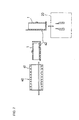
- Figure 7 is a schematic structural diagram exemplifying a thermal treatment system.
- a thermal treatment system 40 comprises a tunnel type induction heating furnace (heater) 41 for substantially uniformly heating the entire track bushing 1 to a quenching temperature; and a conveyor system 42 for carrying the track bushing 1 which has been heated by the tunnel type induction heating furnace 41 into the quenching system 20 and carrying the track bushing 1 which has undergone the quenching treatment out of the quenching system 20.
- thermal treatment system 40 enables overall heating of a plurality of track bushings 1 by use of the tunnel type induction heating furnace 41, so that improved heating productivity can be achieved.
- it provides such an advantage that degradation of the quenching jigs and others can be prevented.
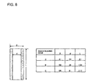
- Figure 8 shows the dimensions of three types of track bushings used in the following examples.
- the edges of these track bushings at their inner circumference side are respectively cut off to form a chamfer having a width of 1 to 1.5 cm.
- the steel material used herein is carbon steel having a carbon concentration of about 0.5 wt%.
- the DI value of the bushings A, B is 0.85 inch and the DI value of the bushing C is 1.63 inches.
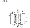
- the saddle-shaped heating inductor 11 having ferrite iron 14 embedded in the inner circumferential surface thereof as shown in Figure 9 was used as the heating inductor for induction heating.
- the outer circumferential surface cooling jacket 12 was disposed on the peripheral side of the saddle-shaped heating inductor 11 and the guide tube (water guide tube) 2 for cooling water was disposed in the bore of the heating inductor 11.
- the length of the embedded ferrite iron 14 was substantially equal to the length of the track bushing 1.
- the saddle-shaped heating inductor 11 was about 3 mm away from the outer circumferential surface of the track bushing 1.
- a high frequency heating power source of 6 kHz and 300 kW was used.
- reference numeral 13 designates an insulating material.
- the track bushing 1 was fixed at its upper and lower ends by means of the upper partition jig 7 and lower partition jig 8 for dividing the cooling medium for the inner circumferential surface of the track bushing from the cooling medium for the outer circumferential surface of the same.
- the track bushing 1 is rotated at a speed of 240 rpm while being entirely heated to about 950°C.
- the heating time, for example, for the track bushing B was about 24 seconds.
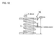
- induction heating was done, using the spiral coil 16 such as shown in Figure 12 for the track bushing B in order to prevent the electric discharge phenomenon observed in Example 1.
- the basic design of the spiral coil 16 is as follows: A copper tube of ⁇ 10 mm was wound such that the coil spacing was 10 to 25 mm, the inside diameter of the coil was about 15 mm larger than the outside diameter of the track bushing, and a 1/2 turn at each coil end was parallel with the associated end face of the track bushing.
- the same high frequency power source as in Example 1 was used to heat the track bushing B with an input power of 110 kW per bushing.
- the time required for heating the track bushing B to about 950°C was about 12 seconds.
- Example 1 the main cause of the prevention of the electric discharge phenomenon which is observed in Example 1 is that the direction of the current allowed to flow in the track bushings by the saddle-shaped heating inductor is parallel with the axis of the cylindrical track bushing, whereas the direction of the current allowed to flow in the track bushings by the spiral coil is the same as the circumferential direction of the cylindrical track bushing.
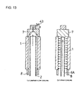
- Example 3 a flowing test by visual inspection was made in the following way: Water was used as the cooling medium for inner circumferential surface cooling and a transparent, cylindrical acrylic resin tube having the same inside diameter as that of the track bushing was used in place of the track bushing. More concretely, the outside diameter of the guide tube 2 for cooling water was varied so as to be 2, 4, 8, 10 and 20 mm smaller than the inside diameter of the track bushing (acrylic resin cylindrical tube) 1 as shown in Figure 13.
- cooling water was flowed downwardly from above the cylindrical axis of the track bushing into the space defined by the inner circumferential surface of the track bushing 1 and the outer circumferential surface of the guide tube.
- the flow rates of water employed in the test were 25, 50, 100, 150, 200 and 300 liters/min.
- a spray nozzle 6A as shown in Figure 13(b) was used.
- the nozzle for the track bushing B is designed such that the bore diameter of the nozzle is ⁇ 1.3 mm; the outside diameter of the nozzle is 15 mm which is smaller than the inside diameter of the track bushing (38 mm) by about 18 times the bore diameter of the nozzle; and nozzle holes are arranged in a zigzag pattern to cool the area of the inner circumferential surface of the track bushing having a diameter that is about 9 times the bore diameter of the nozzle.
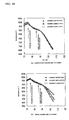
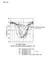
- the track bushing C was heated to about 980°C under the same condition as in Example 2 and then, allowed to cool for 10 seconds. Only the above-described laminar flow cooling and spray cooling were done with flow rates of 100 and 200 liters/min without carrying out additional heating with high frequency. While changes in the temperature of the outside circumferential surface being measured by a non-contact type photo-thermometer, the speed and uniformity of the cooling were observed. As a result, it was found that, with this laminar flow cooing method, the upper, middle and lower parts of the track bushing were all substantially uniformly cooled as seen from Figure 14(a).
- the spray cooling method was adapted, the speed of cooling the upper part was found to be nearly the same as that of the laminar flow cooling, but, cooling of the middle and lower parts was slow as seen from Figure 14(b). It can be understood from the result that the laminar cooling method is very effective as an inner circumferential surface cooling method. Note that where the flow rate was increased to 300 liters/min in the case of the spray cooling method, substantially uniform cooling could be achieved. This is because the inner circumferential surface was brought into a laminar flow cooled condition as indicated in Example 3.
- Figure 15 shows a partition jig used for the track bushing C in Example 5.
- the upper partition jig 7 and the lower partition jig 8 have 10 mm-long, thin cylindrical sections 7a, 8a respectively, which are disposed close to the inner circumferential surface of the track bushing 1, for preventing inner circumferential surface cooling.
- These thin cylindrical sections 7a, 8a are designed to be fixed in contact with the chamfers of the track bushing 1 which have an angle of about 45 degrees.
- SUS304 and asbestos were used as the material of the partition jigs.
- Example 6 a check was made in the following case: After heating by use of the saddle-shaped heating inductor of Example 1, the track bushing was allowed to cool for a specified time under the conditions shown in Table 1. Then, while carrying out additional induction heating from the outer circumferential surface under the condition similar to the heating condition, the laminar flow cooling with various flow rates and the spray cooling described in Example 3 were applied to the inner circumferential surface, using a guide tube having an outside diameter 8 mm smaller than the inside diameter of the track bushing. After completion of cooling, whether or not quenching irregularities had occurred was checked by measuring the hardnesses of the inner and outer circumferential surfaces.
- Figure 16 shows hardness distributions obtained in the following cases (I) and (II):
- the jacket for outer circumferential surface spray cooling used in Example 6 has nozzles having a bore diameter of 1.5 mm and arranged in a zigzag pattern at intervals of 13. 5 mm.
- the clearance between the outer circumferential surface of the track bushing and the inner circumferential surface of the jacket is 30 mm for the track bushings A, B and C.
- Table 2 shows the result of quenching of the inner and outer circumferential surfaces.
- Inner circumferential surface cooling was effected while sequentially directing the spray water jetted from the inside nozzle downward such that the spray water at the lower part has a downward angle of 30 degrees in maximum and as a result, the problem of quenching irregularities at the inner circumferential surface could be almost solved. However, when quenching two or more track bushings at the same time, occurrence of quenching irregularities could not be prevented.
- two track bushings B were first heated using the spiral coil of Example 2 and then allowed to cool under the conditions shown in Table 1 for a specified time. Thereafter, the inner circumferential surfaces were cooled by the laminar flow cooling or spray cooling while carrying out additional induction heating from the outer circumferential surfaces for a specified time under substantially the same condition as the heating condition. After stopping the additional induction heating, the coil was removed within one second and subsequently, outer circumferential surface cooling was effected. After such a series of quenching processes, occurrence of quenching irregularities was checked by measurement of the hardnesses of the inner and outer circumferential surfaces. The result is shown in Table 3. Table 3 also shows the result of the spray cooling of the outer circumferences through the clearances of the coil.
- Figure 18 shows the surface hardnesses of the flat sealing portions, which corresponds to Figures 17(a1), 17(a2) to 17(c1), 17(c2).
- the flat sealing portions can be quench-hardened to a depth which is equal to or more than one-half the thickness of the track bushing from the outer circumferential surface, by utilizing the cooling prevention effect of the partition jigs when preceding cooling of the inner circumferential surface is effected while carrying out additional induction heating from the outer circumferential surface.
- Example 8 the track bushing C was entirely heated under the same condition as in Example 7 and then soaking was effected by letting the track bushing C cool for 10 seconds. After additional induction heating from the outer circumferential surface and laminar flow cooling of the inner circumferential surface had been simultaneously carried out for 16 seconds, the additional heating and the inner circumferential surface cooling were interrupted for four seconds. Subsequently, cooling from the inner and outer circumferential surfaces was effected, thereby completing the quenching operation.
- air when interrupting the inner circumferential surface cooling, air was introduced by the gas introducing valve 43 described in Example 3 in order to increase the dischargeability of the laminar flow during the interruption. In another case, air was not introduced. From a comparison between these cases, it was ascertained that only in the case where the dischargeability of the laminar flow during the interruption was increased, quench irregularities did not occur at the inner circumferential surface of the track bushing C so that excellent quality could be achieved.
- Example 9 the outer circumferential surface of the track bushing B was cooled by the laminar flow cooling.
- Figure 20 shows the schematic configuration of a system for quenching inner and outer circumferential surfaces by the laminar flow cooling.
- This quenching system is designed such that an outer-circumference cylindrical body 44 having an inside diameter larger than the outside diameter of the track bushing 1 is disposed; a cooling medium is allowed to flow in an axial direction of the track bushing 1 between the outer circumferential surface of the track bushing 1 and the outer-circumference cylindrical body 44; and a spiral high frequency coil 45 is disposed so as to surround the outer-circumference cylindrical body 44.
- the outer-circumference cylindrical body 44 is made of a quartz material having a wall thickness of 5 mm.
- reference numeral 46 designates an insulating material.
- the flow rate of water at the outer circumferential surface was 300 liters/min and the flow rate of water at the inner circumferential surface was 200 liters/min.
- the hardness of the outer circumferential surface was found to be the same as in quenching with the coil being displaced as shown in Table 3 of Example 7. It can be understood from this that the laminar flow cooling of the outer circumferential surface is desirable in view of the wear resistance of the track bushing and saves the investment in the equipment for coil displacement.
- Example 10 the strength of the track bushing C which had undergone the thermal treatment of Example 7 and then tempering at 180°C for two hours and the strength of the track bushing C which had undergone only self tempering of the inner circumferential surface quench-hardened case described in Example 8 were respectively measured.
- the strength of the track bushing C prepared by carburization-quenching an SCM420 steel material and tempering it at 180°C for two hours was checked.
- the impact fatigue tester shown in Figure 21 was used in the strength evaluation. Specifically, impact loads corresponding to twice, three times and four times the weight of the vehicle (50,000 kg) were imposed on the specimens and the number of impacts given to each specimen until destruction occurred was checked. Figure 22 shows this measurement result.
- the track bushing according to the invention presented higher impact fatigue strength than the track bushing prepared by the conventional carburization treatment.
- the track bushing whose inner circumferential surface quench-hardened case was self-tempered as described in Example 8, has also been found to be excellent in strength so that significant improvements in productivity and cost reduction can be expected thanks to the obviation of the need for another low temperature tempering treatment.
Landscapes
- Chemical & Material Sciences (AREA)
- Engineering & Computer Science (AREA)
- Mechanical Engineering (AREA)
- Physics & Mathematics (AREA)
- Thermal Sciences (AREA)
- Crystallography & Structural Chemistry (AREA)
- Materials Engineering (AREA)
- Metallurgy (AREA)
- Organic Chemistry (AREA)
- Combustion & Propulsion (AREA)
- Transportation (AREA)
- Heat Treatment Of Articles (AREA)
Abstract
Description
in a series of quenching processes in which by use of a quenching system capable of carrying out induction heating from the outer circumferential surface of a track bushing and capable of independently carrying out inner circumferential surface cooling and outer circumferential surface cooling while pressing a partition jig against each end face of the track bushing such that a cooling medium for the inner circumferential surface of the track bushing and a cooling medium for the outer circumferential surface do not interfere with each other, after setting a track bushing material, which has been entirely heated to a quenching temperature by induction heating from the outer circumferential surface or by another process, in the quenching system capable of additional induction heating from the outer circumferential surface, preceding cooling of the track bushing material from the inner circumferential surface is carried out and after an elapse of a specified time, cooling from the outer circumferential surface is carried out, or alternatively, preceding cooling from the inner circumferential surface is carried out while effecting induction heating from the outer circumferential surface and after an elapse of a specified time, the induction heating from the outer circumferential surface is stopped to effect cooling,
by speeding down the cooling of the inner circumferential surface in the neighborhood of both end faces of the track bushing and/or by use of partition jigs having such a shape that both end faces can be effectively heated by the additional induction heating from the outer circumferential surface, quench-hardened cases extending from the outer and inner circumferential surfaces, respectively, to the wall center of the track bushing are formed, with an unhardened quenched layer left between the quench-hardened cases on an inner circumferential surface side and an outer circumferential surface side, such that the quench-hardened case on the outer circumferential surface side is deeper than the quench-hardened case on the inner circumferential surface side, such that the unhardened quenched layer has a structure containing one or more selected from ferrite, pearlite and bainite which precipitate in the course of cooling from the quenching temperature, and such that the surface layers of flat sealing portions at both end faces of the track bushing are respectively quench-hardened to a depth no less than one-half the wall thickness of the track bushing from the outer circumferential surface.
in a series of quenching processes in which by use of a quenching system capable of carrying out induction heating from the outer circumferential surface of a track bushing and capable of independently carrying out inner circumferential surface cooling and outer circumferential surface cooling while pressing a partition jig against each end face of the track bushing such that a cooling medium for the inner circumferential surface of the track bushing and a cooling medium for the outer circumferential surface do not interfere with each other, after setting a track bushing material, which has been entirely heated to a quenching temperature by induction heating from the outer circumferential surface or by another process, in the quenching system capable of additional induction heating from the outer circumferential surface, preceding cooling of the track bushing material from the inner circumferential surface is carried out, or cooling from the inner circumferential surface is effected while carrying out induction heating from the outer circumferential surface and after an elapse of a specified time, cooling from the outer circumferential surface is carried out, or alternatively, the induction heating from the outer circumferential surface is stopped to effect cooling,
by adding a step in which during the induction heating from the outer circumferential surface or during the time from when the induction heating is stopped until when the cooling from the outer circumferential surface is finished, the cooling from the inner circumferential surface is stopped and the inner circumferential surface is tempered within a short time by heat diffusion from the outer circumferential surface to the inner circumferential surface,
quench-hardened cases extending from the outer and inner circumferential surfaces, respectively, to the wall center of the bushing are formed, with an unhardened quenched layer left between the quench-hardened cases on an inner circumferential surface side and an outer circumferential surface side, such that the quench-hardened case on the outer circumferential surface side is deeper than the quench-hardened case on the inner circumferential surface side, such that the unhardened quenched layer has a structure containing one or more selected from ferrite, pearlite and bainite which precipitate in the course of cooling from the quenching temperature, and such that the inner circumferential surface quench-hardened case has a tempered martensitic structure.
in a series of quenching processes in which by use of a quenching system capable of cooling the inner circumferential surface and outer circumferential surface of a track bushing material and/or carrying out induction heating from the outer circumferential surface, after the track bushing material has been heated to a quenching temperature, preceding cooling of the inner circumferential surface of the track bushing material is effected, or alternatively, preceding cooling of the inner circumferential surface is effected while carrying out additional induction heating from the outer circumferential surface, and after an elapse of a specified time, cooling from the outer circumferential surface is carried out, or alternatively, the induction heating from the outer circumferential surface is stopped to cool the outer circumferential surface,
at least the inner circumferential surface of the track bushing is cooled by a cooling medium flowing in parallel with the inner circumferential surface and axial direction of the track bushing, so that a quench-hardened case can be formed without irregularities in the inner circumferential surface of a long track bushing having a small inside diameter or in the inner circumferential surfaces of a plurality of track bushings while forming a quench-hardened case in the outer circumferential surface by the cooling from the outer circumferential surface, such that an unhardened quenched layer is left between the quench-hardened cases on inner and outer circumferential surface sides, such that the quench-hardened case on the outer circumferential surface side is deeper than the quench-hardened case on the inner circumferential surface side, and such that the unhardened quenched layer has a structure containing one or more selected from ferrite, pearlite and bainite which precipitate in the course of cooling from the quenching temperature.
wherein, in the method having the third aspect, the cooling of the outer circumferential surface is carried out by the laminar flow cooling in such a way that the track bushing is inserted into an outer-circumference cylindrical body having an inside diameter larger than the outside diameter of the track bushing and the cooling medium is allowed to flow in parallel with the outer circumferential surface of the track bushing in the axial direction of the track bushing between the outer-circumference cylindrical body and the outer circumferential surface of the track bushing. Herein, part of the outer-circumference cylindrical body may include a saddle-shaped heating inductor or a spiral coil. Alternatively, the outer-circumference cylindrical body may be disposed inside or outside a saddle-shaped heating inductor or a spiral coil. The outer-circumference cylindrical body may be made from an insulating material so as to be hardly subjected to induction heating. From the view point of the fact that the outer-circumference cylindrical body should not be subjected to induction heating, the following mechanisms are suitably employed. Specifically, the outer-circumference cylindrical body is not located in the neighborhood of the coil during the induction heating and there is provided a mechanism for immediately shifting the outer-circumference cylindrical body to the position where it functions during the outer circumferential surface cooling. Alternatively, the outer-circumference cylindrical body is constituted by two or more parts and there is provided a mechanism for assembling the outer-circumference cylindrical body from these parts during the outer circumferential surface cooling. The outer-circumference cylindrical body is preferably made from an inexpensive metal having good durability.
by a series of quenching processes in which after the material of a track bushing has been entirely heated to a quenching temperature, preceding cooling from the inner circumferential surface of the track bushing material is carried out, or preceding cooling from the inner circumferential surface is effected while carrying out induction heating from the outer circumferential surface of the track bushing material and after an elapse of a specified time, cooling from the outer circumferential surface is carried out,
quench-hardened cases extending from the outer and inner circumferential surfaces, respectively, to the wall center of the track bushing are formed, with an unhardened quenched layer left between the quench-hardened cases on an inner circumferential surface side and an outer circumferential surface side, such that the quench-hardened case on the outer circumferential surface side is deeper than the quench-hardened case on the inner circumferential surface side, such that the unhardened quenched layer has a structure containing one or more selected from ferrite, pearlite and bainite which precipitate in the course of cooling from the quenching temperature and such that the surface layers of flat sealing portions at both end faces of the track bushing are respectively quench-hardened to a depth no less than one-half the wall thickness of the track bushing from the outer circumferential surface.
by a series of quenching processes in which after the material of a track bushing has been entirely heated to a quenching temperature, preceding cooling from the inner circumferential surface of the track bushing material is effected while carrying out induction heating from the outer circumferential surface of the track bushing material and after an elapse of a specified time, cooling from the outer circumferential surface is carried out, the series of quenching processes further including a step in which during the induction heating from the outer circumferential surface or during the time from when the induction heating is stopped until when the cooling from the outer circumferential surface is finished, the cooling from the inner circumferential surface is stopped to temper the inner circumferential surface within a short time by heat diffusion from the outer circumferential surface to the inner circumferential surface,
quench-hardened cases extending from the outer and inner circumferential surfaces, respectively, to the wall center of the track bushing are formed, with an unhardened quenched layer left between the quench-hardened cases on an inner circumferential surface side and an outer circumferential surface side, such that the quench-hardened case on the outer circumferential surface side is deeper than the quench-hardened case on the inner circumferential surface side, such that the unhardened quenched layer has a structure containing one or more selected from ferrite, pearlite and bainite which precipitate in the course of cooling from the quenching temperature, and such that the quench-hardened case on the inner circumferential surface side has a tempered martensitic structure.
wherein the quenching system has an inner circumferential surface cooling system including a tubular or cylindrical body which has an outside diameter smaller than the inside diameter of the track bushing and which is disposed on the side of the inner circumferential surface of the track bushing, and the inner circumferential surface cooling system allows a cooling medium to flow within a space defined by the inner circumferential surface of the track bushing and the outer circumferential surface of the tubular or cylindrical body to cool the inner circumferential surface by a laminar flow.
the plurality of track bushings can be formed such that each track bushing has a structure having a U-shaped smooth hardness distribution wherein quench-hardened cases extending from the outer and inner circumferential surfaces, respectively, to the wall center of the track bushing are formed, with an unhardened quenched layer left between the quench-hardened cases on an inner circumferential surface side and an outer circumferential surface side, such that the quench-hardened case on the outer circumferential surface side is deeper than the quench-hardened case on the inner circumferential surface side, and such that the unhardened quenched layer has a structure containing one or more selected from ferrite, pearlite, bainite and martensite which precipitate in the course of cooling from the quenching temperature.
wherein the quenching system comprises an outer-circumference cylindrical tube for introducing a cooling medium, the outer-circumference cylindrical tube being disposed at the side of the outer circumferential surface of the track bushing and having an outside diameter larger than that of the track bushing, and
wherein the cooling medium is allowed to flow between the outer-circumference cylindrical tube and the outer circumferential surface of the track bushing to cool the outer circumferential surface by a laminar flow.
| QUENCHING CONDITIONS | ||
| TRACK BUSHING CODE | STANDING TO COOL/SOAKING TIME (sec) | ADDITIONAL HEATING AND PRECEDING INNER CIRCUMFERENTIAL SURFACE COOLING TIME (sec) |
| A | 1 | 2 |
| | 2 | 5 |
| | 10 | 20 |

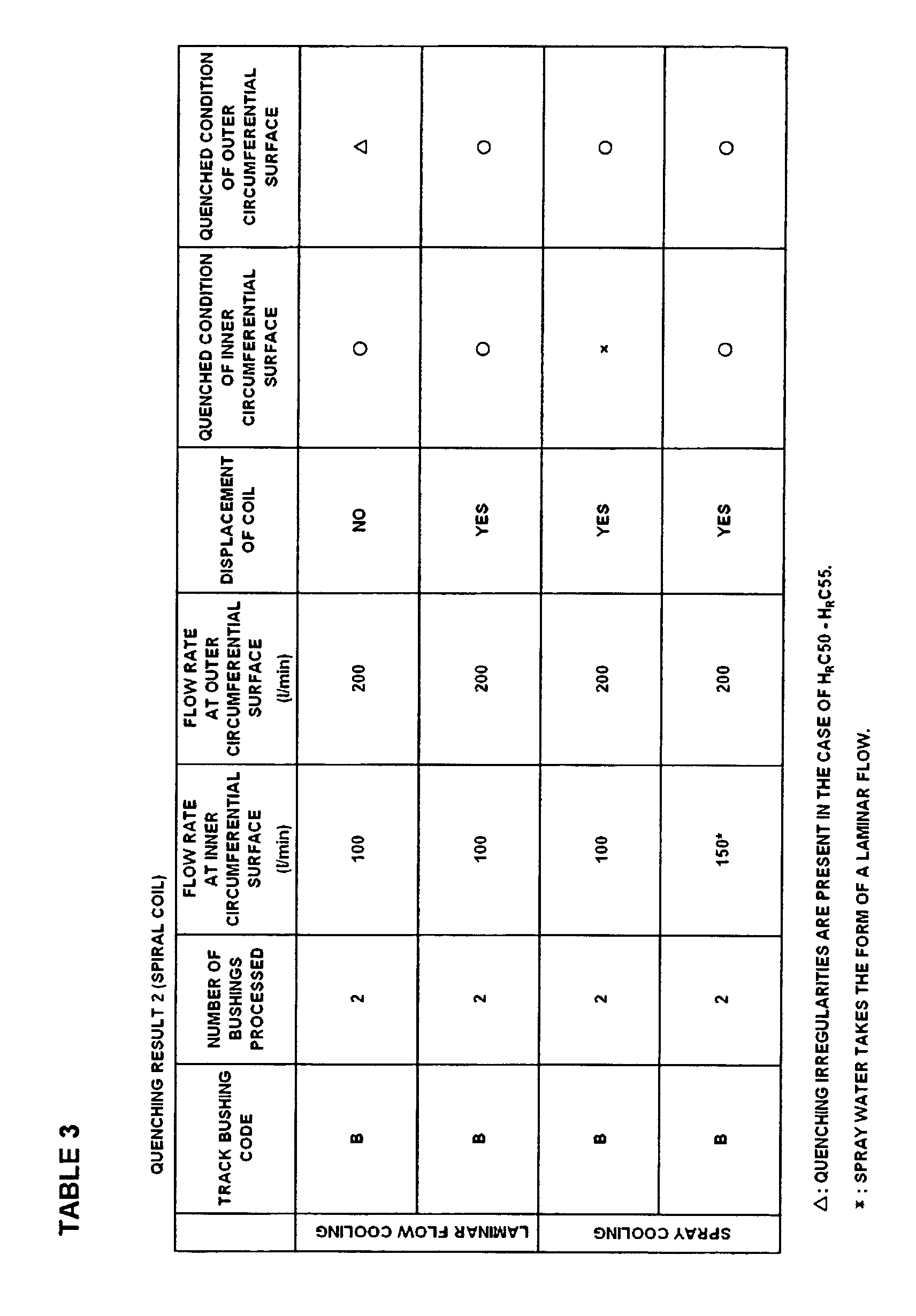
Claims (39)
- A method of producing a track bushing wherein,
in a series of quenching processes in which by use of a quenching system capable of carrying out induction heating from the outer circumferential surface of a track bushing and capable of independently carrying out inner circumferential surface cooling and outer circumferential surface cooling while pressing a partition jig against each end face of the track bushing such that a cooling medium for the inner circumferential surface of the track bushing and a cooling medium for the outer circumferential surface do not interfere with each other, after setting a track bushing material, which has been entirely heated to a quenching temperature by induction heating from the outer circumferential surface or by another process, in the quenching system capable of additional induction heating from the outer circumferential surface, preceding cooling of the track bushing material from the inner circumferential surface is carried out and after an elapse of a specified time, cooling from the outer circumferential surface is carried out, or alternatively, preceding cooling from the inner circumferential surface is carried out while effecting induction heating from the outer circumferential surface and after an elapse of a specified time, the induction heating from the outer circumferential surface is stopped to effect cooling,
by speeding down the cooling of the inner circumferential surface in the neighborhood of both end faces of the track bushing and/or by use of partition jigs having such a shape that both end faces can be effectively heated by the additional induction heating from the outer circumferential surface, quench-hardened cases extending from the outer and inner circumferential surfaces, respectively, to the wall center of the track bushing are formed, with an unhardened quenched layer left between the quench-hardened cases on an inner circumferential surface side and an outer circumferential surface side, such that the quench-hardened case on the outer circumferential surface side is deeper than the quench-hardened case on the inner circumferential surface side, and such that the unhardened quenched layer has a structure containing one or more selected from ferrite, pearlite and bainite which precipitate in the course of cooling from the quenching temperature, and such that the surface layers of flat sealing portions at both end faces of the track bushing are respectively quench-hardened to a depth no less than one-half the wall thickness of the track bushing from the outer circumferential surface. - A method of producing a track bushing wherein,
in a series of quenching processes in which by use of a quenching system capable of carrying out induction heating from the outer circumferential surface of a track bushing and capable of independently carrying out inner circumferential surface cooling and outer circumferential surface cooling while pressing a partition jig against each end face of the track bushing such that a cooling medium for the inner circumferential surface of the track bushing and a cooling medium for the outer circumferential surface do not interfere with each other, after setting a track bushing material, which has been entirely heated to a quenching temperature by induction heating from the outer circumferential surface or by another process, in the quenching system capable of additional induction heating from the outer circumferential surface, preceding cooling of the track bushing material from the inner circumferential surface is carried out, or cooling from the inner circumferential surface is effected while carrying out induction heating from the outer circumferential surface and after an elapse of a specified time, cooling from the outer circumferential surface is carried out, or alternatively, the induction heating from the outer circumferential surface is stopped to effect cooling,
by adding a step in which during the induction heating from the outer circumferential surface or during the time from when the induction heating is stopped until when the cooling from the outer circumferential surface is finished, the cooling from the inner circumferential surface is stopped and the inner circumferential surface is tempered within a short time by heat diffusion from the outer circumferential surface to the inner circumferential surface,
quench-hardened cases extending from the outer and inner circumferential surfaces, respectively, to the wall center of the track bushing are formed, with an unhardened quenched layer left between the quench-hardened cases on an inner circumferential surface side and an outer circumferential surface side, such that the quench-hardened case on the outer circumferential surface side is deeper than the quench-hardened case on the inner circumferential surface side, such that the unhardened quenched layer has a structure containing one or more selected from ferrite, pearlite and bainite which precipitate in the course of cooling from the quenching temperature, and such that the inner circumferential surface quench-hardened case has a tempered martensitic structure. - The method of producing a track bushing according to claim 2, wherein the cooling from the inner circumferential surface is stopped during the induction heating from the outer circumferential surface or during the time from when the induction heating is stopped until when the cooling of the outer circumferential surface starts, and after the cooling from the inner circumferential surface is stopped and the tempering of the inner circumferential surface is done within a short time by heat diffusion from the outer circumferential surface to the inner circumferential surface, re-cooling of the inner circumferential surface is effected.
- The method of producing a track bushing according to claim 2 or 3, wherein the outer circumferential surface is tempered within a short time by induction heating.
- The method of producing a track bushing according to any one of claims 1 to 4, wherein the jigs for dividing the inner circumferential surface cooling medium from the outer circumferential surface cooling medium are respectively pressed against the flat sealing portions and/or chamfered inner circumferential surface portions at both end faces of the track bushing so that leakage of the mediums at their contact portions is minimized.
- A method of producing a track bushing wherein
in a series of quenching processes in which by use of a quenching system capable of cooling the inner circumferential surface and outer circumferential surface of a track bushing material and/or carrying out induction heating from the outer circumferential surface, after the track bushing material has been heated to a quenching temperature, preceding cooling of the inner circumferential surface of the track bushing material is effected, or alternatively, preceding cooling of the inner circumferential surface is effected while carrying out additional induction heating from the outer circumferential surface, and after an elapse of a specified time, cooling from the outer circumferential surface is carried out, or alternatively, the induction heating from the outer circumferential surface is stopped to cool the outer circumferential surface,
at least the inner circumferential surface of the track bushing is cooled by a cooling medium flowing in parallel with the inner circumferential surface and axial direction of the track bushing, so that a quench-hardened case can be formed without irregularities in the inner circumferential surface of a long track bushing having a small inside diameter or in the inner circumferential surfaces of a plurality of track bushings while forming a quench-hardened case in the outer circumferential surface by the cooling from the outer circumferential surface, such that an unhardened quenched layer is left between the quench-hardened cases on inner and outer circumferential surface sides, such that the quench-hardened case on the outer circumferential surface side is deeper than the quench-hardened case on the inner circumferential surface side; and such that the unhardened quenched layer has a structure containing one or more selected from ferrite, pearlite and bainite which precipitate in the course of cooling from the quenching temperature. - The method of producing a track bushing according to any one of claims 1 to 6, wherein at least either the inner circumferential surface or the outer circumferential surface is cooled by a cooling medium flowing in parallel with the axial direction of the track bushing.
- The method of producing a track bushing according to any one of claims 1 to 7, wherein the induction heating or the additional induction heating is carried out with a spiral coil and the plurality of track bushings are quenched at the same time.
- The method of producing a track bushing according to any one of claims 1 to 7, wherein the induction heating or the additional induction heating are carried out with a saddle-shaped heating inductor and the heating by the saddle-shaped heating inductor is carried out with an insulator interposed between every adjacent track bushings.
- The method of producing a track bushing according to claim 8 or 9, wherein when simultaneously quenching the plurality of track bushings, every adjacent track bushings are overlapped with each other through an intermediate partition jig such that their end faces are exposed, whereby the surface layers of the flat sealing portions of both end faces of the track bushings in contact with the intermediate partition jig are quench-hardened to a depth no less than one-half the wall thickness of the track bushings from the outer circumferential surfaces.
- The method of producing a track bushing according to any one of claims 7 to 10, wherein in order to introduce the cooling medium for cooling the inner circumferential surface, a guide tube having a smaller outside diameter than the inside diameter of the track bushing is disposed on the inner circumferential surface side and the cooling medium introduced by the guide tube is allowed to flow in parallel with the inner circumferential surface of the track bushing and in substantially parallel with the axial direction of the track bushing within a space defined by the outer circumferential surface of the guide tube and the inner circumferential surface of the track bushing, whereby laminar flow cooling is carried out.
- The method of producing a track bushing according to claim 11, wherein after introduced into the guide tube, the cooling medium for cooling the inner circumferential surface is diverted by a wall face into the space defined by the outer circumferential surface of the guide tube and the inner circumferential surface of the track bushing.
- The method of producing a track bushing according to any one of claims 7 to 12, wherein the cooling of the outer circumferential surface is carried out by the laminar flow cooling in such a way that the track bushing is inserted into an outer-circumference cylindrical body having an inside diameter larger than the outside diameter of the track bushing and the cooling medium is allowed to flow in parallel with the outer circumferential surface of the track bushing in the axial direction of the track bushing between the outer-circumference cylindrical body and the outer circumferential surface of the track bushing.
- The method of producing a track bushing according to claim 13, wherein the outer-circumference cylindrical body partially includes a saddle-shaped heating inductor or a spiral coil, or alternatively is disposed inside or outside a saddle-shaped heating inductor or a spiral coil, and wherein the outer-circumference cylindrical body is made from an insulating material so as to be hardly induction heated.
- The method of producing a track bushing according to any one of claims 7 to 14, wherein the laminar flow cooling of the inner circumferential surface and the outer circumferential surface is carried out under a cooling condition which satisfies at least one of the requirements consisting of (i) the amount of the cooling medium is 9 liters/min· cm2 or more for the sectional area obtained from the track bushing and the outside diameter of the guide tube for the cooling medium; and (ii) the flow speed of the cooling medium is 1.5 m/sec or more; and/or (iii) the amount of the cooling medium is 0.1 liter/min· cm2 for the respective areas of the inner circumferential surface and outer circumferential surface of the track bushing.
- The method of producing a track bushing according to any one of claims 6 to 14, wherein the track bushing rotates about its central axis during the induction heating.
- The method of producing a track bushing according to any one of claims 1 to 16, wherein the cooling medium for use in the cooling is water or an aqueous quenching liquid.
- The method of producing a track bushing according to any one of claims 1 to 17, wherein low temperature tempering is applied at 100°C to 350°C after the quenching treatment.
- A track bushing which is formed such that
by a series of quenching processes in which after the material of a track bushing has been entirely heated to a quenching temperature, preceding cooling from the inner circumferential surface of the track bushing material is carried out, or preceding cooling from the inner circumferential surface is effected while carrying out induction heating from the outer circumferential surface of the track bushing material and after an elapse of a specified time, cooling from the outer circumferential surface is carried out,
quench-hardened cases extending from the outer and inner circumferential surfaces, respectively, to the wall center of the bushing are formed, with an unhardened quenched layer left between the quench-hardened cases on an inner circumferential surface side and an outer circumferential surface side, such that the quench-hardened case on the outer circumferential surface side is deeper than the quench-hardened case on the inner circumferential surface side and such that the unhardened quenched layer has a structure containing one or more selected from ferrite, pearlite and bainite which precipitate in the course of cooling from the quenching temperature and such that the surface layers of flat sealing portions at both end faces of the track bushing are respectively quench-hardened to a depth no less than one-half the wall thickness of the track bushing from the outer circumferential surface. - The track bushing according to claim 19, wherein the surfaces of the flat sealing portions at both end faces are substantially entirely quench-hardened, with the unhardened quenched layer formed so as to extend from the wall center toward the inner circumferential surface side, the unhardened quenched layer being connected to the inner circumferential surface in the neighborhood of both end faces except the flat sealing portions at both end faces.
- The track bushing according to claim 19 or 20, wherein the quench-hardened cases are treated by low-temperature tempering so that the hardness of at least the quench-hardened cases in the outer circumferential surface and in the flat sealing portions is equal to or more than Hv = 500.
- A track bushing which is formed such that
by a series of quenching processes in which after the material of a track bushing has been entirely heated to a quenching temperature, preceding cooling from the inner circumferential surface of the track bushing material is effected while carrying out induction heating from the outer circumferential surface of the track bushing material and after an elapse of a specified time, cooling from the outer circumferential surface is carried out, the series of quenching processes further including a step in which during the induction heating from the outer circumferential surface or during the time from when the induction heating is stopped until when the cooling from the outer circumferential surface is finished, the cooling from the inner circumferential surface is stopped to temper the inner circumferential surface within a short time by heat diffusion from the outer circumferential surface to the inner circumferential surface,
quench-hardened cases extending from the outer and inner circumferential surfaces, respectively, to the wall center of the track bushing are formed, with an unhardened quenched layer left between the quench-hardened cases on an inner circumferential surface side and an outer circumferential surface side, such that the quench-hardened case on the outer circumferential surface side is deeper than the quench-hardened case on the inner circumferential surface side, such that the unhardened quenched layer has a structure containing one or more selected from ferrite, pearlite and bainite which precipitate in the course of cooling from the quenching temperature, and such that the quench-hardened case on the inner circumferential surface side has a tempered martensitic structure. - The track bushing according to claim 22, wherein the cooling from the inner circumferential surface is stopped during the induction heating from the outer circumferential surface or during the time from when the induction heating is stopped until when the cooling from the outer circumferential surface starts, and after the cooling from the inner circumferential surface has been stopped and the inner circumferential surface has been tempered for a short time by heat diffusion from the outer circumferential surface to the inner circumferential surface, the inner circumferential surface is cooled again.
- The track bushing according to claim 22 or 23, wherein the surface layers of the flat sealing portions at both end faces are respectively quench-hardened to a depth no less than one-half the wall thickness of the track bushing from the outer circumferential surface.
- The track bushing according to any one of claims 22 to 24, wherein tempering treatment by induction heating is applied to the quench-hardened case on the outer circumferential surface side for a short time so that at least the hardness of the outer circumferential surface is Hv = 500 or more.
- A track bushing producing apparatus having a heater for entirely heating the material of a track bushing to a quenching temperature and/or a quenching system capable of induction heating the track bushing material from its outer circumferential surface,
wherein the quenching system has an inner circumferential surface cooling system including a tubular or cylindrical body which has an outside diameter smaller than the inside diameter of the track bushing and which is disposed on the side of the inner circumferential surface of the track bushing, and the inner circumferential surface cooling system is designed to allow a cooling medium to flow within a space defined by the inner circumferential surface of the track bushing and the outer circumferential surface of the tubular or cylindrical body to cool the inner circumferential surface by a laminar flow. - The track bushing producing apparatus according to claim 26, wherein the inner circumferential surface cooling system comprises a gas introducing valve for discharging the cooling medium outwardly from the track bushing while the inner circumferential surface cooling being suspended, the cooing medium flowing within the space defined by the guide tube and the inner circumferential surface of the track bushing.
- The track bushing producing apparatus according to claim 26 or 27 wherein the guide tube for introducing the cooling medium is formed from ceramics materials such as Si3N4, Al2O3 and SiO2 which hardly generate heat in induction heating or antiferromagnetic alloys such as Fe - 30 to 50 at% Mn alloys.
- A track bushing producing apparatus comprising a heater for entirely and substantially uniformly heating the material of a track bushing to a quenching temperature and a quenching system capable of carrying out additional induction heating of the track bushing material from its outer circumferential surface,
wherein the quenching system comprises an outer-circumference cylindrical tube for introducing a cooling medium, the outer-circumference cylindrical tube being disposed at the side of the outer circumferential surface of the track bushing and having an outside diameter larger than that of the track bushing, and
wherein the cooling medium is allowed to flow between the outer-circumference cylindrical tube and the outer circumferential surface of the track bushing to cool the outer circumferential surface by a laminar flow. - The track bushing producing apparatus according to claim 29, wherein the outer-circumference cylindrical tube for introducing the cooling medium is formed from Si3N4, Al2O3, SiO2, mullite or the like which hardly generate heat in additional induction heating.
- The track bushing producing apparatus according to claim 29, wherein the outer-circumference cylindrical body partially includes a saddle-shaped heating inductor or spiral coil, or alternatively, the outer-circumference cylindrical body is disposed inside or outside a saddle-shaped heating inductor or spiral coil and made from an insulating material so as to be hardly induction heated.
- The track bushing producing apparatus according to claim 29, wherein the outer-circumference cylindrical body, which partially includes a saddle-shaped heating inductor or is disposed outside a saddle-shaped heating inductor or spiral coil, is constituted by two or more parts which are away from the saddle-shaped heating inductor or spiral coil during the induction heating such that they are prevented from being induction heated as much as possible and are combined to form the outer-circumference cylindrical body during the cooling.
- The track bushing producing apparatus according to claim 26 or 29, wherein the quenching system is designed such that an insulating material surrounding the track bushing is provided at at least the bore side or periphery side of a coil for additional induction heating, and/or such that the outer circumferential surface of a guide tube for introducing the cooling medium for the inner circumferential surface is coated with an insulating material.
- The track bushing producing apparatus according to claim 26 or 29, wherein the quenching system includes a detector for monitoring and controlling the temperature of the outer circumferential surface of the track bushing at a start of outer circumferential surface cooling.
- A track bushing producing apparatus comprising:a supporting device for supporting a track bushing such that a specified quenching process can be effected after the material of the track bushing has been induction heated to a quenching temperature from its outer circumferential surface, or such that a specified quenching process can be effected after setting the track bushing material which has been entirely heated to a quenching temperature in a different process;a induction heater for carrying out induction heating of the track bushing supported by the supporting device, from its outer circumferential surface;a pressure device for pressurizing and fixing the track bushing by pressing partition jigs against both end faces of the track bushing such that a cooling medium for the inner circumferential surface of the track bushing and a cooling medium for the outer circumferential surface of the track bushing do not interfere with each other; anda cooling system for independently carrying out inner circumferential surface cooling and outer circumferential surface cooling.
- The track bushing producing apparatus according to claim 35, wherein the specified quenching operation is a series of quenching processes in which preceding cooling from the inner circumferential surface of the track bushing is effected or induction heating from the outer circumferential surface of the track bushing is effected while carrying out preceding cooling from the inner circumferential surface and after an elapse of a specified time, cooling from the outer circumferential surface is carried out, or alternatively, the specified quenching operation is a series of quenching processes in which cooling from the inner circumferential surface is once stopped to temper the inner circumferential surface within a short time by heat diffusion from the outer circumferential surface to the inner circumferential surface before starting cooling from the outer circumferential surface, and then, re-cooling of the inner circumferential surface and cooling from the outer circumferential surface are sequentially effected.
- The track bushing producing apparatus according to claim 35 or 36, wherein the induction heater is a spiral coil for preventing an electric discharge phenomenon at the contact parts of adjacent track bushings or at the position of each partition jig disposed between adjacent track bushings, in cases where a plurality of track bushings are heated at the same time.
- The track bushing producing apparatus according to any one of claims 35 to 37, wherein the supporting device is designed to be rotatable and vertically movable.
- A track bushing producing apparatus comprising:wherein the quenching system is designed such that while preceding cooling from the inner circumferential surface of the track bushing material is carried out, heating from the outer circumferential surface is stopped after an elapse of a specified time to cool the outer circumferential surface.a heater for substantially uniformly and entirely heating the material of a track bushing to a quenching temperature;a quenching system capable of induction heating the track bushing material from its outer circumferential surface; anda conveyor for carrying the track bushing material into the quenching system after the track bushing material has been heated by the heater and carrying the track bushing out of the quenching system after a treatment has been applied to the track bushing by the quenching system,
Applications Claiming Priority (1)
| Application Number | Priority Date | Filing Date | Title |
|---|---|---|---|
| PCT/JP2001/004827 WO2002101098A1 (en) | 2000-03-01 | 2001-06-07 | Crawler bushing and method and device for producing the same |
Publications (3)
| Publication Number | Publication Date |
|---|---|
| EP1400603A1 true EP1400603A1 (en) | 2004-03-24 |
| EP1400603A4 EP1400603A4 (en) | 2005-12-14 |
| EP1400603B1 EP1400603B1 (en) | 2009-03-18 |
Family
ID=31900078
Family Applications (1)
| Application Number | Title | Priority Date | Filing Date |
|---|---|---|---|
| EP01938559A Expired - Lifetime EP1400603B1 (en) | 2001-06-07 | 2001-06-07 | Crawler bushing and method and device for producing the same |
Country Status (7)
| Country | Link |
|---|---|
| US (3) | US20060144481A1 (en) |
| EP (1) | EP1400603B1 (en) |
| KR (1) | KR100747045B1 (en) |
| CN (1) | CN100460528C (en) |
| BR (1) | BR0117044B1 (en) |
| DE (1) | DE60138049D1 (en) |
| WO (1) | WO2002101098A1 (en) |
Cited By (4)
| Publication number | Priority date | Publication date | Assignee | Title |
|---|---|---|---|---|
| WO2007103145A1 (en) * | 2006-03-01 | 2007-09-13 | The Timken Company | Low frequency heating device and article made therefrom |
| WO2012050552A1 (en) * | 2010-10-11 | 2012-04-19 | The Timken Company | Apparatus for induction hardening |
| US8993942B2 (en) | 2010-10-11 | 2015-03-31 | The Timken Company | Apparatus for induction hardening |
| US9169529B2 (en) | 2008-04-11 | 2015-10-27 | The Timken Company | Inductive heating for hardening of gear teeth and components alike |
Families Citing this family (19)
| Publication number | Priority date | Publication date | Assignee | Title |
|---|---|---|---|---|
| KR100935112B1 (en) * | 2008-08-12 | 2010-01-08 | 주식회사 평산 | Rapid water cooling apparatus for heat treatment |
| JP5205203B2 (en) * | 2008-10-08 | 2013-06-05 | 三菱重工業株式会社 | Slag melting burner equipment |
| CA2744630C (en) | 2010-06-30 | 2018-10-09 | Camoplast Solideal Inc. | Wheel of a track assembly of a tracked vehicle |
| US8985250B1 (en) | 2010-12-14 | 2015-03-24 | Camoplast Solideal Inc. | Track drive mode management system and methods |
| KR101502019B1 (en) * | 2011-07-13 | 2015-03-12 | 토피 고교 가부시키가이샤 | Heat processing system and heat processing method |
| RU2464326C1 (en) * | 2011-07-19 | 2012-10-20 | ОАО "Первоуральский новотрубный завод" | Heat treatment method of cold deformed pipes |
| CN103146901B (en) * | 2013-03-27 | 2015-11-18 | 湖北新冶钢有限公司 | Steel pipe water quenching method |
| US11167810B2 (en) * | 2015-03-04 | 2021-11-09 | Camso Inc. | Track system for traction of a vehicle |
| WO2017000068A1 (en) | 2015-06-29 | 2017-01-05 | Camso Inc. | Systems and methods for monitoring a track system for traction of a vehicle |
| CN106636570A (en) * | 2016-12-14 | 2017-05-10 | 山推工程机械股份有限公司 | Heat treatment method for repairing of carburization pin bush |
| JP6730920B2 (en) * | 2016-12-28 | 2020-07-29 | 株式会社小松製作所 | Crawler belt bearing bush and method of manufacturing the same |
| CA3085012A1 (en) | 2017-12-08 | 2018-12-07 | Camso Inc. | Systems and methods for monitoring off-road vehicles |
| WO2020041897A1 (en) | 2018-08-30 | 2020-03-05 | Camso Inc. | Systems and methods for monitoring tracked vehicles |
| WO2020041899A1 (en) | 2018-08-30 | 2020-03-05 | Camso Inc. | Systems and methods for monitoring vehicles with tires |
| CN109604977A (en) * | 2019-02-21 | 2019-04-12 | 孙永宁 | A kind of manufacturing process of crawler belt guide |
| RU2732818C1 (en) * | 2020-03-11 | 2020-09-22 | Акционерное общество "Первоуральский новотрубный завод" (АО "ПНТЗ") | Method for production of seamless cold-deformed high-strength pipes from alloy uns n06625 |
| CN111485081B (en) * | 2020-05-26 | 2022-03-22 | 苏州辽鞍机械有限公司 | Quenching heat treatment method for pin bush |
| CN114657341B (en) * | 2022-04-14 | 2023-06-20 | 西华大学 | A hydrogen energy hybrid commercial vehicle engine crankshaft quenching equipment and method |
| CN115126790B (en) * | 2022-08-31 | 2022-11-18 | 万向钱潮股份公司 | Bearing assembly and universal joint bearing device |
Family Cites Families (37)
| Publication number | Priority date | Publication date | Assignee | Title |
|---|---|---|---|---|
| US2295272A (en) * | 1940-05-17 | 1942-09-08 | Budd Induction Heating Inc | Heat treating |
| US3227586A (en) * | 1963-08-19 | 1966-01-04 | Caterpillar Tractor Co | Track pin bushing |
| US3567529A (en) * | 1969-03-03 | 1971-03-02 | Caterpillar Tractor Co | Differentially treated track bushing |
| US3997375A (en) | 1973-07-16 | 1976-12-14 | The Algoma Steel Corporation, Limited | Steel hardening method |
| US4115675A (en) * | 1975-08-11 | 1978-09-19 | Nippon Steel Corporation | Induction heating method of steel pipe |
| US4308037A (en) | 1975-08-11 | 1981-12-29 | Institute Of Gas Technology | High temperature pollutant removal from gas streams |
| JPS554279Y2 (en) | 1975-09-02 | 1980-01-31 | ||
| US4376528A (en) | 1980-11-14 | 1983-03-15 | Kawasaki Steel Corporation | Steel pipe hardening apparatus |
| JPS5831031A (en) * | 1981-08-17 | 1983-02-23 | Nippon Steel Corp | Production of steel pipe having high strength and toughness |
| US4490187A (en) * | 1982-02-16 | 1984-12-25 | Kruppert Enterprises, Inc. | Method for heat treating steel |
| CA1227110A (en) | 1982-03-15 | 1987-09-22 | Algoma Steel Corporation Limited (The) | Pipe quenching apparatus and method |
| JPS58189327A (en) | 1982-04-30 | 1983-11-05 | Komatsu Ltd | Production of track bushing |
| US4444604A (en) | 1983-03-07 | 1984-04-24 | United States Steel Corporation | Method of preventing distortion of a heated workpiece during cooling |
| JPS6137924A (en) | 1984-07-30 | 1986-02-22 | Hitachi Ltd | Uniform cooling method of tubular body |
| US4596282A (en) | 1985-05-09 | 1986-06-24 | Xaloy, Inc. | Heat treated high strength bimetallic cylinder |
| JPH0833791B2 (en) | 1986-07-08 | 1996-03-29 | 株式会社高見沢サイバネティックス | Uninterruptible power supply interface device |
| US4820358A (en) | 1987-04-01 | 1989-04-11 | General Electric Company | Method of making high strength superalloy components with graded properties |
| JPS6442528A (en) | 1987-08-11 | 1989-02-14 | Sumitomo Metal Ind | Heat treating method for high cr ferritic welded steel pipe |
| EP0339152B1 (en) * | 1988-04-28 | 1993-08-11 | Topy Industries, Limited | Heat treatment process for bushing used in track of endless track tractor |
| JPH03120317A (en) * | 1989-10-03 | 1991-05-22 | Fuji Denshi Kogyo Kk | High-frequency quenching method |
| JPH03166320A (en) | 1989-11-22 | 1991-07-18 | Komatsu Ltd | Track bushing and its production |
| US5140118A (en) | 1991-02-19 | 1992-08-18 | Westinghouse Electric Corp. | Metal tube induction annealing method and apparatus |
| JP3069969B2 (en) * | 1991-05-10 | 2000-07-24 | 大成建設株式会社 | Composite wall and beam floor structure |
| US5249888A (en) * | 1991-12-20 | 1993-10-05 | Hughes Aircraft Company | Enhanced gradient soil and groundwater remediation method |
| US5249868A (en) | 1993-01-27 | 1993-10-05 | Caterpillar Inc. | Track bushing |
| US5702667A (en) | 1996-08-16 | 1997-12-30 | Caterpillar Inc. | Method and apparatus for heat treating a bushing |
| IT1288690B1 (en) * | 1996-11-14 | 1998-09-23 | Bruno Girardello | PROCEDURE FOR THE HEAT TREATMENT OF BUSHINGS ESPECIALLY FOR TRACKED AND SIMILAR VEHICLES |
| JPH10204534A (en) | 1997-01-21 | 1998-08-04 | Komatsu Ltd | Crawler track bush and method of manufacturing the same |
| US6270595B1 (en) * | 1997-08-25 | 2001-08-07 | Komatsu Ltd. | Bushing for crawler belt and method of manufacture |
| JP3897434B2 (en) * | 1998-02-25 | 2007-03-22 | 株式会社小松製作所 | Crawler belt bushing and manufacturing method thereof |
| US20010050121A1 (en) * | 1997-08-25 | 2001-12-13 | Komatsu Ltd. | Bushing for crawler belt and method of manufacture |
| JP3856536B2 (en) * | 1997-08-25 | 2006-12-13 | 株式会社小松製作所 | Crawler belt bushing and manufacturing method thereof |
| JP3856545B2 (en) * | 1997-10-31 | 2006-12-13 | 株式会社小松製作所 | Heat treatment method for crawler belt bush |
| JP3841566B2 (en) * | 1998-08-26 | 2006-11-01 | 株式会社小松製作所 | Quenching method and apparatus for crawler belt bushing |
| JP2001064729A (en) * | 1999-08-27 | 2001-03-13 | Fuji Electronics Industry Co Ltd | Induction hardening equipment for shaft-shaped workpieces |
| JP2001098326A (en) * | 1999-09-27 | 2001-04-10 | Topy Ind Ltd | Bushing for crawler belt and its producing method |
| JP4674932B2 (en) * | 2000-03-01 | 2011-04-20 | 株式会社小松製作所 | Crawler belt bush, manufacturing method and manufacturing apparatus thereof |
-
2001
- 2001-06-07 KR KR1020037015404A patent/KR100747045B1/en not_active Expired - Fee Related
- 2001-06-07 WO PCT/JP2001/004827 patent/WO2002101098A1/en not_active Ceased
- 2001-06-07 BR BRPI0117044-9A patent/BR0117044B1/en not_active IP Right Cessation
- 2001-06-07 EP EP01938559A patent/EP1400603B1/en not_active Expired - Lifetime
- 2001-06-07 DE DE60138049T patent/DE60138049D1/en not_active Expired - Lifetime
- 2001-06-07 CN CNB018233430A patent/CN100460528C/en not_active Expired - Fee Related
-
2006
- 2006-03-06 US US11/367,432 patent/US20060144481A1/en not_active Abandoned
- 2006-03-06 US US11/367,429 patent/US7638005B2/en not_active Expired - Fee Related
- 2006-03-06 US US11/367,424 patent/US7282173B2/en not_active Expired - Lifetime
Cited By (5)
| Publication number | Priority date | Publication date | Assignee | Title |
|---|---|---|---|---|
| WO2007103145A1 (en) * | 2006-03-01 | 2007-09-13 | The Timken Company | Low frequency heating device and article made therefrom |
| US9169529B2 (en) | 2008-04-11 | 2015-10-27 | The Timken Company | Inductive heating for hardening of gear teeth and components alike |
| WO2012050552A1 (en) * | 2010-10-11 | 2012-04-19 | The Timken Company | Apparatus for induction hardening |
| US8993942B2 (en) | 2010-10-11 | 2015-03-31 | The Timken Company | Apparatus for induction hardening |
| US9920392B2 (en) | 2010-10-11 | 2018-03-20 | The Timken Company | Apparatus for induction hardening |
Also Published As
| Publication number | Publication date |
|---|---|
| US20060175742A1 (en) | 2006-08-10 |
| BR0117044B1 (en) | 2010-12-28 |
| KR100747045B1 (en) | 2007-08-07 |
| CN100460528C (en) | 2009-02-11 |
| BR0117044A (en) | 2004-07-20 |
| DE60138049D1 (en) | 2009-04-30 |
| US20060144480A1 (en) | 2006-07-06 |
| KR20040004655A (en) | 2004-01-13 |
| EP1400603A4 (en) | 2005-12-14 |
| US7638005B2 (en) | 2009-12-29 |
| US7282173B2 (en) | 2007-10-16 |
| CN1516745A (en) | 2004-07-28 |
| US20060144481A1 (en) | 2006-07-06 |
| EP1400603B1 (en) | 2009-03-18 |
| WO2002101098A1 (en) | 2002-12-19 |
Similar Documents
| Publication | Publication Date | Title |
|---|---|---|
| US7638005B2 (en) | Track bushing and method and apparatus for producing the same | |
| US7306684B2 (en) | Crawler bushing and method and device for producing the same | |
| JP4021010B2 (en) | Bush heat treatment method and apparatus | |
| US4637844A (en) | Method for heat treating ferrous parts | |
| US4375997A (en) | Method of inductively heat treating a thin-walled workpiece to control distortion | |
| US6270595B1 (en) | Bushing for crawler belt and method of manufacture | |
| CZ138798A3 (en) | Cladding of casting roller surfaces for continuous casting of stainless steel | |
| WO2016002421A1 (en) | Heat treatment system and heat treatment method | |
| JP2004218064A (en) | Partial heat treatment method for member to be heat-treated and apparatus therefor | |
| CN106031301A (en) | Heat-treatment device and heat-treatment method | |
| JP2005320609A (en) | Straightening and quenching equipment | |
| US6030471A (en) | Method for producing a hardened wheel | |
| US20010050121A1 (en) | Bushing for crawler belt and method of manufacture | |
| KR102496729B1 (en) | A manufacturing method of an inner race of constant velocity joint and the inner race of constant velocity joint manufactured by the method and a heat treatment device of the an inner race of constant velocity joint | |
| JPH11236619A (en) | Crawler track bush and method of manufacturing the same | |
| US8372222B2 (en) | Method of producing locally austempered ductile iron | |
| US4715907A (en) | Method for heat treating ferrous parts | |
| JP4010346B2 (en) | Method of induction hardening the inner peripheral surface of a member having an unequal thickness | |
| US6296721B1 (en) | Hardened wheel | |
| JP2019112692A (en) | Heat treatment device and heat treatment method | |
| KR101613040B1 (en) | Closed type non-oxidezing isothemal cooling device and heat treatment process using thereof | |
| JP2019035155A (en) | Heat treatment method | |
| RU2832041C1 (en) | Method of heat treatment of railway wheels and device for differential cooling of railway wheels for implementation of method | |
| EP0151838A1 (en) | Heat treating hardenable carbon steel pipe | |
| JP2005272881A (en) | Method for hardening outer surface of cylindrical material |
Legal Events
| Date | Code | Title | Description |
|---|---|---|---|
| PUAI | Public reference made under article 153(3) epc to a published international application that has entered the european phase |
Free format text: ORIGINAL CODE: 0009012 |
|
| 17P | Request for examination filed |
Effective date: 20031212 |
|
| AK | Designated contracting states |
Kind code of ref document: A1 Designated state(s): AT BE CH CY DE DK ES FI FR GB GR IE IT LI LU MC NL PT SE TR |
|
| A4 | Supplementary search report drawn up and despatched |
Effective date: 20051028 |
|
| 17Q | First examination report despatched |
Effective date: 20060214 |
|
| GRAP | Despatch of communication of intention to grant a patent |
Free format text: ORIGINAL CODE: EPIDOSNIGR1 |
|
| GRAS | Grant fee paid |
Free format text: ORIGINAL CODE: EPIDOSNIGR3 |
|
| GRAA | (expected) grant |
Free format text: ORIGINAL CODE: 0009210 |
|
| AK | Designated contracting states |
Kind code of ref document: B1 Designated state(s): DE IT |
|
| REF | Corresponds to: |
Ref document number: 60138049 Country of ref document: DE Date of ref document: 20090430 Kind code of ref document: P |
|
| PLBE | No opposition filed within time limit |
Free format text: ORIGINAL CODE: 0009261 |
|
| STAA | Information on the status of an ep patent application or granted ep patent |
Free format text: STATUS: NO OPPOSITION FILED WITHIN TIME LIMIT |
|
| 26N | No opposition filed |
Effective date: 20091221 |
|
| PGFP | Annual fee paid to national office [announced via postgrant information from national office to epo] |
Ref country code: IT Payment date: 20120616 Year of fee payment: 12 |
|
| PG25 | Lapsed in a contracting state [announced via postgrant information from national office to epo] |
Ref country code: IT Free format text: LAPSE BECAUSE OF NON-PAYMENT OF DUE FEES Effective date: 20130607 |
|
| PGFP | Annual fee paid to national office [announced via postgrant information from national office to epo] |
Ref country code: DE Payment date: 20190528 Year of fee payment: 19 |
|
| REG | Reference to a national code |
Ref country code: DE Ref legal event code: R119 Ref document number: 60138049 Country of ref document: DE |
|
| PG25 | Lapsed in a contracting state [announced via postgrant information from national office to epo] |
Ref country code: DE Free format text: LAPSE BECAUSE OF NON-PAYMENT OF DUE FEES Effective date: 20210101 |