EP1400436A2 - Selectively pressurized structural member for vehicle body and frame assembly - Google Patents
Selectively pressurized structural member for vehicle body and frame assembly Download PDFInfo
- Publication number
- EP1400436A2 EP1400436A2 EP03255863A EP03255863A EP1400436A2 EP 1400436 A2 EP1400436 A2 EP 1400436A2 EP 03255863 A EP03255863 A EP 03255863A EP 03255863 A EP03255863 A EP 03255863A EP 1400436 A2 EP1400436 A2 EP 1400436A2
- Authority
- EP
- European Patent Office
- Prior art keywords
- frame assembly
- pressurizing device
- structural member
- vehicle frame
- interior
- Prior art date
- Legal status (The legal status is an assumption and is not a legal conclusion. Google has not performed a legal analysis and makes no representation as to the accuracy of the status listed.)
- Withdrawn
Links
Images


Classifications
-
- B—PERFORMING OPERATIONS; TRANSPORTING
- B62—LAND VEHICLES FOR TRAVELLING OTHERWISE THAN ON RAILS
- B62D—MOTOR VEHICLES; TRAILERS
- B62D29/00—Superstructures, understructures, or sub-units thereof, characterised by the material thereof
- B62D29/001—Superstructures, understructures, or sub-units thereof, characterised by the material thereof characterised by combining metal and synthetic material
- B62D29/002—Superstructures, understructures, or sub-units thereof, characterised by the material thereof characterised by combining metal and synthetic material a foamable synthetic material or metal being added in situ
-
- B—PERFORMING OPERATIONS; TRANSPORTING
- B60—VEHICLES IN GENERAL
- B60R—VEHICLES, VEHICLE FITTINGS, OR VEHICLE PARTS, NOT OTHERWISE PROVIDED FOR
- B60R19/00—Wheel guards; Radiator guards, e.g. grilles; Obstruction removers; Fittings damping bouncing force in collisions
-
- B—PERFORMING OPERATIONS; TRANSPORTING
- B62—LAND VEHICLES FOR TRAVELLING OTHERWISE THAN ON RAILS
- B62D—MOTOR VEHICLES; TRAILERS
- B62D21/00—Understructures, i.e. chassis frame on which a vehicle body may be mounted
- B62D21/15—Understructures, i.e. chassis frame on which a vehicle body may be mounted having impact absorbing means, e.g. a frame designed to permanently or temporarily change shape or dimension upon impact with another body
-
- B—PERFORMING OPERATIONS; TRANSPORTING
- B62—LAND VEHICLES FOR TRAVELLING OTHERWISE THAN ON RAILS
- B62D—MOTOR VEHICLES; TRAILERS
- B62D21/00—Understructures, i.e. chassis frame on which a vehicle body may be mounted
- B62D21/16—Understructures, i.e. chassis frame on which a vehicle body may be mounted having fluid storage compartment
-
- B—PERFORMING OPERATIONS; TRANSPORTING
- B60—VEHICLES IN GENERAL
- B60R—VEHICLES, VEHICLE FITTINGS, OR VEHICLE PARTS, NOT OTHERWISE PROVIDED FOR
- B60R19/00—Wheel guards; Radiator guards, e.g. grilles; Obstruction removers; Fittings damping bouncing force in collisions
- B60R2019/007—Means for adjusting or regulating the crash absorption capacity of the vehicle, e.g. when detecting an impending collision
Definitions
- This invention relates in general to body and frame assemblies for vehicles.
- this invention relates to an improved structure for a closed channel structural member for use in such a vehicle body and frame assembly that includes an interior portion that can be selectively pressurized under certain conditions, such as during a collision, to provide increased strength and absorb energy.
- body and frame assemblies that is supported upon a plurality of ground-engaging wheels by a resilient suspension system.
- the structures of known body and frame assemblies can be divided into two general categories, namely, separate and unitized.
- the structural components of the body portion and the frame portion of the vehicle are separate and independent from one another.
- the frame portion of the assembly is resiliently supported upon the vehicle wheels by the suspension system and serves as a platform upon which the body portion of the assembly and other components of the vehicle can be mounted.
- Separate body and frame assemblies of this general type are found in most older vehicles, but remain in common use today for many relatively large or specialized use modem vehicles, such as large vans, sport utility vehicles, and trucks.
- modem vehicles such as large vans, sport utility vehicles, and trucks.
- the structural components of the body portion and the frame portion are combined into an integral unit that is resiliently supported upon the vehicle wheels by the suspension system.
- Unitized body and frame assemblies of this general type are found in many relatively small modem vehicles, such as automobiles and minivans.
- the various components of vehicular body and frame assemblies have been formed from open channel structural members, i.e., structural members that have a non-continuous cross sectional shape (such as U-shaped or C-shaped channel members, for example).
- open channel structural members i.e., structural members that have a non-continuous cross sectional shape (such as U-shaped or C-shaped channel members, for example).
- U-shaped or C-shaped channel members for example
- it is known to use one or more open channel structural members to form the side rails, the cross members, and other components of a ladder frame type of separate body and frame assembly has been found to be undesirable for several reasons.
- closed channel structural members i.e., structural members that have a continuous cross sectional shape (such as tubular or box-shaped channel members, for example).
- This cross sectional shape is advantageous because it provides strength and rigidity to the vehicle body and frame component.
- closed channel structural members are well suited to be deformed to a desired shape by hydroforming, which is a well known process that uses pressurized fluid supplied within the closed channel structural member to deform it into conformance with a surrounding die. Hydroforming has been found to be a desirable forming process because portions of the closed channel structural member can be quickly and easily deformed to have a complex cross sectional shape.
- Each of the various components of the vehicular body and frame assembly is designed in such a manner as to possess a predetermined amount of strength and rigidity so as to adequately support loads that are placed thereon during operation of the vehicle.
- consideration is usually given not only to the relatively small magnitudes of loads that are typically encountered during normal operating conditions of the vehicle, but also to the relatively large magnitudes of loads that might be encountered during extreme operating conditions of the vehicle, such as might occur during a collision.
- it is known to design some of all of the components of the vehicular body and frame assembly in such a manner as be capable of accommodating the relatively large magnitudes of the loads that might be encountered during extreme operating conditions of the vehicle.
- This invention relates to an improved structure for a closed channel structural member for use in a vehicle body and frame assembly that includes an interior portion that can be selectively pressurized under certain conditions, such as during a collision, to provide increased strength and absorb energy.
- the closed channel structural member defines an enclosed interior portion or air space.
- a pressurizing device communicates with the interior portion and contains a quantity of a chemical material that, when properly excited, will expand rapidly into a gaseous form.
- An igniter or other structure is provided for exciting the chemical material contained within the pressurizing device under predetermined conditions, such as when a collision occurs.
- the expansion of the chemical material into a gaseous form rapidly increases the air pressure within the closed channel structural member, thus providing additional strength thereto to absorb energy during the collision.
- deformation of the closed channel structural member may occur as a result of the expansion of the chemical material, it is the containment of the highly pressurized gases within the closed channel structural member that increases the strength thereof during the collision.
- Fig. 1 a portion of a vehicular body and frame assembly in accordance with this invention.
- the illustrated vehicular body and frame assembly is, in large measure, conventional in the art and is intended merely to illustrate one environment in which this invention may be used.
- the scope of this invention is not intended to be limited for use with the specific structure for the vehicular body and frame assembly illustrated in Fig. 1 or with vehicular body and frame assemblies in general.
- this invention may be used in any desired environment for the purposes described below.
- the illustrated vehicular body and frame assembly is a separate type of body and frame assembly, including a frame portion, indicated generally at 10, and a body portion, indicated generally at 11.
- the illustrated frame portion 10 of the vehicular body and frame assembly is a ladder type frame portion, including a pair of longitudinally extending side rails 12 and 13 having a plurality of transverse cross members 14, 15, 16, and 17 extending therebetween.
- the side rails 12 and 13 extend longitudinally throughout the entire length of the frame portion 10 and are generally parallel to one another.
- Each of the side rails 12 and 13 in the illustrated embodiment is formed from a single closed channel structural member having an upper wall, a lower wall, and a pair of side walls.
- one or both of the side rails 12 and 13 may be formed from a plurality of individually formed closed channel structural members that are secured together by any conventional means, such as by welding, riveting, bolting, and the like. Furthermore, it is known that portions of the side rails 12 and 13 may be formed from open channel structural members.
- the cross members 14 through 17 extend generally perpendicular to the side rails 12 and 13 and may be formed having any conventional structure.
- the cross members 14 through 17 are spaced apart from one another along the length of the frame portion 13 and can be secured to the side rails 12 and 13 by any conventional means, such as by welding, riveting, bolting, and the like.
- the cross members 14 through 17 provide lateral and torsional rigidity to the frame portion assembly 10 of the vehicular body and frame assembly.
- a plurality of body mount support brackets 18 are provided on the vehicle frame assembly 10.
- the illustrated body mount support brackets 18 are stamped members that are secured to the side rails 12 and 13 of the vehicular body and frame assembly 10 by any conventional means, such as by welding, adhesives, and the like.
- the body mount support brackets 18 are provided to facilitate the connection of the body portion 11 and other various components (not shown) of the vehicle to the vehicular body and frame assembly 10.
- each of the body mount brackets 18 has an opening 18a formed therethrough.
- the openings 18a are sized in accordance with respective body mounts 11a provided on the body portion 11 of the vehicular body and frame assembly 10. In a manner that is well known in the art, the body mounts 11a are received and supported within the openings 18a of the body mount support brackets 18 to connect the body portion 11 to the frame portion 10.
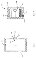
- the upper wall, the lower wall, and the pair of side walls of the closed channel side rail 13 define a hollow interior portion 21, as best shown in Figs. 2 and 3.
- the longitudinal extent of this interior portion 21 within the side rail 13 can, if desired, be limited by a pair of internal plates 22, such as are shown in dotted lines in Fig. 1.
- the plates 22 can be secured to the inner surfaces of the side rail 13 by any conventional means, such as by welding, riveting, bolting, and the like.
- the plates 22 can cooperate with the upper wall, the lower wall, and the pair of side walls of the closed channel side rail 13 to define the interior portion 21 of the side rail in an air-tight manner, although such is not required.
- the interior portion 21 of the side rail 13 may be vented to the atmosphere by one or more vent holes, such as shown at 21a. The purpose for such vent holes 21a will be described below.
- the interior portion 21 may be provided at any desired location within the side rail 13, and multiple interior portions 21 may be provided at different locations within the side rail 13 if desired.
- a similar interior portion (not shown), or a plurality of similar interior portions, may be provided within the other side rail 12, the cross members 14 through 17, or any other structural member of the frame portion 10 of the vehicular body and frame assembly.
- this invention may be practiced by providing similar interior portions within any of the structural members of a unitized body and frame assembly, such as described above.
- a pressurizing device communicates with the interior portion 21 of the side rail 13 for the purpose of selectively increasing the magnitude of the fluid pressure therein under certain conditions.
- the pressurizing device 23 is supported within an opening 24 formed through the side rail 13, although such is not required.
- the illustrated pressurizing device 23 may be secured to the side rail 13 by any conventional means, such as by welding, riveting, bolting, and the like. If desired, a plurality of such pressurizing devices 23 may communicate with the interior portion 21 of the side rail 13.
- the pressurizing device 23 includes a hollow housing 25 having a plurality of apertures 25a formed about the peripheral thereof.
- the apertures 25a are provided such that the interior of the housing 25 of the pressurizing device communicates with the interior portion 21 of the side rail 13.
- the pressurizing device 23 also includes a quantity of a material 26 that is disposed within the interior of the housing 25.
- the material 26 can be embodied as any material that, when properly excited, expands or changes state rapidly so as to cause a rapid increase in the volume thereof. The purpose for such material 26 will be discussed further below.
- a liner 27 may be provided within the interior of the housing 25 of the pressurizing device 23 to cover the apertures 25a.
- the liner 27 can not only prevent the material 26 within the housing 25 from falling out through the apertures 25a, but also can prevent the entry of dirt, water, and other contaminants within the housing 25 through such apertures 25a.
- the pressurizing device 23 further includes an igniter 28 or other actuating mechanism that communicates with the interior of the housing 25.
- the igniter 28 can be embodied as any conventional device that can selectively excite or otherwise cause the material 26 disposed within the housing 25 to expand or change state rapidly so as to cause a rapid increase in volume.
- the pressurizing device 23 can be embodied as an air bag inflator of the type that is generally used in the steering columns of vehicles as a safety device.
- the material 26 contained within the housing 25 of the pressurizing device 23 can, for example, be sodium azide (NaN 3 ) that is mixed with an oxidizer, such as iron oxide Fe 2 O 3 cupric oxide CuO or molybdenum disulfide MoS 2 , and the igniter 28 can be embodied as a conventional pyrotechnic device. Under normal circumstances, the sodium azide material 26 is quite stable. When actuated, the igniter 28 can detonate a small amount of a conventional igniter compound.
- Fig. 5 is a block diagram of a control system, indicated generally at 30, for selectively actuating the igniter 28 of the pressurizing device 23 in the manner described above.
- the control system 30 includes a sensor 31 that generates an output signal to a controller 32.
- the sensor 31 can be embodied as any conventional sensor for detecting any desired operating condition of the vehicle in which the vehicular body and frame assembly is provided.
- the sensor 31 can be an impact sensor that generates an electrical signal to the controller 32 when a portion of the vehicle is impacted, such as during a collision.
- the sensor 31 can be a remote sensor (radar, for example) that generates an electrical signal to the controller 32 in advance of an imminent collision.
- the sensor 31 may be provided on the frame portion 10 of the vehicular body and frame assembly or elsewhere on the vehicle as desired.
- the controller 32 can be responsive to the generation of the signal from the sensor 31 for actuating the igniter 28. To accomplish this, the controller 32 is responsive to the generation of the signal from the sensor 31 for generating a signal to the igniter 28, causing it to be actuated.
- the controller 32 can be embodied as any one of a variety of well known microprocessors or programmable controllers that are commonly available in the market.
- the gas that is released expands rapidly within the housing 25 of the pressurizing device 23.
- Such gas breaks through the liner 27 and enters into the interior portion 21 of the side rail so as to rapidly increase the magnitude of the fluid pressure therein.
- Such fluid pressure increase causes increased forces to be exerted on the inner surfaces of the side rail 13, thereby functioning to strengthen the side rail 13 at the location of the interior portion 21.
- the vent hole 21a can allow a portion of the gas within the interior portion 21 of the side rail 13 to escape therethrough, thereby limiting the amount of increase of the ambient pressure therein and allowing the gas to escape from the interior portion 21 after a predetermined period of time.
- the size of the vent hole 21a can be adjusted to control these parameters.
- the fluid pressure within the interior portion 21 of the side rail 13 can be increased to such a magnitude as to cause deformation of a portion of the side rail 13 prior to impact.
- a situation is illustrated in Fig. 6.
- a portion of the side rail 13 has been expanded outwardly as a result of the increase in the fluid pressure within the interior portion 21 thereof.
- Such expansion can be designed to provide additional strength to the portion of the side rail 13.
- the side rail 13 can be deformed in a controlled manner after a collision.
- Such deformation functions to absorb energy during a collision, thereby providing additional safety to the occupants of the vehicle.
Abstract
Description
- This invention relates in general to body and frame assemblies for vehicles. In particular, this invention relates to an improved structure for a closed channel structural member for use in such a vehicle body and frame assembly that includes an interior portion that can be selectively pressurized under certain conditions, such as during a collision, to provide increased strength and absorb energy.
- Many land vehicles in common use, such as automobiles, vans, and trucks, include a body and frame assembly that is supported upon a plurality of ground-engaging wheels by a resilient suspension system. The structures of known body and frame assemblies can be divided into two general categories, namely, separate and unitized. In a typical separate body and frame assembly, the structural components of the body portion and the frame portion of the vehicle are separate and independent from one another. When assembled, the frame portion of the assembly is resiliently supported upon the vehicle wheels by the suspension system and serves as a platform upon which the body portion of the assembly and other components of the vehicle can be mounted. Separate body and frame assemblies of this general type are found in most older vehicles, but remain in common use today for many relatively large or specialized use modem vehicles, such as large vans, sport utility vehicles, and trucks. In a typical unitized body and frame assembly, the structural components of the body portion and the frame portion are combined into an integral unit that is resiliently supported upon the vehicle wheels by the suspension system. Unitized body and frame assemblies of this general type are found in many relatively small modem vehicles, such as automobiles and minivans.
- Traditionally, the various components of vehicular body and frame assemblies have been formed from open channel structural members, i.e., structural members that have a non-continuous cross sectional shape (such as U-shaped or C-shaped channel members, for example). For example, it is known to use one or more open channel structural members to form the side rails, the cross members, and other components of a ladder frame type of separate body and frame assembly. However, the use of open channel structural members to form the various components of vehicular body and frame assemblies has been found to be undesirable for several reasons. To address this, it has been proposed to form one or more of the components of the vehicular body and frame assemblies from closed channel structural members, i.e., structural members that have a continuous cross sectional shape (such as tubular or box-shaped channel members, for example). This cross sectional shape is advantageous because it provides strength and rigidity to the vehicle body and frame component. Also, closed channel structural members are well suited to be deformed to a desired shape by hydroforming, which is a well known process that uses pressurized fluid supplied within the closed channel structural member to deform it into conformance with a surrounding die. Hydroforming has been found to be a desirable forming process because portions of the closed channel structural member can be quickly and easily deformed to have a complex cross sectional shape.
- Each of the various components of the vehicular body and frame assembly is designed in such a manner as to possess a predetermined amount of strength and rigidity so as to adequately support loads that are placed thereon during operation of the vehicle. When designing the structures of such components, consideration is usually given not only to the relatively small magnitudes of loads that are typically encountered during normal operating conditions of the vehicle, but also to the relatively large magnitudes of loads that might be encountered during extreme operating conditions of the vehicle, such as might occur during a collision. In order to provide maximum safety to the occupants of the vehicle, it is known to design some of all of the components of the vehicular body and frame assembly in such a manner as be capable of accommodating the relatively large magnitudes of the loads that might be encountered during extreme operating conditions of the vehicle. However, by designing these components in this manner, undesirable weight and cost is added to the overall vehicle body and frame assembly, which is inefficient in several regards. Furthermore, in many instances, this additional weight and expense unnecessary because most vehicles are not involved in collisions or operated under other such extreme operating conditions. Thus, it would be desirable to provide an improved structure for a closed channel structural member for use in a vehicle body and frame assembly that is designed to adequately support the relatively small magnitudes of loads that are typically encountered during normal operating conditions of the vehicle, but can be selectively strengthened to accommodate relatively large magnitudes of loads if and when the vehicle encounters extreme operating conditions, such as might occur during a collision.
- This invention relates to an improved structure for a closed channel structural member for use in a vehicle body and frame assembly that includes an interior portion that can be selectively pressurized under certain conditions, such as during a collision, to provide increased strength and absorb energy. The closed channel structural member defines an enclosed interior portion or air space. A pressurizing device communicates with the interior portion and contains a quantity of a chemical material that, when properly excited, will expand rapidly into a gaseous form. An igniter or other structure is provided for exciting the chemical material contained within the pressurizing device under predetermined conditions, such as when a collision occurs. The expansion of the chemical material into a gaseous form rapidly increases the air pressure within the closed channel structural member, thus providing additional strength thereto to absorb energy during the collision. Although deformation of the closed channel structural member may occur as a result of the expansion of the chemical material, it is the containment of the highly pressurized gases within the closed channel structural member that increases the strength thereof during the collision.
- Various objects and advantages of this invention will become apparent to those skilled in the art from the following detailed description of the preferred embodiment, when read in light of the accompanying drawings.
-
- Fig. 1 is an exploded perspective view of a vehicle body and frame assembly including a closed channel structural member and a pressurizing device for selectively pressurizing the interior of the closed channel structural member under certain conditions in accordance with this invention.
- Fig. 2 is an enlarged perspective view of a portion of the closed channel structural member and the pressurizing device illustrated in Fig. 1.
- Fig. 3 is a further enlarged sectional elevational view of the portion of the closed channel structural member and the pressurizing device illustrated in Figs. 1 and 2.
- Fig. 4 is a further enlarged sectional elevational view of the pressurizing device illustrated in Figs. 1, 2, and 3.
- Fig. 5 is a block diagram of a control system for selectively actuating the pressurizing device illustrated in Figs. 1 through 4.
- Fig. 6 is an enlarged perspective view similar to Fig. 2 showing the closed channel structural member after actuation of the pressurizing device.
- Fig. 7 is an enlarged perspective view similar to Fig. 6 showing the closed channel structural member after actuation of the pressurizing device and after it has been subjected the relatively large magnitudes of loads that might be encountered during extreme operating conditions of the vehicle, such as might occur during a collision.
-
- Referring now to the drawings, there is illustrated in Fig. 1 a portion of a vehicular body and frame assembly in accordance with this invention. The illustrated vehicular body and frame assembly is, in large measure, conventional in the art and is intended merely to illustrate one environment in which this invention may be used. Thus, the scope of this invention is not intended to be limited for use with the specific structure for the vehicular body and frame assembly illustrated in Fig. 1 or with vehicular body and frame assemblies in general. On the contrary, as will become apparent below, this invention may be used in any desired environment for the purposes described below.
- The illustrated vehicular body and frame assembly is a separate type of body and frame assembly, including a frame portion, indicated generally at 10, and a body portion, indicated generally at 11. The illustrated
frame portion 10 of the vehicular body and frame assembly is a ladder type frame portion, including a pair of longitudinally extendingside rails transverse cross members side rails frame portion 10 and are generally parallel to one another. Each of theside rails side rails side rails - The
cross members 14 through 17 extend generally perpendicular to theside rails cross members 14 through 17 are spaced apart from one another along the length of theframe portion 13 and can be secured to theside rails side rails cross members 14 through 17 provide lateral and torsional rigidity to theframe portion assembly 10 of the vehicular body and frame assembly. - A plurality of body
mount support brackets 18 are provided on thevehicle frame assembly 10. The illustrated bodymount support brackets 18 are stamped members that are secured to theside rails frame assembly 10 by any conventional means, such as by welding, adhesives, and the like. The bodymount support brackets 18 are provided to facilitate the connection of thebody portion 11 and other various components (not shown) of the vehicle to the vehicular body andframe assembly 10. To accomplish this, each of thebody mount brackets 18 has an opening 18a formed therethrough. Theopenings 18a are sized in accordance with respective body mounts 11a provided on thebody portion 11 of the vehicular body andframe assembly 10. In a manner that is well known in the art, the body mounts 11a are received and supported within theopenings 18a of the bodymount support brackets 18 to connect thebody portion 11 to theframe portion 10. - The upper wall, the lower wall, and the pair of side walls of the closed
channel side rail 13 define a hollowinterior portion 21, as best shown in Figs. 2 and 3. The longitudinal extent of thisinterior portion 21 within theside rail 13 can, if desired, be limited by a pair ofinternal plates 22, such as are shown in dotted lines in Fig. 1. Theplates 22 can be secured to the inner surfaces of theside rail 13 by any conventional means, such as by welding, riveting, bolting, and the like. Theplates 22 can cooperate with the upper wall, the lower wall, and the pair of side walls of the closedchannel side rail 13 to define theinterior portion 21 of the side rail in an air-tight manner, although such is not required. If desired, theinterior portion 21 of theside rail 13 may be vented to the atmosphere by one or more vent holes, such as shown at 21a. The purpose forsuch vent holes 21a will be described below. - The
interior portion 21 may be provided at any desired location within theside rail 13, and multipleinterior portions 21 may be provided at different locations within theside rail 13 if desired. A similar interior portion (not shown), or a plurality of similar interior portions, may be provided within theother side rail 12, thecross members 14 through 17, or any other structural member of theframe portion 10 of the vehicular body and frame assembly. Furthermore, this invention may be practiced by providing similar interior portions within any of the structural members of a unitized body and frame assembly, such as described above. - A pressurizing device, indicated generally at 23, communicates with the
interior portion 21 of theside rail 13 for the purpose of selectively increasing the magnitude of the fluid pressure therein under certain conditions. In the illustrated embodiment, the pressurizingdevice 23 is supported within anopening 24 formed through theside rail 13, although such is not required. The illustratedpressurizing device 23 may be secured to theside rail 13 by any conventional means, such as by welding, riveting, bolting, and the like. If desired, a plurality ofsuch pressurizing devices 23 may communicate with theinterior portion 21 of theside rail 13. - The structure of the pressurizing
device 23 is shown in detail in Fig. 4. As shown therein, the pressurizingdevice 23 includes ahollow housing 25 having a plurality ofapertures 25a formed about the peripheral thereof. Theapertures 25a are provided such that the interior of thehousing 25 of the pressurizing device communicates with theinterior portion 21 of theside rail 13. The pressurizingdevice 23 also includes a quantity of a material 26 that is disposed within the interior of thehousing 25. The material 26 can be embodied as any material that, when properly excited, expands or changes state rapidly so as to cause a rapid increase in the volume thereof. The purpose forsuch material 26 will be discussed further below. If desired, aliner 27 may be provided within the interior of thehousing 25 of the pressurizingdevice 23 to cover theapertures 25a. Theliner 27 can not only prevent thematerial 26 within thehousing 25 from falling out through theapertures 25a, but also can prevent the entry of dirt, water, and other contaminants within thehousing 25 throughsuch apertures 25a. The pressurizingdevice 23 further includes anigniter 28 or other actuating mechanism that communicates with the interior of thehousing 25. Theigniter 28 can be embodied as any conventional device that can selectively excite or otherwise cause thematerial 26 disposed within thehousing 25 to expand or change state rapidly so as to cause a rapid increase in volume. - For example, the pressurizing
device 23 can be embodied as an air bag inflator of the type that is generally used in the steering columns of vehicles as a safety device. In a typical an air bag inflator, thematerial 26 contained within thehousing 25 of the pressurizingdevice 23 can, for example, be sodium azide (NaN3) that is mixed with an oxidizer, such as iron oxide Fe2O3 cupric oxide CuO or molybdenum disulfide MoS2, and theigniter 28 can be embodied as a conventional pyrotechnic device. Under normal circumstances, thesodium azide material 26 is quite stable. When actuated, theigniter 28 can detonate a small amount of a conventional igniter compound. The heat from this ignition starts the reaction of the sodium azide with the oxidizer. As a result, a large volume of nitrogen gas is rapidly generated. This volume of nitrogen gas rapidly increases the magnitude of the fluid pressure within theinterior portion 21 of theside rail 13. Consequently, the strength and rigidity of theside rail 13 is rapidly increased in the vicinity of theinterior portion 21 - Fig. 5 is a block diagram of a control system, indicated generally at 30, for selectively actuating the
igniter 28 of the pressurizingdevice 23 in the manner described above. As shown therein, thecontrol system 30 includes asensor 31 that generates an output signal to acontroller 32. Thesensor 31 can be embodied as any conventional sensor for detecting any desired operating condition of the vehicle in which the vehicular body and frame assembly is provided. For example, thesensor 31 can be an impact sensor that generates an electrical signal to thecontroller 32 when a portion of the vehicle is impacted, such as during a collision. Alternatively, thesensor 31 can be a remote sensor (radar, for example) that generates an electrical signal to thecontroller 32 in advance of an imminent collision. Thesensor 31 may be provided on theframe portion 10 of the vehicular body and frame assembly or elsewhere on the vehicle as desired. Thecontroller 32 can be responsive to the generation of the signal from thesensor 31 for actuating theigniter 28. To accomplish this, thecontroller 32 is responsive to the generation of the signal from thesensor 31 for generating a signal to theigniter 28, causing it to be actuated. Thecontroller 32 can be embodied as any one of a variety of well known microprocessors or programmable controllers that are commonly available in the market. - When the
igniter 28 is actuated in this manner, the gas that is released expands rapidly within thehousing 25 of the pressurizingdevice 23. Such gas breaks through theliner 27 and enters into theinterior portion 21 of the side rail so as to rapidly increase the magnitude of the fluid pressure therein. Such fluid pressure increase causes increased forces to be exerted on the inner surfaces of theside rail 13, thereby functioning to strengthen theside rail 13 at the location of theinterior portion 21. If provided as described above, thevent hole 21a can allow a portion of the gas within theinterior portion 21 of theside rail 13 to escape therethrough, thereby limiting the amount of increase of the ambient pressure therein and allowing the gas to escape from theinterior portion 21 after a predetermined period of time. The size of thevent hole 21a can be adjusted to control these parameters. - If desired, the fluid pressure within the
interior portion 21 of theside rail 13 can be increased to such a magnitude as to cause deformation of a portion of theside rail 13 prior to impact. Such a situation is illustrated in Fig. 6. As shown therein, a portion of theside rail 13 has been expanded outwardly as a result of the increase in the fluid pressure within theinterior portion 21 thereof. Such expansion can be designed to provide additional strength to the portion of theside rail 13. Thereafter, as shown in Fig. 7, theside rail 13 can be deformed in a controlled manner after a collision. Such deformation functions to absorb energy during a collision, thereby providing additional safety to the occupants of the vehicle. - In accordance with the provisions of the patent statutes, the principle and mode of operation of this invention have been explained and illustrated in its preferred embodiment. However, it must be understood that this invention may be practiced otherwise than as specifically explained and illustrated without departing from its spirit or scope.
Claims (10)
- A vehicle frame assembly comprising:a plurality of structural members that are secured together to form a vehicle frame assembly, wherein at least one of said plurality of structural members defines a interior portion; anda pressurizing device that communicates with said interior portion and is responsive to a predetermined condition for increasing the magnitude of pressure in said interior portion.
- The vehicle frame assembly defined in Claim 1 wherein said plurality of structural members includes a pair of side rails and a plurality of cross members that are connected together to form a ladder frame assembly, and wherein said at least one of said plurality of structural members is one of said pair of side rails.
- The vehicle frame assembly defined in Claim 1 wherein said at least one of said plurality of structural members is a closed channel structural member.
- The vehicle frame assembly defined in Claim 3 wherein a pair of internal plates is provided within said closed channel structural member to define said interior portion.
- The vehicle frame assembly defined in Claim 1 wherein said pressurizing device is supported within an opening formed through said at least one of said plurality of structural members.
- The vehicle frame assembly defined in Claim 5 wherein said pressurizing device is secured to said at least one of said plurality of structural members.
- The vehicle frame assembly defined in Claim 1 wherein said pressurizing device includes a hollow housing defining an interior and having a plurality of apertures formed therein such that said interior of said housing communicates with said interior portion of said at least one of said plurality of structural members.
- The vehicle frame assembly defined in Claim 7 wherein said pressurizing device further includes a liner disposed within said interior of said housing to cover said apertures.
- The vehicle frame assembly defined in Claim 7 wherein said pressurizing device further includes a quantity of a material disposed within said interior of said housing that is capable of expanding or changing state rapidly.
- The vehicle frame assembly defined in Claim 7 wherein said pressurizing device further includes a liner disposed within said interior of said housing to cover said apertures and a quantity of a material disposed within said interior of said liner that is capable of expanding or changing state rapidly.
Applications Claiming Priority (2)
| Application Number | Priority Date | Filing Date | Title |
|---|---|---|---|
| US41284802P | 2002-09-23 | 2002-09-23 | |
| US412848P | 2002-09-23 |
Publications (2)
| Publication Number | Publication Date |
|---|---|
| EP1400436A2 true EP1400436A2 (en) | 2004-03-24 |
| EP1400436A3 EP1400436A3 (en) | 2005-02-09 |
Family
ID=31946988
Family Applications (1)
| Application Number | Title | Priority Date | Filing Date |
|---|---|---|---|
| EP03255863A Withdrawn EP1400436A3 (en) | 2002-09-23 | 2003-09-18 | Selectively pressurized structural member for vehicle body and frame assembly |
Country Status (5)
| Country | Link |
|---|---|
| US (1) | US20040056470A1 (en) |
| EP (1) | EP1400436A3 (en) |
| AR (1) | AR041351A1 (en) |
| BR (1) | BR0304192A (en) |
| CA (1) | CA2442050A1 (en) |
Cited By (3)
| Publication number | Priority date | Publication date | Assignee | Title |
|---|---|---|---|---|
| WO2006083209A1 (en) * | 2005-02-01 | 2006-08-10 | Autoliv Development Ab | A safety arrangement |
| WO2009075618A1 (en) * | 2007-12-10 | 2009-06-18 | Autoliv Development Ab | A structural beam for a vehicle and a method of forming a structural beam for a vehicle |
| CN112752482A (en) * | 2020-12-22 | 2021-05-04 | 成都赋阳技术开发有限公司 | Communication gateway box with GPS positioning and heat dissipation functions |
Families Citing this family (2)
| Publication number | Priority date | Publication date | Assignee | Title |
|---|---|---|---|---|
| DE102008020694B4 (en) * | 2008-04-24 | 2012-11-22 | Benteler Automobiltechnik Gmbh | Motor vehicle frame |
| US8167363B2 (en) * | 2009-04-15 | 2012-05-01 | Toyota Motor Engineering & Manufacturing North America, Inc. | Prestressed structural members and methods of making same |
Citations (5)
| Publication number | Priority date | Publication date | Assignee | Title |
|---|---|---|---|---|
| US5845937A (en) * | 1997-02-10 | 1998-12-08 | Morton International, Inc. | Structural assembly |
| US5908204A (en) * | 1996-02-09 | 1999-06-01 | Morton International, Inc. | Stiffening system for structural member of motor vehicle frame |
| DE19918158A1 (en) * | 1999-04-22 | 2000-11-02 | Fraunhofer Ges Forschung | Device for reinforcing the passenger compartment of a motor vehicle |
| DE19963068A1 (en) * | 1999-12-24 | 2001-06-28 | Porsche Ag | Device for motor vehicle body parts deformable with energy conversion in impact accidents has inserts that can be subjected to internal pressure in selected body regions with hollow volumes |
| DE10120138A1 (en) * | 2001-01-18 | 2002-08-01 | Innocenta Ag | Vehicle occupant protection device has impact sensors on long sides of vehicle bodywork |
Family Cites Families (6)
| Publication number | Priority date | Publication date | Assignee | Title |
|---|---|---|---|---|
| US2344378A (en) * | 1938-04-22 | 1944-03-14 | Wagner Max | Chassis, especially for motor vehicles |
| DE2364300A1 (en) * | 1973-12-22 | 1975-06-26 | Porsche Ag | DEVICE FOR ENERGY ABSORPTION FOR VEHICLES, IN PARTICULAR MOTOR VEHICLES |
| US5116080A (en) * | 1990-09-05 | 1992-05-26 | Trw Vehicle Safety Systems Inc. | Air bag inflator and method of making the same |
| US6193303B1 (en) * | 1998-04-03 | 2001-02-27 | Honda Giken Kogyo Kabushiki Kaisha | Control device for controlling rigidity and deformation of car body |
| US6113178A (en) * | 1998-08-31 | 2000-09-05 | Trw Vehicle Safety Systems Inc. | Vehicle energy absorption apparatus |
| US6364399B1 (en) * | 2000-08-10 | 2002-04-02 | Daimlerchrysler Corporation | Pressurized structural member of a motor vehicle frame |
-
2003
- 2003-09-16 US US10/663,149 patent/US20040056470A1/en not_active Abandoned
- 2003-09-18 EP EP03255863A patent/EP1400436A3/en not_active Withdrawn
- 2003-09-22 BR BR0304192-1A patent/BR0304192A/en not_active Application Discontinuation
- 2003-09-22 AR ARP030103446A patent/AR041351A1/en not_active Application Discontinuation
- 2003-09-22 CA CA002442050A patent/CA2442050A1/en not_active Abandoned
Patent Citations (5)
| Publication number | Priority date | Publication date | Assignee | Title |
|---|---|---|---|---|
| US5908204A (en) * | 1996-02-09 | 1999-06-01 | Morton International, Inc. | Stiffening system for structural member of motor vehicle frame |
| US5845937A (en) * | 1997-02-10 | 1998-12-08 | Morton International, Inc. | Structural assembly |
| DE19918158A1 (en) * | 1999-04-22 | 2000-11-02 | Fraunhofer Ges Forschung | Device for reinforcing the passenger compartment of a motor vehicle |
| DE19963068A1 (en) * | 1999-12-24 | 2001-06-28 | Porsche Ag | Device for motor vehicle body parts deformable with energy conversion in impact accidents has inserts that can be subjected to internal pressure in selected body regions with hollow volumes |
| DE10120138A1 (en) * | 2001-01-18 | 2002-08-01 | Innocenta Ag | Vehicle occupant protection device has impact sensors on long sides of vehicle bodywork |
Cited By (4)
| Publication number | Priority date | Publication date | Assignee | Title |
|---|---|---|---|---|
| WO2006083209A1 (en) * | 2005-02-01 | 2006-08-10 | Autoliv Development Ab | A safety arrangement |
| US7416043B2 (en) | 2005-02-01 | 2008-08-26 | Autoliv Developments Ab | Safety arrangement |
| WO2009075618A1 (en) * | 2007-12-10 | 2009-06-18 | Autoliv Development Ab | A structural beam for a vehicle and a method of forming a structural beam for a vehicle |
| CN112752482A (en) * | 2020-12-22 | 2021-05-04 | 成都赋阳技术开发有限公司 | Communication gateway box with GPS positioning and heat dissipation functions |
Also Published As
| Publication number | Publication date |
|---|---|
| BR0304192A (en) | 2004-09-08 |
| CA2442050A1 (en) | 2004-03-23 |
| EP1400436A3 (en) | 2005-02-09 |
| AR041351A1 (en) | 2005-05-11 |
| US20040056470A1 (en) | 2004-03-25 |
Similar Documents
| Publication | Publication Date | Title |
|---|---|---|
| EP1363826B1 (en) | Hybrid space frame for motor vehicle | |
| US5931520A (en) | Light weight instrument panel reinforcement structure | |
| US6293587B1 (en) | Vehicle body and frame assembly including energy absorbing structure | |
| US6434907B1 (en) | Closed channel structural member having internal reinforcement for vehicle body and frame assembly | |
| EP1251061A1 (en) | Floor panel assembly for motor vehicle, having improved strength against side impact | |
| JP2005510405A (en) | Modular chassis for automobiles | |
| EP0800960B1 (en) | Ported passenger airbag module can | |
| EP1400436A2 (en) | Selectively pressurized structural member for vehicle body and frame assembly | |
| US5743590A (en) | Front end for an automobile with a supporting structure | |
| US6161862A (en) | Snap-together airbag module reaction canister | |
| EP1435319A2 (en) | Structural member with internal air tank for a vehicle | |
| JP2009179243A (en) | Front part vehicle body structure for automobile | |
| JP2002200955A (en) | Air bag retainer | |
| US7350805B2 (en) | Airbag device | |
| US7163234B2 (en) | Vehicular cross car beam assembly having an integral air bag inflator | |
| JP2005035403A (en) | Impact- resistant structure for vehicle | |
| JP2008543663A (en) | Car | |
| KR20030096520A (en) | Passenger air bag assembly without door attachment bracket for automobile | |
| US20100011581A1 (en) | Method of manufacturing a vehicle frame assembly | |
| US7393007B2 (en) | Airbag device | |
| CN215475351U (en) | Longitudinal beam for subframe, vehicle subframe and vehicle | |
| GB2362138A (en) | Inflatable reinforcing element | |
| KR0126281Y1 (en) | Attachment structure of aluminium frame | |
| KR200260745Y1 (en) | reinforcement structure of sill side portion for vehicle | |
| JPH1035398A (en) | Device for absorbing collitional energy given to side part of car body |
Legal Events
| Date | Code | Title | Description |
|---|---|---|---|
| PUAI | Public reference made under article 153(3) epc to a published international application that has entered the european phase |
Free format text: ORIGINAL CODE: 0009012 |
|
| AK | Designated contracting states |
Kind code of ref document: A2 Designated state(s): AT BE BG CH CY CZ DE DK EE ES FI FR GB GR HU IE IT LI LU MC NL PT RO SE SI SK TR |
|
| AX | Request for extension of the european patent |
Extension state: AL LT LV MK |
|
| PUAL | Search report despatched |
Free format text: ORIGINAL CODE: 0009013 |
|
| AK | Designated contracting states |
Kind code of ref document: A3 Designated state(s): AT BE BG CH CY CZ DE DK EE ES FI FR GB GR HU IE IT LI LU MC NL PT RO SE SI SK TR |
|
| AX | Request for extension of the european patent |
Extension state: AL LT LV MK |
|
| 17P | Request for examination filed |
Effective date: 20050803 |
|
| AKX | Designation fees paid |
Designated state(s): AT BE BG CH CY CZ DE DK EE ES FI FR GB GR HU IE IT LI LU MC NL PT RO SE SI SK TR |
|
| 17Q | First examination report despatched |
Effective date: 20060711 |
|
| STAA | Information on the status of an ep patent application or granted ep patent |
Free format text: STATUS: THE APPLICATION IS DEEMED TO BE WITHDRAWN |
|
| 18D | Application deemed to be withdrawn |
Effective date: 20061122 |