EP1400435A2 - Driving assist system for vehicle - Google Patents
Driving assist system for vehicle Download PDFInfo
- Publication number
- EP1400435A2 EP1400435A2 EP03018335A EP03018335A EP1400435A2 EP 1400435 A2 EP1400435 A2 EP 1400435A2 EP 03018335 A EP03018335 A EP 03018335A EP 03018335 A EP03018335 A EP 03018335A EP 1400435 A2 EP1400435 A2 EP 1400435A2
- Authority
- EP
- European Patent Office
- Prior art keywords
- reaction force
- vehicle
- steering
- risk potential
- force adjustment
- Prior art date
- Legal status (The legal status is an assumption and is not a legal conclusion. Google has not performed a legal analysis and makes no representation as to the accuracy of the status listed.)
- Granted
Links
Images


Classifications
-
- B—PERFORMING OPERATIONS; TRANSPORTING
- B60—VEHICLES IN GENERAL
- B60W—CONJOINT CONTROL OF VEHICLE SUB-UNITS OF DIFFERENT TYPE OR DIFFERENT FUNCTION; CONTROL SYSTEMS SPECIALLY ADAPTED FOR HYBRID VEHICLES; ROAD VEHICLE DRIVE CONTROL SYSTEMS FOR PURPOSES NOT RELATED TO THE CONTROL OF A PARTICULAR SUB-UNIT
- B60W40/00—Estimation or calculation of non-directly measurable driving parameters for road vehicle drive control systems not related to the control of a particular sub unit, e.g. by using mathematical models
- B60W40/02—Estimation or calculation of non-directly measurable driving parameters for road vehicle drive control systems not related to the control of a particular sub unit, e.g. by using mathematical models related to ambient conditions
-
- B—PERFORMING OPERATIONS; TRANSPORTING
- B60—VEHICLES IN GENERAL
- B60W—CONJOINT CONTROL OF VEHICLE SUB-UNITS OF DIFFERENT TYPE OR DIFFERENT FUNCTION; CONTROL SYSTEMS SPECIALLY ADAPTED FOR HYBRID VEHICLES; ROAD VEHICLE DRIVE CONTROL SYSTEMS FOR PURPOSES NOT RELATED TO THE CONTROL OF A PARTICULAR SUB-UNIT
- B60W40/00—Estimation or calculation of non-directly measurable driving parameters for road vehicle drive control systems not related to the control of a particular sub unit, e.g. by using mathematical models
- B60W40/08—Estimation or calculation of non-directly measurable driving parameters for road vehicle drive control systems not related to the control of a particular sub unit, e.g. by using mathematical models related to drivers or passengers
-
- B—PERFORMING OPERATIONS; TRANSPORTING
- B60—VEHICLES IN GENERAL
- B60W—CONJOINT CONTROL OF VEHICLE SUB-UNITS OF DIFFERENT TYPE OR DIFFERENT FUNCTION; CONTROL SYSTEMS SPECIALLY ADAPTED FOR HYBRID VEHICLES; ROAD VEHICLE DRIVE CONTROL SYSTEMS FOR PURPOSES NOT RELATED TO THE CONTROL OF A PARTICULAR SUB-UNIT
- B60W40/00—Estimation or calculation of non-directly measurable driving parameters for road vehicle drive control systems not related to the control of a particular sub unit, e.g. by using mathematical models
- B60W40/10—Estimation or calculation of non-directly measurable driving parameters for road vehicle drive control systems not related to the control of a particular sub unit, e.g. by using mathematical models related to vehicle motion
-
- B—PERFORMING OPERATIONS; TRANSPORTING
- B62—LAND VEHICLES FOR TRAVELLING OTHERWISE THAN ON RAILS
- B62D—MOTOR VEHICLES; TRAILERS
- B62D15/00—Steering not otherwise provided for
- B62D15/02—Steering position indicators ; Steering position determination; Steering aids
-
- B—PERFORMING OPERATIONS; TRANSPORTING
- B62—LAND VEHICLES FOR TRAVELLING OTHERWISE THAN ON RAILS
- B62D—MOTOR VEHICLES; TRAILERS
- B62D6/00—Arrangements for automatically controlling steering depending on driving conditions sensed and responded to, e.g. control circuits
-
- B—PERFORMING OPERATIONS; TRANSPORTING
- B60—VEHICLES IN GENERAL
- B60K—ARRANGEMENT OR MOUNTING OF PROPULSION UNITS OR OF TRANSMISSIONS IN VEHICLES; ARRANGEMENT OR MOUNTING OF PLURAL DIVERSE PRIME-MOVERS IN VEHICLES; AUXILIARY DRIVES FOR VEHICLES; INSTRUMENTATION OR DASHBOARDS FOR VEHICLES; ARRANGEMENTS IN CONNECTION WITH COOLING, AIR INTAKE, GAS EXHAUST OR FUEL SUPPLY OF PROPULSION UNITS IN VEHICLES
- B60K26/00—Arrangement or mounting of propulsion-unit control devices in vehicles
- B60K26/02—Arrangement or mounting of propulsion-unit control devices in vehicles of initiating means or elements
- B60K26/021—Arrangement or mounting of propulsion-unit control devices in vehicles of initiating means or elements with means for providing feel, e.g. by changing pedal force characteristics
-
- B—PERFORMING OPERATIONS; TRANSPORTING
- B60—VEHICLES IN GENERAL
- B60K—ARRANGEMENT OR MOUNTING OF PROPULSION UNITS OR OF TRANSMISSIONS IN VEHICLES; ARRANGEMENT OR MOUNTING OF PLURAL DIVERSE PRIME-MOVERS IN VEHICLES; AUXILIARY DRIVES FOR VEHICLES; INSTRUMENTATION OR DASHBOARDS FOR VEHICLES; ARRANGEMENTS IN CONNECTION WITH COOLING, AIR INTAKE, GAS EXHAUST OR FUEL SUPPLY OF PROPULSION UNITS IN VEHICLES
- B60K31/00—Vehicle fittings, acting on a single sub-unit only, for automatically controlling vehicle speed, i.e. preventing speed from exceeding an arbitrarily established velocity or maintaining speed at a particular velocity, as selected by the vehicle operator
- B60K31/18—Vehicle fittings, acting on a single sub-unit only, for automatically controlling vehicle speed, i.e. preventing speed from exceeding an arbitrarily established velocity or maintaining speed at a particular velocity, as selected by the vehicle operator including a device to audibly, visibly, or otherwise signal the existence of unusual or unintended speed
-
- B—PERFORMING OPERATIONS; TRANSPORTING
- B60—VEHICLES IN GENERAL
- B60W—CONJOINT CONTROL OF VEHICLE SUB-UNITS OF DIFFERENT TYPE OR DIFFERENT FUNCTION; CONTROL SYSTEMS SPECIALLY ADAPTED FOR HYBRID VEHICLES; ROAD VEHICLE DRIVE CONTROL SYSTEMS FOR PURPOSES NOT RELATED TO THE CONTROL OF A PARTICULAR SUB-UNIT
- B60W30/00—Purposes of road vehicle drive control systems not related to the control of a particular sub-unit, e.g. of systems using conjoint control of vehicle sub-units
- B60W30/08—Active safety systems predicting or avoiding probable or impending collision or attempting to minimise its consequences
Definitions
- the present invention relates to a technology for assisting driver operations, and more specifically, it relates to a driving assist system for a vehicle that assists operations performed by the driver.
- Systems employed to assist driver operations in the related art include the system disclosed in Japanese Laid Open Patent Publication No. H 10-211886. This system detects the conditions around the vehicle and determines any latent risk potential that may exist. Then, the system inhibits a steering operation that could lead to an undesirable situation by controlling the steering assist torque based upon the calculated risk potential.
- the present invention is to provide a driving assist system for a vehicle capable of communicating a risk potential in a manner appropriate to the state of the driver's perception.
- a driving assist system for a vehicle comprises a traveling condition recognition means (10, 20, 50, 92) for detecting a state of the vehicle and a traveling environment of the vehicle; a risk potential calculation means (30B, 40B) for calculating a risk potential present around the vehicle based upon detection results obtained by the traveling condition recognition means (10, 20, 50, 92); a reaction force adjustment means (30B, 30C, 40B, 40C) for adjusting reaction force characteristics of a vehicle operating device based upon the risk potential calculated by the risk potential calculation means (30B, 40B); an external influence detection means (30D, 40) for detecting an external influence which will affect an operation of the vehicle operating device by a driver; and a reaction force correction means (30B, 40B) for correcting the reaction force characteristics of the vehicle operating device adjusted by the reaction force adjustment means (30B, 30C, 40B, 40C) , based upon detection results obtained by the external influence detection means (30D, 40).
- a vehicle driving assist method detects a state of a vehicle and a traveling environment of the vehicle; calculates a risk potential present around the vehicle based upon the state of the vehicle and the traveling environment of the vehicle; adjusts reaction force characteristics of a vehicle operating device based upon the risk potential; detects an external influence which will affect an operation of the vehicle operating device by a driver; and corrects the reaction force characteristics of the vehicle operating device adjusted according to the risk potential, based upon the external influence.
- FIG. 1 shows the system configuration of a driving assist system 1 achieved in the first embodiment
- FIG. 2 illustrates the structure of a vehicle equipped with the driving assist system 1.
- a laser radar 10 which may be mounted at the front grille or the bumper of the vehicle, scans an area ahead of the vehicle by propagating infrared pulses along the horizontal direction.
- the laser radar 10 measures reflected waves of the infrared pulses reflected from a plurality of reflecting objects (normally, the rear end of the preceding vehicle and the like) present ahead of the vehicle and detects the distance (a vehicle distance) and the relative speed to the preceding vehicle based upon the length of time that the reflected waves take to reach the laser radar 10.
- the vehicle distance and the relative speed thus detected are output to a controller 30.
- the front area scanned by the laser radar 10 ranges over approximately 6 degrees to each side of the longitudinal centerline of the vehicle and the laser radar 10 detects obstacles present within this range.
- a vehicle speed sensor 20 detects the traveling speed at which the vehicle is currently traveling based upon the rotational rate or the like of the wheels and outputs the detected vehicle speed to the controller 30.
- a shift position sensor 80 detects a position of a gear shift lever (not shown) and outputs the detected shift position to the controller 30.
- the controller 30 comprising a CPU and CPU peripheral components such as a ROM and a RAM.
- the controller 30 constitutes a RP calculation unit (a RP calculation unit) 30A, a reaction force calculation/correction unit (a RF unit) 30B, an accelerator pedal reaction force control unit (an AF control unit) 30C and a RL detection unit (a RL detection unit) 30D by adopting a specific software mode at the CPU.
- the RP calculation unit 30A calculates a risk potential (RP) attributable to the state in which the vehicle is traveling and the surrounding environment based upon the signals input from the laser radar 10 and the vehicle speed sensor 20.
- the RP calculated at the RP calculation unit 30A is output to the RF unit 30B.
- a servomotor 60 and a pedal sensor 61 are connected via a link mechanism to an accelerator pedal 70 .
- the pedal sensor 61 detects a position of the accelerator pedal 70, in other words, an operation amount S by which the accelerator pedal 70 is depressed, which has been converted to a rotational angle of the servomotor 60 via the link mechanism.
- the pedal sensor 61 outputs the detected operation amount S to the controller 30.
- the AF control unit 30C calculates an accelerator pedal reaction force F to be generated at the accelerator pedal 70. Then, the AF control unit 30C controls the torque generated at the servomotor 60 and the rotational angle of the servomotor 60 so as to achieve the accelerator pedal reaction force F that has been calculated and thus controls the reaction force generated at the accelerator pedal 70 arbitrarily. It is to be noted that in a normal situation in which the accelerator pedal reaction force control is not implemented, the accelerator pedal reaction force characteristics are set so that, for instance, the accelerator pedal reaction force F increases linearly as the operation amount S becomes larger. The normal accelerator pedal reaction force characteristics may be achieved by a spring force imparted by a torsion spring (not shown) provided at the center of the rotation of the accelerator pedal 70.
- the RL detection unit 30D calculates a running resistance RL of the vehicle based upon the vehicle speed input from the vehicle speed sensor 20, the operation amount S input from the pedal sensor 61 and a shift position signal input from the shift position sensor 80.
- the running resistance RL calculated at the RL detection unit 30D is output to the RF unit 30B.
- the RF unit 30B calculates a reaction force increase quantity (a reaction force adjustment quantity or a RF increase quantity) ⁇ F by which the pedal reaction force F generated at the accelerator pedal 70 should be increased based upon the RP calculated at the RP calculation unit 30A. Furthermore, the RF unit 30B corrects the RF increase quantity ⁇ F based upon the running resistance RL calculated at the RL detection unit 30D. It is to be noted that the running resistance RL is used as a reference when making a decision with regard to the driver's perception of the pedal reaction force F. Details of the accelerator pedal reaction force control are to be provided later.
- the RP calculation unit 30A calculates a "time-to-contact” (TTC) and a “time headway” (THW) in relation to the preceding vehicle based upon the vehicle speed Vf, the preceding vehicle speed Va, the relative vehicle speed Vr and the relative distance D between the subject vehicle and the preceding vehicle.
- TTC and the THW may be calculated by using (expression 1) and (expression 2) presented below. It is to be noted that the relative vehicle speed Vr is calculated as Vf-Va.
- the TTC is a physical quantity that indicates the current proximity between the subject vehicle and the preceding vehicle.
- the TTC is a value that indicates how many seconds after the subject vehicle will come into contact with the preceding vehicle if the current traveling state is sustained, i. e. , if the relative vehicle speed Vr remains constant.
- the THW is a value that indicates an estimated degree to which the TTC will be affected subsequently if the subject vehicle is trailing the preceding vehicle, i.e., following the preceding vehicle with a matching speed. It is to be noted that if the subject vehicle is trailing the preceding vehicle, the vehicle speed Vf is equal to the preceding vehicle speed Va, and thus, the preceding vehicle speed Va instead of the vehicle speed Vf may be used to calculate the THW.
- the RP calculation unit 30A calculates the RP for the subject vehicle based upon the TTC and the THW.
- the RP is defined in (expression 3) presented below by using the reciprocal 1/TTC of the TTC value and the reciprocal 1/THW of the THW value.
- the RL detection unit 30D calculates the current acceleration ac of the subject vehicle based upon the vehicle speed Vf and then calculates the torque that is actually generated (the actual torque) Tr at the subject vehicle.
- the RL detection unit 30D calculates a command value (torque command value) Tc for the torque to be generated at the subject vehicle based upon the accelerator pedal operation amount S and the shift position. Values that may be assumed for the torque command value Tc should be set in advance in a map in relation to the operation amount S and the shift position.
- the RL detection unit 30D calculates the running resistance RL of the subject vehicle as the difference between the actual torque and the torque Tr command value Tc.
- an external influence which is likely to affect the driver's perception and also affect the driver's operation of a vehicle operating device, such as the accelerator pedal 70 can be detected.
- Such an external influence likely to affect the driver's perception may be, for instance, the state of pedal depression.
- the state of pedal depression is estimated in correspondence to the running resistance RL of the subject vehicle.
- the driver's perception of the pedal reaction force F changes in conformance to the state of the depression of the accelerator pedal 70.
- the driver's perception is active and thus the driver senses any change in the pedal reaction force F keenly.
- the accelerator pedal 70 is held in the depressed position, on the other hand, the driver's perception is passive and not as keen. While the driver brings the accelerator pedal 70 back to the released position, the driver's perception becomes dulled and thus it becomes more difficult for the driver to sense a change in the pedal reaction force F.
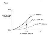
- FIG. 3 presents an example of the relationship between the RF increase quantity ⁇ F by which the reaction force is increased at the accelerator pedal 70 and the driver's perception of the pedal reaction force F.
- driver senses the pedal reaction force F more keenly while pressing down on the accelerator pedal 70 (indicated by a solid line), compared to while he is holding the accelerator pedal 70 in the depressed state (indicated by a broken line) or while the accelerator pedal 70 is brought back to the released position (indicated by a one-point chain line).
- the driver's perception of the pedal reaction force F is keener while the accelerator pedal 70 is held down compared to while the accelerator pedal 70 is being released.
- the driver's perception is also keener while he is pressing down on the accelerator pedal 70 compared to while the accelerator pedal 70 is held down.
- the RF increase quantity ⁇ F by which the pedal reaction force F is to be increased is corrected in conformance to the state of the depression of the accelerator pedal 70 so as to execute the accelerator pedal reaction force control by reflecting the current state of the driver's perception in the first embodiment of the present invention.
- the running resistance RL is used to estimate the state of depression of the accelerator pedal 70, as mentioned earlier.
- FIG. 4A shows an example of the relationship between the running resistance RL and the depressed state of the accelerator pedal 70 in terms of the frequency of pedal operation in each depressed state.
- FIGS. 4B ⁇ 4D outline the accelerator pedal reaction force control implemented in correspondence to the running resistance RL, with a solid line Fini representing the normal accelerator pedal reaction force characteristics whereby the pedal reaction force F changes in conformance to the operation amount S.
- the driver tends to step on the accelerator pedal 70 more readily when the level of the running resistance RL is high, i.e. the actual torque Tr is smaller than the torque command value Tc.
- the driver also tends to release the accelerator pedal 70 when the level of the running resistance RL is small, i.e. the actual torque Tr is larger than the torque command value Tc.
- the driver tends to hold the position of the accelerator pedal 70 when the driving resistance RL is at an intermediate level, i.e. when the actual torque Tr is substantially equal to the torque command value Tc.
- the vehicle may be traveling uphill, for instance, when the running resistance RL is high, whereas the vehicle may be traveling downhill when the running resistance RL is low.
- the vehicle may be traveling on a flat road when the running resistance RL is at an intermediate level.
- a road condition e. g. , uphill or downhill
- Such an external influence affects the driving operations performed by the driver and, more specifically, it affects the manner in which the driver depresses the accelerator pedal 70 and ultimately affects the driver's perception of the pedal reaction force F as well.
- the RF unit 30B calculates the RF increase quantity ⁇ F to be incorporated into the normal accelerator pedal reaction force characteristics in correspondence to the RP.
- the RF increase quantity ⁇ F may be calculated by using, for instance, (expression 6) presented below.
- ⁇ F k x RPn k in the expression above represents a constant set to an appropriate value.
- the RF increase quantity ⁇ F increases exponentially as the RP increases.
- the RF unit 30B then corrects the RF increase quantity ⁇ F in correspondence to the running resistance RL as shown in FIGS. 4B ⁇ 4D so as to ensure that the driver's perception of the pedal reaction force remains constant at all times. Namely, for a given level of RP, it reduces the RF increase quantity ⁇ F if the running resistance RL is high and increases the RF increase quantity ⁇ F if the running resistance RL is low. In this example, the RF increase quantity ⁇ F is corrected by adjusting the exponent n in the (expression 6) in conformance to the level of the running resistance RL.
- FIG. 5 shows the relationship between the RF increase quantity ⁇ F and the RP, which vary as the running resistance RL changes.
- FIG. 5 shows the characteristics of the RF increase quantity ⁇ F when the running resistance RL is high (RL > RLa) by a solid line, the characteristics of the RF increase quantity ⁇ F when the running resistance level is intermediate (RLb ⁇ RL ⁇ RLa) by a broken line, and the characteristics of the RF increase quantity ⁇ F when the running resistance RL is low (RL ⁇ RLb) by a one-point chain line.
- n1 set for the exponent n when the running resistance RL is high, n2 set for the exponent n when the running resistance level is intermediate and n3 set for the exponent n when the running resistance RL is low respectively assume appropriate value settings so as to achieve a relationship expressed as n1 ⁇ n2 ⁇ n3.
- the RF increase quantity ⁇ F is set to ⁇ Fa if the running resistance RL is high, the RF increase quantity ⁇ F is set to ⁇ Fb if the running resistance level is intermediate and the RF increase quantity ⁇ F is set to ⁇ Fc if the running resistance RL is low with ⁇ Fa, ⁇ Fb and ⁇ Fc satisfying a relationship expressed as ⁇ Fa ⁇ ⁇ Fb ⁇ ⁇ Fc.
- the RF unit 30B corrects the RF increase quantity ⁇ F by adjusting the exponent n in (expression 6) used to calculate the RF increase quantity ⁇ F in correspondence to the level of the running resistance RL input from the RL detection unit 30D. Then it outputs the corrected value to the AF control unit 30C so that the servomotor 60 is controlled based upon the corrected value.
- pedal reaction force control that ensures that the driver's perception of the level of the pedal reaction force F generated in correspondence to the RP remains constant at all times regardless of the level of the running resistance RL is achieved.
- step S101 the traveling conditions such as the vehicle speed Vf, the vehicle distance D and the relative vehicle speed Vr to the preceding vehicle, and the preceding vehicle speed Va detected by the laser radar 10 and the vehicle speed sensor 20 are read.
- step S102 the operating conditions detected by the pedal sensor 61 and the shift position sensor 80, i. e. , the accelerator pedal operation amount S and the shift position of the gear shift sensor, are read.
- step S103 the TTC and the THW are calculated by using (expression 1) and (expression 2) based upon the traveling conditions having been read in step S101 and also, the RP is calculated for the subject vehicle by using (expression 3).
- step S104 the actual torque Tr is calculated based upon the vehicle speed Vf read in step S101.
- step S105 the torque command value Tc is calculated based upon the operation amount S and the shift position read in step S102.
- step S106 the running resistance RL is calculated by using (expression 5).
- step S107 a decision is made as to whether or not the running resistance RL that has been calculated in step S106 is larger than the threshold RLa. If an affirmative decision is made in step S107, the operation proceeds to step S108.
- step S108 the RF increase quantity ⁇ F by which the accelerator pedal reaction force F is to increase when the running resistance RL is high (RL > RLa) is calculated.
- the RF increase quantity ⁇ F is defined in (expression 7) presented below when the running resistance RL is higher than RLa.
- step S109 a command is output to the AF control unit 30C so as to increase the accelerator pedal reaction force by the RF increase quantity ⁇ F calculated in step S108.
- the AF control unit 30C then controls the servomotor 60 so as to generate the pedal reaction force F achieved by incorporating the RF increase quantity ⁇ F into the normal accelerator pedal reaction force characteristics.
- step S110 a decision is made as to whether or not the running resistance RL is equal to or smaller than the threshold value RLa and also equal to or greater than the threshold value RLb. If an affirmative decision is made in step S110, the operation proceeds to step S111.
- step S111 the reaction force increase quantity ⁇ F to be generated when the running resistance RL is at an intermediate level (RLb ⁇ RL ⁇ RLa) is calculated.
- the RF increase quantity ⁇ F calculated at this time is defined in (expression 8) presented below.
- step S110 the operation proceeds to step S112.
- step S112 the RF increase quantity ⁇ F to be generated when the running resistance RL is low (RL ⁇ RLb) is calculated.
- the RF increase quantity ⁇ F calculated at this time is defined in (expression 9) presented below.
- step S109 a command is output to the AF control unit 30C so as to increase the accelerator pedal reaction force by the RF increase quantity ⁇ F that has been calculated.
- FIG. 7 illustrates the function of the driving assist system 1 achieved in the first embodiment.
- the arrows in FIG. 7 each schematically indicate the relationship between the RF increase quantity ⁇ F and the operation amount S corresponding to a given level of running resistance RL.
- the RF increase quantity ⁇ F by which the accelerator pedal reaction force is increased when the driver is in a more perceptive state, e. g. , when the driver is purposefully stepping on the accelerator pedal 70 and the driving resistance RL is high, is smaller than the RF increase quantity ⁇ F generated when the running resistance RL is at an intermediate level with the accelerator pedal 70 held in a depressed state.
- the RF increase quantity ⁇ F by which the reaction force is increased when the driver is in a less perceptive state, e. g. , when the accelerator pedal 70 is being released is greater than the RF increase quantity ⁇ F corresponding to an intermediate running resistance level.
- FIG. 8 shows the system configuration of the driving assist system 2 achieved in the second embodiment
- FIG. 9 shows the structure of a vehicle equipped with the driving assist system 2.
- the same reference numerals are assigned to components having functions similar to those in the first embodiment. The following explanation focuses on the differences from the first embodiment.
- a laser radar 10 detects any obstacle that is present to the front left or the front right of the vehicle as well as any obstacle present straight ahead of the vehicle within its scanning range.
- the laser radar 10 detects the distance and the relative speed to, for instance, a vehicle on an adjacent lane or an oncoming vehicle, and the direction in which the other vehicle is present (the relative angle).
- a front camera 50 which may be a compact CCD camera or CMOS camera mounted at the top of the windshield.
- the front camera 50 detects the condition of the road ahead of the subject vehicle as an image and outputs the image signal to a controller 40.
- the detection area of the front camera 50 is approximately 30 degrees to each side of the longitudinal centerline of the subject vehicle, and a view of the road ahead of the subject vehicle within this range is taken in as an image.
- the controller 40 ascertains obstacle conditions around the subject vehicle by executing image processing on the image signals input from the front camera 50.
- a steering angle sensor 92 is an angle sensor mounted, for instance, near the steering column or a steering wheel 90.
- the steering angle sensor 92 detects the rotational angle, i. e. , the steering angle, of the steering wheel 90 and outputs the detected angle to the controller 40.
- the controller 40 ascertains the operating state of the subject vehicle based upon the steering angle input from the steering angle sensor 92.
- the controller 40 implements steering reaction force control in correspondence to the RP based upon the obstacle condition around the subject vehicle and the operating state of the subject vehicle.
- a risk potential calculation unit (a RP calculation unit) 40A calculates the RP for the subject vehicle based upon the signals input from the laser radar 10, a vehicle speed sensor 20 and the front camera 50. During this process, the RP calculation unit 40A calculates the RP present along the lateral direction relative to the subject vehicle by using the relative distance D to an obstacle present around the subject vehicle and the relative speed Vr. The lateral RP thus calculated is output to a reaction force calculation/correction unit (a RF unit) 40B.
- a steering reaction force control unit (a SF control unit) 40C controls the torque generated at a servomotor 91 built into the steering system of the subject vehicle in response to a command issued by the RF unit 40B.
- the servomotor 91 arbitrarily controls the steering reaction force generated while the driver operates the steering wheel 90 by controlling the torque to be generated.
- a self-aligning torque is generated at the tires and thus, a steering reaction force that will act so as to reset the steering wheel 90 to the neutral position is generated.
- a reaction force adjustment quantity corresponding to the lateral RP relative to the subject vehicle is incorporated into the steering reaction force attributable to the self-aligning torque characteristics (SAT characteristics) to achieve control of the steering reaction force.
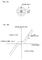
- FIGS. 10A and 10B and FIGS. 11A and 11B illustrate the basic principle of the steering reaction force control achieved in the second embodiment.
- FIGS. 10A and 11A each indicate the steering direction and a direction along which the RP is applied to the subject vehicle.
- the horizontal axis represents the steering angle ⁇ which assumes positive values for steering the vehicle to the right and the vertical axis represents the steering reaction force T which assumes positive values in the direction along which the steering wheel, having been steered to the right, is reset to the neutral position.
- the steering wheel 90 is at the neutral position and the current steering angle ⁇ is 0.
- the SAT characteristics indicated by the one-point chain line are such that the steering reaction force T increases as the steering angle ⁇ becomes larger.
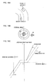
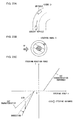
- FIG. 12A shows a specific example of traveling conditions corresponding to scene 1.
- FIG. 12B shows the steering direction and the direction from which the RP originates in scene 1
- FIG. 12C shows the steering reaction force characteristics to the steering angle.
- an obstacle such as an oncoming vehicle is present to the front right of the subject vehicle while the subject vehicle is traveling in a right curve.
- the direction in which the road curves and the direction in which the RP is present match in scene 1.
- the risk potential which is applied to the subject vehicle along a lateral direction is represented as a RPc.
- the RP calculation unit 40A calculates the RPc present at the right of the subject vehicle traveling in the right curve based upon the distance D and the relative speed Vr between the subject vehicle and the oncoming vehicle, and the direction along which the obstacle is present in relation to the subject vehicle.
- the direction along which the obstacle is present is represented as the relative angle ⁇ r between the subject vehicle and the obstacle in this example. While the relative angle ⁇ r may assume a positive value when an obstacle is present to the right and may assume a negative value when an obstacle is present to the left, the RPc is calculated by using the absolute value of the relative angle ⁇ r to simplify the explanation in the example.
- the RPc corresponding to the obstacle present to the front right may be calculated, for instance, by using the TTC, in particular, by using the component of the TTC along the lateral direction relative to the subject vehicle.
- the TTC represents the margin of time left before the subject vehicle comes into contact with the obstacle and is calculated by using (expression 1).
- the RF unit 40B calculates the RF adjustment quantity ⁇ Ta to be incorporated into the SAT characteristics.
- FIG. 13 presents an example of the relationship between the RF adjustment quantity ⁇ Ta and the level of the RPc.
- the RF adjustment quantity ⁇ Ta which is defined as a function g1 (RPc) of the RPc, increases as the level of the RPc rises as shown in FIG. 13.
- the RF adjustment quantity ⁇ Ta can be defined in (expression 11) presented below. m in the expression above is a constant which is set to an appropriate value in advance.
- the RF unit 40B outputs the calculated RF adjustment quantity ⁇ Ta ( ⁇ Ta ⁇ 0) to be incorporated into the SAT characteristics to the SF control unit 40C which, in turn, implements the steering reaction force control by incorporating the RF adjustment quantity ⁇ Ta into the SAT characteristics.
- the reaction force T to be generated for steering the vehicle to the right is raised and the reaction force T to be generated for steering the vehicle to the left is lowered by incorporating a constant RF adjustment quantity ⁇ Ta into the SAT characteristics indicated by the one-point chain line in scene 1. It is to be noted that while the SAT characteristics change in correspondence to the vehicle speed, the RF adjustment quantity ⁇ Ta corresponding to the RPc is added when the SAT characteristics change as well.
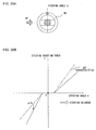
- FIG. 14A shows a specific example of traveling conditions corresponding to scene 2.
- FIG. 14B shows the steering direction and the direction from which the RPc originates in scene 2
- FIG. 14C shows the steering reaction force characteristics to the steering angle.
- an obstacle such as a parked vehicle is present to the front left of the subject vehicle while the subject vehicle is traveling in a right curve. This means that the direction in which the road curves and the direction in which the RPc is present do not match in scene 2.
- the RP calculation unit 40A calculates the RPc present to the left of the subject vehicle traveling in the right curve. As in scene 1 explained earlier, the RPc is calculated by using (expression 10).
- the RF unit 40B calculates the RF adjustment quantity ⁇ Ta as (-m x RPc) , ⁇ Ta ⁇ 0, corresponding to the RPc by using (expression 11).
- the RF unit 40B incorporates the calculated RF adjustment quantity ⁇ Ta ( ⁇ Ta ⁇ 0) into the SAT characteristics as shown in FIG. 14C so as to set the steering reaction force characteristics corresponding to scene 2. Consequently, the steering reaction force T to be generated for steering the subject vehicle to the right is lowered and the steering reaction force T to be generated for steering the vehicle to the left is raised.
- the driver drives the vehicle in a right curve by maintaining the steering wheel balance while sensing the steering reaction force T generated by the self-aligning torque. For this reason, if the steering reaction force T is reduced while the vehicle is steered to the right, it becomes difficult to communicate the RPc to the driver through the steering reaction force T. Moreover, the lowered steering reaction force T may disconcert the driver as well.
- the steering reaction force T is reduced by a constant degree and, at the same time, the inclination of the steering reaction force characteristics to the steering angle is increased for steering the vehicle to the left.
- the driver is made to experience a degree of resistance if he tries to steer the vehicle to the left so that he becomes aware of the RPc present to the left of the subject vehicle.
- the steering reaction force T is raised when the vehicle being steered to the left by correcting the RF adjustment quantity ⁇ Ta for steering the vehicle to the left with a correction quantity H corresponding to the steering angle ⁇ .
- the correction quantity H which is in proportion to the steering angle ⁇ , may be defined in (expression 12) presented below.
- H h1 (RPc) x ⁇
- h1 (RPc) in the expression above represents a function of the RPc and is a coefficient used to determine the correction quantity H.
- FIG. 15 presents an example of the relationship between the correction coefficient h1 (RPc) and the RPc.
- the correction coefficient h1 (RPc), which is in proportion to the RPc as shown in FIG. 15, may be defined in (expression 13) presented below by using a constant n1, for instance.
- h1 (RPc) n1 x RPc
- the RF adjustment quantity ⁇ Ta for steering the vehicle to the left in scene 2 is defined in (expression 14) presented below. It is to be noted that the RF adjustment quantity ⁇ Ta is calculated by using the absolute value of the correction quantity H.
- the correction quantity H is incorporated for steering the vehicle to the left to correct the inclination of the SAT characteristics to further raise the reaction force T for steering the vehicle to the left.
- FIG. 16A shows a specific example of traveling conditions corresponding to scene 3.
- FIG. 16B shows the steering direction and the direction from which the RPc originates in scene 3
- FIG. 16C shows the steering reaction force characteristics to the steering angle.
- an obstacle such as an oncoming vehicle is present to the front right of the subject vehicle while the subject vehicle is traveling in a left curve. This means that the direction in which the road curves and the direction in which the RPc is present do not match in scene 3.
- the RP calculation unit 40A calculates the RPc present to the right of the subject vehicle traveling in the left curve by using (expression 10) as in scenes 1 and 2 explained earlier.
- the RF unit 40B calculates the RF adjustment quantity ⁇ Ta as (+m x RPc), ⁇ Ta ⁇ 0, corresponding to the RPc by using (expression 11).
- the RF unit 40B incorporates the constant RF adjustment quantity ⁇ Ta ( ⁇ Ta ⁇ 0) into the SAT characteristics to set the steering reaction force characteristics to the steering angle for scene 3.
- the RF adjustment quantity ⁇ Ta is incorporated into the SAT characteristics, the steering reaction force T for steering the vehicle to the left becomes small and thus, the RPc cannot be communicated to the driver effectively.
- the RF adjustment quantity ⁇ Ta for steering the vehicle to the right is corrected by an incorporating the correction quantity H calculated by using (expression 12) into the RF adjustment quantity ⁇ Ta as in scene 2 explained earlier. It is to be noted that the RF the adjustment quantity ⁇ Ta for steering the vehicle to the left is not corrected and is left as it is.
- the RF adjustment quantity ⁇ Ta for steering the vehicle to the right in scene 3 can be calculated by using (expression 15) presented below.
- the correction quantity H is added into the RF adjustment quantity ⁇ Ta for steering the vehicle to the right to correct the inclination of the SAT characteristics to further raise the reaction force T for steering the vehicle to the right.
- FIG. 17A shows a specific example of traveling conditions corresponding to scene 4.
- FIG. 17B shows the steering direction and the direction from which the RPc originates in scene 4
- FIG. 17C shows the steering reaction force characteristics to the steering angle.
- an obstacle such as a parked vehicle is present to the front left of the subject vehicle while the subject vehicle is traveling in a left curve. This means that the direction in which the road curves and the direction in which the RPc is present match in scene 4.
- the RP calculation unit 40A calculates the RPc present to the left of the subject vehicle traveling in the left curve by using (expression 10) as in scenes 1 ⁇ 3 explained earlier.
- the RF unit 40B calculates the RF adjustment quantity ⁇ Ta as (-m x RPc), ⁇ Ta ⁇ 0, corresponding to the RPc by using (expression 11).
- FIG. 18 presents a flowchart of the processing executed to calculate the RPc and the processing executed to implement the steering reaction force control. These processing procedures are executed continuously by the controller 40 at predetermined time intervals of, e. g. , 50msec.
- step S201 the traveling conditions such as the vehicle speed Vf and the obstacle conditions detected by the vehicle speed sensor 20 and the front camera 50 are read.
- the obstacle conditions include the relative distance D, the relative speed Vr and the relative angle ⁇ r to an obstacle present around the subject vehicle.
- step S202 the steering angle ⁇ detected by the steering angle sensor 92 is read as operating conditions of the subject vehicle.
- step S203 the RPc present along the lateral direction relative to the subject vehicle is calculated by using (expression 10).
- step S204 a decision is made as to whether or not the subject vehicle is being steered to the right, i. e. , whether or not the vehicle is traveling in a right curve, based upon the image signal from the front camera 50 read in step S201 and the steering angle ⁇ read in step S202. If an affirmative decision is made in step S204, the operation proceeds to step S205.
- step S205 a decision is made as to whether or not there is an obstacle, e. g. , an oncoming vehicle, present to the right of the subject vehicle based upon the obstacle conditions read in step S201. If an affirmative decision is made in step S205, the operation proceeds to step S206.
- an obstacle e. g. , an oncoming vehicle
- step S206 the RF adjustment quantity ⁇ Ta is calculated by using (expression 11) based upon the RPc in order to implement the steering reaction force control for scene 1 ( ⁇ Ta ⁇ 0).
- step S205 If a negative decision is made in step S205, the operation proceeds to step S208 to make a decision as to whether or not there is an obstacle, e. g. , a parked vehicle, present to the left of the subject vehicle. If an affirmative decision is made in step S208, the operation proceeds to step S209.
- an obstacle e. g. , a parked vehicle
- step S209 the RF adjustment quantity ⁇ Ta is calculated based upon the RPc in order to implement the steering reaction force control for scene 2.
- the RF adjustment quantity ⁇ Ta assumes a negative value for steering the vehicle to the right and to the left.
- step S208 If a negative decision is made in step S208, i. e. , if no obstacle is present either to the right or to the left of the subject vehicle, the operation proceeds to step S210 to set 0 for the RF adjustment quantity ⁇ Ta.
- step S204 the operation proceeds to step S211 to make a decision as to whether or not the subject vehicle is being steered to the left, i. e. , whether or not the subject vehicle is traveling in a left curve. If an affirmative decision is made in step S211, the operation proceeds to step S212 to make a decision as to whether or not there is an obstacle present to the right of the subject vehicle. If an affirmative decision is made in step S212, the operation proceeds to step S213.
- the RF adjustment quantity ⁇ Ta is calculated based upon the RPc in order to implement the steering reaction force control for scene 3.
- step S212 the operation proceeds to step S214 to make a decision as to whether or not there is an obstacle present to the left of the subject vehicle. If an affirmative decision is made in step S214, the operation proceeds to step S215.
- step S214 If an negative decision is made in step S214, i. e. , if no obstacle is present either to the left or to the right of the subject vehicle, the operation proceeds to step S216 to set 0 for the RF adjustment quantity ⁇ Ta.
- step S211 If a negative decision is made in step S211, which indicates that the subject vehicle is currently traveling straight ahead, the operation proceeds to step S217.
- step S207 a command is issued for the SF control unit 40C to adjust the steering reaction force characteristics to the steering angle by incorporating the RF adjustment quantity ⁇ Ta calculated in correspondence to the specific scene into the SAT characteristics.
- the SF control unit 40C controls the servomotor 91 and thus controls the steering reaction force T generated at the steering wheel 90.
- the structure of the driving assist system achieved in the third embodiment is similar to that of the driving assist system in the second embodiment shown in FIGS. 8 and 9.
- the following explanation focuses on the differences from the second embodiment.
- FIGS. 19A and 19B and FIGS. 20A and 20B illustrate the basic principle of the steering reaction force control executed in the third embodiment.
- FIGS. 19A and 20A each indicate the steering direction and a direction from which the RPc originates.
- the steering angle ⁇ on the right side and the steering reaction force T generated for steering the vehicle to the right assume positive values
- the steering angle ⁇ on the left side and the steering reaction force T generated for steering the vehicle to the left assume negative values.
- steering reaction force control is achieved by adjusting the inclination of the SAT characteristics in conformance to the particulars of the RPc.
- the RPc originating from the right of the subject vehicle is communicated to the driver by increasing the inclination of the SAT characteristics for steering the vehicle to the right as indicated by a solid line.
- the inclination of the SAT characteristics is reduced for steering the vehicle to the left as indicated by the solid line so as to prompt the driver to drive the vehicle along the desirable direction.
- the RPc originating from the left of the subject vehicle is communicated to the driver by increasing the inclination of the SAT characteristics for steering the vehicle to the left as indicated by a solid line.
- the inclination of the SAT characteristics is reduced for steering the vehicle to the right so as to guide the driver to drive the vehicle along the desirable direction.
- various traveling conditions are classified into scenes 1 ⁇ 4 as in the second embodiment explained earlier so as to communicate the RPc to the driver accurately even while the subject vehicle is traveling on a winding road.
- the inclination of the steering reaction force characteristics to the steering angle is corrected differently for each scene.
- FIGS. 21A ⁇ 21C respectively illustrate the traveling conditions corresponding to scene 1, the steering direction and the direction from which the RPc originates, and the steering reaction force characteristics to the steering angle.
- the RP calculation unit 40A calculates the RPc present to the right of the subject vehicle traveling in a right curve by using (expression 10).
- the RF unit 40B calculates a RF adjustment quantity ⁇ Tb ( ⁇ Tb ⁇ 0) by using (expression 16) presented below based upon the RPc and the steering angle ⁇ .
- the coefficient g2 (RPc) used to determine the RF adjustment quantity ⁇ Tb in the expression above is a function of the RPc.
- the function g2 (RPc), which may be expressed as g2 (RPc) q x RPc by using a predetermined constant q, assumes a larger value as the RPc increases.
- FIGS. 23A ⁇ 23C respectively illustrate the traveling conditions corresponding to scene 2, the steering direction and the direction from which the RPc originates, and the steering reaction force characteristics to the steering angle.
- the RPc present to the left of the subject vehicle traveling in a right curve is calculated by using (expression 10) explained earlier.
- the SAT characteristics are not altered for steering the vehicle to the right. If, on the other hand, the subject vehicle is being steered to the left, the RF adjustment quantity ⁇ Tb ( ⁇ Tb ⁇ 0) is calculated as will be described below corresponding to the RPc and the steering angle ⁇ and is incorporated into the SAT characteristics so as to effectively communicate the RPc to the driver.
- the RF adjustment quantity ⁇ Tb calculated in scene 2 contains a correction quantity H1 used to correct the inclination of the SAT characteristics.
- the correction quantity H 1, which is in proportion to the steering angle ⁇ , can be calculated by using (expression 17) presented below.
- the coefficient h2 (RPc) used in the expression above to determine the correction quantity H1 is a function of the RPc.
- the constant n2 is set to an appropriate value in advance.
- the RF adjustment quantity ⁇ Tb for steering the subject vehicle to the left in scene 2 can be defined in (expression 18) presented below. It is to be noted that the RF adjustment valued ⁇ Tb is calculated by using the absolute value of the correction quantity H 1.
- the inclination of the SAT characteristics is not altered for steering the subject vehicle to the right, whereas it is adjusted for steering the subject vehicle to the left.
- the RF adjustment quantity ⁇ Tb is calculated according to the RPc and the steering angle ⁇ and is incorporated into the SAT characteristics to raise the steering reaction force T by adjusting the inclination of the SAT characteristics, as shown by a solid line in FIG. 23C.
- FIGS. 25A ⁇ 25C respectively illustrate the traveling conditions corresponding to scene 3, the steering direction and the direction from which the RPc originates, and the steering reaction force characteristics to the steering angle.
- the RPc present to the right of the subject vehicle traveling in a left curve is calculated by using (expression 10) explained earlier.
- the SAT characteristics are not altered for steering the subject vehicle to the left. If, on the other hand, the subject vehicle is being steered to the right, the RF adjustment quantity ⁇ Tb is calculated as will be described below corresponding to the RPc and the steering angle ⁇ ( ⁇ Tb ⁇ 0) and is incorporated into the SAT characteristics so as to effectively communicate the RPc to the driver.
- the RF adjustment quantity ⁇ Tb calculated in scene 3 contains correction quantity H1 used to correct the inclination of the SAT characteristics.
- the correction quantity H1 may be calculated by using (expression 17).
- the RF adjustment quantity ⁇ Tb for steering the vehicle to.the right can be defined in (expression 19) presented below. It is to be noted that the constants q and n2 are the same as the constants q and n2 used in (expression 18).
- the inclination of the SAT characteristics is not altered for steering the subject vehicle to the left, whereas it is adjusted for steering the vehicle to the right.
- the RF adjustment quantity ⁇ Tb is calculated ( ⁇ Tb ⁇ 0) according to the RPc and the steering angle ⁇ and is incorporated into the SAT characteristics to raise the steering reaction force T.
- FIGS. 26A ⁇ 26C respectively illustrate the traveling conditions corresponding to scene 4, the steering direction and the direction from which the RPc originates, and the steering reaction force characteristics to the steering angle.
- the RPc present to the left of the subject vehicle traveling in a left curve is calculated by using (expression 10) explained earlier.
- the inclination of the SAT characteristics is adjusted by incorporating the reaction force adjustment quantity ⁇ Tb ( ⁇ Tb ⁇ 0) into the SAT characteristics to reduce the reaction force T generated for steering the vehicle to the right and also to raise the reaction force T generated for steering the vehicle to the left.
- FIG. 27 presents a flowchart of the processing executed to calculate the RPc and the processing executed to implement the steering reaction force control. These processing procedures are executed continuously by the controller 40 at a predetermined time intervals of, e. g. , 50msec.
- step S305 The processing executed in steps S 301 ⁇ S 305 is identical to that executed in steps S 201 ⁇ S 205 in the flowchart presented in FIG. 18 and explanations of which are omitted herein. If an affirmative decision is made in step S305, i. e. , if it is determined that the subject vehicle is being steered to the right and there is an obstacle present to the right of the subject vehicle, the operation proceeds to step S306.
- step S306 the inclination of the SAT characteristics is altered in correspondence to the RPc in order to execute the steering reaction force control for scene 1.
- step S305 the operation proceeds to step S308 to make a decision as to whether or not there is an obstacle to the left of the subject vehicle. If an affirmative decision is made in step S308, the operation proceeds to step S309 to execute the steering reaction force control for scene 2.
- step S309 the inclination of the SAT characteristics is altered in correspondence to the RPc. In this example, for steering the subject vehicle to the right ( ⁇ ⁇ 0) the RF adjustment quantity ⁇ Tb is set to 0.
- step S304 the operation proceeds to step S311 to make a decision as to whether or not the subject vehicle is being steered to the left. If an affirmative decision is made in step S311, the operation proceeds to step S312 to make a decision as to whether or not there is an obstacle present to the right of the subject vehicle. If an affirmative decision is made in step S312, the operation proceeds to step S313 to execute the steering reaction force control for scene 3.
- step S313 the inclination of the SAT characteristics is altered in correspondence to the RPc.
- the RF adjustment quantity ⁇ Tb is set to 0. If a negative decision is made in step S312, the operation proceeds to step S314.
- step S314 a decision is made as to whether or not there is an obstacle to the left of the subject vehicle. If an affirmative decision is made in step S314, the operation proceeds to step S315 to execute the steering reaction force control for scene 4.
- step S315 the inclination of the SAT characteristics is altered in correspondence to the RPc.
- step S311 If a negative decision is made in step S311, it is determined that the subject vehicle is traveling straight ahead, and the operation proceeds to step S317.
- step S317 a decision is made as to whether or not there is an obstacle present to the right of the subject vehicle. If an affirmative decision is made in step S317, the operation proceeds to step S306.
- step S317 the operation proceeds to step S318 to make a decision as to whether or not there is an obstacle present to the left of the subject vehicle. If an affirmative decision is made in step S318, the operation proceeds to step S315.
- step S307 a command is issued for the SF control unit 40C to adjust the inclination of the SAT characteristics by incorporating the RF adjustment quantity ⁇ Tb calculated in correspondence to the specific scene into the SAT characteristics.
- the SF control unit 40C controls the servomotor 91 and thus controls the steering reaction force T generated at the steering wheel 90 through adjustment of the inclination of the SAT characteristics.
- the RF adjustment quantity ⁇ Tb is incorporated along the steering direction both matching and opposite from the curving direction to adjust the inclination of the steering reaction force characteristics.
- the curving direction and the direction along which the RPc is present do not match, as in scenes 2 and 3, on the other hand, the inclination of the steering reaction force characteristics along the steering direction matching the curving direction is not altered but the inclination of the steering reaction force characteristics along the opposite direction is altered by incorporating the corrected RF adjustment quantity ⁇ Tb.
- the RPc can be communicated accurately in a manner reflecting the state of the driver's perception and, at the same time, the driver is prompted to steer the vehicle along the desirable direction.
- the driver is allowed to drive the vehicle smoothly along the curve while sensing the steering reaction force attributable to the SAT characteristics in scenes 2 and 3.
- the RF adjustment quantity ⁇ Ta is incorporated along the steering direction matching the curving direction if the curving direction and the direction in which the RPc is present do not match, as in scenes 2 and 3.
- the external influence which will affect the operation of the vehicle operating device by the driver is considered as the running resistance RL, or the curving direction and the direction from which the RPc originates.
- the present invention is not limited to these examples.
- the driver's perception of the reaction force generated at a vehicle operating device may be detected and used as an external influence instead.
- the running resistance RL of the subject vehicle was calculated and the state of the depression of the accelerator pedal 70 was estimated in correspondence to the running resistance RL in the first embodiment. Since the level of the running resistance RL is greatly affected by whether the lane in which the vehicle is currently traveling is an uphill lane or a downhill lane, the state of the inclination of the lane may be detected instead of calculating the running resistance RL. In such a case, the state of the lane, i.e., whether it is an uphill lane or a downhill lane, may be detected by a clinometer or an angle meter, or based upon geographic information provided by a navigation system, for instance. In addition, the state of pedal depression may be estimated based upon any change occurring in the operation amount S of the accelerator pedal 70 detected by the pedal position sensor 61.
- the RF increase quantity ⁇ F was set so as to increase exponentially relative to the RP in the first embodiment.
- the RF increase quantity ⁇ F may instead be set so as to increase linearly as the level of the RP rises.
- the exponent n in (expression 6) is altered when correcting the RF increase quantity ⁇ F in correspondence to the state of the depression of the accelerator pedal 70, the RF increase quantity ⁇ F may instead be corrected by changing the constant k.
- the curving direction of the lane in which the subject vehicle was currently traveling is detected based upon the steering angle ⁇ in the second and third embodiments.
- the curving direction may instead be ascertained by using geographic information provided by a navigation system or through road-to-vehicle communication.
- the present invention is not limited to this example.
- the reaction force adjustment quantity ⁇ Ta may instead be set to increase exponentially relative to the RPc.
- the correction coefficient h1 (RPc) used to calculate the correction quantity H is set in proportion to the RPc, the present invention is not limited to this example.
- the RF adjustment quantity ⁇ Ta and the correction coefficient h1 (RPc) may be set through any of various methods by ensuring that they both increase as the level of the RPc rises.
- the coefficient g2 (RPc) used to calculate the RF adjustment quantity ⁇ Tb and the correction coefficient h2 (RPc) used to calculate the correction quantity H1 are set in proportion to the RPc in the third embodiment, the present invention is not limited to this example.
- the coefficient g2 (RPc) and the correction coefficient h2 (RPc) may be set through any of various methods by ensuring that they both increase as the level of the RPc rises.
- correction quantities H and H1 are calculated to correct the RF adjustment quantities ⁇ Ta and ⁇ Tb by incorporating the correction quantities H and H1 in the second embodiment and the third embodiment respectively.
- the present invention is not limited to these examples, and a correction may be achieved by multiplying the RF adjustment quantity ⁇ Ta or ⁇ Tb by a predetermined coefficient instead.
- the driving operation by the driver may be assisted through a combination of the accelerator pedal reaction force control achieved in the first embodiment and the steering reaction force control achieved in the second or third embodiment as well.
- the accelerator pedal reaction force control or the steering reaction force control may be selectively executed in correspondence to the specific type of the external influence, or the two types of reaction force control may be executed simultaneously.
Landscapes
- Engineering & Computer Science (AREA)
- Transportation (AREA)
- Mechanical Engineering (AREA)
- Physics & Mathematics (AREA)
- Automation & Control Theory (AREA)
- Mathematical Physics (AREA)
- Chemical & Material Sciences (AREA)
- Combustion & Propulsion (AREA)
- Steering Control In Accordance With Driving Conditions (AREA)
- Auxiliary Drives, Propulsion Controls, And Safety Devices (AREA)
- Control Of Driving Devices And Active Controlling Of Vehicle (AREA)
- Traffic Control Systems (AREA)
Abstract
Description
Thus, when the RP is at a given level RP1, the RF increase quantity ΔF is set to ΔFa if the running resistance RL is high, the RF increase quantity ΔF is set to ΔFb if the running resistance level is intermediate and the RF increase quantity ΔF is set to ΔFc if the running resistance RL is low with ΔFa, ΔFb and ΔFc satisfying a relationship expressed as ΔFa < ΔFb < ΔFc.
- Scene 1: A RP has originated from the right of the subject vehicle traveling in a right curve
- Scene 2: A RP has originated from the left of the subject vehicle traveling in a right curve
- Scene 3: A RP has originated from the right of the subject vehicle traveling in a left curve
- Scene 4: A RP has originated from the left of the subject vehicle traveling in a left curve


Claims (15)
- A driving assist system for a vehicle, comprising:a traveling condition recognition means (10, 20, 50, 92) for detecting a state of the vehicle and a traveling environment of the vehicle;a risk potential calculation means (30B, 40B) for calculating a risk potential present around the vehicle based upon detection results obtained by the traveling condition recognition means (10, 20, 50, 92);a reaction force adjustment means (30B, 30C, 40B, 40C) for adjusting reaction force characteristics of a vehicle operating device based upon the risk potential calculated by the risk potential calculation means (30B, 40B);an external influence detection means (30D, 40) for detecting an external influence which will affect an operation of the vehicle operating device by a driver; anda reaction force correction means (30B, 40B) for correcting the reaction force characteristics of the vehicle operating device adjusted by the reaction force adjustment means (30B, 30C, 40B, 40C), based upon detection results obtained by the external influence detection means (30D, 40).
- A driving assist system for a vehicle according to claim 1, wherein:the reaction force adjustment means (30B, 30C, 40B, 40C) adjusts at least one of reaction force characteristics of an accelerator pedal and reaction force characteristics of a steering device as the reaction force characteristics of the vehicle operating device.
- A driving assist system for a vehicle according to claim 1, wherein:the reaction force adjustment means (30B, 30C) adjusts reaction force characteristics of an accelerator pedal as the reaction force characteristics of the vehicle operating device;the external influence detection means (30D) detects a state of inclination of a lane on which the vehicle is traveling as the external influence; andthe reaction force correction means (30B) corrects the reaction force characteristics of the accelerator pedal in conformance to the state of inclination of the lane detected by the external influence detection means (30D).
- A driving assist system for a vehicle according to claim 1, wherein:the reaction force adjustment means (40B, 40C) adjusts reaction force characteristics of a steering device as the reaction force characteristics of the vehicle operating device;the external influence detection means (40) detects a curving direction of a lane on which the vehicle is currently traveling and a direction along which the risk potential is present as the external influence; andthe reaction force correction means (40B, 40C) corrects the reaction force characteristics of the steering device in conformance to the curving direction of the lane and the direction along which the risk potential is present relative to the vehicle detected by the external influence detection means (40).
- A driving assist system for a vehicle according to claim 3, wherein:the reaction force adjustment means (30B, 30C) calculates a reaction force adjustment quantity for the accelerator pedal in correspondence to the risk potential and adjusts the reaction force characteristics of the accelerator pedal by incorporating the reaction force adjustment quantity; andthe reaction force correction means (30B) makes a correction so as to reduce the reaction force adjustment quantity calculated by the reaction force adjustment means (30B, 30C) if the lane is an uphill lane and makes a correction so as to increase the reaction force adjustment quantity calculated by the reaction force adjustment means (30B, 30C) if the lane is a downhill lane.
- A driving assist system for a vehicle according to claim 4, wherein:the reaction force adjustment means (40B, 40C) calculates a reaction force adjustment quantity for the steering device in correspondence to the risk potential and adjusts the reaction force characteristics of the steering device by incorporating the reaction force adjustment quantity; andthe reaction force correction means (40B), (a) corrects the reaction force adjustment quantity calculated by the reaction force adjustment means (40B, 40C) if the curving direction and the direction along which the risk potential is present do not match and (b) leaves the reaction force adjustment quantity calculated by the reaction force adjustment means (40B, 40C) if the curving direction and the direction along which the risk potential is present match.
- A driving assist system for a vehicle according to claim 6, wherein:the reaction force correction means (40B); (a) incorporates the reaction force adjustment quantity along both a steering direction matching the curving direction and a steering direction opposite from the curving direction when the curving direction and the direction along which the risk potential is present match and (b) incorporates the reaction force adjustment quantity along the steering direction matching the curving direction and incorporates the corrected reaction force adjustment quantity along the steering direction opposite from the curving direction when the curving direction and the direction along which the risk potential is present do not match.
- A driving assist system for a vehicle according to claim 6, wherein:the reaction force correction means (40B); (a) incorporates the reaction force adjustment quantity along both a steering direction matching the curving direction and a steering direction opposite from the curving direction when the curving direction and the direction along which the risk potential is present match and (b) incorporates the corrected reaction force adjustment quantity along the direction opposite from curving direction without incorporating the reaction force adjustment quantity along the steering direction matching the curving when the curving direction and the direction along which the risk potential is present do not match.
- A driving assist system for a vehicle according to claim 6, wherein:the reaction force correction means (40B); (a) changes an inclination of the reaction force characteristics by incorporating the reaction force adjustment quantity along both a steering direction matching the curving direction and a steering direction opposite from the curving direction when the curving direction and the direction along which the risk potential is present match and (b) changes the inclination of the reaction force characteristics by incorporating the corrected reaction force adjustment quantity along the steering direction opposite from the curving direction without altering the inclination of the reaction force characteristics along the steering direction matching the curving direction when the curving direction and the direction along which the risk potential is present do not match.
- A driving assist system for a vehicle according to any one of claims 7 through 9, wherein:the traveling condition recognition means (92) detects at least a steering angle of the steering device; andthe reaction force correction means (40B) corrects the reaction force adjustment quantity based upon the risk potential and the steering angle.
- A driving assist system for a vehicle according to claim 1, wherein:the external influence detection means (30D) detects a driver's perception of a reaction force generated at the vehicle operating device as the external influence.
- A driving assist system for a vehicle according to claim 11, wherein:the vehicle operating device is an accelerator pedal; andthe external influence detection means (30D) detects a state of depression of the accelerator pedal to judge the driver's perception, wherein the external influence detection means (30D) judges the driver's perception to be acute if an extent to which the accelerator pedal is depressed is being increased and judges the driver's perception to be dull if the extent of depression is being decreased.
- A driving assist system for a vehicle according to claim 12, wherein:the external influence detection means (30D) estimates the state of depression based upon a running resistance of the vehicle.
- A vehicle driving assist method, comprising:detecting a state of a vehicle and a traveling environment of the vehicle;calculating a risk potential present around the vehicle based upon the state of the vehicle and the traveling environment of the vehicle;adjusting reaction force characteristics of a vehicle operating device based upon the risk potential;detecting an external influence which will affect an operation of the vehicle operating device by a driver; andcorrecting the reaction force characteristics of the vehicle operating device adjusted according to the risk potential, based upon the external influence.
- A vehicle, comprising:a driving assist system for a vehicle according to any one of claims 1 through 13.
Applications Claiming Priority (2)
| Application Number | Priority Date | Filing Date | Title |
|---|---|---|---|
| JP2002271144A JP3941640B2 (en) | 2002-09-18 | 2002-09-18 | VEHICLE DRIVE OPERATION ASSISTANCE DEVICE, VEHICLE DRIVE OPERATION ASSISTANCE METHOD, AND VEHICLE USING THE METHOD |
| JP2002271144 | 2002-09-18 |
Publications (3)
| Publication Number | Publication Date |
|---|---|
| EP1400435A2 true EP1400435A2 (en) | 2004-03-24 |
| EP1400435A3 EP1400435A3 (en) | 2004-04-28 |
| EP1400435B1 EP1400435B1 (en) | 2008-10-15 |
Family
ID=31944544
Family Applications (1)
| Application Number | Title | Priority Date | Filing Date |
|---|---|---|---|
| EP03018335A Expired - Lifetime EP1400435B1 (en) | 2002-09-18 | 2003-08-12 | Driving assist system for vehicle |
Country Status (4)
| Country | Link |
|---|---|
| US (1) | US7457694B2 (en) |
| EP (1) | EP1400435B1 (en) |
| JP (1) | JP3941640B2 (en) |
| DE (1) | DE60324073D1 (en) |
Cited By (9)
| Publication number | Priority date | Publication date | Assignee | Title |
|---|---|---|---|---|
| EP2052936A1 (en) * | 2007-10-23 | 2009-04-29 | Nissan Motor Co., Ltd. | Headway distance maintenance assisting system and method |
| WO2009095487A1 (en) | 2008-01-31 | 2009-08-06 | Continental Teves Ag & Co. Ohg | Driver assistance system |
| EP2223837A1 (en) | 2009-02-27 | 2010-09-01 | Nissan Motor Co., Ltd. | Vehicle driving operation support apparatus/method and vehicle |
| US8364345B2 (en) | 2009-02-27 | 2013-01-29 | Nissan Motor Co., Ltd. | Vehicle driving operation support apparatus/process and cooperation control |
| US8386119B2 (en) | 2009-02-27 | 2013-02-26 | Nissan Motor Co., Ltd. | Vehicle driving operation support apparatus/process and restraint control |
| US8447489B2 (en) | 2009-02-27 | 2013-05-21 | Nissan Motor Co., Ltd. | Vehicle driving operation support apparatus/process and inducement control |
| EP3042819A3 (en) * | 2015-01-05 | 2017-08-23 | Robert Bosch Gmbh | Driver assistance system and method for assisted driving of a vehicle |
| CN110857088A (en) * | 2018-08-15 | 2020-03-03 | 比亚迪股份有限公司 | Target identification method and device, computer-readable storage medium and vehicle |
| US20240034148A1 (en) * | 2022-07-29 | 2024-02-01 | Nissan North America, Inc. | Temporary torque control system |
Families Citing this family (31)
| Publication number | Priority date | Publication date | Assignee | Title |
|---|---|---|---|---|
| JP3873876B2 (en) * | 2002-12-06 | 2007-01-31 | 日産自動車株式会社 | VEHICLE DRIVE OPERATION ASSISTANCE DEVICE AND VEHICLE HAVING THE DEVICE |
| JP3982456B2 (en) * | 2003-06-04 | 2007-09-26 | 日産自動車株式会社 | VEHICLE RISK POTENTIAL CALCULATION DEVICE, VEHICLE DRIVE OPERATION ASSISTANCE DEVICE, VEHICLE HAVING VEHICLE DRIVE OPERATION ASSISTANCE DEVICE, AND RISK POTENTIAL CALCULATION METHOD |
| JP3896993B2 (en) * | 2003-06-04 | 2007-03-22 | 日産自動車株式会社 | VEHICLE DRIVE OPERATION ASSISTANCE DEVICE AND VEHICLE HAVING VEHICLE DRIVE OPERATION ASSISTANCE DEVICE |
| JP2005090347A (en) * | 2003-09-17 | 2005-04-07 | Honda Motor Co Ltd | Accelerator pedal device for vehicle |
| DE10343174A1 (en) * | 2003-09-18 | 2005-04-14 | Robert Bosch Gmbh | Device and method for controlling the speed of a vehicle when maneuvering / parking the vehicle |
| JP4487534B2 (en) * | 2003-10-23 | 2010-06-23 | 日産自動車株式会社 | VEHICLE DRIVE OPERATION ASSISTANCE DEVICE AND VEHICLE HAVING VEHICLE DRIVE OPERATION ASSISTANCE DEVICE |
| JP4532181B2 (en) | 2004-06-24 | 2010-08-25 | 日産自動車株式会社 | VEHICLE DRIVE OPERATION ASSISTANCE DEVICE AND VEHICLE HAVING VEHICLE DRIVE OPERATION ASSISTANCE DEVICE |
| JP4943661B2 (en) * | 2005-03-31 | 2012-05-30 | 日立オートモティブシステムズ株式会社 | Pedal device and automobile equipped with the same |
| JP4645378B2 (en) * | 2005-09-13 | 2011-03-09 | トヨタ自動車株式会社 | Vehicle control device |
| US20070282558A1 (en) * | 2006-06-01 | 2007-12-06 | Denso Corporation | Abnormal condition determining system for steering angle sensor |
| JP4419997B2 (en) | 2006-08-28 | 2010-02-24 | トヨタ自動車株式会社 | Electric power steering device |
| EP2179897A4 (en) * | 2007-07-24 | 2014-01-08 | Nissan Motor | Drive assistance apparatus for vehicle and vehicle equipped with the apparatus |
| CN101754887B (en) * | 2007-07-24 | 2012-07-04 | 日产自动车株式会社 | Drive assistance apparatus for vehicle and vehicle equipped with the apparatus |
| JP5439766B2 (en) * | 2007-10-23 | 2014-03-12 | 日産自動車株式会社 | Inter-vehicle maintenance support device and inter-vehicle maintenance support method |
| JP5386873B2 (en) * | 2008-07-30 | 2014-01-15 | 日産自動車株式会社 | Vehicle steering apparatus and vehicle steering method |
| JP5381321B2 (en) * | 2008-07-31 | 2014-01-08 | 日産自動車株式会社 | Accelerator pedal force control device |
| JP4553057B2 (en) * | 2008-07-31 | 2010-09-29 | 日産自動車株式会社 | Accelerator pedal depression force control device and method |
| JP5077183B2 (en) * | 2008-10-16 | 2012-11-21 | トヨタ自動車株式会社 | Collision prevention device |
| JP5254737B2 (en) * | 2008-10-22 | 2013-08-07 | 株式会社豊田中央研究所 | Vehicle motion control device and program |
| JP4745418B2 (en) * | 2009-04-23 | 2011-08-10 | 本田技研工業株式会社 | Reaction force device |
| EP2529970B1 (en) | 2010-01-28 | 2019-10-23 | Nissan Motor Co., Ltd | Device to control force required to depress accelerator pedal |
| RU2527624C2 (en) * | 2010-01-28 | 2014-09-10 | Ниссан Мотор Ко., Лтд. | Device to control force required for depressing accelerator |
| EP2549456B1 (en) | 2010-03-16 | 2020-05-06 | Toyota Jidosha Kabushiki Kaisha | Driving assistance device |
| JP5471866B2 (en) * | 2010-06-15 | 2014-04-16 | 日産自動車株式会社 | Vehicle start control device |
| EP2944547B1 (en) * | 2013-01-10 | 2018-03-28 | Nissan Motor Company, Limited | In-lane drive assist device |
| KR102130941B1 (en) * | 2013-07-26 | 2020-07-07 | 현대모비스 주식회사 | Apparatus and method for supporting acceleration of vehicle |
| US9522597B2 (en) * | 2015-03-03 | 2016-12-20 | Ford Global Technologies, Llc | Methods and system for providing vehicle performance feedback |
| JP2016175567A (en) * | 2015-03-20 | 2016-10-06 | 日産自動車株式会社 | Steering support device |
| JP2017024683A (en) * | 2015-07-28 | 2017-02-02 | 株式会社ジェイテクト | Vehicular steering device |
| JP6331159B2 (en) | 2016-05-18 | 2018-05-30 | マツダ株式会社 | Vehicle control device |
| KR102736944B1 (en) * | 2021-09-07 | 2024-12-03 | 주식회사 에이치엘클레무브 | Steering control apparatus and method |
Family Cites Families (40)
| Publication number | Priority date | Publication date | Assignee | Title |
|---|---|---|---|---|
| JP2583335B2 (en) | 1990-03-12 | 1997-02-19 | 日産自動車株式会社 | Advance vehicle approach warning device |
| JPH07149193A (en) | 1993-11-30 | 1995-06-13 | Toyota Motor Corp | Vehicle collision prevention device |
| JP3401913B2 (en) * | 1994-05-26 | 2003-04-28 | 株式会社デンソー | Obstacle recognition device for vehicles |
| JP3212218B2 (en) * | 1994-05-26 | 2001-09-25 | 三菱電機株式会社 | Obstacle detection device for vehicles |
| JP3523698B2 (en) * | 1994-12-21 | 2004-04-26 | 光洋精工株式会社 | Electric power steering device and preventive safety device |
| JP3470453B2 (en) * | 1995-04-06 | 2003-11-25 | 株式会社デンソー | Inter-vehicle distance control device |
| JPH08318765A (en) * | 1995-05-25 | 1996-12-03 | Hitachi Ltd | Information vehicle control apparatus and method |
| JP3980673B2 (en) * | 1995-10-30 | 2007-09-26 | 本田技研工業株式会社 | Brake device for vehicle |
| JP3257410B2 (en) * | 1995-11-24 | 2002-02-18 | トヨタ自動車株式会社 | In-vehicle scanning radar |
| JP3314623B2 (en) * | 1996-08-12 | 2002-08-12 | トヨタ自動車株式会社 | In-vehicle scanning radar |
| JPH10166889A (en) | 1996-12-04 | 1998-06-23 | Suzuki Motor Corp | Alarm device |
| JPH10166890A (en) | 1996-12-04 | 1998-06-23 | Suzuki Motor Corp | Alarm device |
| JP3983324B2 (en) | 1997-01-09 | 2007-09-26 | 富士重工業株式会社 | Vehicle lane departure prevention device |
| JPH10203393A (en) * | 1997-01-21 | 1998-08-04 | Koyo Seiko Co Ltd | Vehicle steering system |
| JPH10211886A (en) | 1997-01-29 | 1998-08-11 | Honda Motor Co Ltd | Vehicle steering system |
| JP3319984B2 (en) | 1997-07-09 | 2002-09-03 | 本田技研工業株式会社 | Vehicle collision avoidance device |
| DE19741366C5 (en) * | 1997-09-19 | 2007-03-15 | Pacifica Group Technologies Pty Ltd | Brake pedal device |
| DE19821163A1 (en) * | 1998-05-12 | 1999-11-18 | Volkswagen Ag | Driver assist method for vehicle used as autonomous intelligent cruise control |
| JPH11345394A (en) * | 1998-06-03 | 1999-12-14 | Mitsubishi Electric Corp | Vehicle periphery monitoring device |
| JP2000054860A (en) | 1998-08-10 | 2000-02-22 | Denso Corp | Automatic traveling control device, pedal reaction force adjuster, and recording medium |
| JP2000052809A (en) | 1998-08-13 | 2000-02-22 | Mitsubishi Electric Corp | Abnormal approach prevention device |
| JP3986683B2 (en) | 1998-08-25 | 2007-10-03 | 本田技研工業株式会社 | Vehicle travel safety device |
| JP3463858B2 (en) * | 1998-08-27 | 2003-11-05 | 矢崎総業株式会社 | Perimeter monitoring device and method |
| JP3767244B2 (en) * | 1999-04-12 | 2006-04-19 | 日産自動車株式会社 | Vehicle driving force control device |
| JP4340991B2 (en) | 1999-11-25 | 2009-10-07 | マツダ株式会社 | Vehicle steering assist device |
| JP2001171504A (en) * | 1999-12-16 | 2001-06-26 | Nissan Motor Co Ltd | Road surface friction coefficient estimation device |
| US6535114B1 (en) * | 2000-03-22 | 2003-03-18 | Toyota Jidosha Kabushiki Kaisha | Method and apparatus for environment recognition |
| DE10116356B4 (en) * | 2000-04-03 | 2007-04-12 | Aisin Seiki K.K., Kariya | Braking force control device |
| JP3848815B2 (en) * | 2000-05-15 | 2006-11-22 | 株式会社日立製作所 | Driving control device for automobile and automobile |
| DE10025492A1 (en) * | 2000-05-23 | 2001-12-13 | Daimler Chrysler Ag | Method and device for reporting the driving state of a vehicle to the driver |
| JP2002019485A (en) * | 2000-07-07 | 2002-01-23 | Hitachi Ltd | Driving support device |
| JP2002046509A (en) * | 2000-08-03 | 2002-02-12 | Fuji Heavy Ind Ltd | Vehicle motion control device |
| JP4446221B2 (en) * | 2000-12-18 | 2010-04-07 | 株式会社アドヴィックス | Hydraulic brake device for vehicles |
| KR100391442B1 (en) * | 2000-12-27 | 2003-07-12 | 현대자동차주식회사 | Image processing method for preventing a vehicle from running off the line |
| JP4286462B2 (en) * | 2001-01-25 | 2009-07-01 | 清水建設株式会社 | Shield excavator |
| JP4230124B2 (en) * | 2001-04-20 | 2009-02-25 | 富士重工業株式会社 | Vehicle motion control device |
| JP3983495B2 (en) * | 2001-04-25 | 2007-09-26 | 株式会社日立製作所 | VEHICLE PEDAL DEVICE AND VEHICLE HAVING THE SAME |
| JP3585874B2 (en) * | 2001-09-04 | 2004-11-04 | 本田技研工業株式会社 | Vehicle travel control device |
| JP4107471B2 (en) * | 2001-11-19 | 2008-06-25 | 三菱電機株式会社 | Vehicle steering system |
| US6879896B2 (en) * | 2002-04-11 | 2005-04-12 | Delphi Technologies, Inc. | System and method for using vehicle operator intent to adjust vehicle control system response |
-
2002
- 2002-09-18 JP JP2002271144A patent/JP3941640B2/en not_active Expired - Fee Related
-
2003
- 2003-08-12 EP EP03018335A patent/EP1400435B1/en not_active Expired - Lifetime
- 2003-08-12 DE DE60324073T patent/DE60324073D1/en not_active Expired - Lifetime
- 2003-09-08 US US10/656,173 patent/US7457694B2/en not_active Expired - Fee Related
Cited By (12)
| Publication number | Priority date | Publication date | Assignee | Title |
|---|---|---|---|---|
| EP2052936A1 (en) * | 2007-10-23 | 2009-04-29 | Nissan Motor Co., Ltd. | Headway distance maintenance assisting system and method |
| WO2009095487A1 (en) | 2008-01-31 | 2009-08-06 | Continental Teves Ag & Co. Ohg | Driver assistance system |
| EP2223837A1 (en) | 2009-02-27 | 2010-09-01 | Nissan Motor Co., Ltd. | Vehicle driving operation support apparatus/method and vehicle |
| US8359155B2 (en) | 2009-02-27 | 2013-01-22 | Nissan Motor Co., Ltd. | Vehicle driving operation support apparatus/method and vehicle |
| US8364345B2 (en) | 2009-02-27 | 2013-01-29 | Nissan Motor Co., Ltd. | Vehicle driving operation support apparatus/process and cooperation control |
| US8386119B2 (en) | 2009-02-27 | 2013-02-26 | Nissan Motor Co., Ltd. | Vehicle driving operation support apparatus/process and restraint control |
| US8447489B2 (en) | 2009-02-27 | 2013-05-21 | Nissan Motor Co., Ltd. | Vehicle driving operation support apparatus/process and inducement control |
| EP3042819A3 (en) * | 2015-01-05 | 2017-08-23 | Robert Bosch Gmbh | Driver assistance system and method for assisted driving of a vehicle |
| CN110857088A (en) * | 2018-08-15 | 2020-03-03 | 比亚迪股份有限公司 | Target identification method and device, computer-readable storage medium and vehicle |
| CN110857088B (en) * | 2018-08-15 | 2021-01-19 | 比亚迪股份有限公司 | Target identification method and device, computer-readable storage medium and vehicle |
| US20240034148A1 (en) * | 2022-07-29 | 2024-02-01 | Nissan North America, Inc. | Temporary torque control system |
| US12479292B2 (en) * | 2022-07-29 | 2025-11-25 | Nissan North America, Inc. | Temporary torque control system |
Also Published As
| Publication number | Publication date |
|---|---|
| EP1400435B1 (en) | 2008-10-15 |
| US20040059482A1 (en) | 2004-03-25 |
| JP3941640B2 (en) | 2007-07-04 |
| DE60324073D1 (en) | 2008-11-27 |
| JP2004106673A (en) | 2004-04-08 |
| EP1400435A3 (en) | 2004-04-28 |
| US7457694B2 (en) | 2008-11-25 |
Similar Documents
| Publication | Publication Date | Title |
|---|---|---|
| EP1400435A2 (en) | Driving assist system for vehicle | |
| US7555367B2 (en) | Adaptive intention estimation method and system | |
| JP4419531B2 (en) | VEHICLE DRIVE OPERATION ASSISTANCE DEVICE AND VEHICLE HAVING VEHICLE DRIVE OPERATION ASSISTANCE DEVICE | |
| EP1884449B1 (en) | Vehicle deviation preventing apparatus | |
| US7006917B2 (en) | Driving assist system for vehicle | |
| JP3838166B2 (en) | Driving assistance device for vehicle | |
| EP1588922B1 (en) | Lane-keep control system and method for vehicle | |
| US8160795B2 (en) | Drive power control apparatus and method for vehicle | |
| US8078383B2 (en) | Speed control system for vehicles | |
| EP2251238B1 (en) | Vehicle travel support device, vehicle, and vehicle travel support program | |
| JP5794298B2 (en) | Driving support system | |
| US8996294B2 (en) | Inter-vehicle distance maintenance supporting system and method | |
| US7634331B2 (en) | Driving intention estimation system, vehicle operation assistance system, and vehicle equipped therewith | |
| JP6952014B2 (en) | Vehicle control device, vehicle control method, and vehicle control system | |
| US20090125204A1 (en) | Vehicle drive assist system | |
| US20140180543A1 (en) | Vehicle control device | |
| JP2016078730A (en) | Vehicle travel control apparatus | |
| JP2004182200A (en) | Driving operation assist device for vehicle and vehicle equipped with the device | |
| JP2007030875A (en) | VEHICLE DRIVE OPERATION ASSISTANCE DEVICE AND VEHICLE HAVING THE DEVICE | |
| JP4770859B2 (en) | Vehicle departure prevention device | |
| EP4520635A1 (en) | Lane keeping assist device | |
| JP4483827B2 (en) | Driving assistance device for vehicle | |
| KR20230039835A (en) | Apparatus and method for controlling driving of vehicle |
Legal Events
| Date | Code | Title | Description |
|---|---|---|---|
| PUAI | Public reference made under article 153(3) epc to a published international application that has entered the european phase |
Free format text: ORIGINAL CODE: 0009012 |
|
| PUAL | Search report despatched |
Free format text: ORIGINAL CODE: 0009013 |
|
| 17P | Request for examination filed |
Effective date: 20030812 |
|
| AK | Designated contracting states |
Kind code of ref document: A2 Designated state(s): AT BE BG CH CY CZ DE DK EE ES FI FR GB GR HU IE IT LI LU MC NL PT RO SE SI SK TR |
|
| AX | Request for extension of the european patent |
Extension state: AL LT LV MK |
|
| AK | Designated contracting states |
Kind code of ref document: A3 Designated state(s): AT BE BG CH CY CZ DE DK EE ES FI FR GB GR HU IE IT LI LU MC NL PT RO SE SI SK TR |
|
| AX | Request for extension of the european patent |
Extension state: AL LT LV MK |
|
| AKX | Designation fees paid |
Designated state(s): DE FR GB |
|
| GRAP | Despatch of communication of intention to grant a patent |
Free format text: ORIGINAL CODE: EPIDOSNIGR1 |
|
| GRAS | Grant fee paid |
Free format text: ORIGINAL CODE: EPIDOSNIGR3 |
|
| GRAA | (expected) grant |
Free format text: ORIGINAL CODE: 0009210 |
|
| AK | Designated contracting states |
Kind code of ref document: B1 Designated state(s): DE FR GB |
|
| REG | Reference to a national code |
Ref country code: GB Ref legal event code: FG4D |
|
| REF | Corresponds to: |
Ref document number: 60324073 Country of ref document: DE Date of ref document: 20081127 Kind code of ref document: P |
|
| PLBE | No opposition filed within time limit |
Free format text: ORIGINAL CODE: 0009261 |
|
| STAA | Information on the status of an ep patent application or granted ep patent |
Free format text: STATUS: NO OPPOSITION FILED WITHIN TIME LIMIT |
|
| 26N | No opposition filed |
Effective date: 20090716 |
|
| REG | Reference to a national code |
Ref country code: FR Ref legal event code: PLFP Year of fee payment: 13 |
|
| PGFP | Annual fee paid to national office [announced via postgrant information from national office to epo] |
Ref country code: GB Payment date: 20150812 Year of fee payment: 13 Ref country code: DE Payment date: 20150804 Year of fee payment: 13 |
|
| PGFP | Annual fee paid to national office [announced via postgrant information from national office to epo] |
Ref country code: FR Payment date: 20150629 Year of fee payment: 13 |
|
| REG | Reference to a national code |
Ref country code: DE Ref legal event code: R119 Ref document number: 60324073 Country of ref document: DE |
|
| GBPC | Gb: european patent ceased through non-payment of renewal fee |
Effective date: 20160812 |
|
| REG | Reference to a national code |
Ref country code: FR Ref legal event code: ST Effective date: 20170428 |
|
| PG25 | Lapsed in a contracting state [announced via postgrant information from national office to epo] |
Ref country code: FR Free format text: LAPSE BECAUSE OF NON-PAYMENT OF DUE FEES Effective date: 20160831 Ref country code: DE Free format text: LAPSE BECAUSE OF NON-PAYMENT OF DUE FEES Effective date: 20170301 Ref country code: GB Free format text: LAPSE BECAUSE OF NON-PAYMENT OF DUE FEES Effective date: 20160812 |