EP1400398A1 - Device and system for filtering vibratory mouvements of a passenger support, and passenger support equiped with such a system. - Google Patents
Device and system for filtering vibratory mouvements of a passenger support, and passenger support equiped with such a system. Download PDFInfo
- Publication number
- EP1400398A1 EP1400398A1 EP03103429A EP03103429A EP1400398A1 EP 1400398 A1 EP1400398 A1 EP 1400398A1 EP 03103429 A EP03103429 A EP 03103429A EP 03103429 A EP03103429 A EP 03103429A EP 1400398 A1 EP1400398 A1 EP 1400398A1
- Authority
- EP
- European Patent Office
- Prior art keywords
- support
- floor
- rotation
- articulated
- vehicle
- Prior art date
- Legal status (The legal status is an assumption and is not a legal conclusion. Google has not performed a legal analysis and makes no representation as to the accuracy of the status listed.)
- Granted
Links
- 238000001914 filtration Methods 0.000 title claims abstract description 27
- 230000008901 benefit Effects 0.000 description 4
- 238000013016 damping Methods 0.000 description 4
- 230000000903 blocking effect Effects 0.000 description 3
- 238000006073 displacement reaction Methods 0.000 description 3
- 230000000694 effects Effects 0.000 description 3
- 230000007246 mechanism Effects 0.000 description 3
- 230000006978 adaptation Effects 0.000 description 2
- 230000005484 gravity Effects 0.000 description 2
- 206010028813 Nausea Diseases 0.000 description 1
- 239000006096 absorbing agent Substances 0.000 description 1
- 230000009471 action Effects 0.000 description 1
- 230000005540 biological transmission Effects 0.000 description 1
- 239000000969 carrier Substances 0.000 description 1
- 230000008859 change Effects 0.000 description 1
- 230000008878 coupling Effects 0.000 description 1
- 238000010168 coupling process Methods 0.000 description 1
- 238000005859 coupling reaction Methods 0.000 description 1
- 238000010586 diagram Methods 0.000 description 1
- 206010025482 malaise Diseases 0.000 description 1
- 230000008693 nausea Effects 0.000 description 1
- 230000010355 oscillation Effects 0.000 description 1
- 230000035939 shock Effects 0.000 description 1
- 230000007480 spreading Effects 0.000 description 1
Images

Classifications
-
- B—PERFORMING OPERATIONS; TRANSPORTING
- B60—VEHICLES IN GENERAL
- B60N—SEATS SPECIALLY ADAPTED FOR VEHICLES; VEHICLE PASSENGER ACCOMMODATION NOT OTHERWISE PROVIDED FOR
- B60N2/00—Seats specially adapted for vehicles; Arrangement or mounting of seats in vehicles
- B60N2/24—Seats specially adapted for vehicles; Arrangement or mounting of seats in vehicles for particular purposes or particular vehicles
- B60N2/242—Bus seats
-
- B—PERFORMING OPERATIONS; TRANSPORTING
- B60—VEHICLES IN GENERAL
- B60N—SEATS SPECIALLY ADAPTED FOR VEHICLES; VEHICLE PASSENGER ACCOMMODATION NOT OTHERWISE PROVIDED FOR
- B60N2/00—Seats specially adapted for vehicles; Arrangement or mounting of seats in vehicles
- B60N2/50—Seat suspension devices
- B60N2/502—Seat suspension devices attached to the base of the seat
-
- B—PERFORMING OPERATIONS; TRANSPORTING
- B60—VEHICLES IN GENERAL
- B60N—SEATS SPECIALLY ADAPTED FOR VEHICLES; VEHICLE PASSENGER ACCOMMODATION NOT OTHERWISE PROVIDED FOR
- B60N2/00—Seats specially adapted for vehicles; Arrangement or mounting of seats in vehicles
- B60N2/50—Seat suspension devices
- B60N2/506—Seat guided by rods
-
- B—PERFORMING OPERATIONS; TRANSPORTING
- B64—AIRCRAFT; AVIATION; COSMONAUTICS
- B64D—EQUIPMENT FOR FITTING IN OR TO AIRCRAFT; FLIGHT SUITS; PARACHUTES; ARRANGEMENT OR MOUNTING OF POWER PLANTS OR PROPULSION TRANSMISSIONS IN AIRCRAFT
- B64D11/00—Passenger or crew accommodation; Flight-deck installations not otherwise provided for
- B64D11/06—Arrangements of seats, or adaptations or details specially adapted for aircraft seats
- B64D11/0696—Means for fastening seats to floors, e.g. to floor rails
Definitions
- the present invention relates to technical field of passenger supports in a vehicle, and in particular the filtering of vibratory movements of a vehicle seat.
- support is generally understood passenger a seat installed in a vehicle but the term support naturally extends to other elements passenger furniture such as a bed or a bench.
- the invention finds an application special for filtering movements vibration of aircraft seats, said movements being generated by vibrations from the fuselage of the aircraft and spreading to seats through the floor.
- filtering vibrations from the floor is to confine the energy vibration at floor level, limiting the transmission of said vibrations to the supports of the passengers. Filtering vibrations is therefore different from vibration damping.
- the present invention relates to a device articulated, which is interposed between the floor of the vehicle and passenger support, which filters out support movements transmitted by the floor of the vehicle, allowing said support to move the along a predetermined and controlled trajectory.
- passenger here means “transported person”, and extends from implicitly to vehicle service personnel, if applicable.
- the document DE 19 503 660 A1 describes a device intended to improve passenger comfort reducing the effects of said centrifugal forces and lateral and by damping lateral oscillations induced.
- This device is interposed between the floor, or vehicle floor, and seat cushion, and replaces the feet of said seat. It has different components, such as bearings, rods coupling, positioning elements and damping, which form one or more chains kinematics with four elements arranged in a transverse direction of the seat.
- the passenger seat is capable of tilt laterally around a tipping point fictitious (D) located above its center of gravity.
- D tipping point fictitious
- the object of the present invention is to remedy the above mentioned drawbacks of prior art device.
- This goal is achieved by a device and a system able to filter vibrations coming from the aircraft floor.
- Filtering vibrations transmitted to a passenger support is made by driving the passenger support so that it performs small displacements along a trajectory predetermined and controlled, said trajectory being contained in a plan.
- the filtering system according to the invention consists of at least one device, which consists of an articulated chain allowing this small displacement of the support along a flat trajectory.
- passenger support movements caused by fuselage vibrations mainly occur in a transverse plane, which is perpendicular to the axis of the fuselage.
- the device and the system according to the invention are able to filter movements vibration transmitted to the passenger support in a privileged plan, which can in particular be a plan transverse.
- Such a device has the advantage to be simple to implement, while being reliable.
- the articulated device can be installed so that the five axes of rotation are perpendicular to the longitudinal plane of symmetry of the vehicle.
- the authorized movements of the passenger support are contained in a plane longitudinal of the vehicle.
- the articulated device can also be installed in such a way that the five axes of rotation are parallel to the anteroposterior plane of the vehicle.
- the authorized movements of the passenger support are contained in a plane transverse of the vehicle.
- the articulated device is installed by relation to the aircraft floor with the axes of rotation oriented in a longitudinal direction of said vehicle, so as to filter the movements of the passenger support in a transverse plane.
- the articulated device is installed between the floor and a lower part of the support, said lower part being integral with the seat of the support.
- the lower part of the support is a foot support, for example a seat leg.
- the filtering system for the movements of a support passenger is consisting of at least one articulated device as above mentioned, each device being interposed between the vehicle floor and one of the feet of the support. So when the support has only one foot, the system has a single device.
- the support is fitted with at least three feet. In this case, the system has at least three devices. So similar, when the support is provided with four feet, the system has four devices, etc ...
- the lower part of the support, fixed to the seat of the support is a plate arranged so as to be substantially parallel to the floor and fixed to support feet.
- each device constituting the filtering system is interposed between the vehicle floor and said plate.
- An advantage of the device and the filtering according to the invention lies in the fact that the efficiency of the filtering system is independent of the mass it supports, i.e. the mass of the seat, increased if necessary by the mass of a passenger.
- the device according to the invention respectively the system according to the invention is equipped with at least one means or blocking or locking mechanism.
- said means or blocking or locking mechanism When said means or blocking or locking mechanism is activated, the filtering device, respectively the filtering system, is rendered inoperative.
- said means or mechanism for blocking or lock when said means or mechanism for blocking or lock is not activated, the locking device filtering, respectively the filtering system, filter the vibratory movements coming from the floor of the vehicle and transmitted to the passenger support which is associated said filtering device, respectively said filtering system.
- the device 10 is installed between the floor 12 of the vehicle and a lower part 14 secured to a support (not shown in Figure 1) of the vehicle.
- the connecting rods 24 are double rods.
- the lower part 14 of the vehicle support is a foot 14 support, which is shown in broken lines.
- a yoke 141 which constitutes an intermediate adaptation piece, suitable for receive a rotation axis 32 for its articulation with the free end of the portion forming the bar longitudinal 221 of the "T" of the central part 22.
- Each double link 24 is articulated by one of its ends to one of the fixed bases 20.
- the articulation is carried out by a rotation around a rotation axis 34, which is also fixed.
- Each double 24 link is also articulated by the other of its ends to one of ends of the portion 223 forming the bar transverse of the "T" of the central part 22.
- Each of these two joints is achieved by a rotation about an axis of rotation 36, which is movable.
- the device 10 is configured so that the axes of rotation 32, 34, 36 are parallel between them and parallel to the plane of the floor 2.
- Double rods 24, the bar longitudinal 221 of the “T” and the crossbar 223 of "T” have a thickness suitable for support the axes of rotation 32, 36 by through a means allowing movement rotary, such as for example a bearing, a bearing, or an elastic pivot.
- said means authorizing a rotary movement is equipped with a means external shock absorber.
- the axes of rotation 34 are also supported in the bases 20 by means of means allowing a rotary movement, which can be equipped with external damping means.
- Double rods 24, the bar longitudinal 221 of the "T” and the crossbar 223 of the "T” thus constitute segments of a chain kinematics whose overall movement is contained in a plane (Y, Z) which is perpendicular to both to the plane (X, Y) of the floor 12 and to the axes of rotation 32, 34, 36 of device 10.
- This figure shows, in the plane (Y, Z) movements, rotational movements allowed different segments 221, 223, 24, around the different axes of rotation 32, 34, 36. It shows also the resulting trajectory 160 of a point A of the axis of rotation 32 common to the central part 22 and at foot 14.
- Displacements of segments 221, 223, 24 are shown between a rest position or of equilibrium, materialized in broken lines, and a displaced position, materialized in solid lines.
- Each of the axes of rotation 34 of a end of each double link rod 24 with respect to a base 20 is fixed, since it is integral with the base correspondent 20, itself fixed. Therefore the axis of rotation 36 of the other end of said link double 24 moves on a circular path 150.
- the central part 22 in the shape of a "T" is mobile. Its movement is imposed by the trajectories circular 150 of the axes of rotation 36 located at each end of the crossbar 223 of the "T".
- each point A of the axis of rotation 32 of the end of the longitudinal bar 221 of the "T" travels a curvilinear trajectory 160, contained in a plane (Y, Z) perpendicular to the plane (X, Z) of the floor 12.
- the axes of rotation fixed 34 are each at the same distance from the plane of the floor 12, and the double links 24 have the same distance between their two axes of rotation 34, 36, so that in the rest position or device 10, crossbar 223 of the "T" of the central part 22 is parallel to the plane floor 2.
- the distance between the fixed axes of rotation 34 is less than the sum of the lengths of the two double links 24 and of the crossbar 223 of the “T” of the part central 22.
- the crossbar 223 of the "T” remains located between the floor plane and a plane passing through the two fixed axes 34.
- paths 150 and 160 have their convexity oriented on the side of the floor 2, and the part lower 14 of the support returns to the rest position or stable equilibrium under the action of gravity, when no other effort is exerted on it.
- the seat of the support, and consequently the support itself, are driven in a movement overall with the lower part 14.
- System 100 comprises at least one articulated device 10 such as previously described, which is installed between the floor 12 of the vehicle and a lower part 14, 40, 18 of the support 19.
- Said lower part can advantageously be a foot 14 of the support or an intermediate plate ses 40 (which will be described later), or even the seat 18 of the support 19.
- the system comprises at minus three devices 10 as before described.
- Such a configuration complies with the usual support stability requirements, which is fitted for this purpose with at least three feet, and the most often four feet.
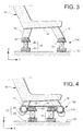
- FIG 3 is illustrated a system 100 filtering the movements of a vehicle support 19, due to vibrations from the vehicle floor 12 and transmitted to said support, which equips a support 19 of vehicle having a seat 18 and provided with four feet 14 rigidly fixed to said seat 18.
- the support 19 is shown in side view, so that only two feet 14 and two devices 10 are represented.
- Each device 10 of the system 100 is installed under the corresponding foot 14 of the support 19 of such that the axes of rotation of the devices 10 are oriented so as to be all parallel to each other, and perpendicular to the direction in which the movement propagates which must be filtered by the filter system.
- the axes of rotation of the devices 10 are oriented parallel to the vehicle advance direction.
- direction X is the forward direction of the vehicle
- direction Y is a direction cross.
- the support 19 moves according to an overall translation along a trajectory curvilinear contained in a transverse plane of the vehicle.
- Each device 10 is therefore represented by side view in FIG. 3 in a simplified manner by a base 20, and a set 80 which represents the segments mobile 24, 221, 223, and a clevis 141 for the adaptation of the device 10 to the foot 14.
- Said yoke 141 can advantageously be the screed which allows usually fix the support leg 19 to the floor, when said support 19 is a seat which is not equipped with the device or system according to the invention.
- This system configuration 100 presents the advantage of not having to change seats from already existing vehicles to equip them with the device or of the system according to the invention.
- the system 100 comprises, in addition to the devices 10, a plate common intermediate 40, rigidly fixed to the feet 14 of the support 19, by fixing means 143. It is installed at a height intermediate between the seat 18 of the support 19 and the plane of the floor 12, and is preferably arranged parallel to the plane of the floor 12.
- the devices 10 are interposed between the floor 12 and said plate intermediate 40, which constitutes the lower part integral with the seat 18 of the support 19.
- the connection between the common intermediate plate 40 and each device 10 is a rotating joint.
- This articulation in rotation is achieved by means of an axis of rotation 32 common to the longitudinal bar 221 of the "T" of the central part 22 and a yoke 141.
- the axis of rotation 32 is provided directly in the plate 40, for example in a manner analogous to axes 34 in the bases 20.
- the device and the system of the invention have just been described in an application relating to vehicle passenger supports. They are particularly suitable for filtering vibrations affecting the seats of an aircraft.
Landscapes
- Engineering & Computer Science (AREA)
- Aviation & Aerospace Engineering (AREA)
- Transportation (AREA)
- Mechanical Engineering (AREA)
- Seats For Vehicles (AREA)
- Vibration Prevention Devices (AREA)
- Filtering Of Dispersed Particles In Gases (AREA)
Abstract
Description
La présente invention se rapporte au domaine technique des supports de passager dans un véhicule, et particulièrement au filtrage des mouvements vibratoires d'un siège de véhicule.The present invention relates to technical field of passenger supports in a vehicle, and in particular the filtering of vibratory movements of a vehicle seat.
On entend généralement par support de passager un siège installé dans un véhicule, mais le terme support s'étend naturellement à d'autres éléments de mobilier pour passagers comme un lit ou une banquette.By support is generally understood passenger a seat installed in a vehicle but the term support naturally extends to other elements passenger furniture such as a bed or a bench.
L'invention trouve une application particulière pour le filtrage des mouvements vibratoires des sièges d'aéronef, lesdits mouvements vibratoires étant engendrés par les vibrations provenant du fuselage de l'aéronef et se propageant aux sièges par l'intermédiaire du plancher.The invention finds an application special for filtering movements vibration of aircraft seats, said movements being generated by vibrations from the fuselage of the aircraft and spreading to seats through the floor.
On rappelle que le filtrage des vibrations provenant du plancher consiste à confiner l'énergie vibratoire au niveau du plancher, en limitant la transmission desdites vibrations aux supports des passagers. Le filtrage des vibrations est donc différent de l'amortissement des vibrations.Remember that filtering vibrations from the floor is to confine the energy vibration at floor level, limiting the transmission of said vibrations to the supports of the passengers. Filtering vibrations is therefore different from vibration damping.
La présente invention vise un dispositif articulé, qui est interposé entre le plancher du véhicule et le support de passager, qui filtre les mouvements du support transmis par le plancher du véhicule, en permettant audit support de se déplacer le long d'une trajectoire prédéterminée et contrôlée.The present invention relates to a device articulated, which is interposed between the floor of the vehicle and passenger support, which filters out support movements transmitted by the floor of the vehicle, allowing said support to move the along a predetermined and controlled trajectory.
Elle vise également un système de filtrage des mouvements d'un support de passager, dus aux vibrations provenant du plancher du véhicule et transmises au support de passager, qui met en oeuvre de tels dispositifs articulés.It also targets a filtering system movements of a passenger support due to vibrations from the vehicle floor and transmitted to the passenger support, which implements such articulated devices.
Elle vise enfin un support de passager, équipé d'un système conforme à l'invention.Finally, it targets a passenger support, equipped with a system according to the invention.
On précise que le terme « passager » signifie ici « personne transportée », et s'étend de manière implicite au personnel de service du véhicule, le cas échéant.It is specified that the term "passenger" here means "transported person", and extends from implicitly to vehicle service personnel, if applicable.
Lors du transport de passagers dans des véhicules, les changements de trajectoire du véhicule ou les obstacles franchis par les véhicules, ou encore les moyens de propulsion engendrent des efforts qui se transmettent aux supports des passagers, et par suite aux passagers eux-mêmes.When transporting passengers in vehicles, vehicle trajectory changes or obstacles crossed by vehicles, or the means of propulsion generate efforts which pass to passenger carriers, and as a result to the passengers themselves.
On cherche le plus souvent à améliorer le confort des passagers en réduisant ces efforts ou leurs effets.We often try to improve the passenger comfort by reducing these efforts or their effects.
Par exemple, dans le cas d'un transport par
train, le franchissement rapide de courbes engendre
notamment des forces centrifuges et des forces
latérales. Le document DE 19 503 660 A1 décrit un
dispositif destiné à améliorer le confort des passagers
en réduisant les effets desdites forces centrifuges et
latérales et en amortissant les oscillations latérales
induites. Ce dispositif se trouve interposé entre le
sol, ou plancher du véhicule, et l'assise du siège, et
remplace les pieds dudit siège. Il comporte différents
composants, tels que des paliers, des tiges de
couplage, des éléments de positionnement et
d'amortissement, qui forment une ou plusieurs chaínes
cinématiques à quatre éléments disposées selon une
direction transversale du siège. Lorsque ce dispositif
est en service, le siège du passager est capable de
basculer latéralement autour d'un point de basculement
fictif (D) situé au-dessus de son centre de gravité.For example, in the case of transport by
train, the rapid crossing of curves generates
especially centrifugal forces and forces
side. The
Dans le cas d'un transport par aéronef, la situation est sensiblement différente. Un aéronef, en vol, est soumis à différentes perturbations qui excitent les surfaces portantes (voilure, dérive, ...) et/ou les installations motrices. Les vibrations engendrées par ces perturbations se propagent au plancher de la cabine de l'aéronef, par l'intermédiaire du fuselage, puis aux supports des passagers. Ces vibrations génèrent chez les passagers des troubles physiologiques , tels que malaises, nausées, inconfort, etc..., qui peuvent notablement les incommoder.In the case of transport by aircraft, the situation is significantly different. An aircraft, in flight, is subject to various disturbances which excite the bearing surfaces (wing, drift, ...) and / or power plants. Vibrations generated by these disturbances spread to the floor of the aircraft cabin, via from the fuselage, then to the passenger supports. These vibrations generate disturbances in passengers physiological, such as malaise, nausea, discomfort, etc ..., which can significantly inconvenience them.
L'utilisation du dispositif décrit dans le
DE 19 503 660 aurait pour effet que les vibrations
latérales transmises au support de passager par le
plancher seraient ressenties à l'emplacement du point
fictif (D), c'est-à-dire au niveau de la tête du
passager, ce qui n'est pas satisfaisant du point de vue
du confort. Cet inconvénient rend inadaptée
l'utilisation du dispositif décrit dans le DE 19 503
660 dans le cas du transport de passagers dans un
aéronef. The use of the device described in the
La présente invention a pour but de remédier aux inconvénients mentionnés ci-dessus du dispositif de l'art antérieur.The object of the present invention is to remedy the above mentioned drawbacks of prior art device.
Ce but est atteint au moyen d'un dispositif et d'un système aptes à filtrer les vibrations provenant du plancher de l'aéronef.This goal is achieved by a device and a system able to filter vibrations coming from the aircraft floor.
Le filtrage des vibrations transmises à un support de passager est réalisé en entraínant le support de passager de manière à ce qu'il effectue des petits déplacements le long d'une trajectoire prédéterminée et contrôlée, ladite trajectoire étant contenue dans un plan.Filtering vibrations transmitted to a passenger support is made by driving the passenger support so that it performs small displacements along a trajectory predetermined and controlled, said trajectory being contained in a plan.
Le système de filtrage conforme à l'invention est constitué d'au moins un dispositif, qui consiste en une chaíne articulée permettant ce petit déplacement du support le long d'une trajectoire plane.The filtering system according to the invention consists of at least one device, which consists of an articulated chain allowing this small displacement of the support along a flat trajectory.
Dans le cas d'un aéronef, on a constaté que les mouvements du support de passager engendrés par les vibrations du fuselage se produisent principalement dans un plan transversal, qui est perpendiculaire à l'axe du fuselage. Le dispositif et le système selon l'invention sont aptes à filtrer les mouvements vibratoires transmis au support de passager dans un plan privilégié, qui peut notamment être un plan transversal.In the case of an aircraft, it has been found that passenger support movements caused by fuselage vibrations mainly occur in a transverse plane, which is perpendicular to the axis of the fuselage. The device and the system according to the invention are able to filter movements vibration transmitted to the passenger support in a privileged plan, which can in particular be a plan transverse.
Selon l'invention, le dispositif articulé, destiné à faire partie d'un système de filtrage des mouvements vibratoires provenant d'un plancher du véhicule et transmis à un support de passager, est installé entre ledit plancher et ledit support, et comprend les cinq éléments suivants :
- deux socles solidaires du plancher du véhicule,
- une pièce centrale mobile articulée au support,
- deux tiges de liaison, articulées chacune à l'un des socles et à la pièce centrale,
- two bases secured to the vehicle floor,
- a movable central part articulated to the support,
- two connecting rods, each articulated to one of the bases and to the central part,
Ces cinq éléments étant articulés entre eux et au support par des liaisons en rotation autour de cinq axes de rotation, lesdits axes de rotation étant parallèles les uns aux autres, de telle manière que l'axe de rotation entre la pièce centrale mobile et le support se déplace en translation le long d'une trajectoire curviligne contenue dans un plan qui est perpendiculaire au plan du plancher.These five elements being articulated between them and to the support by rotating links around five axes of rotation, said axes of rotation being parallel to each other, so that the axis of rotation between the moving central part and the support moves in translation along a curvilinear trajectory contained in a plane which is perpendicular to the plane of the floor.
Un tel dispositif présente l'avantage d'être simple à mettre en oeuvre, tout en étant fiable.Such a device has the advantage to be simple to implement, while being reliable.
Le dispositif articulé peut être installé de telle manière que les cinq axes de rotation soient perpendiculaires au plan longitudinal de symétrie du véhicule. Dans ce cas, les déplacements autorisés du support de passager sont contenus dans un plan longitudinal du véhicule.The articulated device can be installed so that the five axes of rotation are perpendicular to the longitudinal plane of symmetry of the vehicle. In this case, the authorized movements of the passenger support are contained in a plane longitudinal of the vehicle.
Le dispositif articulé peut aussi être installé de telle manière que les cinq axes de rotation soient parallèles au plan antéro-postérieur du véhicule. Dans ce cas, les déplacements autorisés du support de passager sont contenus dans un plan transversal du véhicule. The articulated device can also be installed in such a way that the five axes of rotation are parallel to the anteroposterior plane of the vehicle. In this case, the authorized movements of the passenger support are contained in a plane transverse of the vehicle.
De préférence, lorsque le véhicule est un aéronef, le dispositif articulé est installé par rapport au plancher de l'aéronef avec les axes de rotation orientés selon une direction longitudinale dudit véhicule, de manière à filtrer les mouvements du support de passager selon un plan transversal.Preferably, when the vehicle is a aircraft, the articulated device is installed by relation to the aircraft floor with the axes of rotation oriented in a longitudinal direction of said vehicle, so as to filter the movements of the passenger support in a transverse plane.
De préférence, le dispositif articulé est installé entre le plancher et une partie basse du support, ladite partie basse étant solidaire de l'assise du support.Preferably, the articulated device is installed between the floor and a lower part of the support, said lower part being integral with the seat of the support.
Selon un mode de réalisation préféré de l'invention, la partie basse du support est un pied de support, par exemple un pied de siège. Dans ce cas, le système de filtrage des mouvements d'un support de passager, dus aux vibrations provenant du plancher du véhicule et transmises au support de passager, est constitué d'au moins un dispositif articulé tel que ci-dessus mentionné, chaque dispositif étant interposé entre le plancher du véhicule et l'un des pieds du support. Ainsi lorsque le support est muni d'un seul pied, le système comporte un seul dispositif. Pour des raisons de stabilité, on préfère que le support soit muni d'au moins trois pieds. Dans ce cas, le système comporte au moins trois dispositifs. De manière analogue, lorsque le support est muni de quatre pieds, le système comporte quatre dispositifs, etc ...According to a preferred embodiment of the invention, the lower part of the support is a foot support, for example a seat leg. In this case, the filtering system for the movements of a support passenger, due to vibrations from the floor of the vehicle and transmitted to the passenger support, is consisting of at least one articulated device as above mentioned, each device being interposed between the vehicle floor and one of the feet of the support. So when the support has only one foot, the system has a single device. For some stability reasons, we prefer that the support is fitted with at least three feet. In this case, the system has at least three devices. So similar, when the support is provided with four feet, the system has four devices, etc ...
Selon un autre mode de réalisation préféré de l'invention, la partie basse du support, fixée à l'assise du support, est une plaque disposée de façon à être sensiblement parallèle au plancher et fixée aux pieds du support. Dans ce cas, chaque dispositif constitutif du système de filtrage est interposé entre le plancher du véhicule et ladite plaque. Cet agencement présente l'avantage d'éviter une surélévation excessive du support lorsqu'il est équipé d'un système conforme à l'invention. En particulier, il est alors possible de raccourcir ou même de supprimer les pieds du support.According to another preferred embodiment of the invention, the lower part of the support, fixed to the seat of the support, is a plate arranged so as to be substantially parallel to the floor and fixed to support feet. In this case, each device constituting the filtering system is interposed between the vehicle floor and said plate. This the arrangement has the advantage of avoiding excessive heightening of the support when equipped of a system according to the invention. In particular, it is then possible to shorten or even delete the support legs.
Un avantage du dispositif et du système de filtrage selon l'invention réside dans le fait que l'efficacité du système de filtrage est indépendante de la masse qu'il supporte, c'est-à-dire de la masse du siège, augmentée le cas échéant de la masse d'un passager.An advantage of the device and the filtering according to the invention lies in the fact that the efficiency of the filtering system is independent of the mass it supports, i.e. the mass of the seat, increased if necessary by the mass of a passenger.
De manière optionnelle, le dispositif selon l'invention, respectivement le système selon l'invention, est équipé d'au moins un moyen ou mécanisme de blocage ou de verrouillage. Lorsque ledit moyen ou mécanisme de blocage ou de verrouillage est activé, le dispositif de filtrage, respectivement le système de filtrage, est rendu inopérant. Au contraire, lorsque ledit moyen ou mécanisme de blocage ou de verrouillage n'est pas activé, le dispositif de filtrage, respectivement le système de filtrage, filtre les mouvements vibratoires provenant du plancher du véhicule et transmis au support de passager auquel est associé ledit dispositif de filtrage, respectivement ledit système de filtrage.Optionally, the device according to the invention, respectively the system according to the invention is equipped with at least one means or blocking or locking mechanism. When said means or blocking or locking mechanism is activated, the filtering device, respectively the filtering system, is rendered inoperative. On the contrary, when said means or mechanism for blocking or lock is not activated, the locking device filtering, respectively the filtering system, filter the vibratory movements coming from the floor of the vehicle and transmitted to the passenger support which is associated said filtering device, respectively said filtering system.
L'invention sera mieux comprise à la lecture de la description détaillée qui va suivre de modes de réalisation préférés de l'invention, qui sont fournis à titre d'exemples non limitatifs, en référence aux dessins annexés dans lesquels :
- la figure 1 représente en perspective un dispositif conforme à l'invention installé sous un pied de support;
- la figure 2 est un schéma fonctionnel illustrant la cinématique du dispositif de la figure 1, dans le plan des déplacements ;
- la figure 3 illustre en vue de côté une mise en oeuvre du système de l'invention équipant un support de passager ;
- la figure 4 est analogue à la figure 3 pour une autre mise en oeuvre du système de l'invention équipant un support de passager.
- Figure 1 shows in perspective a device according to the invention installed under a support leg;
- Figure 2 is a block diagram illustrating the kinematics of the device of Figure 1, in the plane of movement;
- Figure 3 illustrates in side view an implementation of the system of the invention fitted to a passenger support;
- Figure 4 is similar to Figure 3 for another implementation of the system of the invention fitted to a passenger support.
En se référant à la figure 1, le dispositif
10 est installé entre le plancher 12 du véhicule et une
partie basse 14 solidaire d'un support (non représenté
à la figure 1) du véhicule.Referring to Figure 1, the
Le dispositif 10 comprend :
- de ux socles 20 fixés sur le plancher 12 du véhicule,
- une pièce centrale 22 en forme de « T » inversé, articulée à la partie basse 14,
- deux tiges de
liaison 24 articulées chacune d'une part à l'un des socles 20 et d'autre part à la pièce centrale 22.
- ux
bases 20 fixed on thefloor 12 of the vehicle, - a
central part 22 in the form of an inverted "T", articulated at thebottom part 14, - two connecting
rods 24 each articulated on the one hand to one of thebases 20 and on the other hand to thecentral part 22.
De manière préférée, les tiges de liaison
24 sont des biellettes doubles.Preferably, the connecting
Sur l'exemple illustré à la figure 1, la
partie basse 14 du support du véhicule est un pied 14
de support, qui est représenté en traits interrompus.
Au bas de ce pied 14 est fixée une chape 141 qui
constitue une pièce intermédiaire d'adaptation, apte à
recevoir un axe de rotation 32 pour son articulation
avec l'extrémité libre de la portion formant la barre
longitudinale 221 du « T » de la pièce centrale 22.In the example illustrated in Figure 1, the
Chaque biellette double 24 est articulée
par l'une de ses extrémités à l'un des socles fixes 20.
L'articulation est réalisée par une rotation autour
d'un axe de rotation 34, qui est également fixe.Each
Chaque biellette double 24 est également
articulée par l'autre de ses extrémités à l'une des
extrémités de la portion 223 formant la barre
transversale du « T » de la pièce centrale 22. Chacune
de ces deux articulations est réalisée par une rotation
autour d'un axe de rotation 36, qui est mobile.Each double 24 link is also
articulated by the other of its ends to one of
ends of the
Le dispositif 10 est configuré de façon que
les axes de rotation 32, 34, 36 soient parallèles entre
eux et parallèles au plan du plancher 2.The
Les biellettes doubles 24, la barre
longitudinale 221 du « T » et la barre transversale 223
du « T » présentent une épaisseur appropriée pour
supporter les axes de rotation 32, 36 par
l'intermédiaire d'un moyen autorisant un mouvement
rotatif, tel que par exemple un roulement, un palier,
ou un pivot élastique. Selon une variante, ledit moyen
autorisant un mouvement rotatif est équipé d'un moyen
amortisseur externe. Les axes de rotation 34 sont aussi
supportés dans les socles 20 par l'intermédiaire de
moyens autorisant un mouvement rotatif, qui peut être
équipé d'un moyen amortisseur externe.
Les biellettes doubles 24, la barre
longitudinale 221 du « T » et la barre transversale 223
du « T » constituent ainsi des segments d'une chaíne
cinématique dont le mouvement d'ensemble est contenu
dans un plan (Y, Z) qui est perpendiculaire à la fois
au plan (X, Y) du plancher 12 et aux axes de rotation
32, 34, 36 du dispositif 10.
La cinématique du dispositif 10 est
illustrée de façon schématique à la figure 2.The kinematics of the
Sur la figure 2, ainsi que sur les figures suivantes 3 et 4, ont été représentés les axes d'un référentiel orthonormé (X, Y, Z), défini de la manière suivante :
- le plan (X, Y) est le plan du plancher 12,
- la direction Z est perpendiculaire au plan du plancher 12,
- la direction X est la direction commune
aux axes 32, 34, 36 du
dispositif 10.
- the plane (X, Y) is the plane of the
floor 12, - the direction Z is perpendicular to the plane of the
floor 12, - direction X is the direction common to
axes device 10.
Cette figure montre, dans le plan (Y, Z)
des déplacements, les mouvements de rotation autorisés
des différents segments 221, 223, 24, autour des
différents axes de rotation 32, 34, 36. Elle montre
également la trajectoire résultante 160 d'un point A de
l'axe de rotation 32 commun à la pièce centrale 22 et
au pied 14.This figure shows, in the plane (Y, Z)
movements, rotational movements allowed
Les déplacements des segments 221, 223, 24
sont représentés entre une position de repos ou
d'équilibre, matérialisée en traits interrompus, et une
position déplacée, matérialisée en traits pleins. Displacements of
Pour faciliter la compréhension, les socles
20 ont été représentés en traits mixtes, et les
références numériques n'ont été indiquées que pour la
position déplacée (traits pleins) du dispositif 10.To facilitate understanding, the
Chacun des axes de rotation 34 d'une
extrémité de chaque biellette double 24 par rapport à
un socle 20 est fixe, puisqu'il est solidaire du socle
correspondant 20, lui-même fixe. Par conséquent l'axe
de rotation 36 de l'autre extrémité de ladite biellette
double 24 se déplace sur une trajectoire circulaire
150.Each of the axes of
La pièce centrale 22 en forme de « T » est
mobile. Son mouvement est imposé par les trajectoires
circulaires 150 des axes de rotation 36 situés à
chacune des extrémités de la barre transversale 223 du
« T ».The
Lors du déplacement de la pièce centrale
22, chaque point A de l'axe de rotation 32 de
l'extrémité de la barre longitudinale 221 du « T »
parcourt une trajectoire curviligne 160, contenue dans
un plan (Y, Z) perpendiculaire au plan (X, Z) du
plancher 12.When moving the
Il est possible de contrôler cette
trajectoire curviligne de l'axe de rotation 32 et de la
modifier, en modifiant la distance entre les deux axes
de rotation 34 fixes des socles 22 fixes, et/ou la
distance entre chacun de ces axes de rotation 34 fixes
et le plan du plancher 12, et/ou en modifiant la
longueur des segments 24, 221, 223.It is possible to control this
curvilinear trajectory of the axis of
Selon le mode de réalisation du dispositif
10 illustré aux figures 1 et 2, les axes de rotation
fixes 34 sont situés chacun à la même distance du plan
du plancher 12, et les biellettes doubles 24 présentent
la même distance entre leurs deux axes de rotation 34,
36, de telle sorte que, dans la position de repos ou
d'équilibre du dispositif 10, la barre transversale 223
du « T » de la pièce centrale 22 est parallèle au plan
du plancher 2.According to the embodiment of the
Toujours selon le mode de réalisation du
dispositif 10 illustré aux figures 1 et 2, la distance
entre les axes de rotation 34 fixes est inférieure à la
somme des longueurs des deux biellettes doubles 24 et
de la barre transversale 223 du « T » de la pièce
centrale 22. Ainsi, au cours du déplacement de la pièce
centrale 22, la barre transversale 223 du « T » reste
située entre le plan du plancher et un plan passant par
les deux axes fixes 34. Avec cette configuration
préférée, les trajectoires 150 et 160 ont leur
convexité orientée du côté du plancher 2, et la partie
basse 14 du support revient en position de repos ou
d'équilibre stable sous l'action de la pesanteur,
lorsqu'aucun autre effort ne s'exerce sur elle.Still according to the embodiment of the
L'assise du support, et par suite le
support lui-même, sont entraínés dans un mouvement
d'ensemble avec la partie basse 14.The seat of the support, and consequently the
support itself, are driven in a movement
overall with the
On va maintenant décrire le système de filtrage conforme à l'invention et deux variantes de configuration de ce système entre le plancher 2 du véhicule et l'assise du support, en référence aux figures 3 et 4.We will now describe the system of filtering according to the invention and two variants of configuration of this system between floor 2 of vehicle and seat support, with reference to Figures 3 and 4.
Le système 100 conforme à l'invention
comprend au moins un dispositif articulé 10 tel que
précédemment décrit, qui est installé entre le plancher
12 du véhicule et une partie basse 14, 40, 18 du
support 19. Ladite partie basse peut avantageusement
être un pied 14 du support ou une plaque intermédiaire
commune 40 (qui sera décrite ultérieurement), ou même
l'assise 18 du support 19.
Lorsque le système 100 ne comprend qu'un
seul dispositif 10, il est nécessaire de compléter ce
système par des moyens de butée additionnels pour
limiter les déplacements de ladite partie basse du
support.When the
C'est pourquoi, il est préféré,
conformément à l'invention, que le système comprenne au
moins trois dispositifs 10 tels que précédemment
décrits. Une telle configuration est conforme avec les
exigences usuelles de stabilité du support, qui est
muni à cet effet d'au moins trois pieds, et le plus
souvent de quatre pieds.Therefore, it is preferred,
according to the invention, that the system comprises at
minus three
Sur la figure 3 est illustré un système 100
de filtrage des mouvements d'un support 19 de véhicule,
dus aux vibrations provenant du plancher 12 du véhicule
et transmises audit support, qui équipe un support 19
de véhicule ayant une assise 18 et muni de quatre pieds
14 rigidement fixés à ladite assise 18. Le support 19
est représenté en vue latérale, de telle sorte que
seulement deux pieds 14 et deux dispositifs 10 sont
représentés.In Figure 3 is illustrated a
Chaque dispositif 10 du système 100 est
installé sous le pied 14 correspondant du support 19 de
telle manière que les axes de rotation des dispositifs
10 se trouvent orientés de manière à être tous
parallèles entre eux, et perpendiculaires à la
direction suivant laquelle se propage le mouvement qui
doit être filtré par le système de filtrage.Each
Dans le cas où le véhicule est un aéronef,
il est donc préféré que les axes de rotation des
dispositifs 10 soient orientés parallèlement à la
direction d'avancée du véhicule. Selon la convention
d'axes habituellement en vigueur dans le domaine des
aéronefs, la direction X est la direction d'avancée du
véhicule, et la direction Y est une direction
transversale. Par suite, le support 19 se déplace selon
une translation d'ensemble le long d'une trajectoire
curviligne contenue dans un plan transversal du
véhicule.If the vehicle is an aircraft,
it is therefore preferred that the axes of rotation of the
Chaque dispositif 10 est donc représenté en
vue latérale à la figure 3 de façon simplifiée par un
socle 20, et un ensemble 80 qui figure les segments
mobiles 24, 221, 223, et une chape 141 pour
l'adaptation du dispositif 10 au pied 14. Ladite chape
141 peut avantageusement être la chape qui permet de
fixer usuellement le pied du support 19 au plancher,
lorsque ledit support 19 est un siège qui n'est pas
équipé du dispositif ou du système selon l'invention.Each
Cette configuration du système 100 présente
l'avantage de ne pas avoir à modifier des sièges de
véhicules déjà existants pour les équiper du dispositif
ou du système selon l'invention.This
Mais cette configuration du système 100
présente parfois l'inconvénient de surélever le support
19. But this
Pour pallier cet inconvénient, une variante de configuration du système est proposée. Elle est illustrée à la figure 4, qui ne sera décrite que pour ses différences avec la figure 3.To overcome this drawback, a variant system configuration is proposed. She is illustrated in Figure 4, which will only be described for its differences from Figure 3.
Selon cette variante, le système 100
comprend, outre les dispositifs 10, une plaque
intermédiaire commune 40, fixée rigidement aux pieds 14
du support 19, par des moyens de fixation 143. Elle est
installée à une hauteur intermédiaire entre l'assise 18
du support 19 et le plan du plancher 12, et se trouve
de préférence disposée parallèlement au plan du
plancher 12.According to this variant, the
Selon cette variante, les dispositifs 10
sont interposés entre le plancher 12 et ladite plaque
intermédiaire 40, qui constitue la partie basse
solidaire de l'assise 18 du support 19. La liaison
entre la plaque intermédiaire commune 40 et chaque
dispositif 10 est une articulation en rotation. Cette
articulation en rotation est réalisée au moyen d'un axe
de rotation 32 commun à la barre longitudinale 221 du
« T » de la partie centrale 22 et à une chape 141.
Selon une variante non représentée à la figure 4, l'axe
de rotation 32 est ménagé directement dans la plaque
40, par exemple d'une manière analogue aux axes 34 dans
les socles 20.According to this variant, the
D'autres variantes possibles de configuration du système n'ont pas été représentées aux figures.Other possible variants of system configuration have not been shown to FIGS.
On peut envisager une variante dans
laquelle la plaque intermédiaire commune 40 n'est pas
fixée aux pieds 14 du support, mais directement à
l'assise 18 du support 19. Dans ce cas, il est même
possible de raccourcir ou de supprimer les pieds du
support, tout en prévoyant des moyens pour que l'assise
18 du support 19 se trouve à une hauteur normalisée du
plancher 12.We can consider a variant in
which the common
On peut également envisager une autre
variante, dans laquelle la partie basse du support est
l'assise 18 du support elle-même. Dans ce cas, la
présence d'une plaque intermédiaire 40 n'est plus
nécessaire. La présence de pieds 14 n'est plus
nécessaire non plus. Là aussi, des moyens doivent être
prévus pour assurer une hauteur suffisante entre
l'assise 18 du support 19 et le plancher 12.We can also consider another
variant, in which the lower part of the support is
the
Le dispositif et le système de l'invention viennent d'être décrits dans une application relative à des supports de passagers d'un véhicule. Ils sont particulièrement adaptés au filtrage des vibrations affectant les sièges d'un aéronef.The device and the system of the invention have just been described in an application relating to vehicle passenger supports. They are particularly suitable for filtering vibrations affecting the seats of an aircraft.
Ils peuvent être étendus à d'autres applications relatives à d'autres éléments de mobilier pour passager, comme un lit ou une banquette, ou une plate-forme, ou à tout support destiné à recevoir un ou des passager(s) et dont on souhaite améliorer le confort dans des conditions de vibrations subies par ce (s) passager(s), sans pour autant sortir du cadre de l'invention.They can be extended to others applications relating to other pieces of furniture for passenger, such as a bed or bench, or a platform, or any support intended to receive one or of passenger (s) and whose comfort in conditions of vibrations undergone by this passenger (s), without departing from the scope of the invention.
Claims (19)
Applications Claiming Priority (2)
| Application Number | Priority Date | Filing Date | Title |
|---|---|---|---|
| FR0211610A FR2844752B1 (en) | 2002-09-19 | 2002-09-19 | DEVICE AND SYSTEM FOR FILTERING THE VIBRATORY MOVEMENTS OF A PASSENGER SUPPORT, AND PASSENGER SUPPORT PROVIDED WITH SUCH A SYSTEM |
| FR0211610 | 2002-09-19 |
Publications (2)
| Publication Number | Publication Date |
|---|---|
| EP1400398A1 true EP1400398A1 (en) | 2004-03-24 |
| EP1400398B1 EP1400398B1 (en) | 2006-04-19 |
Family
ID=31897500
Family Applications (1)
| Application Number | Title | Priority Date | Filing Date |
|---|---|---|---|
| EP03103429A Expired - Lifetime EP1400398B1 (en) | 2002-09-19 | 2003-09-17 | Device and system for filtering vibratory mouvements of a passenger support, and passenger support equiped with such a system. |
Country Status (7)
| Country | Link |
|---|---|
| US (1) | US6857674B2 (en) |
| EP (1) | EP1400398B1 (en) |
| AT (1) | ATE323622T1 (en) |
| CA (1) | CA2440972C (en) |
| DE (1) | DE60304643T2 (en) |
| ES (1) | ES2261878T3 (en) |
| FR (1) | FR2844752B1 (en) |
Cited By (1)
| Publication number | Priority date | Publication date | Assignee | Title |
|---|---|---|---|---|
| US10065541B2 (en) | 2015-08-10 | 2018-09-04 | Grammer Ag | Horizontal vibration device for a vehicle seat |
Families Citing this family (22)
| Publication number | Priority date | Publication date | Assignee | Title |
|---|---|---|---|---|
| KR101449016B1 (en) * | 2007-12-27 | 2014-10-13 | 두산인프라코어 주식회사 | Cabin mounting structure for construction machinery |
| DE102010033028B4 (en) | 2010-08-02 | 2014-02-27 | Grammer Aktiengesellschaft | Vehicle vibration device with a horizontal suspension device |
| DE102010033419A1 (en) | 2010-08-04 | 2012-02-09 | Grammer Aktiengesellschaft | Horizon spring device for vehicle seats with elastomer spring element with progressive spring characteristic |
| DE102010034857B4 (en) * | 2010-08-18 | 2021-01-28 | Grammer Aktiengesellschaft | Vehicle vibration device for vehicle seats |
| DE102010051326A1 (en) | 2010-08-31 | 2012-03-01 | Grammer Aktiengesellschaft | Vehicle seat for vehicles |
| DE102010052619A1 (en) | 2010-11-29 | 2012-05-31 | Grammer Aktiengesellschaft | Vehicle seat with guided scissor arms |
| DE102010053752A1 (en) * | 2010-12-08 | 2012-06-14 | Grammer Aktiengesellschaft | Vehicle vibration device for vehicle seats or vehicle cabins |
| DE102010054749B4 (en) | 2010-12-15 | 2013-10-24 | Grammer Aktiengesellschaft | Suspension device for vehicle seats and / or vehicle cabins with elastomeric element |
| DE102011053647B4 (en) | 2011-09-15 | 2022-02-03 | Grammer Aktiengesellschaft | Vehicle seat with a suspension device and motor vehicle |
| DE102012102574A1 (en) * | 2012-03-26 | 2013-09-26 | Dornier Technologie Gmbh & Co. Kg | storage device |
| US10046677B2 (en) | 2013-04-23 | 2018-08-14 | Clearmotion Acquisition I Llc | Seat system for a vehicle |
| DE102013104926A1 (en) * | 2013-05-14 | 2014-11-20 | Grammer Ag | Vehicle vibration device, vehicle seat and vehicle cabin |
| DE102013110370B4 (en) | 2013-06-04 | 2014-12-11 | Grammer Ag | vehicle seat |
| DE102013106709A1 (en) | 2013-06-26 | 2014-12-31 | Grammer Ag | Device with a suspension system |
| DE102013110924B4 (en) | 2013-10-01 | 2018-02-08 | Grammer Ag | Vehicle with force-controlled damper with control valve |
| DE102013110920B4 (en) | 2013-10-01 | 2018-08-16 | Grammer Ag | Vehicle seat with force-controlled damper (2-pipe damper) |
| DE102013110923B4 (en) | 2013-10-01 | 2019-07-04 | Grammer Ag | Vehicle seat or vehicle cabin with a suspension device and utility vehicle |
| DE102013110919B4 (en) | 2013-10-01 | 2018-08-02 | Grammer Ag | shock absorber |
| DE102013021561B4 (en) | 2013-12-16 | 2020-09-03 | Grammer Ag | Vehicle seat with a horizontally movable seat surface to accommodate a person |
| DE102018001802A1 (en) * | 2018-03-07 | 2019-09-12 | Eveline Kladov | Aircraft seat stabilizers |
| DE102018217697A1 (en) * | 2018-10-16 | 2020-04-16 | Volkswagen Aktiengesellschaft | Vehicle seat for a motor vehicle |
| CN112306098A (en) * | 2019-07-26 | 2021-02-02 | 王楚涵 | Level gauge, supporting tool and method for adjusting level of bearing surface of supporting tool surface |
Citations (5)
| Publication number | Priority date | Publication date | Assignee | Title |
|---|---|---|---|---|
| FR1335575A (en) * | 1962-07-09 | 1963-08-23 | Assembly incorporating an anti-vibration device | |
| US3632076A (en) * | 1970-02-09 | 1972-01-04 | Thomas J Rogers Jr | Self-leveling seat structure |
| US4003534A (en) * | 1975-11-05 | 1977-01-18 | United Technologies Corporation | Pilot seat with lateral vibration isolation |
| US4183492A (en) * | 1977-10-11 | 1980-01-15 | Willibald Grammer | Vehicle seat |
| DE19503660A1 (en) * | 1995-01-24 | 1996-07-25 | Deutsche Waggonbau Ag | Seat linkage for passenger seat, especially for rail vehicle |
Family Cites Families (13)
| Publication number | Priority date | Publication date | Assignee | Title |
|---|---|---|---|---|
| US3006594A (en) * | 1958-11-12 | 1961-10-31 | Gen Motors Corp | Linkage seat adjuster with straight line movement |
| US3136524A (en) * | 1962-06-18 | 1964-06-09 | Ferro Stamping Co | Vehicle seat track |
| US4344597A (en) * | 1980-04-21 | 1982-08-17 | Milsco Manufacturing Company | Vehicle seat with fore-and-aft shock isolation |
| US5127699A (en) * | 1988-04-18 | 1992-07-07 | Kubota Tekko Kabushiki Kaisha | Device for reversibly supporting seat for vehicles |
| DE4119418C1 (en) * | 1991-06-13 | 1993-01-14 | Mercedes-Benz Aktiengesellschaft, 7000 Stuttgart, De | |
| US5374022A (en) * | 1993-04-19 | 1994-12-20 | Gilmer, Jr.; Carl D. | Tilting mechanism for marine boat seating |
| US5765803A (en) * | 1995-12-15 | 1998-06-16 | Graham; David S. | Vehicle seat suspension system |
| CA2289839C (en) * | 1997-05-27 | 2003-02-11 | Bertrand Faure Components Ltd. | Slide/fold/ez entry seat mechanism |
| US6371456B1 (en) * | 1999-02-04 | 2002-04-16 | Freightliner Llc | Seat suspension system |
| US6340152B1 (en) * | 1999-02-04 | 2002-01-22 | Freightliner Llc | Seat suspension vibration damper |
| DE19915138C2 (en) * | 1999-03-26 | 2003-12-11 | Isringhausen Geb | Air-suspended vehicle seat with constant static height |
| EP1291232B1 (en) * | 2001-09-10 | 2006-11-15 | C.Rob. Hammerstein GmbH & Co.KG | Automotive vehicle seat frame with a seat support and front parallelogram arms |
| JP4040910B2 (en) * | 2002-05-31 | 2008-01-30 | 富士機工株式会社 | Seat lifter stopper structure |
-
2002
- 2002-09-19 FR FR0211610A patent/FR2844752B1/en not_active Expired - Fee Related
-
2003
- 2003-09-03 US US10/655,512 patent/US6857674B2/en not_active Expired - Fee Related
- 2003-09-15 CA CA2440972A patent/CA2440972C/en not_active Expired - Fee Related
- 2003-09-17 EP EP03103429A patent/EP1400398B1/en not_active Expired - Lifetime
- 2003-09-17 AT AT03103429T patent/ATE323622T1/en not_active IP Right Cessation
- 2003-09-17 ES ES03103429T patent/ES2261878T3/en not_active Expired - Lifetime
- 2003-09-17 DE DE60304643T patent/DE60304643T2/en not_active Expired - Lifetime
Patent Citations (5)
| Publication number | Priority date | Publication date | Assignee | Title |
|---|---|---|---|---|
| FR1335575A (en) * | 1962-07-09 | 1963-08-23 | Assembly incorporating an anti-vibration device | |
| US3632076A (en) * | 1970-02-09 | 1972-01-04 | Thomas J Rogers Jr | Self-leveling seat structure |
| US4003534A (en) * | 1975-11-05 | 1977-01-18 | United Technologies Corporation | Pilot seat with lateral vibration isolation |
| US4183492A (en) * | 1977-10-11 | 1980-01-15 | Willibald Grammer | Vehicle seat |
| DE19503660A1 (en) * | 1995-01-24 | 1996-07-25 | Deutsche Waggonbau Ag | Seat linkage for passenger seat, especially for rail vehicle |
Cited By (1)
| Publication number | Priority date | Publication date | Assignee | Title |
|---|---|---|---|---|
| US10065541B2 (en) | 2015-08-10 | 2018-09-04 | Grammer Ag | Horizontal vibration device for a vehicle seat |
Also Published As
| Publication number | Publication date |
|---|---|
| FR2844752B1 (en) | 2004-11-05 |
| US6857674B2 (en) | 2005-02-22 |
| EP1400398B1 (en) | 2006-04-19 |
| DE60304643T2 (en) | 2007-04-05 |
| DE60304643D1 (en) | 2006-05-24 |
| US20040056501A1 (en) | 2004-03-25 |
| FR2844752A1 (en) | 2004-03-26 |
| CA2440972C (en) | 2012-03-06 |
| CA2440972A1 (en) | 2004-03-19 |
| ES2261878T3 (en) | 2006-11-16 |
| ATE323622T1 (en) | 2006-05-15 |
Similar Documents
| Publication | Publication Date | Title |
|---|---|---|
| EP1400398B1 (en) | Device and system for filtering vibratory mouvements of a passenger support, and passenger support equiped with such a system. | |
| EP2712804B1 (en) | Landing gear provided with a stiffening element to increase its roll stiffness, and aircraft | |
| EP2671556B1 (en) | Powered wheelchair | |
| EP2878537B1 (en) | Bucket seat with scalable kinematics | |
| EP2878535B1 (en) | Skid landing gear provided with at least one crossmember with beams and aircraft | |
| FR2794079A1 (en) | BABY CARRIER ASSEMBLY FOR A VEHICLE SEAT AND METHOD FOR CONTROLLING THE POSITION | |
| FR2880862A1 (en) | REAR TRAIN FOR BICYCLE | |
| FR2676416A1 (en) | RAILWAY BOGIE WITH CHASSIS WITH SELECTIVE DEFORMABILITY. | |
| EP2455269A1 (en) | Rail vehicle bogie including an eddy-current braking device | |
| FR2644743A1 (en) | BOGIE WITH DEFORMABLE CHASSIS | |
| FR2571003A1 (en) | LOCKING DEVICE FOR A SEAT SUSPENSION, PARTICULARLY FOR VEHICLES | |
| EP4175728B1 (en) | Passenger restraint system for roller coasters | |
| FR2822780A1 (en) | BOGIE FOR RAILWAY VEHICLES WITH VARIABLE GAP | |
| EP1712442B1 (en) | Device for suspending a motor from a bogie frame | |
| EP3222486A1 (en) | Railway vehicle bogie comprising a lowered body | |
| EP3042821B1 (en) | Bogie with centralized primary suspension | |
| FR2575429A1 (en) | Improvements to bogies of rail vehicles | |
| FR2531918A1 (en) | Shock absorber for vehicle loads | |
| EP3418124A1 (en) | Folding seat with storage device for headrest | |
| EP0767079B1 (en) | Beam for a trailer | |
| CA2325868C (en) | Assembly comprising a first chassis and a second chassis hanging laterally with respect to the first chassis, and associated rail vehicle | |
| FR3062113A1 (en) | RAIL VEHICLE BOGIE COMPRISING A BRAKE SYSTEM COMPRISING THREE BRAKE DISCS AGENCIES BETWEEN THE AXLE BOXES. | |
| FR3051759A1 (en) | TRANSPORT VEHICLE TO BE TRACTED BY AN AIR CABLE AND INSTALLATION COMPRISING SUCH A VEHICLE | |
| EP2905194B1 (en) | Connection arrangement between a vehicle body and a bogie frame | |
| WO2015124842A1 (en) | Sled |
Legal Events
| Date | Code | Title | Description |
|---|---|---|---|
| PUAI | Public reference made under article 153(3) epc to a published international application that has entered the european phase |
Free format text: ORIGINAL CODE: 0009012 |
|
| AK | Designated contracting states |
Kind code of ref document: A1 Designated state(s): AT BE BG CH CY CZ DE DK EE ES FI FR GB GR HU IE IT LI LU MC NL PT RO SE SI SK TR |
|
| AX | Request for extension of the european patent |
Extension state: AL LT LV MK |
|
| 17P | Request for examination filed |
Effective date: 20040630 |
|
| AKX | Designation fees paid |
Designated state(s): AT BE BG CH CY CZ DE DK EE ES FI FR GB GR HU IE IT LI LU MC NL PT RO SE SI SK TR |
|
| GRAP | Despatch of communication of intention to grant a patent |
Free format text: ORIGINAL CODE: EPIDOSNIGR1 |
|
| GRAS | Grant fee paid |
Free format text: ORIGINAL CODE: EPIDOSNIGR3 |
|
| GRAA | (expected) grant |
Free format text: ORIGINAL CODE: 0009210 |
|
| AK | Designated contracting states |
Kind code of ref document: B1 Designated state(s): AT BE BG CH CY CZ DE DK EE ES FI FR GB GR HU IE IT LI LU MC NL PT RO SE SI SK TR |
|
| PG25 | Lapsed in a contracting state [announced via postgrant information from national office to epo] |
Ref country code: CZ Free format text: LAPSE BECAUSE OF FAILURE TO SUBMIT A TRANSLATION OF THE DESCRIPTION OR TO PAY THE FEE WITHIN THE PRESCRIBED TIME-LIMIT Effective date: 20060419 Ref country code: AT Free format text: LAPSE BECAUSE OF FAILURE TO SUBMIT A TRANSLATION OF THE DESCRIPTION OR TO PAY THE FEE WITHIN THE PRESCRIBED TIME-LIMIT Effective date: 20060419 Ref country code: NL Free format text: LAPSE BECAUSE OF FAILURE TO SUBMIT A TRANSLATION OF THE DESCRIPTION OR TO PAY THE FEE WITHIN THE PRESCRIBED TIME-LIMIT Effective date: 20060419 Ref country code: SK Free format text: LAPSE BECAUSE OF FAILURE TO SUBMIT A TRANSLATION OF THE DESCRIPTION OR TO PAY THE FEE WITHIN THE PRESCRIBED TIME-LIMIT Effective date: 20060419 Ref country code: RO Free format text: LAPSE BECAUSE OF FAILURE TO SUBMIT A TRANSLATION OF THE DESCRIPTION OR TO PAY THE FEE WITHIN THE PRESCRIBED TIME-LIMIT Effective date: 20060419 Ref country code: SI Free format text: LAPSE BECAUSE OF FAILURE TO SUBMIT A TRANSLATION OF THE DESCRIPTION OR TO PAY THE FEE WITHIN THE PRESCRIBED TIME-LIMIT Effective date: 20060419 Ref country code: FI Free format text: LAPSE BECAUSE OF FAILURE TO SUBMIT A TRANSLATION OF THE DESCRIPTION OR TO PAY THE FEE WITHIN THE PRESCRIBED TIME-LIMIT Effective date: 20060419 Ref country code: IE Free format text: LAPSE BECAUSE OF FAILURE TO SUBMIT A TRANSLATION OF THE DESCRIPTION OR TO PAY THE FEE WITHIN THE PRESCRIBED TIME-LIMIT Effective date: 20060419 |
|
| REG | Reference to a national code |
Ref country code: GB Ref legal event code: FG4D Free format text: NOT ENGLISH |
|
| REF | Corresponds to: |
Ref document number: 60304643 Country of ref document: DE Date of ref document: 20060524 Kind code of ref document: P |
|
| REG | Reference to a national code |
Ref country code: IE Ref legal event code: FG4D Free format text: LANGUAGE OF EP DOCUMENT: FRENCH |
|
| PG25 | Lapsed in a contracting state [announced via postgrant information from national office to epo] |
Ref country code: DK Free format text: LAPSE BECAUSE OF FAILURE TO SUBMIT A TRANSLATION OF THE DESCRIPTION OR TO PAY THE FEE WITHIN THE PRESCRIBED TIME-LIMIT Effective date: 20060719 |
|
| REG | Reference to a national code |
Ref country code: SE Ref legal event code: TRGR |
|
| GBT | Gb: translation of ep patent filed (gb section 77(6)(a)/1977) |
Effective date: 20060719 |
|
| PG25 | Lapsed in a contracting state [announced via postgrant information from national office to epo] |
Ref country code: PT Free format text: LAPSE BECAUSE OF FAILURE TO SUBMIT A TRANSLATION OF THE DESCRIPTION OR TO PAY THE FEE WITHIN THE PRESCRIBED TIME-LIMIT Effective date: 20060919 |
|
| PG25 | Lapsed in a contracting state [announced via postgrant information from national office to epo] |
Ref country code: MC Free format text: LAPSE BECAUSE OF NON-PAYMENT OF DUE FEES Effective date: 20060930 Ref country code: BE Free format text: LAPSE BECAUSE OF NON-PAYMENT OF DUE FEES Effective date: 20060930 |
|
| NLV1 | Nl: lapsed or annulled due to failure to fulfill the requirements of art. 29p and 29m of the patents act | ||
| REG | Reference to a national code |
Ref country code: IE Ref legal event code: FD4D |
|
| REG | Reference to a national code |
Ref country code: ES Ref legal event code: FG2A Ref document number: 2261878 Country of ref document: ES Kind code of ref document: T3 |
|
| PLBE | No opposition filed within time limit |
Free format text: ORIGINAL CODE: 0009261 |
|
| STAA | Information on the status of an ep patent application or granted ep patent |
Free format text: STATUS: NO OPPOSITION FILED WITHIN TIME LIMIT |
|
| 26N | No opposition filed |
Effective date: 20070122 |
|
| BERE | Be: lapsed |
Owner name: AIRBUS FRANCE Effective date: 20060930 |
|
| PG25 | Lapsed in a contracting state [announced via postgrant information from national office to epo] |
Ref country code: GR Free format text: LAPSE BECAUSE OF FAILURE TO SUBMIT A TRANSLATION OF THE DESCRIPTION OR TO PAY THE FEE WITHIN THE PRESCRIBED TIME-LIMIT Effective date: 20060720 |
|
| REG | Reference to a national code |
Ref country code: CH Ref legal event code: PL |
|
| PG25 | Lapsed in a contracting state [announced via postgrant information from national office to epo] |
Ref country code: EE Free format text: LAPSE BECAUSE OF FAILURE TO SUBMIT A TRANSLATION OF THE DESCRIPTION OR TO PAY THE FEE WITHIN THE PRESCRIBED TIME-LIMIT Effective date: 20060419 Ref country code: BG Free format text: LAPSE BECAUSE OF FAILURE TO SUBMIT A TRANSLATION OF THE DESCRIPTION OR TO PAY THE FEE WITHIN THE PRESCRIBED TIME-LIMIT Effective date: 20060719 |
|
| PG25 | Lapsed in a contracting state [announced via postgrant information from national office to epo] |
Ref country code: LI Free format text: LAPSE BECAUSE OF NON-PAYMENT OF DUE FEES Effective date: 20070930 Ref country code: TR Free format text: LAPSE BECAUSE OF FAILURE TO SUBMIT A TRANSLATION OF THE DESCRIPTION OR TO PAY THE FEE WITHIN THE PRESCRIBED TIME-LIMIT Effective date: 20060419 Ref country code: LU Free format text: LAPSE BECAUSE OF NON-PAYMENT OF DUE FEES Effective date: 20060917 Ref country code: CH Free format text: LAPSE BECAUSE OF NON-PAYMENT OF DUE FEES Effective date: 20070930 Ref country code: HU Free format text: LAPSE BECAUSE OF FAILURE TO SUBMIT A TRANSLATION OF THE DESCRIPTION OR TO PAY THE FEE WITHIN THE PRESCRIBED TIME-LIMIT Effective date: 20061020 |
|
| PG25 | Lapsed in a contracting state [announced via postgrant information from national office to epo] |
Ref country code: CY Free format text: LAPSE BECAUSE OF FAILURE TO SUBMIT A TRANSLATION OF THE DESCRIPTION OR TO PAY THE FEE WITHIN THE PRESCRIBED TIME-LIMIT Effective date: 20060419 |
|
| REG | Reference to a national code |
Ref country code: GB Ref legal event code: 732E Free format text: REGISTERED BETWEEN 20110721 AND 20110727 |
|
| REG | Reference to a national code |
Ref country code: FR Ref legal event code: CA Effective date: 20110916 Ref country code: FR Ref legal event code: CD Owner name: AIRBUS HOLDING, FR Effective date: 20110916 Ref country code: FR Ref legal event code: CJ Effective date: 20110916 Ref country code: FR Ref legal event code: TP Owner name: AIRBUS HOLDING, FR Effective date: 20110913 |
|
| REG | Reference to a national code |
Ref country code: ES Ref legal event code: PC2A Owner name: AIRBUS OPERATIONS SAS Effective date: 20120308 |
|
| REG | Reference to a national code |
Ref country code: DE Ref legal event code: R082 Ref document number: 60304643 Country of ref document: DE Representative=s name: HENKEL, BREUER & PARTNER, DE |
|
| REG | Reference to a national code |
Ref country code: DE Ref legal event code: R081 Ref document number: 60304643 Country of ref document: DE Owner name: AIRBUS OPERATIONS SAS, FR Free format text: FORMER OWNER: AIRBUS FRANCE, TOULOUSE, FR Effective date: 20120326 Ref country code: DE Ref legal event code: R082 Ref document number: 60304643 Country of ref document: DE Representative=s name: PATENTANWAELTE HENKEL, BREUER & PARTNER, DE Effective date: 20120326 |
|
| PGFP | Annual fee paid to national office [announced via postgrant information from national office to epo] |
Ref country code: SE Payment date: 20120919 Year of fee payment: 10 |
|
| PGFP | Annual fee paid to national office [announced via postgrant information from national office to epo] |
Ref country code: IT Payment date: 20120924 Year of fee payment: 10 Ref country code: ES Payment date: 20120926 Year of fee payment: 10 |
|
| PGFP | Annual fee paid to national office [announced via postgrant information from national office to epo] |
Ref country code: DE Payment date: 20130919 Year of fee payment: 11 |
|
| PGFP | Annual fee paid to national office [announced via postgrant information from national office to epo] |
Ref country code: GB Payment date: 20130919 Year of fee payment: 11 |
|
| REG | Reference to a national code |
Ref country code: SE Ref legal event code: EUG |
|
| PG25 | Lapsed in a contracting state [announced via postgrant information from national office to epo] |
Ref country code: SE Free format text: LAPSE BECAUSE OF NON-PAYMENT OF DUE FEES Effective date: 20130918 |
|
| PG25 | Lapsed in a contracting state [announced via postgrant information from national office to epo] |
Ref country code: IT Free format text: LAPSE BECAUSE OF NON-PAYMENT OF DUE FEES Effective date: 20130917 |
|
| REG | Reference to a national code |
Ref country code: DE Ref legal event code: R119 Ref document number: 60304643 Country of ref document: DE |
|
| GBPC | Gb: european patent ceased through non-payment of renewal fee |
Effective date: 20140917 |
|
| REG | Reference to a national code |
Ref country code: ES Ref legal event code: FD2A Effective date: 20150709 |
|
| PG25 | Lapsed in a contracting state [announced via postgrant information from national office to epo] |
Ref country code: GB Free format text: LAPSE BECAUSE OF NON-PAYMENT OF DUE FEES Effective date: 20140917 Ref country code: DE Free format text: LAPSE BECAUSE OF NON-PAYMENT OF DUE FEES Effective date: 20150401 Ref country code: ES Free format text: LAPSE BECAUSE OF NON-PAYMENT OF DUE FEES Effective date: 20130918 |
|
| REG | Reference to a national code |
Ref country code: FR Ref legal event code: PLFP Year of fee payment: 14 |
|
| PGFP | Annual fee paid to national office [announced via postgrant information from national office to epo] |
Ref country code: FR Payment date: 20160921 Year of fee payment: 14 |
|
| REG | Reference to a national code |
Ref country code: FR Ref legal event code: ST Effective date: 20180531 |
|
| PG25 | Lapsed in a contracting state [announced via postgrant information from national office to epo] |
Ref country code: FR Free format text: LAPSE BECAUSE OF NON-PAYMENT OF DUE FEES Effective date: 20171002 |